JP3597708B2 - Depressurizing device and depressurizing method for hydraulic working machine - Google Patents
Depressurizing device and depressurizing method for hydraulic working machine Download PDFInfo
- Publication number
- JP3597708B2 JP3597708B2 JP22908798A JP22908798A JP3597708B2 JP 3597708 B2 JP3597708 B2 JP 3597708B2 JP 22908798 A JP22908798 A JP 22908798A JP 22908798 A JP22908798 A JP 22908798A JP 3597708 B2 JP3597708 B2 JP 3597708B2
- Authority
- JP
- Japan
- Prior art keywords
- hydraulic
- pressure
- valve
- control valve
- tank
- Prior art date
- Legal status (The legal status is an assumption and is not a legal conclusion. Google has not performed a legal analysis and makes no representation as to the accuracy of the status listed.)
- Expired - Lifetime
Links
Images


Description
【0001】
【発明の属する技術分野】
本発明は油圧ショベル等の油圧作業機械において、アタッチメントの交換やメンテナンス時に配管内に閉じこもった圧力を開放することができる油圧作業機械の圧抜き装置及び圧抜き方法に関するものである。
【0002】
【従来の技術】
従来、油圧によるパイロット圧で操作されるコントロールバルブを備えた油圧ショベルにおいては、例えばアタッチメントであるバケットをオプションとしての圧砕機に交換する場合があり、この際、アタッチメントが油圧管路から取り外される。このとき、油圧管路内には圧力が閉じ込められているため、アタッチメントを取り外すと圧力が一気に外部に開放され、作動油が噴出してしまう。
【0003】
そこで、油圧管路内に閉じこもった圧力を抜くために、油圧ポンプから吐出される作動油をタンクに戻し圧力を開放する必要がある。具体的には、コントロールバルブのスプールを動かして圧抜き制御可能な油圧管路に切り換えるという作業が行われる。
【0004】
【発明が解決しようとする課題】
しかしながら、コントロールバルブのスプールがパイロット圧で操作されるいわゆる油圧式コントロールバルブでは、そのパイロット圧の圧力源であるパイロットポンプを駆動させるためにエンジンを始動させなければならない。そこでエンジンを始動させると、パイロットポンプと連動してメインポンプが駆動するため、アタッチメントにつながっている油圧配管に作動油が流れてしまうことになる。従って、コントロールバルブのみを操作したい場合、すなわち、スプールのみタンク連通位置に切り換えて圧力開放を行いたい場合であっても、メインポンプから吐出される作動油によって回路圧が立ってしまい、圧力を開放させることができないという不都合がある。
【0005】
そこで、コントロールバルブを操作するパイロット圧ラインに補助油圧源としてアキュムレータを付加し、エンジン停止後であってもそのアキュムレータに蓄積された油圧を用いてコントロールバルブのスプールをタンク連通位置に切り換えるように構成することもできるが、この場合、回路の構成が複雑になり、アキュムレータを付加することによるコストアップが避けられない。
【0006】
本発明は以上のような従来の油圧回路における課題を考慮してなされたものであり、補助油圧源を備えることなく、コントロールバルブを操作可能にして管内に閉じこめられた圧力を開放することができる油圧作業機械の圧抜き装置及び圧抜き方法を提供するものである。
【0007】
【課題を解決するための手段】
本発明は、エンジンの始動によってメインポンプとパイロットポンプが駆動し、メインポンプから吐出される作動油は油圧式方向制御弁を介してアクチュエータに供給され、パイロットポンプから吐出されるパイロット圧は油圧式方向制御弁の操作に供せられる油圧作業機械において、圧抜きを指示する操作体と、その操作体によって圧抜きが指示された際に、油圧式方向制御弁へ導入するパイロット圧は確保しつつ、メインポンプから吐出される作動油の供給路を油圧式方向制御弁の手前側でタンクと連通させて作動油を低圧にする圧抜き手段と、を備えてなる油圧作業機械の圧抜き装置である。
【0008】
本発明は、上記構成を有する圧抜き装置において、複数のメインポンプと油圧式方向制御弁との間に合流位置と非合流位置を持つ切換弁を備え、その切換弁に、メインポンプからの作動油供給路をタンクに連通させるタンク連通路を付加し、操作体によって圧抜きが指示された際に、切換弁をタンク連通位置に切り換える切換手段を有する油圧作業機械の圧抜き装置である。
【0009】
本発明は、上記構成を有する圧抜き装置において、複数のセンターバイパスライン上に設けられる油圧式方向制御弁及び開弁状態でメインポンプからの作動油をタンクに逃がすカット弁と、作動油を一方のセンターバイパスラインのみへ導く第一の位置と双方のセンターバイパスラインへ導く第二の位置を持つ走行直進弁と、操作体によって圧抜きが指示された際に、走行直進弁を第二の位置にして他方のセンターバイパスライン上のカット弁を開く切換制御手段と、を備えてなる油圧作業機械の圧抜き装置である。
【0010】
本発明の圧抜き方法は、エンジンの始動によってメインポンプとパイロットポンプが駆動し、メインポンプから吐出される作動油は油圧式方向制御弁を介してアクチュエータに供給され、パイロットポンプから吐出されるパイロット圧は油圧式方向制御弁の操作に供せられる油圧作業機械において、
圧抜きが指示された際に、メインポンプから吐出される作動油の供給路を油圧式方向制御弁の手前側でタンクと連通させて作動油の圧力を低下させ、パイロットポンプから吐出されるパイロット圧で油圧式方向制御弁を操作し、閉じ込め圧が発生している油路をタンクと連通させて圧力を開放することを要旨とする。
【0011】
上記圧抜き方法においては、メインポンプの吐出流量を低下させた状態で閉じ込め圧を開放することが好ましい。また、エンジンの回転数を低下させた状態で閉じ込め圧を開放することが好ましい。
【0012】
【発明の実施の形態】
以下、図面に示した実施の形態に基づいて本発明を詳細に説明する。
【0013】
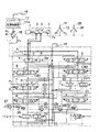
図1は、本発明に係る油圧作業機械の圧抜き装置を油圧ショベルに適用した場合の第一の実施形態を示したものである。なお、本実施形態では、バケットシリンダを取り外してオプションとしての圧砕機を取り付けるにあたり、そのバケットシリンダ用の油圧管路に閉じ込められた圧力を開放する場合を例に取り説明する。
【0014】
同図において、エンジン1によって第一のメインポンプ2、第二のメインポンプ3及びパイロットポンプ4がそれぞれ駆動する。
【0015】
メインポンプ2,3から吐出される作動油は、走行直進弁5を介し図中左側のセンターバイパスラインCB1上に配設された右走行モータ用コントロールバルブ6、バケットシリンダ用コントロールバルブ7、ブームシリンダ用コントロールバルブ8に供給されるとともに、図中右側のセンターバイパスラインCB2上の配設された左走行モータ用コントロールバルブ9、旋回モータ用コントロールバルブ10、アームシリンダ用コントロールバルブ11に供給される。
【0016】
圧抜き対象となるバケットシリンダ用コントロールバルブ7は、操作レバー12を備えたリモコン弁13から導出されるパイロット圧P1またはP2が、バケットシリンダ用コントロールバルブ7のいずれか一方のパイロットポートに作用することによって、中立位置イからロ位置またはハ位置に切り換わるようになっている。
【0017】
ロ位置では、作動油がバケットシリンダ14のヘッド側に供給されてロッドが伸長し、ロッド側作動油はタンク15に戻される。これとは逆に、ハ位置では作動油がバケットシリンダ14のロッド側に供給されてロッドが縮小され、ヘッド側作動油がタンク15に戻される。なお、パイロット圧が作用しないときには、バケット用コントロールバルブ7の両側に配置されたばねの付勢力によってスプールは中立位置イに戻されるようになっている。
【0018】
また、上記走行直進弁5は、通常、ニ位置とホ位置との間で切り換わるように構成されており、走行系とフロントアタッチメント,旋回系との連動中に一方のメインポンプ吐出油を左右の走行モータに等しく供給して走行直進性を保つようになっている。本実施形態ではその走行直進弁5に、タンク連通位置としてのヘ位置を第三の切換位置として追加している。
【0019】
圧抜きを指示する操作体としての圧抜きスイッチ19を押下すると、コントローラ17は電磁比例弁18の二次圧P5を例えば15kg/cm2に設定することにより、走行直進弁5をヘ位置に切り換える。それにより、ポート5b及び5cがそれぞれタンク15と連通しメインポンプ2及び3から吐出される作動油がそれぞれタンク15に戻される。
【0020】
なお、上述した圧抜きスイッチ19、コントローラ17及び電磁比例弁18は切換手段とみなすことができ、その切換手段と走行直進弁5は圧抜き手段とみなすことができる。
【0021】
次に、上記構成を有する油圧回路の動作について説明する。
【0022】
エンジン1を始動させると、第一のメインポンプ2、第二のメインポンプ3及びパイロットポンプ4がそれぞれ駆動し、第一のメインポンプ2から吐出される作動油はセンターバイパスラインCB2側に流れ、第二のメインポンプ3から吐出される作動油は、センターバイパスラインCB1側に流れ、さらに、パイロットポンプ4から導出される油圧P3は、リモコン弁13及び電磁比例弁18にそれぞれ供給される。
【0023】
この状態で、圧抜きスイッチ19を閉じると、二次圧P5が走行直進弁5のパイロットポート5aに作用し、走行直進弁5はヘ位置に切り換わる。それにより第一のメインポンプ2及び第二のメインポンプ3から吐出される作動油はそれぞれポート5b及び5cからタンク15に流れる。従って、エンジン1の作動によりメインポンプ2が駆動されているにも拘らずセンターバイパスラインCB1を流れる作動油が低圧となる。
【0024】
一方、パイロットポンプ4から吐出される油圧P3については所定の圧力が確保されているため、圧抜き対象となるバケットシリンダ用コントロールバルブ7を操作することができる。すなわち、バケットシリンダ用コントロールバルブ7を中立位置イからハ位置に切り換え、バケットシリンダ14の例えばヘッド側油路14bに閉じ込められている圧力をタンク15に逃がすことができる。
【0025】
この状態で、バケットシリンダ14を油圧管路14a及び14bから取り外しても管路内の圧力が既に開放されているため、作動油が噴出することがない。従ってオプションとしての圧砕機の装着を簡便に行うことができる。
【0026】
また、上述した実施形態では、コントロールバルブ群のさらに上流側に位置している走行直進弁5に、タンク15と連通し得るタンク連通路(ヘ位置)を内蔵しているため、回路内のいずれのアクチュエータに対して圧抜きを行う場合であっても、特別に切換弁を設けることなく、その走行直進弁5をヘ位置に切り換える操作のみでメインポンプ2,3から吐出される作動油の圧力を低下させることができる。
【0027】
なお、センターバイパスラインCB1におけるブームシリンダ用コントロールバルブ8の下流側には、常時開のカット弁20が設けられている。このカット弁20は開動作でタンク15と連通し、また、閉動作でアーム合流弁21に向けて作動油を流しアームシリンダ用コントロールバルブ11に供給する作動油の流量を高めることができるようになっている。
【0028】
一方、センターバイパスラインCB2における旋回モータ用コントロールバルブ10とアームシリンダ11との間の管路から分岐してカット弁22が設けられ、このカット弁22は、開動作でタンク15と連通し、また、閉動作でブーム合流弁23に向けて作動油を流しブームシリンダ用コントロールバルブ8に供給する作動油の流量を高めることができるようになっている。
【0029】
また、図2〜図4は本発明の圧抜き装置の他の実施形態を示したものである。同図においては、メンテナンス時にブームシリンダを取り外す場合を例に取り説明する。なお、同図において図1と同じ構成要素については同一符号を付してその説明を省略する。
【0030】
図2は、図1に示したタンク連通路を内蔵した走行直進弁5を必要とせず、従来の走行直進回路を利用してソフトウエア的に圧抜きを行うことができるようにしたものである。
【0031】
この構成では、コントローラ17に切換制御部17aが設けられている。この切換制御部17aは、圧抜きスイッチ19が押下された際に、通常の合流制御時には閉動作するカット弁20,22を強制的に開動作させるようになっている。
【0032】
なお、25はブーム操作レバー、26はリモコン弁であり、27はそのブーム操作レバー25によって操作されるブームシリンダである。
【0033】
まず、圧抜きが行われない場合において、メインポンプ2及び3から吐出される作動油の流れを図3中に太線で示す。メインポンプ2から吐出される作動油は左走行モータ用コントロールバルブ9から旋回モータ用コントロールバルブ10に流れるが、その下流側のカット弁22は合流制御時に閉動作しているため、作動油はブーム合流弁23に流れ、ブームシリンダ27のヘッド側油圧配管27aと合流する。
【0034】
一方、メインポンプ3から吐出される作動油については、走行直進弁5′から右走行モータ用コントロールバルブ6、バケットシリンダ用コントロールバルブ7の各センターバイパスを通してブームシリンダ用コントロールバルブ8に流れる。
【0035】
このとき、ブーム操作レバー25を操作してブームシリンダ用コントロールバルブ8を中立位置であるト位置からチ位置に切り換えると、ブームシリンダ用コントロールバルブ8のセンターバイパスがブロックされ、カット弁20には作動油が流れなくなる。従って、この動作においてはメインポンプ2及び3から吐出される作動油はブームシリンダ用コントロールバルブ8の上流側でタンク15に抜けることができず、回路圧が立ってしまうことになる。
【0036】
これに対して、本発明では、図4に示すように、操作体としての圧抜きスイッチ19の押下に基づいて電磁比例弁18から出力される二次圧P4が走行直進弁5′のパイロットポート5aに与えられる。それにより、走行直進弁5′がニ位置(第一の位置)からホ位置(第二の位置)に切り換えられメインポンプ2及び3から吐出される作動油が合流される。同時に、圧抜きスイッチ19の押下に基づいて処理を開始する切換制御部17aが、カット弁22を強制的に開いて圧抜きを行っている。
【0037】
それにより、メインポンプ2及び3から吐出される作動油はそれぞれ走行直進弁5′にて合流し、左走行モータ用コントロールバルブ9及び旋回モータ用コントロールバルブ10の各センターバイパスを通過し、カット弁22を通してタンク15に抜けることができる。なお、上記圧抜きスイッチ19、切換制御部17a及び電磁比例弁18は切換制御手段とみなすことができ、その切換制御手段と走行直進弁5′及びカット弁20,22は圧抜き手段を構成する。
【0038】
また、センターバイパスラインCB2側に接続されているアクチュエータ、例えば旋回モータ用コントロールバルブ10に接続されているアクチュエータを取り外す場合には、カット弁22の開弁動作に代えてセンターバイパスラインCB1側のカット弁20を開くことにより圧抜きを行うことになる。
【0039】
このように、上記第二の実施形態では、メインポンプ2、3から吐出される作動油は、センターバイパスラインCB1に設けられているカット弁20,センターバイパスラインCB2に設けられているカット弁22のいずれか一方を開弁動作させて作動油をタンク15に戻しつつ、パイロットポンプ4から導出されるパイロット圧で圧抜き対象となる油圧式コントロールバルブを操作し、閉じ込め圧が発生している油圧管路をタンク15に連通させて圧力を開放することができる。
【0040】
なお、上記圧抜きを行う際にはメインポンプ2,3の吐出流量を低下させることが好ましく、加えて、エンジン1の回転数を低下させることが好ましい。
【0041】
また、本発明の圧抜き手段は、上記第一の実施形態では既存の走行直進弁5に、タンク連通流路を内蔵する構成であったが、これに限らず、走行直進弁5の上流側にアンロード弁を設け作動油をタンクに戻すように構成することもできる。
【0042】
また、本発明の油圧作業機械は、上記実施形態では油圧ショベルに適用したが、これに限らず、油圧クレーン、ブルドーザ等にも適用することができる。
【0043】
【発明の効果】
以上説明したことから明らかなように、請求項1の本発明によれば、補助油圧源を備えることなく、コントロールバルブを操作可能にして油圧管路内に閉じこめられた圧力を開放することができる。
【0044】
また、請求項2の本発明によれば、メインポンプと油圧式方向制御弁との間に設けられている走行直進弁等の切換弁を利用して圧抜きを行うため、新たな弁を設けることなく圧抜きを行うことができるという長所を有する。
【0045】
請求項3の本発明によれば、既存の回路を利用してソフトウエア的に圧抜きを行うことができるという長所を有する。
【図面の簡単な説明】
【図1】本発明に係る圧抜き回路を油圧ショベルに適用した第一の実施形態を示す油圧回路図である。
【図2】本発明に係る圧抜き回路を油圧ショベルに適用した第二の実施形態を示す油圧回路図である。
【図3】図2に示す油圧回路について圧抜き動作を説明するための説明図である。
【図4】図2に示す油圧回路について圧抜き動作を説明するための説明図である。
【符号の説明】
1 エンジン
2 第一のメインポンプ
3 第二のメインポンプ
4 パイロットポンプ
5 走行直進弁
7 バケット用コントロールバルブ
15 作動油タンク
16 切換スイッチ
17 電磁切換弁
19 圧抜きスイッチ
20,21 カット弁[0001]
TECHNICAL FIELD OF THE INVENTION
The present invention relates to a pressure relief device and a pressure relief method for a hydraulic working machine, such as a hydraulic shovel, that can release pressure trapped in piping during replacement or maintenance of an attachment.
[0002]
[Prior art]
2. Description of the Related Art Conventionally, in a hydraulic excavator having a control valve operated by hydraulic pilot pressure, for example, a bucket as an attachment may be replaced with an optional crusher, and at this time, the attachment is removed from a hydraulic pipeline. At this time, since the pressure is confined in the hydraulic pipeline, when the attachment is removed, the pressure is released to the outside at a stretch, and the hydraulic oil is ejected.
[0003]
Therefore, in order to release the pressure trapped in the hydraulic pipeline, it is necessary to return the hydraulic oil discharged from the hydraulic pump to the tank and release the pressure. Specifically, an operation is performed in which the spool of the control valve is moved to switch to a hydraulic line capable of controlling pressure release.
[0004]
[Problems to be solved by the invention]
However, in a so-called hydraulic control valve in which the spool of the control valve is operated by the pilot pressure, the engine must be started in order to drive the pilot pump which is the pressure source of the pilot pressure. Therefore, when the engine is started, the main pump is driven in conjunction with the pilot pump, so that hydraulic oil flows through the hydraulic pipe connected to the attachment. Therefore, even when it is desired to operate only the control valve, that is, when it is desired to switch only the spool to the tank communication position and release the pressure, the circuit pressure rises due to the hydraulic oil discharged from the main pump, and the pressure is released. There is an inconvenience that it cannot be performed.
[0005]
Therefore, an accumulator is added to the pilot pressure line that operates the control valve as an auxiliary hydraulic pressure source, and even after the engine is stopped, the control valve spool is switched to the tank communication position using the hydraulic pressure accumulated in the accumulator. However, in this case, the configuration of the circuit becomes complicated, and an increase in cost due to the addition of an accumulator is inevitable.
[0006]
The present invention has been made in consideration of the problems in the conventional hydraulic circuit as described above, and can operate the control valve to release the pressure trapped in the pipe without providing an auxiliary hydraulic power source. An object of the present invention is to provide a pressure relief device and a pressure relief method for a hydraulic working machine.
[0007]
[Means for Solving the Problems]
According to the present invention, the main pump and the pilot pump are driven by the start of the engine, the hydraulic oil discharged from the main pump is supplied to the actuator via a hydraulic directional control valve, and the pilot pressure discharged from the pilot pump is hydraulically controlled. In a hydraulic working machine used for operation of a directional control valve, an operating body for instructing depressurization and a pilot pressure to be introduced to the hydraulic directional control valve when depressurizing is instructed by the operating body while securing Pressurizing means for connecting the supply path of the hydraulic oil discharged from the main pump to the tank on the near side of the hydraulic directional control valve to reduce the hydraulic pressure to a low level. is there.
[0008]
The present invention provides a depressurizing device having the above configuration, further comprising a switching valve having a merging position and a non-merging position between the plurality of main pumps and the hydraulic directional control valve, wherein the switching valve is operated by the main pump. A pressure relief device for a hydraulic working machine having a tank communication path for connecting an oil supply path to a tank and switching means for switching a switching valve to a tank communication position when pressure release is instructed by an operating body.
[0009]
The present invention provides a pressure relief device having the above configuration, wherein a hydraulic directional control valve provided on a plurality of center bypass lines, a cut valve for releasing hydraulic oil from a main pump in a valve open state to a tank, A traveling straight valve having a first position leading only to the center bypass line and a second position leading to both center bypass lines, and moving the traveling straight valve to the second position when pressure release is instructed by the operating body. And a switching control means for opening the cut valve on the other center bypass line.
[0010]
According to the depressurizing method of the present invention, the main pump and the pilot pump are driven by the start of the engine, and the operating oil discharged from the main pump is supplied to the actuator via the hydraulic directional control valve, and the pilot oil discharged from the pilot pump is The pressure is controlled by a hydraulic working machine that is used to operate a hydraulic directional control valve.
When pressure release is instructed, the supply path of hydraulic oil discharged from the main pump is communicated with the tank on the near side of the hydraulic directional control valve to reduce the pressure of hydraulic oil, and the pilot discharged from the pilot pump The gist of the present invention is to operate a hydraulic directional control valve with pressure to release a pressure by communicating an oil passage in which a confining pressure is generated with a tank.
[0011]
In the above pressure release method, it is preferable to release the confinement pressure while reducing the discharge flow rate of the main pump. Further, it is preferable to release the confinement pressure while the engine speed is reduced.
[0012]
BEST MODE FOR CARRYING OUT THE INVENTION
Hereinafter, the present invention will be described in detail based on an embodiment shown in the drawings.
[0013]
FIG. 1 shows a first embodiment in which a pressure relief device for a hydraulic working machine according to the present invention is applied to a hydraulic shovel. In addition, in this embodiment, when removing a bucket cylinder and installing an optional crusher, the case where the pressure confined in the hydraulic line for the bucket cylinder is released will be described as an example.
[0014]
In the figure, a first
[0015]
Hydraulic oil discharged from the
[0016]
In the bucket
[0017]
At the b position, the hydraulic oil is supplied to the head side of the
[0018]
The traveling
[0019]
Pressing the
[0020]
The above-described
[0021]
Next, the operation of the hydraulic circuit having the above configuration will be described.
[0022]
When the
[0023]
In this state, closing the
[0024]
On the other hand, the oil pressure P 3 which is discharged from the
[0025]
In this state, even if the
[0026]
Further, in the above-described embodiment, since the straight traveling
[0027]
A normally
[0028]
On the other hand, a
[0029]
2 to 4 show another embodiment of the depressurizing device of the present invention. In the figure, a case where the boom cylinder is removed during maintenance will be described as an example. In the figure, the same components as those in FIG. 1 are denoted by the same reference numerals, and description thereof is omitted.
[0030]
FIG. 2 does not require the straight-running
[0031]
In this configuration, the
[0032]
[0033]
First, the flow of hydraulic oil discharged from the
[0034]
On the other hand, the hydraulic oil discharged from the
[0035]
At this time, when the
[0036]
In contrast, in the present invention, as shown in FIG. 4, the pilot secondary pressure P 4 that is output from the solenoid
[0037]
Thereby, the hydraulic oil discharged from the
[0038]
When removing the actuator connected to the center bypass line CB2, for example, the actuator connected to the swing
[0039]
As described above, in the second embodiment, the hydraulic oil discharged from the
[0040]
When performing the pressure release, it is preferable to decrease the discharge flow rate of the
[0041]
In the first embodiment, the depressurizing means of the present invention has a configuration in which a tank communication flow path is built in the existing traveling
[0042]
Further, the hydraulic working machine of the present invention is applied to a hydraulic excavator in the above embodiment, but is not limited to this, and can be applied to a hydraulic crane, a bulldozer and the like.
[0043]
【The invention's effect】
As is apparent from the above description, according to the first aspect of the present invention, the control valve can be operated and the pressure trapped in the hydraulic pipeline can be released without providing the auxiliary hydraulic pressure source. .
[0044]
According to the second aspect of the present invention, a new valve is provided because pressure is released by using a switching valve such as a straight traveling valve provided between the main pump and the hydraulic directional control valve. It has the advantage that depressurization can be performed without any pressure.
[0045]
According to the third aspect of the present invention, there is an advantage that depressurization can be performed by software using an existing circuit.
[Brief description of the drawings]
FIG. 1 is a hydraulic circuit diagram showing a first embodiment in which a pressure relief circuit according to the present invention is applied to a hydraulic shovel.
FIG. 2 is a hydraulic circuit diagram showing a second embodiment in which the pressure relief circuit according to the present invention is applied to a hydraulic shovel.
FIG. 3 is an explanatory diagram for explaining a pressure release operation of the hydraulic circuit shown in FIG. 2;
FIG. 4 is an explanatory diagram illustrating a pressure relief operation of the hydraulic circuit illustrated in FIG. 2;
[Explanation of symbols]
DESCRIPTION OF
Claims (6)
圧抜きを指示する操作体と、
その操作体によって圧抜きが指示された際に、前記油圧式方向制御弁へ導入するパイロット圧は確保しつつ、前記メインポンプから吐出される作動油の供給路を前記油圧式方向制御弁の手前側でタンクと連通させて作動油を低圧にする圧抜き手段と、を備えてなることを特徴とする油圧作業機械の圧抜き装置。When the engine is started, the main pump and the pilot pump are driven. The hydraulic oil discharged from the main pump is supplied to an actuator via a hydraulic directional control valve, and the pilot pressure discharged from the pilot pump is controlled in the hydraulic direction. In a hydraulic working machine provided for operation of a control valve,
An operation tool for instructing depressurization,
When pressure release is instructed by the operating body, the pilot pressure to be introduced to the hydraulic directional control valve is secured, and the supply path of the hydraulic oil discharged from the main pump is positioned before the hydraulic directional control valve. And a depressurizing means that communicates with the tank on the side to reduce the operating oil pressure.
圧抜きが指示された際に、前記メインポンプから吐出される作動油の供給路を前記油圧式方向制御弁の手前側でタンクと連通させて作動油の圧力を低下させ、前記パイロットポンプから吐出されるパイロット圧で前記油圧式方向制御弁を操作し、閉じ込め圧が発生している油路を前記タンクと連通させて圧力を開放することを特徴とする油圧作業機械の圧抜き方法。When the engine is started, the main pump and the pilot pump are driven. The hydraulic oil discharged from the main pump is supplied to an actuator via a hydraulic directional control valve, and the pilot pressure discharged from the pilot pump is controlled in the hydraulic direction. In a hydraulic working machine provided for operation of a control valve,
When depressurization is instructed, the supply path of the hydraulic oil discharged from the main pump is communicated with the tank on the front side of the hydraulic directional control valve to reduce the pressure of the hydraulic oil and discharged from the pilot pump. Operating the hydraulic directional control valve with the pilot pressure to communicate the oil passage in which the confining pressure is generated with the tank to release the pressure, thereby releasing the pressure of the hydraulic working machine.
Priority Applications (1)
| Application Number | Priority Date | Filing Date | Title |
|---|---|---|---|
| JP22908798A JP3597708B2 (en) | 1998-08-13 | 1998-08-13 | Depressurizing device and depressurizing method for hydraulic working machine |
Applications Claiming Priority (1)
| Application Number | Priority Date | Filing Date | Title |
|---|---|---|---|
| JP22908798A JP3597708B2 (en) | 1998-08-13 | 1998-08-13 | Depressurizing device and depressurizing method for hydraulic working machine |
Publications (2)
| Publication Number | Publication Date |
|---|---|
| JP2000065003A JP2000065003A (en) | 2000-03-03 |
| JP3597708B2 true JP3597708B2 (en) | 2004-12-08 |
Family
ID=16886557
Family Applications (1)
| Application Number | Title | Priority Date | Filing Date |
|---|---|---|---|
| JP22908798A Expired - Lifetime JP3597708B2 (en) | 1998-08-13 | 1998-08-13 | Depressurizing device and depressurizing method for hydraulic working machine |
Country Status (1)
| Country | Link |
|---|---|
| JP (1) | JP3597708B2 (en) |
Cited By (2)
| Publication number | Priority date | Publication date | Assignee | Title |
|---|---|---|---|---|
| CN101644288A (en) * | 2008-08-08 | 2010-02-10 | 沃尔沃建造设备控股(瑞典)有限公司 | Hydraulic flow sharing system for excavating and pipe laying work |
| JP7436301B2 (en) | 2020-06-19 | 2024-02-21 | 日立建機株式会社 | construction machinery |
Families Citing this family (5)
| Publication number | Priority date | Publication date | Assignee | Title |
|---|---|---|---|---|
| JP2003004005A (en) * | 2001-06-22 | 2003-01-08 | Kobelco Contstruction Machinery Ltd | Hydraulic control circuit of construction machine |
| JP4294563B2 (en) * | 2004-09-10 | 2009-07-15 | 日立建機株式会社 | Work machine |
| KR101156859B1 (en) * | 2004-12-29 | 2012-06-20 | 두산인프라코어 주식회사 | Apparatus for preventing unexpected operation of an excavator |
| JP2016217087A (en) * | 2015-05-26 | 2016-12-22 | 日立建機株式会社 | Construction machine |
| CN111733922A (en) * | 2020-07-06 | 2020-10-02 | 上海三一重机股份有限公司 | Excavator flow distribution system and excavator |
-
1998
- 1998-08-13 JP JP22908798A patent/JP3597708B2/en not_active Expired - Lifetime
Cited By (3)
| Publication number | Priority date | Publication date | Assignee | Title |
|---|---|---|---|---|
| CN101644288A (en) * | 2008-08-08 | 2010-02-10 | 沃尔沃建造设备控股(瑞典)有限公司 | Hydraulic flow sharing system for excavating and pipe laying work |
| CN101644288B (en) * | 2008-08-08 | 2014-04-23 | 沃尔沃建造设备控股(瑞典)有限公司 | Hydraulic flow sharing system for excavating and pipe laying work |
| JP7436301B2 (en) | 2020-06-19 | 2024-02-21 | 日立建機株式会社 | construction machinery |
Also Published As
| Publication number | Publication date |
|---|---|
| JP2000065003A (en) | 2000-03-03 |
Similar Documents
| Publication | Publication Date | Title |
|---|---|---|
| JP4193830B2 (en) | Hydraulic control device for work machine | |
| JP4724664B2 (en) | Hydraulic system for work machines | |
| KR101767857B1 (en) | Hydraulic system for work vehicle | |
| JP3816893B2 (en) | Hydraulic drive | |
| WO2013005393A1 (en) | Construction machine | |
| JP2006220177A (en) | Hydraulic shovel | |
| JP3597708B2 (en) | Depressurizing device and depressurizing method for hydraulic working machine | |
| WO2012017622A1 (en) | Construction machine comprising hydraulic circuit | |
| KR20110072719A (en) | Sudden turning prevention system for construction machinery | |
| JP4100690B2 (en) | Hydraulic circuit for optional equipment for heavy equipment using spool for boom merging | |
| KR100797315B1 (en) | Hydraulic apparatus for controlling complex work mode of travel and front works | |
| JP2003184815A (en) | Hydraulic controlled device of construction machine and hydraulic controlled device of hydraulic power shovel | |
| JP3607529B2 (en) | Hydraulic control device for construction machinery | |
| JP3076210B2 (en) | Hydraulic drive for construction machinery | |
| JP7152968B2 (en) | hydraulic excavator drive system | |
| JPH10152866A (en) | Fluid pressure circuit | |
| JP7001554B2 (en) | Hydraulic excavator with crane function | |
| JP2004116727A (en) | Drive control device and selector valve device of hydraulic machinery | |
| JP3595148B2 (en) | Regeneration circuit | |
| JP5498325B2 (en) | Hydraulic control circuit for work machines | |
| JP7268435B2 (en) | Working machine hydraulic drive | |
| WO2023286530A1 (en) | Construction machine | |
| KR101970110B1 (en) | Make up oil flow control device of swing motor | |
| JP3992611B2 (en) | Backhoe hydraulic circuit structure | |
| JP2006257713A (en) | Oil pressure control circuit of work machine |
Legal Events
| Date | Code | Title | Description |
|---|---|---|---|
| A977 | Report on retrieval |
Free format text: JAPANESE INTERMEDIATE CODE: A971007 Effective date: 20040629 |
|
| TRDD | Decision of grant or rejection written | ||
| A01 | Written decision to grant a patent or to grant a registration (utility model) |
Free format text: JAPANESE INTERMEDIATE CODE: A01 Effective date: 20040824 |
|
| A61 | First payment of annual fees (during grant procedure) |
Free format text: JAPANESE INTERMEDIATE CODE: A61 Effective date: 20040909 |
|
| R150 | Certificate of patent or registration of utility model |
Free format text: JAPANESE INTERMEDIATE CODE: R150 |
|
| FPAY | Renewal fee payment (event date is renewal date of database) |
Free format text: PAYMENT UNTIL: 20070917 Year of fee payment: 3 |
|
| FPAY | Renewal fee payment (event date is renewal date of database) |
Free format text: PAYMENT UNTIL: 20080917 Year of fee payment: 4 |
|
| FPAY | Renewal fee payment (event date is renewal date of database) |
Free format text: PAYMENT UNTIL: 20080917 Year of fee payment: 4 |
|
| FPAY | Renewal fee payment (event date is renewal date of database) |
Free format text: PAYMENT UNTIL: 20090917 Year of fee payment: 5 |
|
| FPAY | Renewal fee payment (event date is renewal date of database) |
Free format text: PAYMENT UNTIL: 20090917 Year of fee payment: 5 |
|
| FPAY | Renewal fee payment (event date is renewal date of database) |
Free format text: PAYMENT UNTIL: 20100917 Year of fee payment: 6 |
|
| FPAY | Renewal fee payment (event date is renewal date of database) |
Free format text: PAYMENT UNTIL: 20100917 Year of fee payment: 6 |
|
| FPAY | Renewal fee payment (event date is renewal date of database) |
Free format text: PAYMENT UNTIL: 20110917 Year of fee payment: 7 |
|
| FPAY | Renewal fee payment (event date is renewal date of database) |
Free format text: PAYMENT UNTIL: 20120917 Year of fee payment: 8 |
|
| FPAY | Renewal fee payment (event date is renewal date of database) |
Free format text: PAYMENT UNTIL: 20120917 Year of fee payment: 8 |
|
| FPAY | Renewal fee payment (event date is renewal date of database) |
Free format text: PAYMENT UNTIL: 20130917 Year of fee payment: 9 |
|
| EXPY | Cancellation because of completion of term |