EP1304473A2 - Intake arrangement for multi-cylinder engine - Google Patents
Intake arrangement for multi-cylinder engine Download PDFInfo
- Publication number
- EP1304473A2 EP1304473A2 EP02023605A EP02023605A EP1304473A2 EP 1304473 A2 EP1304473 A2 EP 1304473A2 EP 02023605 A EP02023605 A EP 02023605A EP 02023605 A EP02023605 A EP 02023605A EP 1304473 A2 EP1304473 A2 EP 1304473A2
- Authority
- EP
- European Patent Office
- Prior art keywords
- protector
- branch
- intake
- arrangement
- split
- Prior art date
- Legal status (The legal status is an assumption and is not a legal conclusion. Google has not performed a legal analysis and makes no representation as to the accuracy of the status listed.)
- Granted
Links
- 230000001012 protector Effects 0.000 claims abstract description 98
- 239000000446 fuel Substances 0.000 claims abstract description 75
- 238000002485 combustion reaction Methods 0.000 claims abstract description 11
- 239000011324 bead Substances 0.000 claims description 21
- 239000000463 material Substances 0.000 claims description 10
- 239000011347 resin Substances 0.000 claims description 10
- 229920005989 resin Polymers 0.000 claims description 10
- 238000011144 upstream manufacturing Methods 0.000 claims description 10
- 230000002093 peripheral effect Effects 0.000 claims description 9
- 230000006698 induction Effects 0.000 claims description 8
- 238000001816 cooling Methods 0.000 claims description 4
- 238000005452 bending Methods 0.000 claims description 3
- 230000001939 inductive effect Effects 0.000 claims 2
- 230000000712 assembly Effects 0.000 description 5
- 238000000429 assembly Methods 0.000 description 5
- 230000008878 coupling Effects 0.000 description 4
- 238000010168 coupling process Methods 0.000 description 4
- 238000005859 coupling reaction Methods 0.000 description 4
- 239000002828 fuel tank Substances 0.000 description 2
- 238000002347 injection Methods 0.000 description 2
- 239000007924 injection Substances 0.000 description 2
- 229910052751 metal Inorganic materials 0.000 description 2
- 239000002184 metal Substances 0.000 description 2
- 239000007769 metal material Substances 0.000 description 2
- 238000003466 welding Methods 0.000 description 2
- 229910052782 aluminium Inorganic materials 0.000 description 1
- XAGFODPZIPBFFR-UHFFFAOYSA-N aluminium Chemical compound [Al] XAGFODPZIPBFFR-UHFFFAOYSA-N 0.000 description 1
- 230000006866 deterioration Effects 0.000 description 1
- 238000010586 diagram Methods 0.000 description 1
- 238000006073 displacement reaction Methods 0.000 description 1
- 238000004519 manufacturing process Methods 0.000 description 1
- 230000004048 modification Effects 0.000 description 1
- 238000012986 modification Methods 0.000 description 1
Images


Classifications
-
- F—MECHANICAL ENGINEERING; LIGHTING; HEATING; WEAPONS; BLASTING
- F02—COMBUSTION ENGINES; HOT-GAS OR COMBUSTION-PRODUCT ENGINE PLANTS
- F02M—SUPPLYING COMBUSTION ENGINES IN GENERAL WITH COMBUSTIBLE MIXTURES OR CONSTITUENTS THEREOF
- F02M61/00—Fuel-injectors not provided for in groups F02M39/00 - F02M57/00 or F02M67/00
- F02M61/14—Arrangements of injectors with respect to engines; Mounting of injectors
- F02M61/145—Arrangements of injectors with respect to engines; Mounting of injectors the injection nozzle opening into the air intake conduit
-
- F—MECHANICAL ENGINEERING; LIGHTING; HEATING; WEAPONS; BLASTING
- F02—COMBUSTION ENGINES; HOT-GAS OR COMBUSTION-PRODUCT ENGINE PLANTS
- F02M—SUPPLYING COMBUSTION ENGINES IN GENERAL WITH COMBUSTIBLE MIXTURES OR CONSTITUENTS THEREOF
- F02M35/00—Combustion-air cleaners, air intakes, intake silencers, or induction systems specially adapted for, or arranged on, internal-combustion engines
- F02M35/10—Air intakes; Induction systems
- F02M35/10091—Air intakes; Induction systems characterised by details of intake ducts: shapes; connections; arrangements
- F02M35/10111—Substantially V-, C- or U-shaped ducts in direction of the flow path
-
- F—MECHANICAL ENGINEERING; LIGHTING; HEATING; WEAPONS; BLASTING
- F02—COMBUSTION ENGINES; HOT-GAS OR COMBUSTION-PRODUCT ENGINE PLANTS
- F02M—SUPPLYING COMBUSTION ENGINES IN GENERAL WITH COMBUSTIBLE MIXTURES OR CONSTITUENTS THEREOF
- F02M35/00—Combustion-air cleaners, air intakes, intake silencers, or induction systems specially adapted for, or arranged on, internal-combustion engines
- F02M35/10—Air intakes; Induction systems
- F02M35/10091—Air intakes; Induction systems characterised by details of intake ducts: shapes; connections; arrangements
- F02M35/10144—Connections of intake ducts to each other or to another device
-
- F—MECHANICAL ENGINEERING; LIGHTING; HEATING; WEAPONS; BLASTING
- F02—COMBUSTION ENGINES; HOT-GAS OR COMBUSTION-PRODUCT ENGINE PLANTS
- F02M—SUPPLYING COMBUSTION ENGINES IN GENERAL WITH COMBUSTIBLE MIXTURES OR CONSTITUENTS THEREOF
- F02M35/00—Combustion-air cleaners, air intakes, intake silencers, or induction systems specially adapted for, or arranged on, internal-combustion engines
- F02M35/10—Air intakes; Induction systems
- F02M35/10209—Fluid connections to the air intake system; their arrangement of pipes, valves or the like
- F02M35/10216—Fuel injectors; Fuel pipes or rails; Fuel pumps or pressure regulators
-
- F—MECHANICAL ENGINEERING; LIGHTING; HEATING; WEAPONS; BLASTING
- F02—COMBUSTION ENGINES; HOT-GAS OR COMBUSTION-PRODUCT ENGINE PLANTS
- F02M—SUPPLYING COMBUSTION ENGINES IN GENERAL WITH COMBUSTIBLE MIXTURES OR CONSTITUENTS THEREOF
- F02M35/00—Combustion-air cleaners, air intakes, intake silencers, or induction systems specially adapted for, or arranged on, internal-combustion engines
- F02M35/10—Air intakes; Induction systems
- F02M35/10314—Materials for intake systems
- F02M35/10321—Plastics; Composites; Rubbers
-
- F—MECHANICAL ENGINEERING; LIGHTING; HEATING; WEAPONS; BLASTING
- F02—COMBUSTION ENGINES; HOT-GAS OR COMBUSTION-PRODUCT ENGINE PLANTS
- F02M—SUPPLYING COMBUSTION ENGINES IN GENERAL WITH COMBUSTIBLE MIXTURES OR CONSTITUENTS THEREOF
- F02M35/00—Combustion-air cleaners, air intakes, intake silencers, or induction systems specially adapted for, or arranged on, internal-combustion engines
- F02M35/10—Air intakes; Induction systems
- F02M35/1034—Manufacturing and assembling intake systems
- F02M35/10354—Joining multiple sections together
-
- F—MECHANICAL ENGINEERING; LIGHTING; HEATING; WEAPONS; BLASTING
- F02—COMBUSTION ENGINES; HOT-GAS OR COMBUSTION-PRODUCT ENGINE PLANTS
- F02M—SUPPLYING COMBUSTION ENGINES IN GENERAL WITH COMBUSTIBLE MIXTURES OR CONSTITUENTS THEREOF
- F02M35/00—Combustion-air cleaners, air intakes, intake silencers, or induction systems specially adapted for, or arranged on, internal-combustion engines
- F02M35/10—Air intakes; Induction systems
- F02M35/104—Intake manifolds
- F02M35/112—Intake manifolds for engines with cylinders all in one line
-
- F—MECHANICAL ENGINEERING; LIGHTING; HEATING; WEAPONS; BLASTING
- F02—COMBUSTION ENGINES; HOT-GAS OR COMBUSTION-PRODUCT ENGINE PLANTS
- F02M—SUPPLYING COMBUSTION ENGINES IN GENERAL WITH COMBUSTIBLE MIXTURES OR CONSTITUENTS THEREOF
- F02M69/00—Low-pressure fuel-injection apparatus ; Apparatus with both continuous and intermittent injection; Apparatus injecting different types of fuel
- F02M69/46—Details, component parts or accessories not provided for in, or of interest apart from, the apparatus covered by groups F02M69/02 - F02M69/44
- F02M69/462—Arrangement of fuel conduits, e.g. with valves for maintaining pressure in the pipes after the engine being shut-down
- F02M69/465—Arrangement of fuel conduits, e.g. with valves for maintaining pressure in the pipes after the engine being shut-down of fuel rails
-
- F—MECHANICAL ENGINEERING; LIGHTING; HEATING; WEAPONS; BLASTING
- F02—COMBUSTION ENGINES; HOT-GAS OR COMBUSTION-PRODUCT ENGINE PLANTS
- F02M—SUPPLYING COMBUSTION ENGINES IN GENERAL WITH COMBUSTIBLE MIXTURES OR CONSTITUENTS THEREOF
- F02M2200/00—Details of fuel-injection apparatus, not otherwise provided for
- F02M2200/18—Fuel-injection apparatus having means for maintaining safety not otherwise provided for
- F02M2200/185—Fuel-injection apparatus having means for maintaining safety not otherwise provided for means for improving crash safety
-
- F—MECHANICAL ENGINEERING; LIGHTING; HEATING; WEAPONS; BLASTING
- F05—INDEXING SCHEMES RELATING TO ENGINES OR PUMPS IN VARIOUS SUBCLASSES OF CLASSES F01-F04
- F05C—INDEXING SCHEME RELATING TO MATERIALS, MATERIAL PROPERTIES OR MATERIAL CHARACTERISTICS FOR MACHINES, ENGINES OR PUMPS OTHER THAN NON-POSITIVE-DISPLACEMENT MACHINES OR ENGINES
- F05C2225/00—Synthetic polymers, e.g. plastics; Rubber
- F05C2225/08—Thermoplastics
Definitions
- the present invention relates to an intake arrangement for a multi-cylinder internal combustion engine of a vehicle, and more specifically to an intake arrangement made of resin material.
- the intake manifolds made of resin material have less rigidity as compared with intake manifolds made of metal material. Therefore, if an impact load is applied to the engine room upon vehicle collision and the intake manifold made of resin material may become deformed, the deformed intake manifold will be urged toward a fuel pipe adjacent thereto so that the fuel pipe is deformed. Further, the intake manifold made of resin material will be readily vibrated because of the less rigidity. If the vibration produced in the intake manifold is transmitted to a fuel injector, fuel sprayed from the fuel injector will be prevented from being directed toward a target area of the fuel injection. This will cause deterioration in combustion properties.
- an intake arrangement for an internal combustion engine of a vehicle in which a protector for a fuel pipe is used.
- the protector is deformed so as to protect a fuel pipe upon applying an impact load to the intake arrangement, such as at the occurrence of vehicle collision. Owing to the deformation of the protector, the impact load applied to the intake arrangement can be reduced, and the fuel pipe can be prevented from being deformed.
- an intake arrangement for an internal combustion engine of a vehicle which can be enhanced in rigidity by using a protector for a fuel pipe.
- the intake arrangement having the enhanced rigidity can reduce vibration caused therein, serving for preventing the fuel pipe and a fuel injector from suffering from the vibration transmitted from the intake arrangement.
- an intake arrangement for a multi-cylinder internal combustion engine of a vehicle the engine having a row of cylinders, the arrangement comprising:
- an intake arrangement for a multi-cylinder internal combustion engine of a vehicle the engine having a row of cylinders, the intake arrangement comprising:
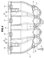
- Fig. 1 is a perspective view of an intake arrangement for an internal combustion engine, according to an embodiment of the present invention
- Fig. 2 is an front view of the intake arrangement shown in Fig. 1;
- Fig. 3 is a side view of the intake arrangement shown in Fig. 1
- Fig. 4 is a plan view of a lower branch of an intake manifold in the arrangement of Fig. 1;
- Fig. 5 is a perspective view of the intake arrangement, showing the lower branch to which a protector and a fuel pipe are mounted;
- Fig. 6 is a perspective view of the protector of Fig. 5;
- Fig. 7 is an explanatory diagram of deformation of the lower branch and the protector upon an impact load being applied to the intake manifold;
- Fig. 8 is a vertical sectional view of the engine.
- FIG. 8 shows engine 100 including cylinder block 102 and cylinder head 104.
- Four cylinders are defined in cylinder block 102 so as to be arranged in a row.
- Cylinder head 104 is disposed on the top of cylinder block 102.
- Cylinder head 104 has intake ports 106 corresponding to the cylinders.
- Intake valve 108 is disposed in each of intake ports 106 and operated to open and close intake ports 106.
- intake manifold 1 is made of resin material and allows air to be introduced to the engine cylinders.
- intake manifold 1 includes collector 2 and branch portion 3 communicated with collector 2.
- Collector 2 is disposed above cylinder head 104 of engine 100 shown in Fig. 8 and allows a main flow of the air.
- Collector 2 has a generally elongated cylindrical shape extending along the row of cylinders.
- Branch portion 3 connects collector 2 to intake port 106 of each cylinder of engine 100 and allows the main flow of air in collector 2 to be divided into branch flows each introduced into the cylinder via intake port 106.
- branch portion 3 has four branches corresponding to the four cylinders extending in a transverse direction relative to the longitudinal axis of collector 2.
- branch portion 3 has a generally U-shape.
- Branch portion 3 includes upper branch 9 and lower branch 10 which are joined with each other at bent portion 8 of the U-shape.
- Upper branch 9 has downstream end portion 11 relative to the air flow flowing through branch portion 3 into intake port 106
- lower branch 10 has upstream end portion 12 relative to the air flow.
- Downstream end portion 11 and upstream end portion 12 are joined with each other with the combined use of bolts and so-called snap-fit assemblies.
- each of the snap-fit assemblies is constituted of projection 13 and hole 15 which are engaged with each other.
- Projection 13 is formed at upstream end portion 12.
- Hole 15 is formed in tab 14 projecting from downstream end portion 11.
- lower branch 10 has bolt holes 16 for tap bolts B.
- Sleeve 17 which is made of resin material and has an internal thread, is fixed into each of bolt holes 16.
- Each of tap bolts B is screwed into sleeve 17 from a lower side of lower branch 10 upon coupling lower branch 10 with upper branch 9.
- Each of bolt holes 16 is located on the side closer to the engine than each of the snap-fit assemblies, namely, on the upper side of Fig. 4.
- Bolt holes 16 are arranged substantially in line along the longitudinal axis of collector 2.
- Lower branch 10 has a downstream end portion formed with intake port flange 19. Intake port flange 19 is mounted to cylinder head 104 of engine 100 shown in Fig. 8.
- the downstream end portion of lower branch 10, i.e., the downstream end portion of branch portion 3, allows the air to be introduced into the cylinders via intake port 106 of cylinder head 104.
- Reference numeral 18 denotes a mount hole for fuel injector 5 shown in Fig. 3.
- Protector mounts 20, 20 for mounting protector 6 are disposed on the downstream end portion of lower branch 10 but upstream of intake port flange 19.
- Protector mounts 20, 20 are disposed an outer surface of an upper side of the downstream end portion of lower branch 10.
- Protector mounts 20, 20 are spaced from and opposed to each other along the direction of the row of the engine cylinders. Namely, protector mounts 20, 20 are located on the left and right sides in Fig. 4.
- Each of protector mounts 20, 20 includes boss 21 and two opposed ribs 22. Boss 21 outward projects from the outer surface of the downstream end portion of lower branch 10 and spaced from intake port flange 19. Ribs 22 extend between boss 21 and intake port flange 19 and connect them.
- protector 6 is secured to protector mounts 20, 20 of lower branch 10 together with fuel pipe 4 having fuel injector 5.
- Fuel injector 5 is preassembled to fuel pipe 4.
- Fuel pipe 4 is connected with a fuel tank via fuel tube 7 and supplies fuel from the fuel tank to fuel injector 5.
- Fuel pipe 4 extends along the longitudinal axis of collector 2, i.e., in the direction of the row of engine cylinders.
- fuel pipe 4 has end portions 4A, 4A opposed to each other in the longitudinal direction and general portion 4B extending between end portions 4A, 4A. End portions 4A, 4A have rigidity larger than that of general portion 4B.
- Fuel pipe 4 has mount 23 which is interposed between protector 6 and protector mounts 20, 20. Fuel pipe 4 is fixed to protector mounts 20, 20 via mount 23.
- lower branch 10 includes a pair of members 25 and 26 coupled with each other and split surface 24 disposed between the pair of members 25 and 26.
- one member 25 is located on an upper side of lower branch 10 and provided with protector mount 20, and the other member 26 is located on a lower side of lower branch 10.
- one member 25 and the other member 26 are located on an upper side of the vehicle and a lower side thereof, respectively.
- Two members 25 and 26 are joined together at split surface 24 by vibration welding.
- Split surface 24 extends substantially along the flow of the air introduced into lower branch 10 and flowing to intake ports 106 of cylinder head 104 of engine 100.
- Split surface 24 is curved toward member 26, namely, downwardly as viewed in Fig. 3.
- Split surface 24 has downstream end 24A disposed at the downstream end portion of lower branch 10. Downstream end 24A is located in the lower side surface of lower branch 10 in a circumferentially opposed relation to protector mount 20 disposed on the upper side surface of lower branch 10.
- Member 25 has step 27 formed on an outer surface thereof upstream of protector mount 20.
- Member 25 has a reduced thickness on the upstream side of step 27 which is smaller than a thickness on the downstream side of step 27.
- Split surface 24 and step 27 act as a split induction portion which induces a split in branch portion 3 upon an impact load being applied to branch portion 3.
- Split surface 24 acts to divide lower branch 10 into members 25 and 26 along the branch flows in lower branch 10 as explained later.
- Step 27 acts to bend member 25 toward fuel pipe 4 as explained later.
- Upper branch 9 includes a pair of members 29 and 30 coupled with each other and split surface 28 between the pair of members 29 and 30.
- Split surface 28 extends substantially in the direction of the flow of the air introduced into upper branch 9. Two members 29 and 30 are joined together at split surface 28 by vibration welding.
- Protector 6 disposed between fuel pipe 4 and branch portion 3 has a generally L-shape as shown in Fig. 3.
- Protector 6 extends along fuel pipe 4 over the longitudinal length of fuel pipe 4 and the lateral width thereof perpendicular to the longitudinal length as shown in Fig. 5.
- protector 6 includes base wall 35 and cover wall 36 which are integrally formed with each other.
- Base wall 35 is fixed to protector mount 20 of lower branch 10.
- Cover wall 36 is bent at a predetermined angle relative to base wall 35. The predetermined angle may be about 90 degrees.
- Protector 6 also has, at opposed ends thereof, side walls 37, 37 with flanges 38, 38. Side walls 37, 37 upward extend from cover wall 36 in an opposed relation to each other and are connected with base wall 35.
- Side walls 37, 37 are substantially perpendicular to base wall 35 and cover wall 36.
- Flanges 38, 38 are outward bent at upper ends of side walls 37, 37.
- Flanges 38, 38 are integrally formed with side walls 37, 37.
- Protector 6 is formed by bending a metal sheet.
- a plurality of generally rectangular-shaped openings 39 are formed in protector 6. Openings 39 are spaced from each other in the longitudinal direction of protector 6. Each of openings 39 extends across base wall 35 and cover wall 36 in a transverse direction relative to the longitudinal direction of protector 6. A plurality of beads 40 are disposed between openings 39, which extend across base wall 35 and cover wall 36 in the transverse direction relative to the longitudinal direction of protector 6. Beads 40 have a larger length than openings 39. Beads 40 are provided by press forming so as to project from an inner surface of L-shaped protector 6, namely, project upward in Fig. 3. Beads 40 extend from an inner surface of cover wall 36 to a lesser extent than side walls 37.
- beads 40 have a height from the inner surface of cover wall 36 which is smaller than a length of side walls 37 of protector 6.
- the height of beads 40 is preset such that beads 40 can be prevented from being contacted with fuel pipe 4 before flanges 38, 38 come into contact with opposed ends 4A, 4A of fuel pipe 4 upon deformation of protector 6 as explained later.
- Cover wall 36 defines one end 39A of each opening 39 and one end 40A of each bead 40, and base wall 35 defines an opposite end of each opening 39 and an opposite end of each bead 40.
- cover wall 36 has a peripheral edge which extends in the longitudinal direction of protector 6 on an opposite side of the joint periphery connected with base wall 35.
- One end 39A of each opening 39 and one end 40A of each bead 40 are located close to the peripheral edge of cover wall 36. As shown in Fig. 6, distance L1 between one end 39A and the peripheral edge of cover wall 36 is larger than distance L2 between one end 40A and the peripheral edge of cover wall 36. In other words, one end 39A is located closer to base wall 35 than one end 40A.
- lower branch 10 is bent at step 27 of upper member 25 toward fuel pipe 4 and split along split surface 24 such that upper member 25 and lower member 26 are separated from each other at split surface 24.
- Lower branch 10 bent is in contact with protector 6 and urges protector 6 such that cover wall 36 is bent toward fuel pipe 4, i.e., leftward in Fig. 7.
- Protector 6 is plastically deformed into a bent state as shown in Fig. 7.
- fuel pipe 4 is covered by protector 6 over the longitudinal length of fuel pipe 4 and the lateral width thereof.
- protector 6 If protector 6 is further deformed to come closer to fuel pipe 4, flanges 38, 38 of protector 6 will be brought into contact with opposed ends 4A, 4A of fuel pipe 4. Even in such a condition, since opposed ends 4A, 4A have the increased rigidity, fuel pipe 4 can be prevented from being readily deformed at opposed ends 4A, 4A due to the contact with flanges 38, 38. Further, owing to the preset height of beads 40 which is smaller than that of side walls 37, 37, beads 40 can be prevented from the contact with fuel pipe 4 before flanges 38, 38 are contacted with opposed ends 4A, 4A of fuel pipe 4.
- protector 6 undergoes a relatively small impact load upon being contacted with lower branch 10, protector 6 will be free from plastic deformation and will be elastically deformed to absorb the impact energy.
- the impact energy also can be absorbed and reduced by three-stage split of branch portion 3.
- the three stages of split of branch portion 3 are as follows: at the first stage upper branch 9 and lower branch 10 are separated at bent portion 8 of branch portion 3; at the second stage lower branch 10 is bent at step 27 and separated along split surface 24; and at the third stage protector 6 is deformed by lower branch 10 bent and separated. This serves for ensuring protection of fuel pipe 4 upon application of the impact load.
- the split of lower branch 10 is conducted at step 27 and split surface 24 which act as the split induction portion. This can prevent protector mount 20, 20 from being deformed due to the impact load applied to branch portion 3. Therefore, protector 6 fixed to protector mount 20, 20 can perform protection of fuel pipe 4 upon application of the impact load.
- protector 6 With the arrangement of protector 6, the rigidity of intake manifold 1 made of resin material can be enhanced, and vibration of intake manifold 1 which occurs during an ordinary operation of the vehicle can be reduced. Furthermore, protector 6 is secured together with fuel pipe 4 and fuel injector 5 to the downstream end portion of lower branch 10 at the opposed ends spaced from each other in the direction of the row of engine cylinders. This can prevent vibration of fuel pipe 4 and fuel injector 5, serving for suppressing offset of the target area where fuel injection is provided.
- Protector 6 can be readily formed by bending the metal sheet, whereby the production cost can be saved. Further, openings 39 and beads 40 alternately arranged in protector 6 cooperate to provide protector 6 with appropriate rigidity and control deformation of protector 6 so as to bend substantially perpendicular to a direction of the longitudinal length of fuel pipe 4. Furthermore, as described above, distance L1 between the peripheral edge of cover wall 36 and one end of each opening 39 which is located in cover wall 36 is set larger than distance L2 between the peripheral edge of cover wall 36 and one end of each bead 40 which is located in cover wall 36.
- the setting of distance L1 relative to distance L2 can control deformation of protector 6 so as to uniformly proceed along the longitudinal direction of protector 6, i.e., the direction of the row of engine cylinders, without distortion or twisting relative to the longitudinal direction.
- protector 6 can be improved in cooling efficiency and can act as an effective cooling member for intake manifold 1, fuel pipe 4 and fuel injector 5.
- beads may be formed to project from an outer surface of L-shaped protector 6 toward lower branch 10.
- beads 40 of this embodiment which upward project from the inner surface of L-shaped protector 6 is preferable from the viewpoint of layout, wherein a space between protector 6 and lower branch 10 can be reduced as compared with protector 6 having the beads projecting from the outer surface.
- the combined use of bolts B and the snap-fit assemblies for coupling upper branch 9 and lower branch 10 can improve efficiency of the coupling operation of upper branch 9 and lower branch 10 and can limit the number of bolts to the minimum. Further, with the combined use of bolts B and the snap-fit assemblies, the coupling force of upper branch 9 and lower branch 10 can be maintained to a required extent. As a result, U-shaped branch portion 3 can be separated at bent portion 8 into upper branch 9 and lower branch 10 upon a relatively large impact load being applied to branch portion 3.
- the above-described three-stage split of branch portion 3 can be performed to gradually absorb the impact energy and ensure protection of fuel pipe 4 from deformation due to the impact energy.
- U-shaped branch portion 3 can serve for reducing a size of the whole intake manifold 1.
- intake manifold 1 can be readily produced using branch portion 3 formed by upper and lower branches 9 and 10 coupled together, in which upper and lower branches 9 and 10 are composed of one pair of coupled members 29 and 30 and the other pair of coupled members 25 and 26, respectively.
- protector mount 20, 20 constituted of boss 21 and ribs 22 can be formed by a reduced amount of resin material but can have rigidity to endure an impact load applied to branch portion 30.
Abstract
Description
- The present invention relates to an intake arrangement for a multi-cylinder internal combustion engine of a vehicle, and more specifically to an intake arrangement made of resin material.
- There have been conventionally proposed intake manifolds which are made of not metal material such as aluminum but resin material in order to reduce the cost and the weight.
- The intake manifolds made of resin material, however, have less rigidity as compared with intake manifolds made of metal material. Therefore, if an impact load is applied to the engine room upon vehicle collision and the intake manifold made of resin material may become deformed, the deformed intake manifold will be urged toward a fuel pipe adjacent thereto so that the fuel pipe is deformed. Further, the intake manifold made of resin material will be readily vibrated because of the less rigidity. If the vibration produced in the intake manifold is transmitted to a fuel injector, fuel sprayed from the fuel injector will be prevented from being directed toward a target area of the fuel injection. This will cause deterioration in combustion properties.
- It would threrefore be desirable to provide an intake arrangement for an internal combustion engine of a vehicle in which a protector for a fuel pipe is used. The protector is deformed so as to protect a fuel pipe upon applying an impact load to the intake arrangement, such as at the occurrence of vehicle collision. Owing to the deformation of the protector, the impact load applied to the intake arrangement can be reduced, and the fuel pipe can be prevented from being deformed. Further, it would be desirable to provide an intake arrangement for an internal combustion engine of a vehicle which can be enhanced in rigidity by using a protector for a fuel pipe. The intake arrangement having the enhanced rigidity can reduce vibration caused therein, serving for preventing the fuel pipe and a fuel injector from suffering from the vibration transmitted from the intake arrangement.
- In one aspect of the present invention, there is provided an intake arrangement for a multi-cylinder internal combustion engine of a vehicle, the engine having a row of cylinders, the arrangement comprising:
- an intake manifold including a collector adapted to extend along a direction of the row of the cylinders and a branch portion communicated with the collector, the intake manifold being adapted to introduce air to the cylinders via the collector and the branch portion, the branch portion having a downstream end portion allowing the air to be introduced into the cylinders;
- a fuel pipe disposed at the downstream end portion of the branch portion, the fuel pipe extending along the collector; and
- a protector secured to the downstream end portion of the branch portion, the protector extending along the fuel pipe between the branch portion and the fuel pipe, the protector being deformable to cover the fuel pipe upon an impact load being applied to the branch portion.
-
- In a further aspect of the present invention, there is provided an intake arrangement for a multi-cylinder internal combustion engine of a vehicle, the engine having a row of cylinders, the intake arrangement comprising:
- an intake manifold including branch means for allowing a flow of air to be divided into branch flows introduced into the cylinders;
- pipe means for supplying fuel to the cylinders on a downstream side of the branch means; and
- protector means for preventing the pipe means from being deformed upon an impact load being applied to the branch means, the protector means being deformable to cover the pipe means upon the application of the impact load.
-
- Fig. 1 is a perspective view of an intake arrangement for an internal combustion engine, according to an embodiment of the present invention;
- Fig. 2 is an front view of the intake arrangement shown in Fig. 1;
- Fig. 3 is a side view of the intake arrangement shown in Fig. 1
- Fig. 4 is a plan view of a lower branch of an intake manifold in the arrangement of Fig. 1;
- Fig. 5 is a perspective view of the intake arrangement, showing the lower branch to which a protector and a fuel pipe are mounted;
- Fig. 6 is a perspective view of the protector of Fig. 5;
- Fig. 7 is an explanatory diagram of deformation of the lower branch and the protector upon an impact load being applied to the intake manifold; and
- Fig. 8 is a vertical sectional view of the engine.
- Referring now to Figs. 1-7, there is shown an arrangement for a multi-cylinder internal combustion engine of a vehicle, according to a preferred embodiment of the present invention. In this embodiment, the arrangement is applied to a four-cylinder engine. Fig. 8 shows
engine 100 includingcylinder block 102 andcylinder head 104. Four cylinders are defined incylinder block 102 so as to be arranged in a row.Cylinder head 104 is disposed on the top ofcylinder block 102.Cylinder head 104 hasintake ports 106 corresponding to the cylinders.
Intake valve 108 is disposed in each ofintake ports 106 and operated to open andclose intake ports 106. - The arrangement includes
intake manifold 1,fuel pipe 4 andprotector 6 forfuel pipe 4, as better shown in Fig. 3.Intake manifold 1 is made of resin material and allows air to be introduced to the engine cylinders. As illustrated in Figs. 1-3,intake manifold 1 includescollector 2 andbranch portion 3 communicated withcollector 2.Collector 2 is disposed abovecylinder head 104 ofengine 100 shown in Fig. 8 and allows a main flow of the air.Collector 2 has a generally elongated cylindrical shape extending along the row of cylinders.Branch portion 3 connectscollector 2 tointake port 106 of each cylinder ofengine 100 and allows the main flow of air incollector 2 to be divided into branch flows each introduced into the cylinder viaintake port 106. In this embodiment,branch portion 3 has four branches corresponding to the four cylinders extending in a transverse direction relative to the longitudinal axis ofcollector 2. - As illustrated in Fig. 3,
branch portion 3 has a generally U-shape.Branch portion 3 includesupper branch 9 andlower branch 10 which are joined with each other atbent portion 8 of the U-shape.Upper branch 9 hasdownstream end portion 11 relative to the air flow flowing throughbranch portion 3 intointake port 106, andlower branch 10 hasupstream end portion 12 relative to the air flow.Downstream end portion 11 and upstreamend portion 12 are joined with each other with the combined use of bolts and so-called snap-fit assemblies. Namely, as shown in Fig. 2, each of the snap-fit assemblies is constituted ofprojection 13 andhole 15 which are engaged with each other.Projection 13 is formed atupstream end portion 12.Hole 15 is formed intab 14 projecting fromdownstream end portion 11. - As illustrated in Fig. 4,
lower branch 10 hasbolt holes 16 for tap bolts B. Sleeve 17 which is made of resin material and has an internal thread, is fixed into each ofbolt holes 16. Each of tap bolts B is screwed intosleeve 17 from a lower side oflower branch 10 upon couplinglower branch 10 withupper branch 9. Each ofbolt holes 16 is located on the side closer to the engine than each of the snap-fit assemblies, namely, on the upper side of Fig. 4.Bolt holes 16 are arranged substantially in line along the longitudinal axis ofcollector 2.Lower branch 10 has a downstream end portion formed withintake port flange 19.Intake port flange 19 is mounted tocylinder head 104 ofengine 100 shown in Fig. 8. The downstream end portion oflower branch 10, i.e., the downstream end portion ofbranch portion 3, allows the air to be introduced into the cylinders viaintake port 106 ofcylinder head 104.Reference numeral 18 denotes a mount hole forfuel injector 5 shown in Fig. 3. - Protector mounts 20, 20 for mounting
protector 6 are disposed on the downstream end portion oflower branch 10 but upstream ofintake port flange 19.Protector mounts lower branch 10.Protector mounts protector mounts
Each of protector mounts 20, 20 includesboss 21 and twoopposed ribs 22.Boss 21 outward projects from the outer surface of the downstream end portion oflower branch 10 and spaced fromintake port flange 19.Ribs 22 extend betweenboss 21 andintake port flange 19 and connect them. - As illustrated in Fig. 3,
protector 6 is secured to protector mounts 20, 20 oflower branch 10 together withfuel pipe 4 havingfuel injector 5.Fuel injector 5 is preassembled tofuel pipe 4.Fuel pipe 4 is connected with a fuel tank viafuel tube 7 and supplies fuel from the fuel tank tofuel injector 5.Fuel pipe 4 extends along the longitudinal axis ofcollector 2, i.e., in the direction of the row of engine cylinders. As illustrated in Fig. 5,fuel pipe 4 hasend portions general portion 4B extending betweenend portions End portions general portion 4B.Fuel pipe 4 hasmount 23 which is interposed betweenprotector 6 and protector mounts 20, 20.Fuel pipe 4 is fixed to protector mounts 20, 20 viamount 23. - Specifically, as shown in Fig. 3,
lower branch 10 includes a pair ofmembers surface 24 disposed between the pair ofmembers lower branch 10, onemember 25 is located on an upper side oflower branch 10 and provided withprotector mount 20, and theother member 26 is located on a lower side oflower branch 10. Namely, at the downstream end portion oflower branch 10, onemember 25 and theother member 26 are located on an upper side of the vehicle and a lower side thereof, respectively. Twomembers split surface 24 by vibration welding.Split surface 24 extends substantially along the flow of the air introduced intolower branch 10 and flowing tointake ports 106 ofcylinder head 104 ofengine 100.Split surface 24 is curved towardmember 26, namely, downwardly as viewed in Fig. 3.Split surface 24 hasdownstream end 24A disposed at the downstream end portion oflower branch 10.Downstream end 24A is located in the lower side surface oflower branch 10 in a circumferentially opposed relation toprotector mount 20 disposed on the upper side surface oflower branch 10.Member 25 hasstep 27 formed on an outer surface thereof upstream ofprotector mount 20.Member 25 has a reduced thickness on the upstream side ofstep 27 which is smaller than a thickness on the downstream side ofstep 27.Split surface 24 and step 27 act as a split induction portion which induces a split inbranch portion 3 upon an impact load being applied tobranch portion 3.Split surface 24 acts to dividelower branch 10 intomembers lower branch 10 as explained later.Step 27 acts to bendmember 25 towardfuel pipe 4 as explained later. -
Upper branch 9 includes a pair ofmembers surface 28 between the pair ofmembers Split surface 28 extends substantially in the direction of the flow of the air introduced intoupper branch 9. Twomembers split surface 28 by vibration welding. -
Protector 6 disposed betweenfuel pipe 4 andbranch portion 3 has a generally L-shape as shown in Fig. 3.Protector 6 extends alongfuel pipe 4 over the longitudinal length offuel pipe 4 and the lateral width thereof perpendicular to the longitudinal length as shown in Fig. 5. As illustrated in Fig. 6,protector 6 includesbase wall 35 andcover wall 36 which are integrally formed with each other.Base wall 35 is fixed to protector mount 20 oflower branch 10.Cover wall 36 is bent at a predetermined angle relative tobase wall 35. The predetermined angle may be about 90 degrees.Protector 6 also has, at opposed ends thereof,side walls flanges Side walls cover wall 36 in an opposed relation to each other and are connected withbase wall 35.Side walls base wall 35 andcover wall 36.Flanges side walls Flanges side walls Protector 6 is formed by bending a metal sheet. - A plurality of generally rectangular-shaped
openings 39 are formed inprotector 6.Openings 39 are spaced from each other in the longitudinal direction ofprotector 6. Each ofopenings 39 extends acrossbase wall 35 andcover wall 36 in a transverse direction relative to the longitudinal direction ofprotector 6. A plurality ofbeads 40 are disposed betweenopenings 39, which extend acrossbase wall 35 andcover wall 36 in the transverse direction relative to the longitudinal direction ofprotector 6.Beads 40 have a larger length thanopenings 39.Beads 40 are provided by press forming so as to project from an inner surface of L-shapedprotector 6, namely, project upward in Fig. 3.Beads 40 extend from an inner surface ofcover wall 36 to a lesser extent thanside walls 37. Namely,beads 40 have a height from the inner surface ofcover wall 36 which is smaller than a length ofside walls 37 ofprotector 6. The height ofbeads 40 is preset such thatbeads 40 can be prevented from being contacted withfuel pipe 4 beforeflanges fuel pipe 4 upon deformation ofprotector 6 as explained later.Cover wall 36 defines oneend 39A of eachopening 39 and oneend 40A of eachbead 40, andbase wall 35 defines an opposite end of eachopening 39 and an opposite end of eachbead 40. Specifically,cover wall 36 has a peripheral edge which extends in the longitudinal direction ofprotector 6 on an opposite side of the joint periphery connected withbase wall 35. Oneend 39A of eachopening 39 and oneend 40A of eachbead 40 are located close to the peripheral edge ofcover wall 36. As shown in Fig. 6, distance L1 between oneend 39A and the peripheral edge ofcover wall 36 is larger than distance L2 between oneend 40A and the peripheral edge ofcover wall 36. In other words, oneend 39A is located closer tobase wall 35 than oneend 40A. - When the vehicle having the above-described arrangement undergoes collision, a relatively large impact load F is applied to
branch portion 3 via the engine room as indicated in Fig. 3. The application of large impact load F causesprojection 13 andhole 15 of the snap-fit assembly to be disengaged from each other, and causessleeves 17 with bolts B to be fallen from bolt holes 16. This permitsU-shaped branch portion 3 to be divided atbent portion 8 intoupper branch 9 andlower branch 10. At this state,lower branch 10 fixed toengine cylinder head 104 is restricted in the displacement in the engine room, whileupper branch 9 andcollector 2 are allowed to move therein.Lower branch 10 absorbs the impact energy to be deformed into the state shown in Fig. 7. In this state,lower branch 10 is bent atstep 27 ofupper member 25 towardfuel pipe 4 and split alongsplit surface 24 such thatupper member 25 andlower member 26 are separated from each other atsplit surface 24.Lower branch 10 bent is in contact withprotector 6 and urgesprotector 6 such thatcover wall 36 is bent towardfuel pipe 4, i.e., leftward in Fig. 7.Protector 6 is plastically deformed into a bent state as shown in Fig. 7. At the bent state,fuel pipe 4 is covered byprotector 6 over the longitudinal length offuel pipe 4 and the lateral width thereof. - If
protector 6 is further deformed to come closer tofuel pipe 4,flanges protector 6 will be brought into contact with opposed ends 4A, 4A offuel pipe 4. Even in such a condition, since opposed ends 4A, 4A have the increased rigidity,fuel pipe 4 can be prevented from being readily deformed at opposed ends 4A, 4A due to the contact withflanges beads 40 which is smaller than that ofside walls beads 40 can be prevented from the contact withfuel pipe 4 beforeflanges fuel pipe 4. - If
protector 6 undergoes a relatively small impact load upon being contacted withlower branch 10,protector 6 will be free from plastic deformation and will be elastically deformed to absorb the impact energy. - With the above-described arrangement, upon application of a relatively large impact load to branch
portion 3 ofintake manifold 1 in such a case as vehicle collision, the impact energy can be absorbed by deformation ofprotector 6 so thatfuel pipe 4 can be protected from deformation as explained above. - Further, the impact energy also can be absorbed and reduced by three-stage split of
branch portion 3. The three stages of split ofbranch portion 3 are as follows: at the first stageupper branch 9 andlower branch 10 are separated atbent portion 8 ofbranch portion 3; at the second stagelower branch 10 is bent atstep 27 and separated alongsplit surface 24; and at thethird stage protector 6 is deformed bylower branch 10 bent and separated. This serves for ensuring protection offuel pipe 4 upon application of the impact load. In addition, the split oflower branch 10 is conducted atstep 27 and splitsurface 24 which act as the split induction portion. This can preventprotector mount branch portion 3. Therefore,protector 6 fixed toprotector mount fuel pipe 4 upon application of the impact load. - Further, with the arrangement of
protector 6, the rigidity ofintake manifold 1 made of resin material can be enhanced, and vibration ofintake manifold 1 which occurs during an ordinary operation of the vehicle can be reduced. Furthermore,protector 6 is secured together withfuel pipe 4 andfuel injector 5 to the downstream end portion oflower branch 10 at the opposed ends spaced from each other in the direction of the row of engine cylinders. This can prevent vibration offuel pipe 4 andfuel injector 5, serving for suppressing offset of the target area where fuel injection is provided. -
Protector 6 can be readily formed by bending the metal sheet, whereby the production cost can be saved. Further,openings 39 andbeads 40 alternately arranged inprotector 6 cooperate to provideprotector 6 with appropriate rigidity and control deformation ofprotector 6 so as to bend substantially perpendicular to a direction of the longitudinal length offuel pipe 4. Furthermore, as described above, distance L1 between the peripheral edge ofcover wall 36 and one end of each opening 39 which is located incover wall 36 is set larger than distance L2 between the peripheral edge ofcover wall 36 and one end of eachbead 40 which is located incover wall 36. The setting of distance L1 relative to distance L2 can control deformation ofprotector 6 so as to uniformly proceed along the longitudinal direction ofprotector 6, i.e., the direction of the row of engine cylinders, without distortion or twisting relative to the longitudinal direction. Further, with the provision ofopenings 39 inprotector 6, heat transmitted fromfuel pipe 4 andfuel injector 5 adjacent toprotector 6 toprotector 6 can be effectively emitted to the atmosphere.
Therefore,protector 6 can be improved in cooling efficiency and can act as an effective cooling member forintake manifold 1,fuel pipe 4 andfuel injector 5. Meanwhile, beads may be formed to project from an outer surface of L-shapedprotector 6 towardlower branch 10. However,beads 40 of this embodiment which upward project from the inner surface of L-shapedprotector 6 is preferable from the viewpoint of layout, wherein a space betweenprotector 6 andlower branch 10 can be reduced as compared withprotector 6 having the beads projecting from the outer surface. - The combined use of bolts B and the snap-fit assemblies for coupling
upper branch 9 andlower branch 10 can improve efficiency of the coupling operation ofupper branch 9 andlower branch 10 and can limit the number of bolts to the minimum. Further, with the combined use of bolts B and the snap-fit assemblies, the coupling force ofupper branch 9 andlower branch 10 can be maintained to a required extent. As a result,U-shaped branch portion 3 can be separated atbent portion 8 intoupper branch 9 andlower branch 10 upon a relatively large impact load being applied tobranch portion 3. The above-described three-stage split ofbranch portion 3 can be performed to gradually absorb the impact energy and ensure protection offuel pipe 4 from deformation due to the impact energy. - Further, generally
U-shaped branch portion 3 can serve for reducing a size of thewhole intake manifold 1. In addition,intake manifold 1 can be readily produced usingbranch portion 3 formed by upper andlower branches lower branches members members - Furthermore,
protector mount boss 21 andribs 22 can be formed by a reduced amount of resin material but can have rigidity to endure an impact load applied tobranch portion 30. - This application is based on prior Japanese Patent Application No. 2001-321927 filed on October 19, 2001, the entire content of which is hereby incorporated by reference.
- Although the invention has been described above by reference to a certain embodiment of the invention, the invention is not limited to the embodiment described above. Modifications and variations of the embodiment described above will occur to those skilled in the art in light of the above teachings. The scope of the invention is defined with reference to the following claims.
Claims (21)
- An intake arrangement for a multi-cylinder internal combustion engine of a vehicle, the engine having a row of cylinders, the arrangement comprising:an intake manifold (1) including a collector (2) adapted to extend along a direction of the row of the cylinders and a branch portion (3) communicated with the collector (2), the intake manifold (1) being adapted to introduce air to the cylinders via the collector (2) and the branch portion (3), the branch portion (3) having a downstream end portion allowing the air to be introduced into the cylinders;a fuel pipe (4) disposed at the downstream end portion of the branch portion (3), the fuel pipe (4) extending along the collector (2); anda protector (6) secured to the downstream end portion of the branch portion (3), the protector (6) extending along the fuel pipe (4) between the branch portion (3) and the fuel pipe (4), the protector (6) being deformable to cover the fuel pipe (4) upon an impact load being applied to the branch portion (3) .
- The intake arrangement as claimed in claim 1, wherein the protector (6) comprises a base wall (35) fixed to the branch portion (3) and a cover wall (36) bent relative to the base wall (35), a pair of opposed side walls (37) extending in a direction substantially perpendicular to the base wall (35) and the cover wall (36), and flanges (38) outwardly bent relative to the opposed side walls (37).
- The intake arrangement as claimed in claim 2, wherein the protector (6) comprises a plurality of openings (39) and a plurality of beads (40) disposed between the openings (39), the openings (39) and the beads (40) extending across the base wall (35) and the cover wall (36) in a transverse direction relative to a longitudinal direction of the protector (6).
- The intake arrangement as claimed in claim 3, wherein the cover wall (36) defines first ends (39A) of the openings (39) and second ends (40A) of the beads (40), the first ends (39A) being located closer to the base wall (35) than the second ends (40A).
- The intake arrangement as claimed in claim 4, wherein the cover wall (36) has a peripheral edge extending along the fuel pipe (4), a first distance (L1) between the first ends (39A) and the peripheral edge of the cover wall (36) being larger than a second distance (L2) between the second ends (40A) and the peripheral edge of the cover wall (36).
- The intake arrangement as claimed in claim 3, wherein the beads (40) extend from an inner surface of the cover wall (36) to a lesser extent than the side walls (37).
- The intake arrangement as claimed in any one of claims 1 to 6, wherein the branch portion (3) comprises a protector mount (20) to which the protector (6) is mounted, and a split induction portion (24, 27) inducing a split in the branch portion (3) upon the impact load being applied to the branch portion (3), the protector mount (20) being spaced from the split induction portion (24, 27) so as to avoid the split.
- The intake arrangement as claimed in claim 7, wherein the engine (100) comprises a cylinder head (104) having intake ports (106) through which the air flows into the cylinders, the collector (2) being adapted to be disposed above the cylinder head (104) and extend along the direction of the row of cylinders, the branch portion (3) having a generally U-shape and including an upper branch (9) and a lower branch (10) which are joined with each other at a bent portion (8) of the U-shape, the branch portion (8) being adapted to connect the collector (2) to the intake ports (106), the lower branch (10) including a first member (25) having the protector mount (20), a second member (26), a split surface (24) on which the first and second members (25, 26) being joined together, and a downstream end portion in which the first member (25) is located on an upper side of the vehicle as compared to the second member (26), the protector mount (20) being disposed on an outer surface of the first member (25) at the downstream end portion of the lower branch (10), the split surface (24) extending substantially along the flow of the air flowing in the lower branch (10), the split surface (24) including a downstream end (24A) located in an outer surface of the downstream end portion of the lower branch (10) in a circumferentially opposed relation to the protector mount (20).
- The intake arrangement as claimed in claim 8, wherein the split induction portion comprises the split surface (24) and a step (27) formed on the first member (25) upstream of the protector mount (20), the first member (25) having a reduced thickness on the upstream side of the step (27).
- The intake arrangement as claimed in claim 9, wherein the upper and lower branches (9, 10) are joined together by bolts (B) and a snap-fit assembly (13, 15), the bolts (B) being located closer to the engine than the snap-fit assembly (13, 15).
- The intake arrangement as claimed in any one of claims 7 to 10, wherein the downstream end portion of the branch portion (3) comprises an intake port flange (19) mounted to the cylinder head (104), the protector mount (20) being disposed upstream of the intake port flange (19), the protector mount (20) comprising a boss (21) outward projecting from an outer surface of the downstream end portion of the branch portion (3) and a rib (22) connecting the boss (21) and the intake port flange (19).
- The intake arrangement as claimed in any one of claims 7 to 10, wherein the downstream end portion of the branch portion (3) comprises an intake port flange (19) mounted to the cylinder head (104), the protector mount (20) being disposed upstream of the intake port flange (19), the protector mount (20) comprising a boss (21) outward projecting from an outer surface of the downstream end portion of the branch portion (3) and a plurality of ribs (22) connecting the boss (21) and the intake port flange (19).
- The intake arrangement as claimed in claim 1, wherein the intake manifold is made of resin material.
- An intake arrangement for a multi-cylinder internal combustion engine of a vehicle, the engine having a row of cylinders, the arrangement comprising:an intake manifold (1) including branch means (3) for allowing a flow of air to be divided into branch flows introduced into the cylinders;pipe means (4) for supplying fuel to the cylinders on a downstream side of the branch means (3); andprotector means (6) for preventing the pipe means (4) from being deformed upon an impact load being applied to the branch means (3), the protector means (6) being deformable to cover the pipe means (4) upon the application of the impact load.
- The intake arrangement as claimed in claim 14, wherein the protector means (6) comprises control means (39, 40) for controlling deformation of the protector means (6) so as to bend in a direction substantially perpendicular to the pipe means (4).
- The intake arrangement as claimed in claim 15, wherein the control means (39, 40) comprises means (L1, L2) for preventing distortion of the deformation of the protector means (6).
- The intake arrangement as claimed in claim 14, wherein the protector means (6) comprises cooling means (39) for cooling the protector means (6) by emitting heat transmitted from the pipe means (4) to the protector means (6).
- The intake arrangement as claimed in claim 14, wherein the branch means (3) comprises split induction means (24, 27) for inducing a split in the branch means (3) upon the application of the impact load.
- The intake arrangement as claimed in claim 18, wherein the split induction means comprises split means (24) for dividing the branch means (3) into portions (25, 26).
- The intake arrangement as claimed in claim 19, wherein the split means (24) divides the branch means (3) into portions (25, 26) along the branch flows in the branch means (3).
- The intake arrangement as claimed in claim 18, wherein the split induction means comprises means (27) for bending the branch means (3) toward the pipe means (4).
Applications Claiming Priority (2)
| Application Number | Priority Date | Filing Date | Title |
|---|---|---|---|
| JP2001321927 | 2001-10-19 | ||
| JP2001321927A JP3812403B2 (en) | 2001-10-19 | 2001-10-19 | Intake device for internal combustion engine |
Publications (3)
| Publication Number | Publication Date |
|---|---|
| EP1304473A2 true EP1304473A2 (en) | 2003-04-23 |
| EP1304473A3 EP1304473A3 (en) | 2006-01-11 |
| EP1304473B1 EP1304473B1 (en) | 2008-05-21 |
Family
ID=19139057
Family Applications (1)
| Application Number | Title | Priority Date | Filing Date |
|---|---|---|---|
| EP02023605A Expired - Lifetime EP1304473B1 (en) | 2001-10-19 | 2002-10-17 | Intake arrangement for multi-cylinder engine |
Country Status (4)
| Country | Link |
|---|---|
| US (1) | US6776132B2 (en) |
| EP (1) | EP1304473B1 (en) |
| JP (1) | JP3812403B2 (en) |
| DE (1) | DE60226685D1 (en) |
Cited By (10)
| Publication number | Priority date | Publication date | Assignee | Title |
|---|---|---|---|---|
| EP1441122A1 (en) * | 2003-01-24 | 2004-07-28 | Nissan Motor Company, Limited | Arrangement of protecting the fuel delivery tube of an engine |
| EP1582736A1 (en) * | 2004-04-02 | 2005-10-05 | Renault s.a.s. | Safety guard for a fuel rail |
| EP1632675A1 (en) * | 2004-09-03 | 2006-03-08 | Visteon Global Technologies, Inc. | Crash protection barrier for a fuel rail system of an internal combustion engine |
| DE202004019821U1 (en) * | 2004-12-23 | 2006-04-27 | Daimlerchrysler Ag | Turbocharge air distributor for automotive engine inlet manifold has crash slide interface between manifold and cylinder head |
| EP1705363A1 (en) * | 2005-03-04 | 2006-09-27 | Ford Global Technologies, Inc. | Protection frame |
| FR2910562A1 (en) * | 2006-12-20 | 2008-06-27 | Renault Sas | Fixation support for fuel injector of internal combustion engine, has mounting plate possessing support fixation unit on bend pipe of engine, and main body housing injector, where part forms protection screen of injector |
| EP1614887A3 (en) * | 2004-07-06 | 2008-08-27 | Nissan Motor Co., Ltd. | Protective device for external components of engine |
| DE102010061441A1 (en) | 2010-12-21 | 2012-06-21 | Dr. Ing. H.C. F. Porsche Aktiengesellschaft | Motor car i.e. passenger car, has mold part connected with side of cylinder head which faces strut domes and provided with gliding bevel for sliding down dome with relative movement of dome and cylinder head during front crash of car |
| CN103807068A (en) * | 2012-11-08 | 2014-05-21 | 本田技研工业株式会社 | Fuel-piping attachment structure |
| FR3133157A1 (en) * | 2022-03-03 | 2023-09-08 | Psa Automobiles Sa | MOTOR VEHICLE POWERTRAIN EQUIPPED WITH A FUEL PIPE SUPPORT |
Families Citing this family (26)
| Publication number | Priority date | Publication date | Assignee | Title |
|---|---|---|---|---|
| US6988478B2 (en) * | 2003-04-09 | 2006-01-24 | Aisan Kogyo Kabushiki Kaisha | Resin intake manifold |
| JP4020058B2 (en) * | 2003-10-10 | 2007-12-12 | 日産自動車株式会社 | Intake device for internal combustion engine |
| DE102004061505B4 (en) | 2004-12-21 | 2021-08-26 | Volkswagen Ag | Internal combustion engine for a motor vehicle |
| US7784580B2 (en) | 2005-11-18 | 2010-08-31 | Toyota Jidosha Kabushiki Kaisha | Fuel supply system component protective construction |
| DE102006035908A1 (en) * | 2006-07-31 | 2008-02-07 | Dr.Ing.H.C. F. Porsche Ag | Pump i.e. fuel pump, for internal-combustion engine of motor vehicle, has connecting devices flushed with housing in path, and protection device with bracket that is attached to internal combustion engine by using connecting devices |
| JP4592661B2 (en) * | 2006-08-31 | 2010-12-01 | 本田技研工業株式会社 | Fuel injection device |
| US20080202472A1 (en) * | 2007-02-28 | 2008-08-28 | Mark Whatley | Fuel rail support bracket |
| WO2009139081A1 (en) * | 2008-05-15 | 2009-11-19 | 愛知機械工業株式会社 | Fuel system protection instrument and internal combustion engine including the same |
| KR101081142B1 (en) * | 2008-12-05 | 2011-11-07 | 기아자동차주식회사 | Intake system of engine for vehicle |
| JP5136382B2 (en) * | 2008-12-15 | 2013-02-06 | トヨタ自動車株式会社 | Surge tank movement suppression structure |
| JP5407416B2 (en) * | 2009-02-26 | 2014-02-05 | トヨタ自動車株式会社 | In-vehicle internal combustion engine |
| DE102009015061A1 (en) | 2009-03-26 | 2010-09-30 | Volkswagen Ag | Internal-combustion engine for motor vehicle, has flange and/or tube exhibiting section with partial firmness decreased in relation to adjacent areas within muzzle area, and receiver implemented as connecting piece enclosing flange of tube |
| JP5854601B2 (en) * | 2010-12-28 | 2016-02-09 | 株式会社ミクニ | Resin intake manifold |
| JP6074135B2 (en) | 2011-03-29 | 2017-02-01 | 現代自動車株式会社Hyundai Motor Company | Manufacturing method of intake manifold module for preventing automobile fuel leakage |
| JP5870900B2 (en) * | 2012-10-31 | 2016-03-01 | トヨタ自動車株式会社 | Intake manifold |
| JP6175274B2 (en) * | 2013-05-15 | 2017-08-02 | 株式会社Subaru | Manufacturing method of intake manifold |
| US8967109B2 (en) * | 2013-05-31 | 2015-03-03 | Ford Global Technologies, Llc | Component catch for crash robustness |
| JP5836555B2 (en) * | 2013-10-15 | 2015-12-24 | 本田技研工業株式会社 | Protective structure for fuel piping |
| US9273653B2 (en) * | 2014-03-03 | 2016-03-01 | MNC Flow, LLC | Intake manifold |
| DE102014219036A1 (en) | 2014-09-22 | 2016-04-07 | Volkswagen Aktiengesellschaft | Suction tube for an internal combustion engine |
| JP6187438B2 (en) * | 2014-11-27 | 2017-08-30 | マツダ株式会社 | Engine intake system |
| US10220700B2 (en) * | 2015-02-09 | 2019-03-05 | Toyota Motor Engineering & Manufacturing North America, Inc. | Protection and support for vehicle engine components |
| JP6489213B2 (en) * | 2015-06-02 | 2019-03-27 | 日産自動車株式会社 | Multi-cylinder internal combustion engine |
| JP6629696B2 (en) * | 2016-08-09 | 2020-01-15 | 本田技研工業株式会社 | Internal combustion engine |
| JP6767830B2 (en) * | 2016-09-27 | 2020-10-14 | 株式会社Subaru | Engine protection structure |
| CN106762266A (en) * | 2016-12-29 | 2017-05-31 | 天津大学 | Methyl alcohol injector protection device |
Citations (4)
| Publication number | Priority date | Publication date | Assignee | Title |
|---|---|---|---|---|
| DE4424165A1 (en) * | 1994-04-22 | 1995-10-26 | Vdo Schindling | Vehicle with transversely mounted front engine |
| US5464699A (en) * | 1988-04-18 | 1995-11-07 | Alloy Surfaces Co. Inc. | Pyrophoric materials and methods for making the same |
| US5533485A (en) * | 1994-06-27 | 1996-07-09 | Robert Bosch Gmbh | Fuel injection device for internal combustion engines |
| US6076505A (en) * | 1998-01-15 | 2000-06-20 | Daimlerchrysler Ag | Fuel injection arrangement for a multicylinder internal combustion engine |
Family Cites Families (6)
| Publication number | Priority date | Publication date | Assignee | Title |
|---|---|---|---|---|
| DE3739108A1 (en) * | 1987-11-19 | 1989-06-01 | Opel Adam Ag | INTERNAL COMBUSTION ENGINE WITH A FUEL INJECTION SYSTEM |
| JP2921287B2 (en) * | 1992-08-31 | 1999-07-19 | トヨタ自動車株式会社 | Intake device for internal combustion engine |
| JP2699915B2 (en) * | 1995-03-13 | 1998-01-19 | トヨタ自動車株式会社 | Intake manifold |
| JP3721626B2 (en) * | 1996-01-25 | 2005-11-30 | 株式会社デンソー | Intake duct and intake device for internal combustion engine |
| US5771863A (en) * | 1996-10-11 | 1998-06-30 | Siemens Electric Limited | Integrated intake manifold and fuel rail with enclosed fuel filter |
| JPH11324842A (en) | 1998-05-14 | 1999-11-26 | Isuzu Motors Ltd | Protective structure for fuel pipe |
-
2001
- 2001-10-19 JP JP2001321927A patent/JP3812403B2/en not_active Expired - Lifetime
-
2002
- 2002-10-11 US US10/268,745 patent/US6776132B2/en not_active Expired - Lifetime
- 2002-10-17 EP EP02023605A patent/EP1304473B1/en not_active Expired - Lifetime
- 2002-10-17 DE DE60226685T patent/DE60226685D1/en not_active Expired - Lifetime
Patent Citations (4)
| Publication number | Priority date | Publication date | Assignee | Title |
|---|---|---|---|---|
| US5464699A (en) * | 1988-04-18 | 1995-11-07 | Alloy Surfaces Co. Inc. | Pyrophoric materials and methods for making the same |
| DE4424165A1 (en) * | 1994-04-22 | 1995-10-26 | Vdo Schindling | Vehicle with transversely mounted front engine |
| US5533485A (en) * | 1994-06-27 | 1996-07-09 | Robert Bosch Gmbh | Fuel injection device for internal combustion engines |
| US6076505A (en) * | 1998-01-15 | 2000-06-20 | Daimlerchrysler Ag | Fuel injection arrangement for a multicylinder internal combustion engine |
Cited By (13)
| Publication number | Priority date | Publication date | Assignee | Title |
|---|---|---|---|---|
| US6868818B2 (en) | 2003-01-24 | 2005-03-22 | Nissan Motor Co., Ltd. | Constitution of protecting fuel delivery tube of engine |
| EP1441122A1 (en) * | 2003-01-24 | 2004-07-28 | Nissan Motor Company, Limited | Arrangement of protecting the fuel delivery tube of an engine |
| EP1582736A1 (en) * | 2004-04-02 | 2005-10-05 | Renault s.a.s. | Safety guard for a fuel rail |
| FR2868474A1 (en) * | 2004-04-02 | 2005-10-07 | Renault Sas | FUEL SUPPLY RAMP PROTECTION DEVICE |
| EP1614887A3 (en) * | 2004-07-06 | 2008-08-27 | Nissan Motor Co., Ltd. | Protective device for external components of engine |
| EP1632675A1 (en) * | 2004-09-03 | 2006-03-08 | Visteon Global Technologies, Inc. | Crash protection barrier for a fuel rail system of an internal combustion engine |
| DE202004019821U1 (en) * | 2004-12-23 | 2006-04-27 | Daimlerchrysler Ag | Turbocharge air distributor for automotive engine inlet manifold has crash slide interface between manifold and cylinder head |
| EP1705363A1 (en) * | 2005-03-04 | 2006-09-27 | Ford Global Technologies, Inc. | Protection frame |
| FR2910562A1 (en) * | 2006-12-20 | 2008-06-27 | Renault Sas | Fixation support for fuel injector of internal combustion engine, has mounting plate possessing support fixation unit on bend pipe of engine, and main body housing injector, where part forms protection screen of injector |
| DE102010061441A1 (en) | 2010-12-21 | 2012-06-21 | Dr. Ing. H.C. F. Porsche Aktiengesellschaft | Motor car i.e. passenger car, has mold part connected with side of cylinder head which faces strut domes and provided with gliding bevel for sliding down dome with relative movement of dome and cylinder head during front crash of car |
| CN103807068A (en) * | 2012-11-08 | 2014-05-21 | 本田技研工业株式会社 | Fuel-piping attachment structure |
| CN103807068B (en) * | 2012-11-08 | 2017-07-11 | 本田技研工业株式会社 | The installation constitution of fuel distribution tube |
| FR3133157A1 (en) * | 2022-03-03 | 2023-09-08 | Psa Automobiles Sa | MOTOR VEHICLE POWERTRAIN EQUIPPED WITH A FUEL PIPE SUPPORT |
Also Published As
| Publication number | Publication date |
|---|---|
| US20030075135A1 (en) | 2003-04-24 |
| JP3812403B2 (en) | 2006-08-23 |
| US6776132B2 (en) | 2004-08-17 |
| JP2003120467A (en) | 2003-04-23 |
| DE60226685D1 (en) | 2008-07-03 |
| EP1304473B1 (en) | 2008-05-21 |
| EP1304473A3 (en) | 2006-01-11 |
Similar Documents
| Publication | Publication Date | Title |
|---|---|---|
| US6776132B2 (en) | Intake arrangement for multi-cylinder engine | |
| KR100624579B1 (en) | Apparatus for protecting a fuel system component for an engine | |
| US5636515A (en) | Sealing structure in exhaust system of internal combustion engine | |
| EP1441122B1 (en) | Arrangement of protecting the fuel delivery tube of an engine | |
| EP1346136B1 (en) | Arrangement for cooling a fuel injector driver box on an intake manifold of an internal combustion engine for vehicles | |
| US20180045146A1 (en) | Internal combustion engine | |
| US10309352B2 (en) | Intake manifold | |
| US10913347B2 (en) | Upper structure of engine | |
| US7191763B2 (en) | Fuel supply apparatus for fuel injection engine | |
| JP2019157802A (en) | Internal combustion engine for automobile | |
| JP4019913B2 (en) | Engine fuel system protection device | |
| US20200347806A1 (en) | Engine | |
| JP2004316583A (en) | Engine fuel system protecting device | |
| JP4394991B2 (en) | EGR device for internal combustion engine | |
| US20180045147A1 (en) | Internal combustion engine | |
| JP4479547B2 (en) | Fuel cooler mounting structure | |
| JP6858213B2 (en) | Internal combustion engine for vehicles | |
| JP2005282488A (en) | Air intake device for vehicular engine | |
| US20220381207A1 (en) | Side structure of engine | |
| US11035329B2 (en) | Air intake apparatus | |
| JP7234782B2 (en) | Intake manifold for automotive internal combustion engine | |
| JP2019002294A (en) | Fuel system protection device and internal combustion engine having the same | |
| JP2023008465A (en) | Side structure of engine | |
| JP2020084926A (en) | Intake manifold | |
| JPH0650148A (en) | Cooling system of v type engine |
Legal Events
| Date | Code | Title | Description |
|---|---|---|---|
| PUAI | Public reference made under article 153(3) epc to a published international application that has entered the european phase |
Free format text: ORIGINAL CODE: 0009012 |
|
| 17P | Request for examination filed |
Effective date: 20021017 |
|
| AK | Designated contracting states |
Designated state(s): AT BE BG CH CY CZ DE DK EE ES FI FR GB GR IE IT LI LU MC NL PT SE SK TR |
|
| AX | Request for extension of the european patent |
Extension state: AL LT LV MK RO SI |
|
| PUAL | Search report despatched |
Free format text: ORIGINAL CODE: 0009013 |
|
| AK | Designated contracting states |
Kind code of ref document: A3 Designated state(s): AT BE BG CH CY CZ DE DK EE ES FI FR GB GR IE IT LI LU MC NL PT SE SK TR |
|
| AX | Request for extension of the european patent |
Extension state: AL LT LV MK RO SI |
|
| AKX | Designation fees paid |
Designated state(s): DE FR GB |
|
| GRAP | Despatch of communication of intention to grant a patent |
Free format text: ORIGINAL CODE: EPIDOSNIGR1 |
|
| GRAS | Grant fee paid |
Free format text: ORIGINAL CODE: EPIDOSNIGR3 |
|
| GRAA | (expected) grant |
Free format text: ORIGINAL CODE: 0009210 |
|
| AK | Designated contracting states |
Kind code of ref document: B1 Designated state(s): DE FR GB |
|
| REG | Reference to a national code |
Ref country code: GB Ref legal event code: FG4D |
|
| REF | Corresponds to: |
Ref document number: 60226685 Country of ref document: DE Date of ref document: 20080703 Kind code of ref document: P |
|
| PLBE | No opposition filed within time limit |
Free format text: ORIGINAL CODE: 0009261 |
|
| STAA | Information on the status of an ep patent application or granted ep patent |
Free format text: STATUS: NO OPPOSITION FILED WITHIN TIME LIMIT |
|
| 26N | No opposition filed |
Effective date: 20090224 |
|
| REG | Reference to a national code |
Ref country code: FR Ref legal event code: PLFP Year of fee payment: 15 |
|
| REG | Reference to a national code |
Ref country code: FR Ref legal event code: PLFP Year of fee payment: 16 |
|
| REG | Reference to a national code |
Ref country code: FR Ref legal event code: PLFP Year of fee payment: 17 |
|
| PGFP | Annual fee paid to national office [announced via postgrant information from national office to epo] |
Ref country code: FR Payment date: 20210913 Year of fee payment: 20 |
|
| PGFP | Annual fee paid to national office [announced via postgrant information from national office to epo] |
Ref country code: GB Payment date: 20210907 Year of fee payment: 20 |
|
| PGFP | Annual fee paid to national office [announced via postgrant information from national office to epo] |
Ref country code: DE Payment date: 20210908 Year of fee payment: 20 |
|
| REG | Reference to a national code |
Ref country code: DE Ref legal event code: R071 Ref document number: 60226685 Country of ref document: DE |
|
| REG | Reference to a national code |
Ref country code: GB Ref legal event code: PE20 Expiry date: 20221016 |
|
| PG25 | Lapsed in a contracting state [announced via postgrant information from national office to epo] |
Ref country code: GB Free format text: LAPSE BECAUSE OF EXPIRATION OF PROTECTION Effective date: 20221016 |