EP1304271A2 - Fahrzeugsstabilitätsregelungsverfahren unter Verwendung von Reifenseitenkräften und unter Berücksichtigung der Seitenlastverlagerung - Google Patents
Fahrzeugsstabilitätsregelungsverfahren unter Verwendung von Reifenseitenkräften und unter Berücksichtigung der Seitenlastverlagerung Download PDFInfo
- Publication number
- EP1304271A2 EP1304271A2 EP02022084A EP02022084A EP1304271A2 EP 1304271 A2 EP1304271 A2 EP 1304271A2 EP 02022084 A EP02022084 A EP 02022084A EP 02022084 A EP02022084 A EP 02022084A EP 1304271 A2 EP1304271 A2 EP 1304271A2
- Authority
- EP
- European Patent Office
- Prior art keywords
- vehicle
- wheels
- actuators
- error signal
- axle
- Prior art date
- Legal status (The legal status is an assumption and is not a legal conclusion. Google has not performed a legal analysis and makes no representation as to the accuracy of the status listed.)
- Withdrawn
Links
- 238000000034 method Methods 0.000 title claims abstract description 33
- 238000009826 distribution Methods 0.000 title claims abstract description 24
- 230000009471 action Effects 0.000 claims abstract description 34
- 238000012546 transfer Methods 0.000 claims abstract description 16
- 230000001276 controlling effect Effects 0.000 claims description 14
- 230000008859 change Effects 0.000 claims description 8
- 239000000725 suspension Substances 0.000 claims description 8
- 230000000875 corresponding effect Effects 0.000 claims description 5
- 230000002596 correlated effect Effects 0.000 claims description 4
- 230000002829 reductive effect Effects 0.000 claims description 3
- 230000001133 acceleration Effects 0.000 abstract description 10
- 238000013519 translation Methods 0.000 abstract description 3
- 230000001105 regulatory effect Effects 0.000 abstract description 2
- 230000005484 gravity Effects 0.000 description 12
- 238000005259 measurement Methods 0.000 description 10
- 230000014509 gene expression Effects 0.000 description 8
- 238000004088 simulation Methods 0.000 description 7
- 230000003068 static effect Effects 0.000 description 5
- 238000012937 correction Methods 0.000 description 4
- 238000010586 diagram Methods 0.000 description 4
- 238000006073 displacement reaction Methods 0.000 description 4
- 238000013459 approach Methods 0.000 description 3
- 238000006243 chemical reaction Methods 0.000 description 3
- 238000001514 detection method Methods 0.000 description 3
- 230000010363 phase shift Effects 0.000 description 3
- 235000012830 plain croissants Nutrition 0.000 description 3
- 230000008901 benefit Effects 0.000 description 2
- 239000004020 conductor Substances 0.000 description 2
- 238000013178 mathematical model Methods 0.000 description 2
- 238000012986 modification Methods 0.000 description 2
- 230000004048 modification Effects 0.000 description 2
- 230000035945 sensitivity Effects 0.000 description 2
- 239000003381 stabilizer Substances 0.000 description 2
- 230000001052 transient effect Effects 0.000 description 2
- 241001282135 Poromitra oscitans Species 0.000 description 1
- 206010048232 Yawning Diseases 0.000 description 1
- 230000003466 anti-cipated effect Effects 0.000 description 1
- 238000004364 calculation method Methods 0.000 description 1
- 230000000295 complement effect Effects 0.000 description 1
- 230000001010 compromised effect Effects 0.000 description 1
- 230000001687 destabilization Effects 0.000 description 1
- 230000037213 diet Effects 0.000 description 1
- 235000005911 diet Nutrition 0.000 description 1
- 230000000694 effects Effects 0.000 description 1
- 230000002427 irreversible effect Effects 0.000 description 1
- 238000012544 monitoring process Methods 0.000 description 1
- 210000000056 organ Anatomy 0.000 description 1
- 238000012545 processing Methods 0.000 description 1
- 230000000284 resting effect Effects 0.000 description 1
- 239000004576 sand Substances 0.000 description 1
- 229920006395 saturated elastomer Polymers 0.000 description 1
- 230000009466 transformation Effects 0.000 description 1
- 230000002747 voluntary effect Effects 0.000 description 1
Images









Classifications
-
- B—PERFORMING OPERATIONS; TRANSPORTING
- B60—VEHICLES IN GENERAL
- B60T—VEHICLE BRAKE CONTROL SYSTEMS OR PARTS THEREOF; BRAKE CONTROL SYSTEMS OR PARTS THEREOF, IN GENERAL; ARRANGEMENT OF BRAKING ELEMENTS ON VEHICLES IN GENERAL; PORTABLE DEVICES FOR PREVENTING UNWANTED MOVEMENT OF VEHICLES; VEHICLE MODIFICATIONS TO FACILITATE COOLING OF BRAKES
- B60T8/00—Arrangements for adjusting wheel-braking force to meet varying vehicular or ground-surface conditions, e.g. limiting or varying distribution of braking force
- B60T8/17—Using electrical or electronic regulation means to control braking
- B60T8/1755—Brake regulation specially adapted to control the stability of the vehicle, e.g. taking into account yaw rate or transverse acceleration in a curve
- B60T8/17555—Brake regulation specially adapted to control the stability of the vehicle, e.g. taking into account yaw rate or transverse acceleration in a curve specially adapted for enhancing driver or passenger comfort, e.g. soft intervention or pre-actuation strategies
-
- B—PERFORMING OPERATIONS; TRANSPORTING
- B60—VEHICLES IN GENERAL
- B60T—VEHICLE BRAKE CONTROL SYSTEMS OR PARTS THEREOF; BRAKE CONTROL SYSTEMS OR PARTS THEREOF, IN GENERAL; ARRANGEMENT OF BRAKING ELEMENTS ON VEHICLES IN GENERAL; PORTABLE DEVICES FOR PREVENTING UNWANTED MOVEMENT OF VEHICLES; VEHICLE MODIFICATIONS TO FACILITATE COOLING OF BRAKES
- B60T2260/00—Interaction of vehicle brake system with other systems
- B60T2260/02—Active Steering, Steer-by-Wire
-
- B—PERFORMING OPERATIONS; TRANSPORTING
- B60—VEHICLES IN GENERAL
- B60T—VEHICLE BRAKE CONTROL SYSTEMS OR PARTS THEREOF; BRAKE CONTROL SYSTEMS OR PARTS THEREOF, IN GENERAL; ARRANGEMENT OF BRAKING ELEMENTS ON VEHICLES IN GENERAL; PORTABLE DEVICES FOR PREVENTING UNWANTED MOVEMENT OF VEHICLES; VEHICLE MODIFICATIONS TO FACILITATE COOLING OF BRAKES
- B60T2270/00—Further aspects of brake control systems not otherwise provided for
- B60T2270/30—ESP control system
- B60T2270/313—ESP control system with less than three sensors (yaw rate, steering angle, lateral acceleration)
-
- B—PERFORMING OPERATIONS; TRANSPORTING
- B60—VEHICLES IN GENERAL
- B60T—VEHICLE BRAKE CONTROL SYSTEMS OR PARTS THEREOF; BRAKE CONTROL SYSTEMS OR PARTS THEREOF, IN GENERAL; ARRANGEMENT OF BRAKING ELEMENTS ON VEHICLES IN GENERAL; PORTABLE DEVICES FOR PREVENTING UNWANTED MOVEMENT OF VEHICLES; VEHICLE MODIFICATIONS TO FACILITATE COOLING OF BRAKES
- B60T2270/00—Further aspects of brake control systems not otherwise provided for
- B60T2270/86—Optimizing braking by using ESP vehicle or tyre model
Definitions
- the present invention relates to vehicle stability control systems, popularized in particular under the designation "ESP" (Electronic Stability Program).
- ESP Electronic Stability Program
- ESP control systems stability
- the vehicle When driving in good safety conditions, i.e. as long as the stability of the vehicle is not compromised, the vehicle obeys the driver's commands. When the driver, mainly by his actions on the steering wheel, drives the vehicle beyond the stability conditions, will appear an oversteer or understeer of the vehicle.
- the vehicle veers i.e. performs a yaw movement, more than desired by the driver (oversteer), or less than desired by the driver (under turn).
- an ESP system From a mathematical model of the tire and a mathematical model of the vehicle, and on the basis of measurements delivered by sensors observing the actions of the vehicle driver (steering wheel angle, brake, accelerator load) wheel speed sensors, and from measurements of transverse acceleration and yaw speed, an ESP system continuously calculates the forces at the center of the wheels, and estimates the grip potential of the road as a function of acceleration cross. In addition, the ESP system assesses the behavior of the vehicle, the compares to the behavior desired by the driver, and corrects if he determines that the vehicle is not on a stable trajectory.
- the use of tire models can introduce a certain number of approximations into the model.
- the fact of basing a control system on the movements of the vehicle necessarily induces an a posteriori triggering, therefore being able to react only after a delay depending on the inertia of the vehicle.
- an ESP system because among its state variables are measurements of transverse acceleration and yaw speed of the vehicle, must first measure what the displacement of the vehicle is before concluding that the displacement is in the area of stability or not, and then act on the actuators of the vehicle accordingly.
- the current ESP system only observes movements of the vehicle body without knowing exactly the exact reasons for the loss of control. The body movements result from contact between the tire and the ground.
- Actuators are currently essentially the vehicle brakes, controlled in this case wheel by wheel and outside the voluntary action of the driver, and the engine effort, which can be automatically reduced by acting on the management of the engine.
- the invention aims to overcome the drawbacks mentioned above, and more particularly to be completely free from the inertia of a vehicle, to ability to act on appropriate actuators to keep vehicle in a stable trajectory, in accordance with the driver's orders by controlling the actuators so that the actual forces at the center of each wheel correspond to the forces desired.
- the invention provides a vehicle stability control system and a vehicle stability control method that has the advantage of power operate even without measuring the yaw angle of the vehicle.
- the invention relates to a vehicle comprising a body and at least one front axle and one rear axle.
- the invention relates to vehicles in which each axle has at least two ground links each comprising a wheel, said ground links being mounted on either side of the median plane of symmetry of the vehicle.
- It's classical architecture a four-wheeled passenger vehicle.
- Each ground connection has a wheel, usually having a tire or, and this is equivalent in the context of this invention, a non-pneumatic tire in contact with the ground.
- the vehicle is provided actuators to act on the forces transmitted to the ground by each of the wheels, such as brakes, wheel steering, optionally selectively wheel by wheel, distribution of loads carried by each of the wheels.
- Vehicle driver controls are intended to keep the vehicle on a straight line trajectory, whatever the disturbances of the surrounding environment (for example transverse wind gusts, change of grip on all or part of the vehicle), or aim to impose on the vehicle a transverse displacement (change to overtake on the highway) or a turning.
- the disturbances of the surrounding environment for example transverse wind gusts, change of grip on all or part of the vehicle
- the driver acts this in fact amounts to want to impose certain transverse thrusts, certain variations of these thrusts.
- the invention therefore proposes to record in real time the actual thrusts, to compare the orders of the driver translated into thrusts or variations in transverse thrusts, and to control accordingly appropriate actuators available on the vehicle.
- said variable is the transverse thrust "Y”
- said desired value of at least one reference parameter of step (b) is the desired transverse thrust "Y desired ", at the center of each wheel.
- step (c) comprises obtaining an error signal representative of the difference in amplitude and in sign between the real transverse thrust “Y”, and the desired transverse thrust “Y desired ” and controlling the actuators to minimize the error signal.
- said variable is the transverse thrust "Y”
- the actuators comprise a direction control
- step (a) comprises calculating in real time the real yaw torque corresponding to the real values of transverse thrust “Y”, and the desired value of at least one reference parameter of step (b) being the yaw torque “M desired ” desired
- step (a) comprising measuring in real time a signal at the command direction and calculating the desired "M desired " yaw torque
- step (c) includes using said desired "M desired " yaw torque to compare it to the actual yaw torque of step (a).
- step (c) comprises obtaining an error signal representative of the difference in amplitude and in sign between the yaw torque "M desired " desired and the actual yaw torque
- step (d) comprises control the actuators to minimize the error signal.
- the stationary regime or the established regime.
- the speed of solicitation of the steering wheel can be considered equivalent to a desired yaw torque on the vehicle. If the actual torque is less than the desired torque, the vehicle does not turn enough. If this actual torque is greater than the desired torque, the vehicle turns too much.
- the actuators comprise a direction control, and the desired value of at least one reference parameter from step (b) being the load "Z desired " at the center of each wheel, the method comprising measuring in real time a signal to the steering control and calculate the "Z desired " loads. More particularly, step (c) comprises obtaining an error signal representative of the difference in amplitude and in sign between the real vertical load "Z” and the load "Z desired "; and step (d) comprises controlling the actuators to minimize the error signal.
- the method according to the invention makes it possible, if the thrusts of one of the axles do not do not correspond to the desired transverse thrusts, or if the yaw torque effective is greater than the desired yaw torque or if the vertical loads do not not correspond to the desired vertical loads to send an action signal to actuators to minimize the error signal, without it being necessary, to establish such a signal, without having to measure the yaw speed of the vehicle.
- a method remains compatible with the measurement of the yaw rate, especially if we want to add elements of redundancy in the calculations.
- the invention proposes a method of regulating a control system vehicle stability based on the forces existing at the center of each wheel of a vehicle. Indeed, the actions of the driver, whether in steering, acceleration or braking, will result in forces (variations of forces) transmitted by the tires to ground. Depending on whether these variations in effort are consistent with the orders of the driver, or are not, we can conclude that the vehicle is stable, or is not more. Starting from the forces on the ground, we are at the source of the movements to come. In this way, it is possible to correct the trajectory of the vehicle much earlier and a ESP system or more generally stability control gains in finesse correction. Safety wins and the comfort of the motorist and its passengers is strengthened.
- the estimation of stability criteria in real time, based on ground forces, allows to improve the stability control of the trajectory of a vehicle, the direct measurement of the effort allowing, for example, to finely observe the saturation of the tire on each wheel regardless of grip, detecting the occurrence of non linearity between the developed transverse thrust and the drift angle of the tire considered but also the non-linearity of the transverse thrust developed and the load applied to the tire.
- the variable can be the real transverse thrust "Y” in which case the reference parameter can be either the desired transverse thrust “Y desired " either the yaw torque “M desired ” or the variable can be the actual vertical load “Z” and the reference parameter is the desired vertical load “Z desired ”.
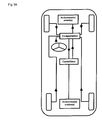
- the diagram in Figure 1 superimposes several methods: either we interpret the actions of the driver in demand for transverse thrusts which are compared to transverse thrusts measured at the wheel center, or we interpret the actions of the conductor in demand for load variations compared to loads measured at the wheel center, or we interpret the actions of the driver requesting yaw torque and transform the transverse thrust measurements at the wheel center in yaw torque measured to make the required comparison.
- the deviations revealed by a comparator allow a controller to decide the correction required by acting on the actuators to stabilize the vehicle and make it follow the instructions of the driver.
- an action on a means of additional steering imposed for example by means of a stepping motor irreversible inserted in the steering column, also allows to approach the resulting from efforts on the chassis in accordance with the driver's wishes.
- Another possibility of carrying out the action on a turning means consists for example in send the appropriate control orders to the controller described in the patent US 5,884,724.
- an action on the distribution of anti-roll between the front axle and the rear axle also makes it possible to act on the thrusts developed respectively by the front and rear axles. This amounts to modifying the load supported by each wheel by modifying the distribution between the wheels of the overall load (unchanged), all respecting the load transfer to the wheels outside the turn.
- the invention proposes, for a better determination of the corrective actions trajectory, to take account of the ground forces wheel by wheel.
- the comparing the thrust of each tire to the desired thrust allows know exactly the source of saturation of the entire axle and thus allows to choose more effective corrective actions.
- FIG. 3a a four-wheeled vehicle is shown diagrammatically, the center of which is seen gravity CG. Neither the angle ⁇ made by the speed vector with respect to the axis has been represented. longitudinal of the vehicle, nor the yaw angle ⁇ so as not to overload the figure.
- the quadricycle model is closer to the vehicle in the sense that it takes into account the efforts on the centers of the four wheels and that it expresses the load transfers lateral linked to the centrifugal force in turn.
- the quadricycle model is then more complete than the bicycle model and better reflects the action of the transfers of load on vehicle dynamics.
- the loads on each of the four tires are represented by Zp1, Zp2, Zp3, Zp4. Transverse thrusts (or lateral forces) appearing on each of the wheels indexed by the marks Yp1, Yp2, Yp3, Yp4.
- the diet stationary or the established regime.
- the speed of the steering wheel is rather considered equivalent to a desired yaw torque on the vehicle. If the actual torque is less than the desired torque, the vehicle does not turn enough. If this actual torque is greater than the desired torque, the vehicle turns too much.
- the controller then acts appropriately on one or the other or more of possible actuators such as the brakes or on a complementary steering means or on the anti-roll distribution makes it possible to obtain a yaw torque imposed on the chassis in accordance with the driver's wishes.
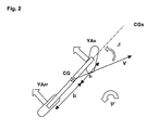
- the quantity 11 is the distance from the front axle (respectively rear) at the CG center of gravity of the vehicle. Vehicle geometry is presented in figure 2.
- Vc the critical speed
- V vs 2 D Av D Arr ( l 1 + l 2 ) 2 M
- D Arr l 2 - D Av l 1 D Av D Arr ( l 1 + l 2 )
- D Arr M Av - D Av M Arr l 1 + l 2 M
- formula (14) expresses the fact that the demand for yaw torque resulting from the driver's actions only depends on the control ( ⁇ c ) itself, on the speed of the vehicle (V) and on other parameters which are all functions of the vehicle itself (i.e. that describe the vehicle).
- the set point at time t depends on the steering control at time tT. This delay, related to the yawning inertia of the vehicle, appears as a characteristic time of the vehicle in equation (2a).
- T I Vehicle V l 2 1 D Av + l 2 2 D Arr
- transverse thrusts Y can be measured at any time for all the wheels, the variations of said thrusts Y, and the variations of angle at the steering wheel It is proposed to trigger a trajectory control system as soon as the gap between the desired effort and the actual effort measured is too large.
- the criterion of stability thus proposed expresses the fact that the vehicle remains stable as long as this difference is weak (adequacy between the driver's wish and reality).
- This stability criterion accounts for the fact that the thrust of the tire saturates either because the tire is no longer linear with the drift, or because the tire is no longer linear with the applied load. To better detect this double saturation, the assumption is made that the tire is linear with respect to the load and the drift.
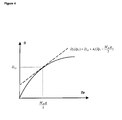
- This linearization is illustrated in FIG. 4. We see in solid line a real curve giving the value of the drift stiffness of a tire as a function of the load applied to the tire, and in broken line, the hypothesis adopted by the linearization , giving the value of the drift stiffness of a tire as a function of the load applied to the tire. We see that the deviation from reality increases when we approach the saturation (load) of the tire.
- the linear model representing the rigidity of the tire drift in relation to the load must give results comparable to reality near the operating point so as not to trigger a system in normal driving situations (see encounter zone continuous and broken lines).
- the proposed solution consists in modeling a theoretical tire which would have a linear drift stiffness (straight line in broken lines), tangent to a real drift stiffness curve at the static operating point M Av g / 2, i.e. without transfer dump.
- ⁇ D / ⁇ Z is the sensitivity of the drift rigidity to the transfer of charge in the vicinity of the static charge MAv g / 2. Note this sensitivity A1 at the front and A2 at the rear. D 1.0 is the drift stiffness of the front tire under static load MAv g / 2.
- the target load is then the sum of the static load on a quarter of vehicle and the load transfer on the axle.
- Zp 1 desired M Av g 2 + ⁇ Z Av longed for
- Zp 2 desired M Av g 2 - ⁇ Z Av longed for
- transverse thrusts Y can be measured at any time for all the wheels, the variations of said thrusts Y, and the variations of angle at the steering wheel It is proposed to trigger a trajectory control system as soon as the gap between the desired effort and the actual effort measured is too large.
- the criterion of stability thus proposed expresses the fact that the vehicle remains stable as long as this difference is weak (adequacy between the driver's wish and reality).
- a simulation of the dynamics of a vehicle in typical maneuvers is presented using the following figures.
- the simulation model used is a model quadricycle with 7 degrees of freedom, to translate the balance of the vehicle into yaw, pitch, roll, and rotate all four wheels.
- the four simulations presented illustrates a vehicle whose characteristics are those of a Golf, running at a speed of 90 km / h.
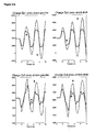
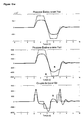
- the figure 6-a presents the thrusts of the front axle, the rear axle and the couple of actual and desired vehicle yaw.
- the figure 6-b represents the vertical loads Zp and desired on all four tires.
- the figure 6-c represents the pushes side Yp actual and desired on all four tires.
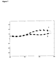
- Figure 7 symbolizes the vehicle (visualized by a rectangle) on the trajectory described by its center of gravity (illustrated by a continuous curve).
- the attitude of the vehicle is visible through the angle that the vehicle makes with the path.
- the phase difference between the actual attitude of the vehicle and the desired trajectory can be observed by noting, in some of the successive positions illustrated in the figure7, the greater or lesser angle between the orientation of the vehicle and the tangent to the trajectory at the center of gravity of the vehicle, until loss of control of the vehicle in oversteer.
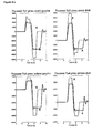
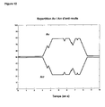
- Figure 8 illustrates the distribution of anti-roll to stabilize the vehicle
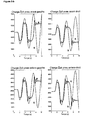
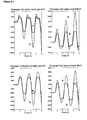
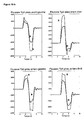
- FIG 9-a On the figure 9-a, one notes the saturation of the thrusts of the front and rear axles and the delay of thrust of the rear axle leading to the loss of control of the vehicle and to a swerve. This swerve is also illustrated by the overvoltage in the yaw torque compared to the yaw torque desired by the driver.
- the loss of control of the vehicle can be detected on a wheel-by-wheel basis by measuring the difference between the target thrusts (described by the formulas (25) (25 bis) (26) (26 bis) and the real thrusts or between the loads of instruction (described by the formulas (21) (21 bis), (22), (22 bis) and the real loads.
- Figure 9-b represents the vertical loads Zp real and desired on the four tires.
- the figure 9-c represents the real and desired lateral thrusts Yp on the 4 tires.
- the figure 10-a presents the thrusts of the front axle, the rear axle and the yaw torque of the vehicle, real and desired.
- the figure 10-b represents the vertical loads Zp, real and desired, on all four tires.
- the figure 10-c represents the lateral thrusts Yp, and desired, on all four tires.
Landscapes
- Engineering & Computer Science (AREA)
- Transportation (AREA)
- Mechanical Engineering (AREA)
- Steering Control In Accordance With Driving Conditions (AREA)
- Control Of Driving Devices And Active Controlling Of Vehicle (AREA)
- Vehicle Body Suspensions (AREA)
- Regulating Braking Force (AREA)
- Arrangement And Driving Of Transmission Devices (AREA)
Applications Claiming Priority (2)
| Application Number | Priority Date | Filing Date | Title |
|---|---|---|---|
| FR0113544A FR2830825A1 (fr) | 2001-10-17 | 2001-10-17 | Actions sur la trajectoire d'un vehicule a partir de la mesure des efforts transversaux, en tenant compte des transferts de charge de part et d'autre du plan median de symetrie du vehicule |
| FR0113544 | 2001-10-17 |
Publications (2)
| Publication Number | Publication Date |
|---|---|
| EP1304271A2 true EP1304271A2 (de) | 2003-04-23 |
| EP1304271A3 EP1304271A3 (de) | 2003-11-05 |
Family
ID=8868512
Family Applications (1)
| Application Number | Title | Priority Date | Filing Date |
|---|---|---|---|
| EP02022084A Withdrawn EP1304271A3 (de) | 2001-10-17 | 2002-10-02 | Fahrzeugsstabilitätsregelungsverfahren unter Verwendung von Reifenseitenkräften und unter Berücksichtigung der Seitenlastverlagerung |
Country Status (4)
| Country | Link |
|---|---|
| US (1) | US20030093207A1 (de) |
| EP (1) | EP1304271A3 (de) |
| JP (1) | JP2003231429A (de) |
| FR (1) | FR2830825A1 (de) |
Families Citing this family (15)
| Publication number | Priority date | Publication date | Assignee | Title |
|---|---|---|---|---|
| JP4282072B2 (ja) * | 2004-09-30 | 2009-06-17 | 本田技研工業株式会社 | 二輪車の運転者負荷測定方法、装置およびプログラムならびにその記憶媒体 |
| JP4515240B2 (ja) * | 2004-12-10 | 2010-07-28 | 本田技研工業株式会社 | 車両用懸架装置の制御装置 |
| US7774103B2 (en) * | 2005-07-28 | 2010-08-10 | Gm Global Technology Operations, Inc. | Online estimation of vehicle side-slip under linear operating region |
| US8565993B2 (en) * | 2005-10-11 | 2013-10-22 | Volvo Car Corporation | Enhanced yaw stability control to mitigate a vehicle's abnormal yaw motion due to a disturbance force applied to vehicle body |
| JP2007106218A (ja) * | 2005-10-12 | 2007-04-26 | Toyota Motor Corp | 車両の操舵制御装置 |
| GB2477341A (en) * | 2010-02-01 | 2011-08-03 | Gm Global Tech Operations Inc | A method of estimating a cornering limit of a vehicle |
| US9488267B2 (en) * | 2012-09-14 | 2016-11-08 | Ford Global Technologies, Llc | Line pressure control with input shaft torque measurement |
| TW201412585A (zh) * | 2012-09-18 | 2014-04-01 | Automotive Res & Testing Ct | 車輛彎道翻覆預防系統及其方法 |
| FR3028828B1 (fr) * | 2014-11-26 | 2016-12-23 | Jtekt Europe Sas | Detecteur de sous-virage et de survirage pour vehicule automobile |
| CN106347361B (zh) * | 2016-10-19 | 2018-12-11 | 长春工业大学 | 一种冗余驱动车辆动力学控制分配方法 |
| US11131076B2 (en) * | 2018-09-05 | 2021-09-28 | Deere & Company | Controlling a work machine based on in-rubber tire/track sensor |
| CN110209197B (zh) * | 2019-06-25 | 2022-03-25 | 湖北航天技术研究院总体设计所 | 一种飞行器控制系统设计方法 |
| US12283138B2 (en) | 2020-01-06 | 2025-04-22 | Deere & Company | Determination of applied loads on vehicle tracks by sensors on weight-bearing rollers |
| US11707983B2 (en) | 2020-01-30 | 2023-07-25 | Deere & Company | Sensing track characteristics on a track vehicle using replaceable track sensors |
| CN115435796B (zh) * | 2022-11-09 | 2023-03-21 | 苏州挚途科技有限公司 | 车辆的定位方法、装置和电子设备 |
Citations (6)
| Publication number | Priority date | Publication date | Assignee | Title |
|---|---|---|---|---|
| JPS60205037A (ja) | 1984-03-29 | 1985-10-16 | Bridgestone Corp | 弾性ブツシユ |
| DE3937966A1 (de) | 1989-11-15 | 1991-05-16 | Bert Prof Dr Ing Breuer | Verfahren und vorrichtung zur bestimmung der kraftschlussverhaeltnisse zwischen fahrzeugreifen und fahrbahn |
| US5502433A (en) | 1992-12-17 | 1996-03-26 | Continental Aktiengesellschaft | Method and device for detecting hydroplaning conditions for vehicle tires |
| EP0832807A2 (de) | 1996-09-27 | 1998-04-01 | Daimler-Benz Aktiengesellschaft | Verfahren zur Auswahl eines von mehreren gleichwirkenden Bedienelementen zur Steuerung der Längs- und/oder Querdynamik eines Fahrzeuges, insbesondere eines Kraftfahrzeuges |
| US5864056A (en) | 1998-02-17 | 1999-01-26 | Bell; Larry D. | Method and apparatus for monitoring the coefficient of friction between a tire and rolling surface, particularly to provide the vehicle operator with coefficient of friction, tire tread wear out and skid warning indications |
| US5884724A (en) | 1995-12-15 | 1999-03-23 | Mercedes-Benz Ag | Steering system for a non-track vehicle |
Family Cites Families (15)
| Publication number | Priority date | Publication date | Assignee | Title |
|---|---|---|---|---|
| US4761022A (en) * | 1986-03-08 | 1988-08-02 | Toyota Jidosha Kabushiki Kaisha | Suspension controller for improved turning |
| DE3821609A1 (de) * | 1988-06-27 | 1989-12-28 | Bayerische Motoren Werke Ag | Regelungseinrichtung zur wankstabilisierung eines fahrzeuges |
| DE3935588A1 (de) * | 1989-10-23 | 1991-04-25 | Forschungsgesellschaft Kraftfa | Verfahren zur gewaehrleistung der fahrstabilitaet von kraftfahrzeugen |
| FR2659920A1 (fr) * | 1990-03-22 | 1991-09-27 | Nissan Motor | Appareil de controle de la force de freinage d'un vehicule. |
| JP2583367B2 (ja) * | 1991-07-22 | 1997-02-19 | 日産自動車株式会社 | 制動力制御装置 |
| US5388658A (en) * | 1991-12-02 | 1995-02-14 | Imra America, Inc. | Integrated torque and steering control system |
| US5548536A (en) * | 1992-05-16 | 1996-08-20 | Daimler-Benz Ag | Method for determining quantities which characterize the driving behavior |
| DE4419131B4 (de) * | 1993-06-11 | 2008-12-18 | Volkswagen Ag | Kraftfahrzeug, vorzugweise Personenkraftfahrzeug |
| US6021367A (en) * | 1994-08-24 | 2000-02-01 | Ford Global Technologies, Inc. | Vehicle steering system and method for controlling vehicle direction through differential braking of left and right road wheels |
| JP3708989B2 (ja) * | 1995-05-16 | 2005-10-19 | 三菱自動車工業株式会社 | 車両の旋回制御装置 |
| DE19623595A1 (de) * | 1996-06-13 | 1997-12-18 | Teves Gmbh Alfred | Verfahren zur Regelung des Fahrverhaltens eines Fahrzeugs |
| US5852787A (en) * | 1996-09-03 | 1998-12-22 | Ford Global Technologies, Inc. | Vehicle suspension control |
| JPH10315945A (ja) * | 1997-05-20 | 1998-12-02 | Toyota Motor Corp | 車輌の安定走行制御装置 |
| WO2001019653A1 (de) * | 1999-09-10 | 2001-03-22 | Continental Teves Ag & Co. Ohg | Verfahren zur regelung eines giermoments |
| US6505108B2 (en) * | 2000-03-01 | 2003-01-07 | Delphi Technologies, Inc. | Damper based vehicle yaw control |
-
2001
- 2001-10-17 FR FR0113544A patent/FR2830825A1/fr active Pending
-
2002
- 2002-10-02 EP EP02022084A patent/EP1304271A3/de not_active Withdrawn
- 2002-10-16 JP JP2002301713A patent/JP2003231429A/ja not_active Withdrawn
- 2002-10-17 US US10/273,034 patent/US20030093207A1/en not_active Abandoned
Patent Citations (6)
| Publication number | Priority date | Publication date | Assignee | Title |
|---|---|---|---|---|
| JPS60205037A (ja) | 1984-03-29 | 1985-10-16 | Bridgestone Corp | 弾性ブツシユ |
| DE3937966A1 (de) | 1989-11-15 | 1991-05-16 | Bert Prof Dr Ing Breuer | Verfahren und vorrichtung zur bestimmung der kraftschlussverhaeltnisse zwischen fahrzeugreifen und fahrbahn |
| US5502433A (en) | 1992-12-17 | 1996-03-26 | Continental Aktiengesellschaft | Method and device for detecting hydroplaning conditions for vehicle tires |
| US5884724A (en) | 1995-12-15 | 1999-03-23 | Mercedes-Benz Ag | Steering system for a non-track vehicle |
| EP0832807A2 (de) | 1996-09-27 | 1998-04-01 | Daimler-Benz Aktiengesellschaft | Verfahren zur Auswahl eines von mehreren gleichwirkenden Bedienelementen zur Steuerung der Längs- und/oder Querdynamik eines Fahrzeuges, insbesondere eines Kraftfahrzeuges |
| US5864056A (en) | 1998-02-17 | 1999-01-26 | Bell; Larry D. | Method and apparatus for monitoring the coefficient of friction between a tire and rolling surface, particularly to provide the vehicle operator with coefficient of friction, tire tread wear out and skid warning indications |
Also Published As
| Publication number | Publication date |
|---|---|
| US20030093207A1 (en) | 2003-05-15 |
| JP2003231429A (ja) | 2003-08-19 |
| EP1304271A3 (de) | 2003-11-05 |
| FR2830825A1 (fr) | 2003-04-18 |
Similar Documents
| Publication | Publication Date | Title |
|---|---|---|
| EP1304270B1 (de) | Fahrzeugsstabilitätsregelungsverfahren unter Verwendung von Reifenseitenkräften, unter Berücksichtigung der Trägheit des Fahrzeugs | |
| EP3938260B1 (de) | Verfahren zur erzeugung eines sollwertes für die kombinierte regelung eines radlenksystems und eines differentialbremssystems eines kraftfahrzeuges | |
| EP1147960A1 (de) | Fahrzeugsstabilitätsregelungsverfahren unter Verwendung von Reifenseitenkräften | |
| EP4037947B1 (de) | Steuervorrichtung für ein selbstfahrendes kraftfahrzeug | |
| FR2830825A1 (fr) | Actions sur la trajectoire d'un vehicule a partir de la mesure des efforts transversaux, en tenant compte des transferts de charge de part et d'autre du plan median de symetrie du vehicule | |
| WO2021079004A1 (fr) | Procédé de commande d'un véhicule roulant en condition d'adhérence précaire | |
| EP4045385B1 (de) | Steuerung für seitliche unterstützung auf hohem niveau für 4hl-fahrzeuge | |
| WO2017037374A1 (fr) | Dispositif et procede de correction de trajectoire d'un vehicule automobile | |
| FR3055286A1 (fr) | Procede de stabilisation par amortissement d'un convoi de vehicules | |
| WO2018036723A1 (fr) | Procede de stabilisation par orientation d'un convoi de vehicules | |
| EP4168288B1 (de) | Steuerungssystem einer lenkvorrichtung in fahrzeugen | |
| CN119428837B (zh) | 一种车辆线控转向冗余控制方法 | |
| EP1907260B1 (de) | Verfahren zur steuerung der lenkausrichtung eines fahrzeugs | |
| EP2045112B1 (de) | System zur Regelung der Bodenhaftung eines Kraftfahrzeug-Antriebsradsatzes | |
| FR2915447A1 (fr) | Methode de modelisation d'un vehicule automobile | |
| FR2813576A1 (fr) | Procede de detection des pertes d'adherence d'un vehicule automobile et procede d'aide a la conduite associe | |
| EP2045166B1 (de) | Hilfskraftlenkvorrichtung eines Kraftfahrzeugs | |
| FR3092914A1 (fr) | Procédé de détermination de la trajectoire d'un véhicule comprenant quatre roues directrices | |
| FR2862265A1 (fr) | Procede de controle de la deceleration d'un vehicule a roues, utilisant des couples de freinage repartis a dissymetrie bornee | |
| EP1738991B1 (de) | System und Verfahren zur Ansteueren des Einschlagens der Hinterräder eines Fahrzeuges mit Vierradlenkung | |
| FR3143511A1 (fr) | Procédé et système de contrôle de trajectoire d’un véhicule | |
| WO2024104837A1 (fr) | Procédé de pilotage d'un véhicule automobile au centre de sa voie de circulation | |
| WO2021079003A1 (fr) | Procede de commande d'un vehicule roulant en condition d'adherence precaire | |
| FR2896753A1 (fr) | Procede et dispositif de compensation de variations de couple | |
| FR3055285A1 (fr) | Procede de stabilisation par entrainement d'un convoi de vehicules |
Legal Events
| Date | Code | Title | Description |
|---|---|---|---|
| PUAI | Public reference made under article 153(3) epc to a published international application that has entered the european phase |
Free format text: ORIGINAL CODE: 0009012 |
|
| AK | Designated contracting states |
Designated state(s): AT BE BG CH CY CZ DE DK EE ES FI FR GB GR IE IT LI LU MC NL PT SE SK TR |
|
| AX | Request for extension of the european patent |
Extension state: AL LT LV MK RO SI |
|
| PUAL | Search report despatched |
Free format text: ORIGINAL CODE: 0009013 |
|
| AK | Designated contracting states |
Kind code of ref document: A3 Designated state(s): AT BE BG CH CY CZ DE DK EE ES FI FR GB GR IE IT LI LU MC NL PT SE SK TR |
|
| AX | Request for extension of the european patent |
Extension state: AL LT LV MK RO SI |
|
| 17P | Request for examination filed |
Effective date: 20040506 |
|
| AKX | Designation fees paid |
Designated state(s): AT BE BG CH CY CZ DE DK EE ES FI FR GB GR IE IT LI LU MC NL PT SE SK TR |
|
| 17Q | First examination report despatched |
Effective date: 20040617 |
|
| STAA | Information on the status of an ep patent application or granted ep patent |
Free format text: STATUS: THE APPLICATION IS DEEMED TO BE WITHDRAWN |
|
| 18D | Application deemed to be withdrawn |
Effective date: 20060704 |