EP1304097B1 - Nasal irrigator - Google Patents
Nasal irrigator Download PDFInfo
- Publication number
- EP1304097B1 EP1304097B1 EP02023031A EP02023031A EP1304097B1 EP 1304097 B1 EP1304097 B1 EP 1304097B1 EP 02023031 A EP02023031 A EP 02023031A EP 02023031 A EP02023031 A EP 02023031A EP 1304097 B1 EP1304097 B1 EP 1304097B1
- Authority
- EP
- European Patent Office
- Prior art keywords
- valve body
- container
- douche
- douche according
- tube
- Prior art date
- Legal status (The legal status is an assumption and is not a legal conclusion. Google has not performed a legal analysis and makes no representation as to the accuracy of the status listed.)
- Expired - Lifetime
Links
Images


Classifications
-
- A—HUMAN NECESSITIES
- A61—MEDICAL OR VETERINARY SCIENCE; HYGIENE
- A61H—PHYSICAL THERAPY APPARATUS, e.g. DEVICES FOR LOCATING OR STIMULATING REFLEX POINTS IN THE BODY; ARTIFICIAL RESPIRATION; MASSAGE; BATHING DEVICES FOR SPECIAL THERAPEUTIC OR HYGIENIC PURPOSES OR SPECIFIC PARTS OF THE BODY
- A61H35/00—Baths for specific parts of the body
- A61H35/04—Baths for specific parts of the body for the nose
-
- A—HUMAN NECESSITIES
- A61—MEDICAL OR VETERINARY SCIENCE; HYGIENE
- A61M—DEVICES FOR INTRODUCING MEDIA INTO, OR ONTO, THE BODY; DEVICES FOR TRANSDUCING BODY MEDIA OR FOR TAKING MEDIA FROM THE BODY; DEVICES FOR PRODUCING OR ENDING SLEEP OR STUPOR
- A61M3/00—Medical syringes, e.g. enemata; Irrigators
- A61M3/02—Enemata; Irrigators
- A61M3/0233—Enemata; Irrigators characterised by liquid supply means, e.g. from pressurised reservoirs
- A61M3/0241—Enemata; Irrigators characterised by liquid supply means, e.g. from pressurised reservoirs the liquid being supplied by gravity
Definitions
- the invention relates to a nasal douche with a container for rinsing liquid, the one Having outlet, with a movably held in the region of the outlet opening Valve body with an attached thereto pipe, with different pivot positions the valve body in cooperation with the outlet opening an open position, in the the tube is connected to the container, and a closed position in which the container is closed, set, as it is known from DE 39 29 964 C2.
- the well-known nasal douche has proven itself in practice, but it is true has occasionally been found to be inconvenient in use, the shower after filling Always keep with rinsing liquid in your hand, otherwise the liquid expires. Furthermore, it could damage the pipe projecting from the container and / or come of the movable valve body.
- An object of the invention is therefore to the well-known nasal douche develop further that it is convenient to handle in use and damage the valve body or the tube attached thereto substantially excluded can be.
- Fig. 1 to 4 the structure and operation of the invention Show nasal shower.
- the nasal douche is in its upright or vertical position of use shown.
- a substantially cylindrical container 1 is with a removable cover 2, which has circumferential sealing lips 4, air and liquid-tight closed, the lid 2 a temporarily closed with a finger or to be released metering opening 6.
- the lid 2 by means of a circumferential clamping groove with a sealing and Halterungswulst the container cooperates, so that it does not dissolve then even from the container tightly closes when an internal pressure occurs in the container (pressurized dosing, see above).
- molded recessed grips 8 (Fig. 4) facilitate that Keep the shower and the simultaneous closing or opening of the metering 6th
- the container is closed inside about in its lower third with a bottom wall 10, the one recess 12 with a arranged in the lowermost portion of the recess outlet opening 14 forms.
- the side walls 16 of the container are over the area of the bottom wall Extended down 10 so that stands 18 for parking the container or the nasal douche are formed in the illustrated (vertical) position of use.
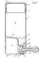
- a substantially cylindrical valve body 20 with an outgoing from this tube 22 is pivotally mounted adjacent to the outlet opening 14, so that in Fig. 1 to 3 shown different pivot positions can be taken.
- Fig. 1 shows the closed position of the valve body, in which the outlet opening 14 of the container is closed by a cylindrical outer surface 24 of the valve body 20.
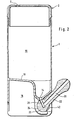
- Fig. 2 shows the use or open position, wherein a substantially radially in the Valve body 20 arranged connecting channel 26 with the outlet opening 14 in connection stands while a through the valve body and the tube 22 extending discharge channel Connects to the connecting channel 26, so that a located within the container Liquid can escape through the discharge channel 28.
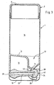
- Fig. 3 shows a ventilation position of the valve body 20 in which it pivots so far is. that the tube 22 connected thereto completely between the extended side walls 16 is and thus no longer on the cylindrical or approximately cuboid outer contour the container 1 survives, but is covered by this.
- connection channel 26 has rectangular cross-section and corresponds in shape and size in about the Outlet opening 14 (Fig. 7 and 8) or formed around it, with the sealing surface 24 cooperating bearing surface 25.
- valve body 20 At the bottom of the container are on the bottom wall 10 and the side walls 16 in essentially flat bearing tabs 32 formed in the lateral or axial direction (relative on the pivot axis of the valve body) flat boundary walls 34 and C-shaped, Having in the circumferential direction over more than 180 ° circumferential angle extending bearing webs 36.
- This configuration allows the valve body 20 to be elastically slightly elastic deformable bearing lugs 32 and the bearing webs 36 engaged and, in the opposite direction, can be removed, so that the valve body can be used non-destructive and is removable.
- the storage serving, lateral cylindrical end portions of the Valve body 20 and the bearing webs 36 (or the valve body in total) asymmetric be formed, e.g. left and right have different diameters, thus ensuring is that the valve body only in the correct orientation (and not rotated by 180 °) can be used.
- the hollow-cylindrical end sections or storage approaches are 21 of the valve body 20 is provided with locking lugs 38 in the closed position (Fig. 1) and Ventilation position (Fig. 3) with corresponding locking grooves 40 in the boundary walls 34th the bearing tabs 32 cooperate, so that the valve body 20 in said positions is held locked and an accidental pivoting in the open position is prevented.
- the locking lugs 38 and locking grooves 40 may alternatively be omitted be replaced or otherwise trained locking means.
- valve body 20 is an oblique, tangential flattening or residual emptying recess 42 in the ventilation position (Fig. 3) of the Dispensing opening 14 faces. This ensures that the container 1 in ventilation position at both ends, namely at the metering opening 6 on the one hand and the discharge opening 14 on the other hand, is open and is in communication with the ambient air, so that a Remaining emptying and ventilation is ensured.
- the nasal douche is placed in the closed position (FIG. 1), the lid 2 removed, filled a desired rinsing liquid and the lid put back on.
- the user takes the device in the vertical orientation shown in the drawing figures in one hand and closes, e.g. with the index finger, the dosage opening 6.
- the valve body completely or partially in the open position (Fig. 2), and the device is ready for use after fitting to the nose, with a dosage of Rinsing liquid by (partial) opening of the dosing opening 6 takes place, so that the rinsing liquid solely by gravity (hydrostatic pressure) exits the tube 22.
- the pressure may be achieved by closing the metering orifice 6 and squeezing of the container 1 (pressure on the side walls 16) are increased.
- valve body After use, the valve body is placed in the ventilation position (Fig. 3), whereby the discharge opening 14 is open due to the emptying recess 42 and possibly in the container 1 Residuals left on flushing liquid can escape freely.
- Located in the ventilation position all surfaces or channels of the device that come into contact with the rinsing fluid in connection with the environment, namely the container 1, the outlet opening 14, the discharge channel 28 and the connection opening 26th
- valve body 20 For the purpose of a thorough cleaning of the device, the valve body 20, as already mentioned, removed without damage from its storage and reinstated become. It is important that the sealing function (valve body opposite discharge opening) from the storage function (valve body to container) is structurally separated, so that too after repeated removal and replacement of the valve body, the sealing function is not affected.
- Another advantage is that the device on the footprints 18 at the bottom the side walls 16 in all positions of the valve body 20 (Fig. 1 to 3) can be turned off, in particular in closing and ventilation position, so that the handling is improved.
- the Possibility to bring the valve body in ventilation position has the advantage that the Tube 22 is protected from contamination and damage, with the residual emptying recess 42 at the same time for draining and ventilation.
Landscapes
- Health & Medical Sciences (AREA)
- Life Sciences & Earth Sciences (AREA)
- Veterinary Medicine (AREA)
- Public Health (AREA)
- General Health & Medical Sciences (AREA)
- Animal Behavior & Ethology (AREA)
- Hematology (AREA)
- Pain & Pain Management (AREA)
- Biomedical Technology (AREA)
- Anesthesiology (AREA)
- Engineering & Computer Science (AREA)
- Otolaryngology (AREA)
- Epidemiology (AREA)
- Heart & Thoracic Surgery (AREA)
- Physical Education & Sports Medicine (AREA)
- Rehabilitation Therapy (AREA)
- Infusion, Injection, And Reservoir Apparatuses (AREA)
- Devices For Medical Bathing And Washing (AREA)
- Closures For Containers (AREA)
- Medicines Containing Material From Animals Or Micro-Organisms (AREA)
- Medicinal Preparation (AREA)
- Containers And Packaging Bodies Having A Special Means To Remove Contents (AREA)
Abstract
Description
Die Erfindung betrifft eine Nasendusche mit einem Behälter für Spülflüssigkeit, der eine Austrittsöffnung aufweist, mit einem im Bereich der Austrittsöffnung beweglich gehaltenen Ventilkörper mit einem an diesem angesetzten Rohr, wobei unterschiedliche Schwenkpositionen des Ventilkörpers in Zusammenwirken mit der Austrittsöffnung eine Offenstellung, in der das Rohr mit dem Behälter verbunden ist, und eine Schließstellung, in der der Behälter verschlossen, festlegen, wie sie aus der DE 39 29 964 C2 bekannt ist.The invention relates to a nasal douche with a container for rinsing liquid, the one Having outlet, with a movably held in the region of the outlet opening Valve body with an attached thereto pipe, with different pivot positions the valve body in cooperation with the outlet opening an open position, in the the tube is connected to the container, and a closed position in which the container is closed, set, as it is known from DE 39 29 964 C2.
Die bekannte Nasendusche hat sich an sich in der Praxis bestens bewährt, wobei es sich allerdings im Gebrauch gelegentlich als unzweckmäßig herausgestellt hat, die Dusche nach Befüllung mit Spülflüssigkeit stets in der Hand halten zu müssen, da andernfalls die Flüssigkeit ausläuft. Ferner konnte es zu Beschädigungen des vom Behälter abstehenden Rohrs und/oder des beweglichen Ventilkörpers kommen.The well-known nasal douche has proven itself in practice, but it is true has occasionally been found to be inconvenient in use, the shower after filling Always keep with rinsing liquid in your hand, otherwise the liquid expires. Furthermore, it could damage the pipe projecting from the container and / or come of the movable valve body.
Eine Aufgabe der Erfindung besteht daher darin, die bekannte Nasendusche dahingehend weiterzuentwickeln, daß sie im Gebrauch zweckmäßiger handhabbar ist und eine Beschädigung des Ventilkörpers bzw. des daran angesetzten Rohrs im wesentlichen ausgeschlossen werden kann.An object of the invention is therefore to the well-known nasal douche develop further that it is convenient to handle in use and damage the valve body or the tube attached thereto substantially excluded can be.
Diese Aufgabe wird erfindungsgemäß durch eine Nasendusche nach Anspruch 1 gelöst. Zweckmäßige Weiterbildungen der Erfindung sind in den Unteransprüchen aufgezeigt.This object is achieved by a nasal douche according to claim 1. Advantageous developments of the invention are shown in the subclaims.
Die Erfindung wird nachfolgend anhand eines Ausführungsbeispiels erläutert, wobei auf eine
Zeichnung Bezug genommen ist, in der
Zunächst sei auf Fig. 1 bis 4 Bezug genommen, die Aufbau und Funktionsweise der erfindungsgemäßen
Nasendusche zeigen. Die Nasendusche ist in ihrer aufrecht stehenden bzw.
senkrechten Gebrauchsstellung dargestellt. Ein im wesentlichen zylindrischer Behälter 1 ist
mit einem abnehmbaren Deckel 2, der umlaufende Dichtlippen 4 aufweist, luft- und flüssigkeitsdicht
verschlossen, wobei der Deckel 2 eine mit einem Finger vorübergehend verschließbare
bzw. freizugebende Dosieröffnung 6 aufweist. Es kann vorgesehen sein, daß der Deckel
2 mittels einer umlaufenden Klemmnut mit einer Dicht- und Halterungswulst des Behälters
zusammenwirkt, so daß er sich auch dann nicht von dem Behälter löst bzw. auch dann noch
dicht schließt, wenn ein Innendruck in dem Behälter auftritt (Dosierung unter Druck, s.u.). An
äußeren Seitenwänden 16 des Behälters eingeformte Griffmulden 8 (Fig. 4) erleichtern das
Halten der Dusche und das gleichzeitige Verschließen bzw. Öffnen der Dosieröffnung 6.First, reference is made to Fig. 1 to 4, the structure and operation of the invention
Show nasal shower. The nasal douche is in its upright or
vertical position of use shown. A substantially cylindrical container 1 is
with a
Der Behälter ist innen etwa in seinem unteren Drittel mit einer Bodenwand 10 abgeschlossen,
die eine Vertiefung 12 mit einer im untersten Bereich der Vertiefung angeordneten Austrittsöffnung
14 bildet. Die Seitenwände 16 des Behälters sind über den Bereich der Bodenwand
10 hinweg nach unten verlängert, so daß Standflächen 18 zum Abstellen des Behälters
bzw. der Nasendusche in der dargestellten (vertikalen) Gebrauchsstellung gebildet werden.The container is closed inside about in its lower third with a
Ein im wesentlichen zylindrischer Ventilkörper 20 mit einem von diesem ausgehenden Rohr
22 ist benachbart zu der Austrittsöffnung 14 schwenkbar gelagert, so daß die in Fig. 1 bis 3
dargestellten unterschiedlichen Schwenkstellungen eingenommen werden können.A substantially
Fig. 1 zeigt die Schließstellung des Ventilkörpers, in der die Austrittsöffnung 14 des Behälters
durch eine zylindrische Außenfläche 24 des Ventilkörpers 20 verschlossen ist.Fig. 1 shows the closed position of the valve body, in which the outlet opening 14 of the container
is closed by a cylindrical
Fig. 2 zeigt die Benutzungs- oder Offenstellung, wobei eine im wesentlichen radial in dem
Ventilkörper 20 angeordneter Verbindungskanal 26 mit der Austrittsöffnung 14 in Verbindung
steht, während ein durch den Ventilkörper und das Rohr 22 verlaufender Abgabekanal
28an den Verbindungskanal 26 anschließt, so daß eine innerhalb des Behälters befindliche
Flüssigkeit durch den Abgabekanal 28 austreten kann.Fig. 2 shows the use or open position, wherein a substantially radially in the
Valve
Fig. 3 zeigt eine Belüftungsstellung des Ventilkörpers 20, in der dieser soweit verschwenkt
ist. daß das damit verbundene Rohr 22 vollständig zwischen den verlängerten Seitenwänden
16 liegt und somit nicht mehr über die zylindrische oder angenähert quaderförmige Außenkontur
des Behälters 1 übersteht, sondern von dieser abgedeckt ist.Fig. 3 shows a ventilation position of the
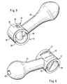
Fig. 5 und 6 zeigen vergrößerte Ansichten des Ventilkörpers 20 sowie des damit verbundenen
Rohrs 22, woraus die hohlzylindrische Grundform des Ventilkörpers ersichtlich ist. Der Verbindungskanal
26 hat rechteckigen Querschnitt und entspricht in Form und Größe in etwa der
Austrittsöffnung 14 (Fig. 7 und 8) bzw. der um diese herum ausgebildeten, mit der Dichtfläche
24 zusammenwirkenden Anlagefläche 25.5 and 6 show enlarged views of the
Am unteren Bereich des Behälters sind an der Bodenwand 10 und den Seitenwänden 16 im
wesentlichen ebene Lagerlappen 32 ausgebildet, die in seitlicher bzw. axialer Richtung (bezogen
auf die Schwenkachse des Ventilkörpers) ebene Begrenzungswände 34 sowie C-förmige,
in Umfangsrichtung über mehr als 180° Umfangswinkel verlaufende Lagerstege 36 aufweisen.
Diese Ausbildung ermöglicht es, daß der Ventilkörper 20 gegen die elastisch geringfügig
verformbaren Lagerlappen 32 bzw. die Lagerstege 36 eingerastet und, in umgekehrter Richtung,
herausgenommen werden kann, so daß der Ventilkörper zerstörungsfrei einsetzbar und
herausnehmbar ist.At the bottom of the container are on the
Alternativ könnten die der Lagerung dienenden, seitlichen zylindrischen Endabschnitte des
Ventilkörpers 20 sowie die Lagerstege 36 (bzw. der Ventilkörper insgesamt) asymmetrisch
ausgebildet sein, z.B. links und rechts unterschiedliche Durchmesser haben, damit sichergestellt
ist, daß der Ventilkörper nur in der korrekten Orientierung (und nicht um 180° verdreht)
eingesetzt werden kann.Alternatively, the storage serving, lateral cylindrical end portions of the
Valve
Wie Fig. 5 bis 7 ferner zeigen, sind die hohlzylindrischen Endabschnitte bzw. Lagerungsansätze
21 des Ventilkörpers 20 mit Rastnasen 38 versehen, die in Schließstellung (Fig. 1) und
Belüftungsstellung (Fig. 3) mit entsprechenden Rastnuten 40 in den Begrenzungswänden 34
der Lagerlappen 32 zusammenwirken, so daß der Ventilkörper 20 in den genannten Stellungen
arretiert gehalten wird und ein versehentliches Verschwenken in die Öffnungsstellung
verhindert wird. Die Rastnasen 38 und Rastnuten 40 können alternativ auch weggelassen
werden oder durch anders ausgebildete Rastmittel ersetzt werden.As also shown in FIGS. 5 to 7, the hollow-cylindrical end sections or storage approaches are
21 of the
Wie Fig. 3 und 6 weiter zeigen, ist der Ventilkörper 20 mit einer schrägen, tangentialen Abflachung
oder Restentleerungs-Aussparung 42 versehen, die in Belüftungsstellung (Fig. 3) der
Abgabeöffnung 14 gegenübersteht. Dadurch wird erreicht, daß der Behälter 1 in Belüftungsstellung
an beiden Enden, nämlich an der Dosierungsöffnung 6 einerseits und der Abgabeöffnung
14 andererseits, offen ist und mit der Umgebungsluft in Verbindung steht, so daß eine
Restentleerung und Belüftung sichergestellt ist. As further shown in FIGS. 3 and 6, the
Zum Gebrauch wird die Nasendusche in Verschlußstellung (Fig. 1) gebracht, der Deckel 2
abgenommen, eine gewünschte Spülflüssigkeit eingefüllt und der Deckel wieder aufgesetzt.
Der Benutzer nimmt das Gerät in der in den Zeichnungsfiguren dargestellten, vertikalen Orientierung
in eine Hand und verschließt, z.B. mit dem Zeigefinger, die Dosierungsöffnung 6.
Anschließend wird der Ventilkörper (ganz oder teilweise) in Öffnungsstellung (Fig. 2) gebracht,
und das Gerät ist nach Ansetzen an die Nase einsatzbereit, wobei eine Dosierung der
Spülflüssigkeit durch (teilweises) Öffnen der Dosierungsöffnung 6 erfolgt, so daß die Spülflüssigkeit
allein durch Schwerkraftwirkung (hydrostatischer Druck) aus dem Rohr 22 austritt.
Wenn gewünscht, kann der Druck durch Schließen der Dosierungsöffnung 6 und Zusammendrücken
des Behälters 1 (Druck auf die Seitenwände 16) erhöht werden.For use, the nasal douche is placed in the closed position (FIG. 1), the
Nach Gebrauch bringt man den Ventilkörper in Belüftungsstellung (Fig. 3), wodurch die Abgabeöffnung
14 aufgrund der Restentleerungs-Aussparung 42 offen ist und ggf. im Behälter 1
befindliche Reste an Spülflüssigkeit frei austreten können. In der Belüftungsstellung befinden
sich sämtliche mit Spülflüssigkeit in Berührung kommenden Flächen bzw. Kanäle des Geräts
in Verbindung mit der Umgebung, nämlich der Behälter 1, die Austrittsöffnung 14, der Abgabekanal
28 sowie die Verbindungsöffnung 26.After use, the valve body is placed in the ventilation position (Fig. 3), whereby the
Zum Zwecke einer gründlichen Reinigung des Geräts kann der Ventilkörper 20, wie bereits
erwähnt, beschädigungsfrei aus seiner Lagerung herausgenommen und wieder eingesetzt
werden. Wichtig ist hierbei, daß die Dichtfunktion (Ventilkörper gegenüber Abgabeöffnung)
von der Lagerungsfunktion (Ventilkörper an Behälter) konstruktiv getrennt ist, so daß auch
nach wiederholtem Herausnehmen und Wiedereinsetzen des Ventilkörpers die Dichtfunktion
nicht beeinträchtigt ist.For the purpose of a thorough cleaning of the device, the
Ein weiterer Vorteil besteht darin, daß das Gerät auf den Standflächen 18 am unteren Ende
der Seitenwände 16 in allen Stellungen des Ventilkörpers 20 (Fig. 1 bis 3) abstellbar ist, insbesondere
in Schließ- und Belüftungsstellung, so daß die Handhabung verbessert ist. Die
Möglichkeit, den Ventilkörper in Belüftungsstellung zu bringen, bietet den Vorteil, daß das
Rohr 22 vor Verunreinigungen und Beschädigungen geschützt ist, wobei die Restentleerungs-Aussparung
42 gleichzeitig für Entleerung und Belüftung sorgt. Another advantage is that the device on the
- 11
- Behältercontainer
- 22
- Deckelcover
- 44
- Dichtungslippesealing lip
- 66
- Dosierungsöffnungdosage opening
- 88th
- Griffmuldegrip
- 1010
- Bodenwandbottom wall
- 2323
- Vertiefungdeepening
- 1414
- Abgabeöffnungdischarge opening
- 1616
- SeitenwandSide wall
- 1818
- Standflächefootprint
- 2020
- Ventilkörpervalve body
- 2121
- Lagerungsansatzstorage approach
- 2222
- Rohrpipe
- 2424
- Außenfläche (Dichtfläche)Outer surface (sealing surface)
- 2525
- Anlageflächecontact surface
- 2626
- Verbindungskanalconnecting channel
- 2828
- Abgabekanaldelivery channel
- 3232
- Lagerlappenbearing tabs
- 3434
- Begrenzungswandboundary wall
- 3636
- Lagerungsstegstorage Steg
- 3838
- Rastnaselocking lug
- 4040
- Rastnutlocking groove
- 4242
- Restentleerungs-AussparungRest flush recess
Claims (18)
- A nasal douche, comprising a container (1) for rinsing liquid, said container having an exit opening (14), a valve body (20) held movably in the region of the exit opening (4) and having a tube (22) attached to said valve body, wherein different pivoted positions of the valve body (20) in conjunction with the exit opening (14) fix an open position (Fig. 2) in which the tube (22) is connected to the container (1), and a closed position (Fig. 1), in which the container (1) is closed, characterised in that the valve body (20) is pivotable into an aerating position (Fig. 3) which differs from the open and closed positions and in which the container can be completely emptied and aerated.
- A douche according to claim 1, characterised in that the container has an outer contour which engages over or covers the valve body (20) and tube (22) in the aerating position, the said outer contour being formed with support surfaces (18) on which the douche can be set down.
- A douche according to claim 1 or 2, characterised in that the valve body (20) comprises a complete emptying opening (42) which in the aerating position communicates with the exit opening (14).
- A douche according to any one of claims 1 to 3, characterised in that the valve body (20) has a curved sealing surface (24) which co-operates with the exit opening (14) in the open and closed positions, while in the open position a connecting duct (26) connected to the tube (22) and leading into the sealing surface (24) communicates with the exit opening (14).
- A douche according to claim 4, characterised in that the outside of the container has an abutment surface (25) curved to correspond to the sealing surface (24) in the region of the dispensing opening (14).
- A douche according to any one of the preceding claims, characterised in that the valve body (20) has associated detent elements (38) which in at least one position, particularly the closed and/or aerating position, co-operate with corresponding detent elements (40) of the container and secure the valve body (20) against unintentional pivoting.
- A douche according to any one of the preceding claims, characterised in that the valve body (20) can be transferred from the closed position to the open position by pivoting through about 30° to about 60°, particularly about 45°.
- A douche according to any one of the preceding claims, characterised in that the valve body (20) is of cylindrical construction and its end portions are provided with bearing attachments (21).
- A douche according to any one of the preceding claims, characterised in that the valve body (20) has cylindrical bearing attachments (21) to be received in corresponding bearing recesses (34, 36) of the container (1).
- A douche according to claim 9, characterised in that the bearing attachments (21) and bearing recesses (34, 36) are of asymmetrical construction.
- A douche according to any one of claims 8 to 10, characterised in that the complete emptying opening (42) is formed as a flattening of the cylindrical valve body (20).
- A douche according to any one of the preceding claims, characterised in that the valve body can be removed from and re-inserted in the container non-destructively.
- A douche according to any one of the preceding claims, characterised in that the valve body (20) is mounted in lateral bearing lugs (32) of the container (1) which have C-shaped bearing webs (36) extending over a peripheral angle of more than 180°.
- A douche according to claim 13, characterised in that the bearing lugs (32) are formed on side walls (16) of the container, between which the valve body (20) and tube (22) can be received in the aerating position.
- A douche according to any one of the preceding claims, characterised in that the support surfaces (8) are formed by free end portions of side walls (16) of the container (1).
- A douche according to any one of the preceding claims, characterised in that the tube (22) is formed in one piece with the valve body (20) or is constructed to be pushed on to the latter.
- A douche according to any one of the preceding claims, characterised in that the container (1) is provided with a sealing lid (2) having a dispensing opening (6).
- A douche according to claim 17, characterised in that the lid (2) is so held on the container (1) that it seals even in the event of internal pressure.
Applications Claiming Priority (2)
| Application Number | Priority Date | Filing Date | Title |
|---|---|---|---|
| DE10151676A DE10151676A1 (en) | 2001-10-19 | 2001-10-19 | nasal douche |
| DE10151676 | 2001-10-19 |
Publications (2)
| Publication Number | Publication Date |
|---|---|
| EP1304097A1 EP1304097A1 (en) | 2003-04-23 |
| EP1304097B1 true EP1304097B1 (en) | 2004-09-15 |
Family
ID=7703063
Family Applications (1)
| Application Number | Title | Priority Date | Filing Date |
|---|---|---|---|
| EP02023031A Expired - Lifetime EP1304097B1 (en) | 2001-10-19 | 2002-10-16 | Nasal irrigator |
Country Status (10)
| Country | Link |
|---|---|
| US (1) | US7165549B2 (en) |
| EP (1) | EP1304097B1 (en) |
| JP (1) | JP4266824B2 (en) |
| AT (1) | ATE275913T1 (en) |
| AU (1) | AU2002339370B2 (en) |
| CA (1) | CA2464032C (en) |
| DE (2) | DE10151676A1 (en) |
| EG (1) | EG23348A (en) |
| TW (1) | TW568782B (en) |
| WO (1) | WO2003034973A1 (en) |
Families Citing this family (12)
| Publication number | Priority date | Publication date | Assignee | Title |
|---|---|---|---|---|
| US7204246B1 (en) * | 2004-07-08 | 2007-04-17 | Joseph Berinato | Air self-contained oxygen inhaler |
| DE102005035130A1 (en) * | 2005-07-26 | 2007-02-01 | Siemens & Co. Heilwasser Und Quellenprodukte Des Staatsbades Bad Ems Gmbh & Co. Kg | nasal douche |
| JP5164840B2 (en) | 2005-08-02 | 2013-03-21 | ソル − ゲル テクノロジーズ リミテッド | Metal oxide coating for water-insoluble components |
| US20070296210A1 (en) * | 2006-06-23 | 2007-12-27 | World Friendship Co., Ltd. | Universal joint |
| DE202007012817U1 (en) * | 2007-09-13 | 2007-12-20 | Siemens & Co. Heilwasser Und Quellenprodukte Des Staatsbades Bad Ems Gmbh & Co. Kg | Check valve for a nasal douche |
| US10549289B2 (en) * | 2008-06-18 | 2020-02-04 | Silgan Dispensing Systems Slatersville, Llc | Fan orifice dispensing closure |
| US9687465B2 (en) | 2012-11-27 | 2017-06-27 | Sol-Gel Technologies Ltd. | Compositions for the treatment of rosacea |
| CA2892398C (en) | 2012-12-04 | 2023-02-14 | Ino Therapeutics Llc | Cannula for minimizing dilution of dosing during nitric oxide delivery |
| US9795756B2 (en) | 2012-12-04 | 2017-10-24 | Mallinckrodt Hospital Products IP Limited | Cannula for minimizing dilution of dosing during nitric oxide delivery |
| EP2868334B1 (en) * | 2013-11-05 | 2017-01-11 | Benedict Gerber | Nasal spray |
| PT109030B (en) | 2015-12-15 | 2019-09-25 | Hovione Farmaciência, S.A. | PREPARATION OF ZAFIRLUCAST INHALABLE PARTICULES |
| US11358760B2 (en) * | 2019-09-10 | 2022-06-14 | Helen Of Troy Limited | Straw lid assembly |
Family Cites Families (15)
| Publication number | Priority date | Publication date | Assignee | Title |
|---|---|---|---|---|
| GB757679A (en) * | 1954-10-21 | 1956-09-19 | Harry Albert Mart | Improved liquid container dispensing device |
| US3089626A (en) * | 1960-05-25 | 1963-05-14 | Polytop Corp | Pouring spout construction |
| US3542256A (en) * | 1968-09-16 | 1970-11-24 | Atlantic Design & Dev Corp | Liquid container dispensing closures |
| US3812853A (en) * | 1971-11-17 | 1974-05-28 | P Crain | Apparatus for applying medication or the like to human nasal passages |
| US3847145A (en) * | 1973-04-13 | 1974-11-12 | M Grossan | Nasal irrigation system |
| DE3332723A1 (en) * | 1983-09-10 | 1985-03-28 | Michael 6430 Bad Hersfeld Post | Stomach irrigation apparatus |
| AT396747B (en) * | 1989-07-26 | 1993-11-25 | Pechatschek Hans | EQUIPMENT FOR NOSE OR EARWASHING |
| IT1266794B1 (en) * | 1993-11-09 | 1997-01-21 | Faustino Ballini | MICRONIZED SHOWER DEVICE FOR WASHING THE NASAL AND NEIGHBORING CAVITIES |
| JPH1017039A (en) * | 1996-07-02 | 1998-01-20 | Kanebo Ltd | Nasal lavage container |
| US6238377B1 (en) * | 1997-01-27 | 2001-05-29 | Jin-Zhou Liu | Nasal-nasopharyngeal cleaning system |
| DE19831525A1 (en) * | 1998-07-14 | 2000-01-20 | Pfeiffer Erich Gmbh & Co Kg | Media Donor |
| GB0121568D0 (en) * | 2001-09-06 | 2001-10-24 | Optinose As | Nasal delivery device |
| FR2823730B1 (en) * | 2001-04-24 | 2003-12-12 | Valois Sa | FLUID PRODUCT DISPENSING DEVICE |
| US6793104B2 (en) * | 2001-12-17 | 2004-09-21 | I-Feng Kao | Cork device for resealing a bottle |
| BR0300664B1 (en) * | 2003-03-06 | 2012-08-07 | breather for liquid packaging. |
-
2001
- 2001-10-19 DE DE10151676A patent/DE10151676A1/en not_active Withdrawn
-
2002
- 2002-10-16 US US10/493,003 patent/US7165549B2/en not_active Expired - Lifetime
- 2002-10-16 EP EP02023031A patent/EP1304097B1/en not_active Expired - Lifetime
- 2002-10-16 DE DE50201000T patent/DE50201000D1/en not_active Expired - Lifetime
- 2002-10-16 AU AU2002339370A patent/AU2002339370B2/en not_active Expired
- 2002-10-16 CA CA002464032A patent/CA2464032C/en not_active Expired - Lifetime
- 2002-10-16 AT AT02023031T patent/ATE275913T1/en active
- 2002-10-16 JP JP2003537542A patent/JP4266824B2/en not_active Expired - Lifetime
- 2002-10-16 WO PCT/DE2002/003913 patent/WO2003034973A1/en active IP Right Grant
- 2002-10-18 TW TW091124026A patent/TW568782B/en not_active IP Right Cessation
- 2002-10-19 EG EG2002101148A patent/EG23348A/en active
Also Published As
| Publication number | Publication date |
|---|---|
| DE10151676A1 (en) | 2003-05-08 |
| US20050045181A1 (en) | 2005-03-03 |
| ATE275913T1 (en) | 2004-10-15 |
| CA2464032C (en) | 2008-02-12 |
| EG23348A (en) | 2005-01-31 |
| DE50201000D1 (en) | 2004-10-21 |
| AU2002339370B2 (en) | 2007-07-19 |
| WO2003034973A1 (en) | 2003-05-01 |
| JP4266824B2 (en) | 2009-05-20 |
| JP2005506150A (en) | 2005-03-03 |
| US7165549B2 (en) | 2007-01-23 |
| CA2464032A1 (en) | 2003-05-01 |
| TW568782B (en) | 2004-01-01 |
| EP1304097A1 (en) | 2003-04-23 |
Similar Documents
| Publication | Publication Date | Title |
|---|---|---|
| EP1304097B1 (en) | Nasal irrigator | |
| DE2642174C2 (en) | DEVICE FOR DELIVERING A AEROSOL | |
| EP0140919B1 (en) | Spraying device, particularly brush-like apparatus for the cleaning and/or massage of the body, for example tooth-brush | |
| DE69925620T2 (en) | DISPENSER IN THE FORM OF A COVER | |
| EP2134475A1 (en) | Device for spraying pigmented fluids | |
| DE3124441A1 (en) | PUMP FOR FLUID RESERVOIR | |
| EP0738668A1 (en) | Aerosol actuator with hand-grip | |
| DE20321260U1 (en) | Alcoholic beverage dispensing apparatus for dispensing e.g. wine, beer from bag within container, includes dispensing adaptor mounted to valve assembly and coupled to tap operable between open and close position | |
| DE102018002101A1 (en) | Dispensing store and dispenser | |
| EP2846927B1 (en) | Wearable spraying device | |
| EP0064949A1 (en) | Container closure for a tapping unit | |
| EP1180343B1 (en) | Cleaning device | |
| DE3525194C2 (en) | ||
| DE3929964C2 (en) | Nasal and ear showers | |
| EP2295372A1 (en) | Pressure cap for beer containers and method for operating same | |
| DE1550099A1 (en) | Distribution valve | |
| WO2017207637A2 (en) | Device for filling tanks, comprising an intermediate container | |
| EP1403206B1 (en) | Tap | |
| DE4202592A1 (en) | Dispenser for bottle or flask - has adaptor with safety closure element for suction channel | |
| DE9415691U1 (en) | Pressure sprayer, such as hand-held fire extinguishers, crop protection sprayers or the like. | |
| DE2524624B2 (en) | Liquid dispensers, in particular for liquid soap | |
| DE19617417A1 (en) | Manual spray gun for a high pressure cleaning device | |
| WO2017008782A1 (en) | Hygiene shower | |
| DE8603167U1 (en) | Pouring device for containers | |
| DE8303136U1 (en) | DEVICE FOR TARGETED ORDERING OR SPRAYING ON LIQUID COSMETIC PREPARATIONS |
Legal Events
| Date | Code | Title | Description |
|---|---|---|---|
| PUAI | Public reference made under article 153(3) epc to a published international application that has entered the european phase |
Free format text: ORIGINAL CODE: 0009012 |
|
| AK | Designated contracting states |
Designated state(s): AT BE BG CH CY CZ DE DK EE ES FI FR GB GR IE IT LI LU MC NL PT SE SK TR |
|
| AX | Request for extension of the european patent |
Extension state: AL LT LV MK RO SI |
|
| 17P | Request for examination filed |
Effective date: 20030827 |
|
| 17Q | First examination report despatched |
Effective date: 20031118 |
|
| AKX | Designation fees paid |
Designated state(s): AT BE BG CH CY CZ DE DK EE ES FI FR GB GR IE IT LI LU MC NL PT SE SK TR |
|
| GRAP | Despatch of communication of intention to grant a patent |
Free format text: ORIGINAL CODE: EPIDOSNIGR1 |
|
| RAP1 | Party data changed (applicant data changed or rights of an application transferred) |
Owner name: HEXAL AG |
|
| GRAS | Grant fee paid |
Free format text: ORIGINAL CODE: EPIDOSNIGR3 |
|
| GRAA | (expected) grant |
Free format text: ORIGINAL CODE: 0009210 |
|
| AK | Designated contracting states |
Kind code of ref document: B1 Designated state(s): AT BE BG CH CY CZ DE DK EE ES FI FR GB GR IE IT LI LU MC NL PT SE SK TR |
|
| PG25 | Lapsed in a contracting state [announced via postgrant information from national office to epo] |
Ref country code: IT Free format text: LAPSE BECAUSE OF FAILURE TO SUBMIT A TRANSLATION OF THE DESCRIPTION OR TO PAY THE FEE WITHIN THE PRESCRIBED TIME-LIMIT;WARNING: LAPSES OF ITALIAN PATENTS WITH EFFECTIVE DATE BEFORE 2007 MAY HAVE OCCURRED AT ANY TIME BEFORE 2007. THE CORRECT EFFECTIVE DATE MAY BE DIFFERENT FROM THE ONE RECORDED. Effective date: 20040915 Ref country code: FI Free format text: LAPSE BECAUSE OF FAILURE TO SUBMIT A TRANSLATION OF THE DESCRIPTION OR TO PAY THE FEE WITHIN THE PRESCRIBED TIME-LIMIT Effective date: 20040915 Ref country code: TR Free format text: LAPSE BECAUSE OF FAILURE TO SUBMIT A TRANSLATION OF THE DESCRIPTION OR TO PAY THE FEE WITHIN THE PRESCRIBED TIME-LIMIT Effective date: 20040915 Ref country code: BG Free format text: LAPSE BECAUSE OF FAILURE TO SUBMIT A TRANSLATION OF THE DESCRIPTION OR TO PAY THE FEE WITHIN THE PRESCRIBED TIME-LIMIT Effective date: 20040915 Ref country code: NL Free format text: LAPSE BECAUSE OF FAILURE TO SUBMIT A TRANSLATION OF THE DESCRIPTION OR TO PAY THE FEE WITHIN THE PRESCRIBED TIME-LIMIT Effective date: 20040915 Ref country code: IE Free format text: LAPSE BECAUSE OF FAILURE TO SUBMIT A TRANSLATION OF THE DESCRIPTION OR TO PAY THE FEE WITHIN THE PRESCRIBED TIME-LIMIT Effective date: 20040915 Ref country code: CZ Free format text: LAPSE BECAUSE OF FAILURE TO SUBMIT A TRANSLATION OF THE DESCRIPTION OR TO PAY THE FEE WITHIN THE PRESCRIBED TIME-LIMIT Effective date: 20040915 Ref country code: CY Free format text: LAPSE BECAUSE OF FAILURE TO SUBMIT A TRANSLATION OF THE DESCRIPTION OR TO PAY THE FEE WITHIN THE PRESCRIBED TIME-LIMIT Effective date: 20040915 Ref country code: EE Free format text: LAPSE BECAUSE OF FAILURE TO SUBMIT A TRANSLATION OF THE DESCRIPTION OR TO PAY THE FEE WITHIN THE PRESCRIBED TIME-LIMIT Effective date: 20040915 Ref country code: SK Free format text: LAPSE BECAUSE OF FAILURE TO SUBMIT A TRANSLATION OF THE DESCRIPTION OR TO PAY THE FEE WITHIN THE PRESCRIBED TIME-LIMIT Effective date: 20040915 |
|
| REG | Reference to a national code |
Ref country code: GB Ref legal event code: FG4D Free format text: NOT ENGLISH Ref country code: CH Ref legal event code: EP |
|
| PG25 | Lapsed in a contracting state [announced via postgrant information from national office to epo] |
Ref country code: LU Free format text: LAPSE BECAUSE OF NON-PAYMENT OF DUE FEES Effective date: 20041016 |
|
| REG | Reference to a national code |
Ref country code: IE Ref legal event code: FG4D Free format text: GERMAN |
|
| REF | Corresponds to: |
Ref document number: 50201000 Country of ref document: DE Date of ref document: 20041021 Kind code of ref document: P |
|
| PG25 | Lapsed in a contracting state [announced via postgrant information from national office to epo] |
Ref country code: MC Free format text: LAPSE BECAUSE OF NON-PAYMENT OF DUE FEES Effective date: 20041031 Ref country code: BE Free format text: LAPSE BECAUSE OF NON-PAYMENT OF DUE FEES Effective date: 20041031 |
|
| REG | Reference to a national code |
Ref country code: CH Ref legal event code: NV Representative=s name: NOVAGRAAF INTERNATIONAL SA |
|
| PG25 | Lapsed in a contracting state [announced via postgrant information from national office to epo] |
Ref country code: GR Free format text: LAPSE BECAUSE OF FAILURE TO SUBMIT A TRANSLATION OF THE DESCRIPTION OR TO PAY THE FEE WITHIN THE PRESCRIBED TIME-LIMIT Effective date: 20041215 Ref country code: DK Free format text: LAPSE BECAUSE OF FAILURE TO SUBMIT A TRANSLATION OF THE DESCRIPTION OR TO PAY THE FEE WITHIN THE PRESCRIBED TIME-LIMIT Effective date: 20041215 Ref country code: SE Free format text: LAPSE BECAUSE OF FAILURE TO SUBMIT A TRANSLATION OF THE DESCRIPTION OR TO PAY THE FEE WITHIN THE PRESCRIBED TIME-LIMIT Effective date: 20041215 |
|
| PG25 | Lapsed in a contracting state [announced via postgrant information from national office to epo] |
Ref country code: ES Free format text: LAPSE BECAUSE OF FAILURE TO SUBMIT A TRANSLATION OF THE DESCRIPTION OR TO PAY THE FEE WITHIN THE PRESCRIBED TIME-LIMIT Effective date: 20041226 |
|
| NLV1 | Nl: lapsed or annulled due to failure to fulfill the requirements of art. 29p and 29m of the patents act | ||
| REG | Reference to a national code |
Ref country code: IE Ref legal event code: FD4D |
|
| BERE | Be: lapsed |
Owner name: HEXAL A.G. Effective date: 20041031 |
|
| ET | Fr: translation filed | ||
| RAP2 | Party data changed (patent owner data changed or rights of a patent transferred) |
Owner name: SIEMENS & CO. HEILWASSER UND QUELLENPRODUKTE D |
|
| PLBE | No opposition filed within time limit |
Free format text: ORIGINAL CODE: 0009261 |
|
| STAA | Information on the status of an ep patent application or granted ep patent |
Free format text: STATUS: NO OPPOSITION FILED WITHIN TIME LIMIT |
|
| REG | Reference to a national code |
Ref country code: CH Ref legal event code: PUE Owner name: SIEMENS & CO. HEILWASSER UND QUELLENPRODUKTE DES Free format text: HEXAL AG#INDUSTRIESTRASSE 25#83607 HOLZKIRCHEN (DE) -TRANSFER TO- SIEMENS & CO. HEILWASSER UND QUELLENPRODUKTE DES STAATSBADES BAD EMS & CO. KG#ARZBACHER STRASSE 78#56130 BAD EMS (DE) |
|
| 26N | No opposition filed |
Effective date: 20050616 |
|
| REG | Reference to a national code |
Ref country code: GB Ref legal event code: 732E |
|
| REG | Reference to a national code |
Ref country code: FR Ref legal event code: TP |
|
| BERE | Be: lapsed |
Owner name: *HEXAL A.G. Effective date: 20041031 |
|
| PG25 | Lapsed in a contracting state [announced via postgrant information from national office to epo] |
Ref country code: PT Free format text: LAPSE BECAUSE OF NON-PAYMENT OF DUE FEES Effective date: 20050215 |
|
| REG | Reference to a national code |
Ref country code: FR Ref legal event code: PLFP Year of fee payment: 15 |
|
| REG | Reference to a national code |
Ref country code: FR Ref legal event code: PLFP Year of fee payment: 16 |
|
| REG | Reference to a national code |
Ref country code: FR Ref legal event code: PLFP Year of fee payment: 17 |
|
| REG | Reference to a national code |
Ref country code: DE Ref legal event code: R082 Ref document number: 50201000 Country of ref document: DE Representative=s name: BOEHMERT & BOEHMERT ANWALTSPARTNERSCHAFT MBB -, DE Ref country code: DE Ref legal event code: R081 Ref document number: 50201000 Country of ref document: DE Owner name: SIDROGA GESELLSCHAFT FUER GESUNDHEITSPRODUKTE , DE Free format text: FORMER OWNER: SIEMENS & CO. HEILWASSER UND QUELLENPRODUKTE DES STAATSBADES BAD EMS GMBH & CO KG, 56130 BAD EMS, DE |
|
| REG | Reference to a national code |
Ref country code: CH Ref legal event code: PUE Owner name: SIDROGA GESELLSCHAFT FUER GESUNDHEITSPRODUKTE , DE Free format text: FORMER OWNER: SIEMENS AND CO. HEILWASSER UND QUELLENPRODUKTE DES STAATSBADES BAD EMS AND CO. KG, DE |
|
| REG | Reference to a national code |
Ref country code: GB Ref legal event code: 732E Free format text: REGISTERED BETWEEN 20210218 AND 20210224 |
|
| REG | Reference to a national code |
Ref country code: AT Ref legal event code: PC Ref document number: 275913 Country of ref document: AT Kind code of ref document: T Owner name: SIDROGA GESELLSCHAFT FUER GESUNDHEITSPRODUKTE M, DE Effective date: 20210323 |
|
| PGFP | Annual fee paid to national office [announced via postgrant information from national office to epo] |
Ref country code: FR Payment date: 20210913 Year of fee payment: 20 Ref country code: CH Payment date: 20210928 Year of fee payment: 20 |
|
| PGFP | Annual fee paid to national office [announced via postgrant information from national office to epo] |
Ref country code: GB Payment date: 20210907 Year of fee payment: 20 |
|
| PGFP | Annual fee paid to national office [announced via postgrant information from national office to epo] |
Ref country code: AT Payment date: 20210928 Year of fee payment: 20 Ref country code: DE Payment date: 20211101 Year of fee payment: 20 |
|
| REG | Reference to a national code |
Ref country code: DE Ref legal event code: R071 Ref document number: 50201000 Country of ref document: DE |
|
| REG | Reference to a national code |
Ref country code: CH Ref legal event code: PL |
|
| REG | Reference to a national code |
Ref country code: GB Ref legal event code: PE20 Expiry date: 20221015 |
|
| REG | Reference to a national code |
Ref country code: AT Ref legal event code: MK07 Ref document number: 275913 Country of ref document: AT Kind code of ref document: T Effective date: 20221016 |
|
| PG25 | Lapsed in a contracting state [announced via postgrant information from national office to epo] |
Ref country code: GB Free format text: LAPSE BECAUSE OF EXPIRATION OF PROTECTION Effective date: 20221015 |