EP1303122A2 - Verfahren zum Ansteuern eines Anzeigeelementes an einem Endgerät und zugehörige Einheiten - Google Patents
Verfahren zum Ansteuern eines Anzeigeelementes an einem Endgerät und zugehörige Einheiten Download PDFInfo
- Publication number
- EP1303122A2 EP1303122A2 EP02102419A EP02102419A EP1303122A2 EP 1303122 A2 EP1303122 A2 EP 1303122A2 EP 02102419 A EP02102419 A EP 02102419A EP 02102419 A EP02102419 A EP 02102419A EP 1303122 A2 EP1303122 A2 EP 1303122A2
- Authority
- EP
- European Patent Office
- Prior art keywords
- display element
- terminal
- message
- call
- csta
- Prior art date
- Legal status (The legal status is an assumption and is not a legal conclusion. Google has not performed a legal analysis and makes no representation as to the accuracy of the status listed.)
- Granted
Links
Images


Classifications
-
- H—ELECTRICITY
- H04—ELECTRIC COMMUNICATION TECHNIQUE
- H04M—TELEPHONIC COMMUNICATION
- H04M3/00—Automatic or semi-automatic exchanges
- H04M3/42—Systems providing special services or facilities to subscribers
- H04M3/42212—Call pickup
-
- H—ELECTRICITY
- H04—ELECTRIC COMMUNICATION TECHNIQUE
- H04M—TELEPHONIC COMMUNICATION
- H04M19/00—Current supply arrangements for telephone systems
- H04M19/02—Current supply arrangements for telephone systems providing ringing current or supervisory tones, e.g. dialling tone or busy tone
- H04M19/04—Current supply arrangements for telephone systems providing ringing current or supervisory tones, e.g. dialling tone or busy tone the ringing-current being generated at the substations
-
- H—ELECTRICITY
- H04—ELECTRIC COMMUNICATION TECHNIQUE
- H04M—TELEPHONIC COMMUNICATION
- H04M3/00—Automatic or semi-automatic exchanges
- H04M3/42—Systems providing special services or facilities to subscribers
- H04M3/42314—Systems providing special services or facilities to subscribers in private branch exchanges
- H04M3/42323—PBX's with CTI arrangements
-
- H—ELECTRICITY
- H04—ELECTRIC COMMUNICATION TECHNIQUE
- H04M—TELEPHONIC COMMUNICATION
- H04M7/00—Arrangements for interconnection between switching centres
- H04M7/009—Arrangements for interconnection between switching centres in systems involving PBX or KTS networks
-
- H—ELECTRICITY
- H04—ELECTRIC COMMUNICATION TECHNIQUE
- H04M—TELEPHONIC COMMUNICATION
- H04M2203/00—Aspects of automatic or semi-automatic exchanges
- H04M2203/20—Aspects of automatic or semi-automatic exchanges related to features of supplementary services
- H04M2203/2044—Group features, e.g. closed user group
-
- H—ELECTRICITY
- H04—ELECTRIC COMMUNICATION TECHNIQUE
- H04M—TELEPHONIC COMMUNICATION
- H04M3/00—Automatic or semi-automatic exchanges
- H04M3/42—Systems providing special services or facilities to subscribers
- H04M3/42025—Calling or Called party identification service
- H04M3/42085—Called party identification service
- H04M3/42093—Notifying the calling party of information on the called or connected party
-
- H—ELECTRICITY
- H04—ELECTRIC COMMUNICATION TECHNIQUE
- H04M—TELEPHONIC COMMUNICATION
- H04M3/00—Automatic or semi-automatic exchanges
- H04M3/42—Systems providing special services or facilities to subscribers
- H04M3/42365—Presence services providing information on the willingness to communicate or the ability to communicate in terms of media capability or network connectivity
Definitions
- the invention relates inter alia to a method in which a terminal operated at a switching device becomes.
- the terminal carries at least one display element, the operating states of the display element associated Terminal indicates.
- the display element is using help of signaling messages from the switching technology Device dependent on the operating conditions of the Display element associated with the terminal driven.
- the display element is for example a lamp or a LED, also known as LED (Light Emitting Diode) becomes.
- the display element may also be a certain one Area on a screen or LCD (Liquid Cristal Display).
- the switching device is, for example, a Telecommunication system or a so-called communication Server.
- a communication server is a switching device on a personal computer that has a local Data transmission network, e.g. via a LAN, to a interworking unit, a so-called gateway, is connected, and in this constellation a telecommunications system forms.
- a local Data transmission network e.g. via a LAN
- a interworking unit e.g. via a LAN
- the terminal is a telephone that has one Line connected to the switching device is.
- the functions of the terminal can also from a computer, e.g. from a personal computer.
- a method with the method steps mentioned above For example, when operating the telecommunications system of the HICOM type manufactured by SIEMENS AG becomes. However, this method is also using a Communication servers running, i. under use a personal computer-based telecommunications system. It is possible to enter the display element either Assign terminal that the same switching technology Device is connected, as the display element carrying terminal. Alternatively, the display element can be but also assign a so-called external terminal, i.e. a terminal that is not the same call processing Device is connected. A control of the Display element, however, is only performed when the the display element associated terminal to the same switching technology Device, i. the same telecommunications system, connected.
- Pushup which is also referred to as pick up.
- This feature features the two terminals For example, in the same room or within earshot with respect to the ring tone generated by the terminals. Becomes the called the display element associated terminal so leaves the incoming call by pressing the display element assigned function key to that terminal pick up the function key and the display element wearing.
- an object of the invention to provide an improved method for driving a display element on a terminal indicated.
- an associated call processing Device an associated plant network and a associated program.
- the display element assigned terminal at another switching technology Unit operated To the switching device for operating the terminal with the display element is at least sent an operating status message indicating the operating status of the display element associated terminal signaled.
- the switching device for the Operating the terminal with the display element controls dependent from the operating status message, the display element at.
- a functional element arranged on the actuation of which the display element assigned terminal is reached.
- the functional element is for example a key or a key on one Screen displayed on the control panel.
- an operating state is displayed, in which the display device associated with the terminal of a third terminal is called from. For example, this flashes Display element to indicate the operating status "Called”.
- the operating status message signals the operating status of the display element associated terminal directly.
- the operating state of the display element assigned terminal indirectly via the specification an operating condition for the display element signals.
- the operating status message is a message according to CSTA protocol or according to one on the CSTA protocol constructive protocol.
- the CSTA protocol was approved by the ECMA (European Computer Manufacturer Association) in standard 269, Services for Computer Supported Telecommunications Applications (CSTA) Phase III ", see for example the third edition of December 1998 and the fourth edition of June 2000.
- the CSTA standard enables the integration of Switching systems of different manufacturers in a plant network.
- Method signals the operating status message more Operating states for different terminals.
- the data packet transmission network is for example the Internet or an Internet Protocol working network. However, they are used also Ethernet networks. While in a data packet transmission network in lower protocol layers, data packets are connectionless are transmitted in a circuit-switched Data transmission network also on lower protocol levels Established connections, for example, interconnected time channels. However, with the help of tunneling protocols, it is possible to connect both types of transmission.
- a central control unit used, on the one hand the Pressing function keys on the terminals signaled On the other hand, the operating status messages are generated. Due to the central control unit, the easy to set up individual call processing systems for example, with comparatively little storage space and with comparatively low processor power.
- the central control unit In a continuing education produced the central control unit the operating status messages using a call model, for example, using the CSTA standard provided call models.
- a call model is a simple way to change operating conditions note and respond to such changes.
- the invention also relates to a switching technology Device, in particular a telecommunications system or a communication server, which has the function of a telecommunications system provides, with the switching technology Device is constructed so that in their operation the Inventive method or training becomes. Furthermore, the invention is a system composite affected, the at least two switching-technical facilities contains, in their operation, the inventive Procedure or training is performed. Also will protected a program containing a command sequence with their execution by a processor, the inventive Procedure or training is performed. For the Switching device, for the system network and for the program, the above-mentioned technical apply Effects therefore also.
- Figure 1 shows a telecommunications system network 10, the contains three telecommunications systems 12, 14 and 16.
- the telecommunications equipment For example, 12, 14 and 16 are located in Witten, Germany, leaving them with the area code 02302 are reachable.
- the telecommunication systems 12, For example, 14 and 16 have plant call numbers in this order 667, 668 and 670.
- the telecommunications systems 12 to 16 are connected to a computer 18 connected via a local communication network 20, for example, via an Ethernet or an Internet Protocol transmitting data transmission network.
- the telecommunications equipment 12 to 16 are, for example, telecommunications systems of the type HICOM 150E of the company SIEMENS AG. Compared Known telecommunications systems were the telecommunications equipment 12 to 16, however, extended to include functions, which make it possible to call states of telephones within of the composite 10 to signal without restrictions and in particular the unrestricted use of the feature To enable "call pickup".
- the computer 18 is for example a personal computer, the a memory unit and a processor.
- the Memory unit is an application program 22 stored the functions for the unrestricted signaling of Call states within the network 10 yields.
- the functions of the application program 22 will be described below with reference to the explanations to the figures 2A to 6 clearly.
- the memory unit of the computer 18 includes a TAPI interface 24 (Telecommunication Application Programming Interface), which is programmed by the company MICROSOFT GmbH has been.
- TAPI interface 24 Telecommunication Application Programming Interface
- the memory unit of the computer 18 contain a TSP program 26 (TAPI service provider), for example, with the telecommunications equipment 12th to 16, e.g. for HICOM systems under the product name 3-rd Party TSP.
- the TSP program 26 allows CSTA connections between the telecommunications systems 12, 14 and 16 on the one hand and the computer 18 on the other side.
- the TSP program 26 also sets CSTA instructions in TAPI commands for the TAPI interface 24 um. on the other hand but also from the TAPI interface 24 incoming TAPI commands converted into CSTA commands. Further Functions of the TSP program 26 will be explained FIGS. 2A to 6 clearly.
- the database contains information, among other things about the assignment of function keys on the telephones of the association 10 to speed dialing destinations, among which others Phones of the network can be reached.
- the application program 22 and the TSP program 26 access the database 30 using a so-called DCOM interface 32 to, which also developed by the company MICROSOFT GmbH has been.
- the telecommunications equipment 12, 14 and 16 in this order at addresses LA, LB. or LC achievable.
- the computer 18 or the database computer 28 can be reached at addresses LY and LZ.
- addresses LA to LZ there are still so-called port numbers, which identify a particular connection.
- the telecommunications system 12 is connected via a connecting line 36 and a connection unit 38 with an exchange 40 of a public telephone network 42, e.g. with the circuit-switched telephone network of the GermansInstitut AG.
- the exchange 40 is for example a Substation EWSD (electronically controlled digital Dialing system) from SIEMENS AG.
- the telecommunications system 12 also includes a control unit 44, which performs the switching function. Furthermore the control unit 44 also assumes functions in the frame the signaling of call states, the bottom of the hand Explanations to the figures 2A to 6 become clear.
- a telephone 46 is shown.
- the telephone 46 is under the internal telephone number "100" reachable.
- the phone 46 has a variety of Function keys, of which in Figure 1 three function keys 48, 50 and 52 are shown.
- the function key 48 is the internal number "100” assigned, i. the phone 46 itself.
- the function key 50 is an internal network call number Assigned to "200”, under the one to the telecommunications system 14 connected phone 54 is reached.
- Of the Function key 52 is assigned to the internal network number "300", under the one to the telecommunications system 16 connected phone 56 is reached.
- connection unit 38 is assigned a model identifier D0.
- the telephone 46 has a model identifier D1.
- one Interface 58 of the telecommunications system 12 to the data transmission network 20 is assigned the model identifier D2.
- An interface 60 of the telecommunications system 14 for Data transmission network 90 is assigned a model identifier D3.
- Another interface 62 of the telecommunications system 14 to the data transmission network 20 is a model identifier Assigned to D8.
- the telecommunications system 14 also includes a control unit 64.
- the connected to the telecommunications system 14 Phone 54 is associated with a model tag D4.
- the phone has 54 function keys 70, 72 and 74, in which order the abbreviated dialing codes of the Phones 46, 54 and 56 are assigned, i. the abbreviated dialing codes "100", "200” or "300".
- the phone 54 itself can be reached under the extension "200".
- the telecommunications system 16 includes a control unit 80 and an interface 82 to the communications network 20.
- the Interface 82 is assigned the model identifier D5.
- the Phone 56 has been assigned a model tag D6.
- Call data and signaling data between the telecommunications systems 12 to 16 will be using the standardized Protocol QSIG transmitted, see ECMA standard (European Computer Manufacturer Association) Standard no. 173/174.
- the voice data and the signaling data become however, "tunnelled" over the communications network 20, i. transmitted by means of data packets.
- Figs. 2A and 2B show messages that are on a call generated within the telecommunications system network 10 is executed. Generally applies to the in this Description explained messages that only information elements will be explained for the understanding of the invention are significant. Insignificant information elements for the invention will not be considered. It is assumed that a subscriber TlnA from the phone 54 from a participant TlnB who usually uses the phone 46.
- the signal flow is by means of time beams Z0, Z2, Z4 and Z6 explains the events associated with this order are in the application program 22, the phone 46, the phone 54 and the phone 56 are assigned.
- Time points continue on the time beams Z0 to Z6 below as earlier times. Same times are up same height.
- the CSTA message 154 is transmitted from the switch 14 over the communications network 20 to the application program 22 transferred and evaluated there.
- acknowledgment messages for the CSTA messages are shown 156 and 158 not shown.
- the confirmation messages By default, they are also called SetLampModeResult messages designated.
- the control unit 44 of the telecommunications system 12 processed the connection setup message 164 according to protocol and sends a confirmation message 166 at a time t16, also known as the SetupAck message, the connection setup message 164 to confirm.
- the confirmation message 166 is also via the data transmission network 20 tunneled to the control unit 64.
- the control unit 44 of the telecommunications system 12 causes the generation of a beep on the terminal 46 to the Call subscriber TlnB.
- the control unit 44 generates a call message 176 at a time t28, which is also known as alert message and which signals that the subscriber TlnB is called. It Assume that the participant TlnB not at his There is space and therefore can not accept the incoming call.
- the call message 176 is transmitted via the data transmission network 20 transferred to the control unit 64 and processed there.
- the CSTA message 180 or the CSTA message 182 again becomes from the telecommunications system 14 or from the telecommunications system 16 with the help of a confirmation message confirmed, also known as SetLampModeResult message becomes.
- a confirmation message confirmed also known as SetLampModeResult message becomes.
- the confirmation messages are in FIG. 2 not shown.
- FIG. 3 shows a call model 190, as in the application program 22 at time t36.
- the call model 190 is divided into three submodels MA, MB and MC, in this order the telecommunications equipment 12, 14 and 16 are assigned.
- the indicator D1 and the tag D2 is connected by the call flag C1 are.
- the states of LEDs in the function keys 48, 50 and 52 of the telephone 46 represented, which assigned the characteristics L1, L2 and L3 have been.
- a square whose right side is dark and whose left side is bright, illustrates the flashing operating state.
- a square whose left side is dark and whose right side is bright illustrates the flickering Operating condition.
- the model identifiers D3 and D4 are through a call identifier C2 connected.
- To the side of the model plate D3 has the call designated by the call identifier C2 Call status "Call", see lower case letter a (alerting).
- To the side of the model indicator D4 has the by the call indicator C2 called call the call state "connected", see lowercase letter c (connect).
- the LED's 70, 72 and 74 states to which the Flag L4, L5 and L6 have been assigned. Through a dark filled square becomes the operating state “switched on” shown. For the LED's with the license plate L4 and L5 the operating state “switched on” is noted.
- For the indicator L6 is the operating state "switched off” noted, see white square.
- the call identifiers C1 and C2 are indicated by the global identifier G1 connected to model a call that has multiple Telecommunications equipment concerns, namely the telecommunications system 12 and the telecommunications system 14.
- the Thread tag T1 is also with the call tag C1 and C2 linked to the application process on the computer 18 to mark with the help of which modeling performed becomes.
- relevant submodel MC are the model marks D5 and D6 noted.
- D6 are also the states of the LED's noted in the function keys 90, 92 and 94, respectively, in this Order the labels L7, L8 and L9 have been assigned are.
- the operating status is for indicator L8 "Turned on” noted, see filled square.
- the LEDs in the function key 94 i. for the license plate L9 the operating status "switched off” is noted, see white Square.
- the CSTA message 202 is transmitted by the control unit 64 Help of an unillustrated confirmation message confirms the standard also as a DeflectCallResult message referred to as.
- connection setup message 204 is transmitted over the communication network 20 of the telecommunications system 14 for Telecommunications system 16 tunneled.
- connection setup message 204 When editing the connection setup message 204 generated the control unit 80 of the telecommunications system 16 to a Time t54 a continuation message 206, which also as CallProc message is called.
- the continuation message 206 signals that all required dial digits to the Telecommunications system 16 have been transmitted.
- the Continuation message 206 is transmitted over the communications network Tunneled 20 to the telecommunications system 14 and there by the control unit 64 processes.
- connection message 208 is via the data transmission network 20 from the telecommunications system 16 to the telecommunications system 14 tunnelled.
- the control unit 64 of the telecommunications system 14 generates when editing the connection message 208 at a time t58 a CSTA message 210, which is also known as DeflectCallResult message is called.
- the CSTA message 210 is the data transfer network 20 to the application program 22 transmitted.
- the CSTA messages 216, 218, 222 and 224 are not supported by confirmed acknowledgment messages, which are standard also known as SetLampModeResult messages.
- a feature message 226, also referred to as a facility message becomes.
- the feature message contains an information element FIE (Feature Information Element) with a flag callRerouting.rr, where rr is a response (return result) features.
- FIE Feature Information Element
- rr is a response (return result) features.
- the feature message 226 becomes via the data transmission network 20 to the telecommunications system 16 tunnelled and processed there.
- FIG. 5 shows the call model 190 of the application program 22 after time t78.
- the model identifiers D1 and D2 are no longer linked by the call indicator C1. However, they are for the identifiers L1, L2 and L3 in this order the Operating states “switched off”, “switched on” or “switched on” noted.
- a call identifier C4 links the model identifiers D5 and D6.
- the half-shots of the call indicator C4 designated call are in the connection state "Connected", see lowercase c (connect).
- For the tags L7, L8 and L9 are in this order Operating states “switched off”, “switched on” or “switched on” noted.
- the global indicator G1 linked now the call identifier C2 and C4 or by these call indicator C2 and C4 called calls.
- the thread flag T1 also links the call flags C2 and C4.
- Figure 6 shows an information element 250, which according to a second embodiment instead of the CSTA messages 216 and 218 is transmitted.
- the information element 250 contains eight data fields 252 to 266, each of a length of eight bits have 0 to 7.
- the data field 252 is for transmission a flag for the information element 250, e.g. to transfer an element name.
- the element is designated by the number 0xB0, where 0x indicates a hexadecimal notation.
- the element length is specified as an information element For example, 250 can have up to 20 item entries.
- the item entry 272 replaces the CSTA message 216 first data field 256 of element entry 272 has the value Four to point to the L4 indicator.
- a second data field 258 indicates the LED operating status and has in the Embodiment the value two, to the operating state To indicate "switched off”.
- a third data field 260 of the Element entry 272 indicates the device and has in the embodiment the value four, to indicate the indicator D4.
- the information element 250 is thus an extension of the CSTA standards. Of course, other values for Designation of the information element 250 or designation the different operating conditions are used. Also the order of the data fields 252 to 266 can be varied.
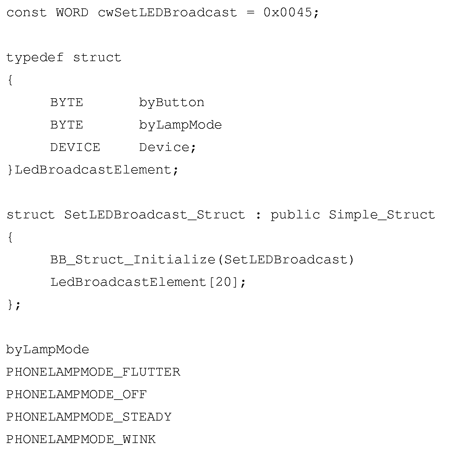
- the TAPI interface 24 can be extended via a so-called "extended service” so that the information element 250 can be processed.
- extended service a so-called "extended service” so that the information element 250 can be processed.
- An example of such an extension is:
Landscapes
- Engineering & Computer Science (AREA)
- Signal Processing (AREA)
- Telephonic Communication Services (AREA)
- Selective Calling Equipment (AREA)
- Mobile Radio Communication Systems (AREA)
Abstract
Description
- Figur 1
- einen Verbund aus Telekommunikationsanlagen,
- Figuren 2A und 2B
- bei einem innerhalb des Verbundes ausgeführten Anruf erzeugte Nachrichten,
- Fig. 3
- ein Rufmodell eines Anwendungsprogramms zu einem Zeitpunkt, zu dem das Telefon des gerufenen Teilnehmers klingelt,
- Figuren 4A und 4B
- bei einer innerhalb des Verbundes ausgeführten Rufübernahme erzeugte Nachrichten,
- Figur 5
- ein Rufmodell des Anwendungsprogramms nach der Rufübernahme, und
- Figur 6
- ein Informationselement mit mehreren Elementeinträgen.
- LED ist erloschen - der Hörer an dem Endgerät, dessen Rufnummer der LED zugeordnet ist, ist aufgelegt,
- LED flackert - das Telefon, das der LED zugeordnet ist, versucht, einen Ruf zu dem Telefon aufzubauen, an dem sich die LED befindet,
- LED blinkt - das der blinkenden LED zugeordnete Telefon wird von einem anderen Telefon gerufen, wobei sich die blinkende LED an einem nicht gerufenen Telefon befindet, und
- LED leuchtet ohne Unterbrechung - der Hörer des der LED zugeordneten Telefons ist abgenommen und der Teilnehmer befindet sich im Gesprächszustand.
- device D4,
- button B1, und
- privateData 0,
- callingDevice D4, und
- calledDirectoryNumber D1,
- initiatedCalls D4C2,
- device D1,
- lamp L2,
- lampMode "flutter",
- device D6,
- lamp L8,
- lampMode "steady",
- initiatedConnection D4C2,
- initiatingDevice D4,
- localConnectionInfo "Initiated",
- cause "make Call",
- callLinkageData G1, T1,
- outboundConnection D3C2,
- networkInterfaceUsed D3,
- callingDevice D4,
- calledDevice D3,
- localConnectionInfo "connected",
- cause "normal",
- callLinkageData G1, T1,
- originatedConnection D4C2,
- callingDevice D4,
- calledDevice D1,
- localConnectionInfo "Connected",
- cause "new Call",
- associatedCalledDevice D3,
- callLinkageData G1, T1
- connection D4C2,
- alertingDevice D1,
- callingDevice D4,
- calledDevice D1,
- originatingNIDConnection D2C1,
- localConnectionInfo "Alerting",
- cause "new Call",
- associatedCallingDevice D2,
- callLinkageData G1, T1,
- privateData partnerLine D3C2,
- connection D3C2,
- alertingDevice D1,
- callingDevice D4,
- calledDevice D1,
- localConnectionInfo "Connected",
- cause "new Call",
- associatedCalledDevice D3,
- callLinkageData G1, T1,
- privateData partnerLine D2C1,
- device D4,
- lamp L4,
- lampMode "steady",
- device D6,
- lamp L7,
- lampMode "wink",
- device D6,
- button B2,
- privateData 0
- callToBeDiverted D3C2,
- newDestination D6,
- divertingConnection D1C1,
- divertingDevice D1,
- newDestination D6,
- lastRedirectionDevice NR,
- localConnectionInfo Null,
- cause "redirected",
- callLinkageData G1, T1
- divertingConnection D3C2,
- divertingDevice D1,
- newDestination D6,
- lastRedirectionDevice NR,
- localConnectionInfo "Connected",
- cause "redirected",
- associatedCalledDevice D8,
- causeLinkageData G1, T1
- device D4,
- lamp L4,
- lampMode "off",
- device D4,
- lamp L6,
- lampMode "steady",
- device D6,
- lamp L1,
- lampMode "off",
- device D1,
- lamp L3,
- lampMode "steady",
- establishedConnection D5C4,
- answeringDevice D6,
- callingDevice D4,
- calledDevice D1,
- localConnectionInfo "Connected",
- cause "newCalled",
- associatedCalledDevice D5,
- callLinkageData G1, T1,
- establishedConnection D8C2,
- answeringDevice D6,
- callingDevice D4,
- calledDevice D1,
- originatingNIDConnection D3C2,
- localConnectionInfo "Connected",
- cause "new Call",
- associatedCallingDevice D8,
- callLinkageData G1, T1,
- den Wert Sechs, um auf das Kennzeichen L6 hinzuweisen,
- den Wert Drei, um den Betriebszustand "Eingeschaltet" zu kennzeichnen, und
- den Wert Vier, um das Kennzeichen D4 zu bezeichnen.
Claims (13)
- Verfahren zum Ansteuern eines Anzeigeelementes (L7) an einem Endgerät (56),
bei dem ein Endgerät (56) an einer vermittlungstechnischen Einrichtung (16) betrieben wird,
bei dem das Endgerät (56) mindestens ein Anzeigeelement (L7) trägt, das Betriebszustände eines dem Anzeigeelement (L7) zugeordneten Endgerätes (46) anzeigt,
und bei dem das Anzeigeelement (L7) mit Hilfe von Signalisierungsnachrichten von der vermittlungstechnischen Einrichtung (16) abhängig von den Betriebszuständen des dem Anzeigeelement (L7) zugeordneten Endgerätes (46) angesteuert wird,
dadurch gekennzeichnet, dass das dem Anzeigeelement (L7) zugeordnete Endgerät (46) an einer anderen vermittlungstechnischen Einrichtung (16) betrieben wird,
dass an die vermittlungstechnische Einrichtung (14) zum Betreiben des Endgerätes (56) mit dem Anzeigeelement (L7) mindestens eine Betriebszustandsnachricht (158) gesendet wird, die den Betriebszustand des dem Anzeigeelement (L7) zugeordneten Endgerätes (46) signalisiert,
und dass die vermittlungstechnische Einrichtung (16) zum Betreiben des Endgerätes (56) mit dem Anzeigeelement (L7) abhängig von der Betriebszustandsnachricht (158) das Anzeigeelement (L7) ansteuert. - Verfahren nach Anspruch 1, dadurch gekennzeichnet, dass in enger räumlicher Beziehung zu dem Anzeigeelement (L7) ein Funktionselement (90) angeordnet ist, bei dessen Betätigung das dem Anzeigeelement (L7) zugeordnete Endgerät (46) erreichbar ist,
dass am Anzeigeelement (L7) ein Betriebszustand angezeigt wird, in dem das dem Anzeigeelement (L7) zugeordnete Endgerät (46) von einem dritten Endgerät (54) aus gerufen wird,
und dass beim Betätigen der Funktionstaste (90) in Zusammenhang mit der Anzeige dieses Betriebszustandes Verfahrensschritte (202 bis 214) zum Heranholen des Rufes ausgeführt werden. - Verfahren nach Anspruch 2, dadurch gekennzeichnet, dass die Verfahrensschritte (202 bis 214) zum Heranholen des Rufes eine Rufumleitung (202) des ankommenden Rufes zu dem Endgerät (54) zu dem Endgerät (56) mit dem Anzeigeelement (L7) enthalten.
- Verfahren nach Anspruch 1, dadurch gekennzeichnet, dass die Betriebszustandsnachricht (158) den Betriebszustand des dem Anzeigeelement (L7) zugeordneten Endgerätes (46) direkt oder indirekt über die Angabe eines Betriebszustandes für das Anzeigeelement (L7) signalisiert.
- Verfahren nach einem der vorhergehenden Ansprüche, dadurch gekennzeichnet, dass die Betriebszustandsnachricht (158) eine Nachricht gemäß CSTA-Protokoll oder gemäß einem auf dem CSTA-Protokoll aufbauendem Protokoll ist.
- Verfahren nach einem der Ansprüche 1 bis 4, dadurch gekennzeichnet, dass die Betriebszustandsnachricht (250) mehrere Betriebszustände (272, 274) für verschiedene Endgeräte (46, 54) signalisiert.
- Verfahren nach einem der vorhergehenden Ansprüche, dadurch gekennzeichnet, dass die vermittlungstechnischen Anlagen (12 bis 16) über ein Datenübertragungsnetz (20) verbunden sind.
- Verfahren nach einem der vorhergehenden Ansprüche, gekennzeichnet durch eine zentrale Steuereinheit (18) der das Betätigen einer Funktionstaste (72, 90) an einem Endgerät (54, 56) signalisiert wird und die die Betriebszustandsnachricht (158) erzeugt.
- Verfahren nach einem der vorhergehenden Ansprüche, dadurch gekennzeichnet, dass die Betriebszustandsnachricht (158) mit Hilfe eines Rufmodells (190) erzeugt wird.
- Vermittlungstechnische Einrichtung (16), insbesondere eine Telekommunikationsanlage (16) oder eine Vermittlungseinrichtung auf einem Personal Computer, welche die Funktionen einer Telekommunikationsanlage (16) erbringt,
mit mindestens einer Anschlusseinheit, über die ein an der vermittlungstechnischen Einrichtung betriebenes Endgerät (56) erreichbar ist,
wobei das Endgerät (56) mindestens ein Anzeigeelement (L7) trägt, das den Betriebszustand eines dem Anzeigeelement (L7) zugeordneten Endgerätes (46) anzeigt,
und mit einer Steuereinheit (80), die das Anzeigeelement (L7) mit Hilfe von Signalisierungsnachrichten abhängig vom Betriebszustand des dem Anzeigeelement (L7) zugeordneten Endgerätes (46) ansteuert,
dadurch gekennzeichnet, dass das dem Anzeigeelement (L7) zugeordnete Endgerät (46) an einer anderen vermittlungstechnischen Einrichtung (16) betrieben wird,
dass die Steuereinheit (80) so aufgebaut ist, dass sie eine von außen kommende Betriebszustandsnachricht (158) bearbeiten kann, welche den Betriebszustand des dem Anzeigeelement (L7) zugeordneten Endgerätes (46) signalisiert,
und dass die Steuereinheit (80) das Anzeigeelement (L7) abhängig von der Betriebszustandsnachricht (158) ansteuert. - Vermittlungstechnische Einrichtung (16) nach Anspruch 10, dadurch gekennzeichnet, dass die vermittlungstechnische Einrichtung (16) so aufgebaut ist, dass bei ihrem Betrieb ein Verfahren nach einem der Ansprüche 1 bis 9 ausgeführt wird.
- Anlagenverbund (10), gekennzeichnet durch mindestens zwei vermittlungstechnische Einrichtungen (12, 16) nach Anspruch 10 oder 11.
- Programm (80) mit einer Befehlsfolge, bei deren Ausführung durch einen Prozessor ein Verfahren nach einem der Ansprüche 1 bis 9 ausgeführt wird.
Applications Claiming Priority (2)
| Application Number | Priority Date | Filing Date | Title |
|---|---|---|---|
| DE10149983A DE10149983A1 (de) | 2001-10-10 | 2001-10-10 | Verfahren zum Ansteuern eines Anzeigeelementes an einem Endgerät und zugehörige Einheiten |
| DE10149983 | 2001-10-10 |
Publications (3)
| Publication Number | Publication Date |
|---|---|
| EP1303122A2 true EP1303122A2 (de) | 2003-04-16 |
| EP1303122A3 EP1303122A3 (de) | 2004-03-03 |
| EP1303122B1 EP1303122B1 (de) | 2018-05-09 |
Family
ID=7702045
Family Applications (1)
| Application Number | Title | Priority Date | Filing Date |
|---|---|---|---|
| EP02102419.5A Expired - Lifetime EP1303122B1 (de) | 2001-10-10 | 2002-10-07 | Anzeige von Rufzuständen eines Endgeräts an einem anderen Endgerät in einem TK-Anlagenverbund |
Country Status (3)
| Country | Link |
|---|---|
| US (1) | US7751544B2 (de) |
| EP (1) | EP1303122B1 (de) |
| DE (1) | DE10149983A1 (de) |
Families Citing this family (9)
| Publication number | Priority date | Publication date | Assignee | Title |
|---|---|---|---|---|
| DE10344772B4 (de) * | 2003-09-26 | 2006-11-09 | Siemens Ag | Verfahren zur Übertragung von Multimediadaten zwischen zumindest einer Kommunikationseinrichtung und zumindest einem Rechnersystem |
| US7417982B2 (en) * | 2003-11-19 | 2008-08-26 | Dialogic Corporation | Hybrid switching architecture having dynamically assigned switching models for converged services platform |
| US20050144621A1 (en) * | 2003-12-23 | 2005-06-30 | Millbery Trevor A. | CSTA services library |
| KR20100042678A (ko) * | 2008-10-02 | 2010-04-27 | 삼성전자주식회사 | 통신 장치에서 프레젠스 서비스를 제공하기 위한 장치 및 방법 |
| TWI416936B (zh) * | 2010-09-27 | 2013-11-21 | Tecom Co Ltd | 遠端電話話機的忙線提示系統及其方法 |
| US8457292B2 (en) * | 2010-12-08 | 2013-06-04 | Tecom Co., Ltd. | Busy lamp field system for remote telephones and method for the same |
| US9749422B2 (en) | 2014-12-05 | 2017-08-29 | Unify Gmbh & Co. Kg | Method and system for telecommunication device monitoring |
| DE102015007857A1 (de) | 2015-06-18 | 2016-12-22 | Unify Gmbh & Co. Kg | Verfahren zum Aufbau einer Telekommunikationsverbindung in einem Telekommunikationssystem und Telekommunikationssystem |
| DE102015010706B4 (de) | 2015-08-14 | 2017-10-05 | Unify Gmbh & Co. Kg | Verfahren, Vorrichtung und System für ein Verfahren zum Einschalten einer Überwachung von Überwachungsobjekten in einer Computer-Implementierten Telekommunikationsumgebung |
Family Cites Families (14)
| Publication number | Priority date | Publication date | Assignee | Title |
|---|---|---|---|---|
| US4510351A (en) * | 1982-10-28 | 1985-04-09 | At&T Bell Laboratories | ACD Management information system |
| US4644528A (en) * | 1985-02-07 | 1987-02-17 | At&T Bell Laboratories | Terminating port determination in a distributed control switching system using a distributed database |
| US4790004A (en) * | 1986-12-10 | 1988-12-06 | American Telephone And Telegraph Company, At&T Information Systems | Implied principal busy status indicator for covered calls |
| US4850011A (en) * | 1988-01-13 | 1989-07-18 | Redcom Laboratories, Inc. | Key telephone system providing selection of key or PBX operational modes |
| US5608779A (en) * | 1994-11-08 | 1997-03-04 | Motorola, Inc. | Method for communications between mobile units using single and multiple switching center configurations |
| EP0752188B1 (de) * | 1994-12-19 | 2002-02-20 | Koninklijke Philips Electronics N.V. | Fernmeldevermittlungsanlage |
| WO1996027266A1 (en) | 1995-02-28 | 1996-09-06 | Philips Electronics N.V. | Telecommunication system |
| US6052461A (en) * | 1997-07-17 | 2000-04-18 | Ericsson Inc. | Method and apparatus for maintaining real-time busy status information of telephone extensions in a private branch exchange |
| US5937035A (en) * | 1997-09-15 | 1999-08-10 | Lucent Technologies Inc. | Interswitch telephone status monitoring |
| US6363142B1 (en) * | 1998-08-25 | 2002-03-26 | Siemens Information And Communication Networks, Inc. | Network directed call pickup service |
| US6731609B1 (en) * | 1998-12-31 | 2004-05-04 | Aspect Communications Corp. | Telephony system for conducting multimedia telephonic conferences over a packet-based network |
| FI19992246L (fi) * | 1999-10-18 | 2001-04-19 | Nokia Networks Oy | Järjestely tietoliikenneverkkojen yhdistämiseksi |
| DE10016244A1 (de) * | 2000-03-31 | 2001-10-04 | Siemens Ag | Verfahren zur Zustandssignalisierung eines Teilnehmeranschlusses in einem Kommunikationsnetz mit Kommunikationsanlagen |
| US6950876B2 (en) * | 2001-03-19 | 2005-09-27 | Lucent Technologies Inc. | Multiple-protocol home location register and method of use |
-
2001
- 2001-10-10 DE DE10149983A patent/DE10149983A1/de not_active Withdrawn
-
2002
- 2002-10-07 EP EP02102419.5A patent/EP1303122B1/de not_active Expired - Lifetime
- 2002-10-10 US US10/268,088 patent/US7751544B2/en not_active Expired - Fee Related
Also Published As
| Publication number | Publication date |
|---|---|
| EP1303122B1 (de) | 2018-05-09 |
| US20030154245A1 (en) | 2003-08-14 |
| DE10149983A1 (de) | 2003-04-30 |
| EP1303122A3 (de) | 2004-03-03 |
| US7751544B2 (en) | 2010-07-06 |
Similar Documents
| Publication | Publication Date | Title |
|---|---|---|
| DE69921062T2 (de) | Fernsprechkonferenzgerät und -verfahren | |
| EP0350844B1 (de) | Verfahren zum Übermitteln endgerätebestimmender Programmparameterdaten von einer Kommunikationsanlage zu Kommunikationsendgeräten | |
| EP0731618B1 (de) | Verfahren zum Steuern eines Zugangsnetzes sowie Vermittlungsstelle und Zugangsnetz damit | |
| EP1303122B1 (de) | Anzeige von Rufzuständen eines Endgeräts an einem anderen Endgerät in einem TK-Anlagenverbund | |
| EP0106318B1 (de) | Fernsprechapparat mit optischen Anzeigeeinrichtungen | |
| EP1091551B1 (de) | Verfahren zum Betreiben einer Vermittlungseinrichtung unter Nutzung verschiedener Signalisierungsprotokolle | |
| DE10000809A1 (de) | Diensteinheit zur Unterstützung des Aufbaus von Kommunikationsverbindungen | |
| EP1269766B1 (de) | Bereitstellen von ergänzenden diensten in einem paketvermittelnden kommunikationsnetz | |
| EP0589248A2 (de) | Verfahren und Anordnung zur Anzeige von Rufnummern an Fernmeldeendgeräten einer Fernmeldenebenstellenanlage | |
| DE1762884B2 (de) | Schaltungsanordnung zur bereitstellung von sonderdiensten in fernmelde insbesondere fernsprechvermittlungsanlagen | |
| EP1705889B1 (de) | Verfahren zum schnellen Aufbauen einer Nutzdatenverbindung zwischen Kommunikationsendeinrichtungen | |
| EP1124361A2 (de) | Verfahren zum Steuern zusätzlicher Leistungsfunktionen sowie zugehöriges Kommunikationsnetz und zugehöriges Programm | |
| EP0529343B1 (de) | Verfahren zur Herstellung einer Verbindung zwischen einem an eine Kommunikationsanlage angeschlossenen Kommunikationsendegerät mit einer Mehrzahl von weiteren Geräten | |
| EP1091535A2 (de) | Verfahren und elektronische Einheiten zur Übertragung von Sprachdaten in Datenpaketen unter Nutzung zusätzlicher Leistungsmerkmale sowie zugehörige Einheiten und Programme | |
| DE4020618C2 (de) | Verfahren zur Signalisierung von Fernsprech-Rückrufverbindungen | |
| EP0477627B1 (de) | Verfahren zum Verbinden von Kommunikationsendgeräten in diensteintegrierenden Kommunikationsnetzen | |
| EP0535602A2 (de) | Programmgesteuerte Kommunikationsanlage, bei der eine Verbindungsanforderung gleichzeitig an mehrere Kommunikationsendgeräte signalisiert wird | |
| DE10145987A1 (de) | Verfahren zur Auswahl eines Leistungsmerkmals und zugehörige Einheiten | |
| DE1293868B (de) | Schaltungsanordnung fuer Fernsprechnebenstellenanlagen mit Umlegeeinrichtungen | |
| DE19809835C2 (de) | Gezielte Anrufselektierung "Distinctive Call" | |
| DE10241179A1 (de) | Verfahren zum Aufbau einer Nutzdatenverbindung zwischen Endpunkten in einer VoIP-Anordnung | |
| DE4420886A1 (de) | Kommunikationsvermittlungssystem mit einem Leistungsmerkmalsystem und einem Basisvermittlungssystem | |
| DE19948090B4 (de) | Verfahren zum Anschliessen eines Endgerätes an eine Telekommunikationsanlage sowie zugehörige elektronische Baueinheiten | |
| DE2819435C2 (de) | Fernmelde-, insbesondere Betriebsfernsprechanlagen, mit Bedienungsplätzen und über zentralgesteuerte Anschalteinrichtungen verbindbaren Übertragungseinrichtungen (Anruf- und Belegungskennungen) | |
| EP1282293A1 (de) | Verfahren zur Rufbearbeitung in einem Telekommunikationsnetz sowie zugehörige Einheiten |
Legal Events
| Date | Code | Title | Description |
|---|---|---|---|
| PUAI | Public reference made under article 153(3) epc to a published international application that has entered the european phase |
Free format text: ORIGINAL CODE: 0009012 |
|
| AK | Designated contracting states |
Designated state(s): AT BE BG CH CY CZ DE DK EE ES FI FR GB GR IE IT LI LU MC NL PT SE SK TR |
|
| AX | Request for extension of the european patent |
Extension state: AL LT LV MK RO SI |
|
| PUAL | Search report despatched |
Free format text: ORIGINAL CODE: 0009013 |
|
| AK | Designated contracting states |
Kind code of ref document: A3 Designated state(s): AT BE BG CH CY CZ DE DK EE ES FI FR GB GR IE IT LI LU MC NL PT SE SK TR |
|
| AX | Request for extension of the european patent |
Extension state: AL LT LV MK RO SI |
|
| RIC1 | Information provided on ipc code assigned before grant |
Ipc: 7H 04M 3/42 A Ipc: 7H 04M 7/00 B |
|
| 17P | Request for examination filed |
Effective date: 20040322 |
|
| AKX | Designation fees paid |
Designated state(s): DE FR GB IT |
|
| 17Q | First examination report despatched |
Effective date: 20090508 |
|
| RAP1 | Party data changed (applicant data changed or rights of an application transferred) |
Owner name: SIEMENS ENTERPRISE COMMUNICATIONS GMBH & CO. KG |
|
| RAP1 | Party data changed (applicant data changed or rights of an application transferred) |
Owner name: UNIFY GMBH & CO. KG |
|
| RAP1 | Party data changed (applicant data changed or rights of an application transferred) |
Owner name: UNIFY GMBH & CO. KG |
|
| GRAP | Despatch of communication of intention to grant a patent |
Free format text: ORIGINAL CODE: EPIDOSNIGR1 |
|
| INTG | Intention to grant announced |
Effective date: 20171205 |
|
| GRAS | Grant fee paid |
Free format text: ORIGINAL CODE: EPIDOSNIGR3 |
|
| GRAA | (expected) grant |
Free format text: ORIGINAL CODE: 0009210 |
|
| AK | Designated contracting states |
Kind code of ref document: B1 Designated state(s): DE FR GB IT |
|
| REG | Reference to a national code |
Ref country code: GB Ref legal event code: FG4D Free format text: NOT ENGLISH |
|
| REG | Reference to a national code |
Ref country code: DE Ref legal event code: R096 Ref document number: 50216288 Country of ref document: DE |
|
| REG | Reference to a national code |
Ref country code: DE Ref legal event code: R097 Ref document number: 50216288 Country of ref document: DE |
|
| RIC2 | Information provided on ipc code assigned after grant |
Ipc: H04M 7/00 20060101ALI20040109BHEP Ipc: H04M 3/42 20060101AFI20040109BHEP |
|
| PG25 | Lapsed in a contracting state [announced via postgrant information from national office to epo] |
Ref country code: IT Free format text: LAPSE BECAUSE OF FAILURE TO SUBMIT A TRANSLATION OF THE DESCRIPTION OR TO PAY THE FEE WITHIN THE PRESCRIBED TIME-LIMIT Effective date: 20180509 |
|
| PLBE | No opposition filed within time limit |
Free format text: ORIGINAL CODE: 0009261 |
|
| STAA | Information on the status of an ep patent application or granted ep patent |
Free format text: STATUS: NO OPPOSITION FILED WITHIN TIME LIMIT |
|
| 26N | No opposition filed |
Effective date: 20190212 |
|
| REG | Reference to a national code |
Ref country code: DE Ref legal event code: R119 Ref document number: 50216288 Country of ref document: DE |
|
| GBPC | Gb: european patent ceased through non-payment of renewal fee |
Effective date: 20181007 |
|
| PG25 | Lapsed in a contracting state [announced via postgrant information from national office to epo] |
Ref country code: DE Free format text: LAPSE BECAUSE OF NON-PAYMENT OF DUE FEES Effective date: 20190501 |
|
| PG25 | Lapsed in a contracting state [announced via postgrant information from national office to epo] |
Ref country code: FR Free format text: LAPSE BECAUSE OF NON-PAYMENT OF DUE FEES Effective date: 20181031 |
|
| PG25 | Lapsed in a contracting state [announced via postgrant information from national office to epo] |
Ref country code: GB Free format text: LAPSE BECAUSE OF NON-PAYMENT OF DUE FEES Effective date: 20181007 |