EP1302703A2 - Einrichtung und Verfahren zum Steuern eines Antriebsstrangsystemes - Google Patents
Einrichtung und Verfahren zum Steuern eines Antriebsstrangsystemes Download PDFInfo
- Publication number
- EP1302703A2 EP1302703A2 EP02102248A EP02102248A EP1302703A2 EP 1302703 A2 EP1302703 A2 EP 1302703A2 EP 02102248 A EP02102248 A EP 02102248A EP 02102248 A EP02102248 A EP 02102248A EP 1302703 A2 EP1302703 A2 EP 1302703A2
- Authority
- EP
- European Patent Office
- Prior art keywords
- torque
- engine
- torque converter
- powertrain
- transmission
- Prior art date
- Legal status (The legal status is an assumption and is not a legal conclusion. Google has not performed a legal analysis and makes no representation as to the accuracy of the status listed.)
- Granted
Links
Images


Classifications
-
- F—MECHANICAL ENGINEERING; LIGHTING; HEATING; WEAPONS; BLASTING
- F02—COMBUSTION ENGINES; HOT-GAS OR COMBUSTION-PRODUCT ENGINE PLANTS
- F02D—CONTROLLING COMBUSTION ENGINES
- F02D41/00—Electrical control of supply of combustible mixture or its constituents
- F02D41/02—Circuit arrangements for generating control signals
- F02D41/021—Introducing corrections for particular conditions exterior to the engine
- F02D41/0215—Introducing corrections for particular conditions exterior to the engine in relation with elements of the transmission
- F02D41/022—Introducing corrections for particular conditions exterior to the engine in relation with elements of the transmission in relation with the clutch status
-
- F—MECHANICAL ENGINEERING; LIGHTING; HEATING; WEAPONS; BLASTING
- F02—COMBUSTION ENGINES; HOT-GAS OR COMBUSTION-PRODUCT ENGINE PLANTS
- F02D—CONTROLLING COMBUSTION ENGINES
- F02D41/00—Electrical control of supply of combustible mixture or its constituents
- F02D41/02—Circuit arrangements for generating control signals
- F02D41/14—Introducing closed-loop corrections
- F02D41/1497—With detection of the mechanical response of the engine
-
- F—MECHANICAL ENGINEERING; LIGHTING; HEATING; WEAPONS; BLASTING
- F16—ENGINEERING ELEMENTS AND UNITS; GENERAL MEASURES FOR PRODUCING AND MAINTAINING EFFECTIVE FUNCTIONING OF MACHINES OR INSTALLATIONS; THERMAL INSULATION IN GENERAL
- F16H—GEARING
- F16H59/00—Control inputs to control units of change-speed-, or reversing-gearings for conveying rotary motion
- F16H59/14—Inputs being a function of torque or torque demand
-
- F—MECHANICAL ENGINEERING; LIGHTING; HEATING; WEAPONS; BLASTING
- F16—ENGINEERING ELEMENTS AND UNITS; GENERAL MEASURES FOR PRODUCING AND MAINTAINING EFFECTIVE FUNCTIONING OF MACHINES OR INSTALLATIONS; THERMAL INSULATION IN GENERAL
- F16H—GEARING
- F16H61/00—Control functions within control units of change-speed- or reversing-gearings for conveying rotary motion ; Control of exclusively fluid gearing, friction gearing, gearings with endless flexible members or other particular types of gearing
- F16H61/66—Control functions within control units of change-speed- or reversing-gearings for conveying rotary motion ; Control of exclusively fluid gearing, friction gearing, gearings with endless flexible members or other particular types of gearing specially adapted for continuously variable gearings
- F16H61/662—Control functions within control units of change-speed- or reversing-gearings for conveying rotary motion ; Control of exclusively fluid gearing, friction gearing, gearings with endless flexible members or other particular types of gearing specially adapted for continuously variable gearings with endless flexible members
- F16H61/66272—Control functions within control units of change-speed- or reversing-gearings for conveying rotary motion ; Control of exclusively fluid gearing, friction gearing, gearings with endless flexible members or other particular types of gearing specially adapted for continuously variable gearings with endless flexible members characterised by means for controlling the torque transmitting capability of the gearing
-
- F—MECHANICAL ENGINEERING; LIGHTING; HEATING; WEAPONS; BLASTING
- F02—COMBUSTION ENGINES; HOT-GAS OR COMBUSTION-PRODUCT ENGINE PLANTS
- F02D—CONTROLLING COMBUSTION ENGINES
- F02D2200/00—Input parameters for engine control
- F02D2200/02—Input parameters for engine control the parameters being related to the engine
- F02D2200/10—Parameters related to the engine output, e.g. engine torque or engine speed
- F02D2200/1002—Output torque
- F02D2200/1004—Estimation of the output torque
-
- F—MECHANICAL ENGINEERING; LIGHTING; HEATING; WEAPONS; BLASTING
- F02—COMBUSTION ENGINES; HOT-GAS OR COMBUSTION-PRODUCT ENGINE PLANTS
- F02D—CONTROLLING COMBUSTION ENGINES
- F02D2200/00—Input parameters for engine control
- F02D2200/02—Input parameters for engine control the parameters being related to the engine
- F02D2200/10—Parameters related to the engine output, e.g. engine torque or engine speed
- F02D2200/1006—Engine torque losses, e.g. friction or pumping losses or losses caused by external loads of accessories
-
- F—MECHANICAL ENGINEERING; LIGHTING; HEATING; WEAPONS; BLASTING
- F02—COMBUSTION ENGINES; HOT-GAS OR COMBUSTION-PRODUCT ENGINE PLANTS
- F02D—CONTROLLING COMBUSTION ENGINES
- F02D2250/00—Engine control related to specific problems or objectives
- F02D2250/18—Control of the engine output torque
-
- F—MECHANICAL ENGINEERING; LIGHTING; HEATING; WEAPONS; BLASTING
- F02—COMBUSTION ENGINES; HOT-GAS OR COMBUSTION-PRODUCT ENGINE PLANTS
- F02D—CONTROLLING COMBUSTION ENGINES
- F02D2400/00—Control systems adapted for specific engine types; Special features of engine control systems not otherwise provided for; Power supply, connectors or cabling for engine control systems
- F02D2400/12—Engine control specially adapted for a transmission comprising a torque converter or for continuously variable transmissions
-
- F—MECHANICAL ENGINEERING; LIGHTING; HEATING; WEAPONS; BLASTING
- F16—ENGINEERING ELEMENTS AND UNITS; GENERAL MEASURES FOR PRODUCING AND MAINTAINING EFFECTIVE FUNCTIONING OF MACHINES OR INSTALLATIONS; THERMAL INSULATION IN GENERAL
- F16H—GEARING
- F16H59/00—Control inputs to control units of change-speed-, or reversing-gearings for conveying rotary motion
- F16H59/14—Inputs being a function of torque or torque demand
- F16H2059/147—Transmission input torque, e.g. measured or estimated engine torque
-
- F—MECHANICAL ENGINEERING; LIGHTING; HEATING; WEAPONS; BLASTING
- F16—ENGINEERING ELEMENTS AND UNITS; GENERAL MEASURES FOR PRODUCING AND MAINTAINING EFFECTIVE FUNCTIONING OF MACHINES OR INSTALLATIONS; THERMAL INSULATION IN GENERAL
- F16H—GEARING
- F16H59/00—Control inputs to control units of change-speed-, or reversing-gearings for conveying rotary motion
- F16H59/36—Inputs being a function of speed
- F16H59/46—Inputs being a function of speed dependent on a comparison between speeds
- F16H2059/465—Detecting slip, e.g. clutch slip ratio
- F16H2059/467—Detecting slip, e.g. clutch slip ratio of torque converter
Definitions
- the present invention relates generally to a system and a method of controlling a vehicle equipped with a continuously variable transmission, and more particularly to estimating an input torque to a continuously variable transmission.
- a CVT which typically comprises a metal belt sliding on two pulleys (a primary pulley coupled to the engine and a secondary pulley coupled to the drive shaft)
- the gear ratio can be continuously changed by applying hydraulic pressures to the pulleys and thus changing the belt winding radius.
- the powertrain of the vehicle equipped with CVT can be controlled such that actual engine speed is matched to the desired engine speed at which most efficient fuel consumption can be achieved.
- a CVT equipped vehicle can achieve improved fuel efficiency throughout the entire range of vehicle speeds made available by the infinitely variable driveline as compared to vehicles with the conventional automatic transmission.
- a method for controlling a powertrain of a vehicle having an engine coupled to a continuously variable transmission by means of a torque converter characterised in that the method comprises providing an indication that a torque converter clutch is unlocked, learning a powertrain torque correction value when said indication is provided, adjusting a powertrain torque estimate based on said correction value and determining a signal for controlling a transmission clamping force based on said adjusted powertrain torque estimate.
- the powertrain torque may be a transmission input torque.
- Said powertrain torque estimate may be based on an operating condition.
- the operating condition may be at least one of mass airflow and engine speed.
- Said powertrain torque correction value may be determined based on a ratio of an engine speed and a turbine speed.
- the clamping force may be further determined based on geometric properties of a transmission pulley system.
- a method for controlling a powertrain of a vehicle having an engine coupled to a continuously variable transmission by a torque converter coupled between the engine and the continuously variable transmission comprises estimating a first powertrain torque based on a torque converter characteristic; estimating a second powertrain torque based on an engine operating condition and said first estimated powertrain torque and calculating a required transmission clamping force based on said second estimated powertrain torque.
- Said first powertrain torque may be estimated when a torque converter clutch is unlocked.
- Said torque converter characteristic may be a torque converter ratio or may be a capacity factor.
- Said first powertrain torque estimation may be further based on a ratio of a transmission input speed and an engine speed.
- Said engine operating condition may be at least one of mass airflow and engine speed.
- a system for controlling the powertrain of a motor vehicle having an engine, a continuously variable transmission a torque converter having a torque converter clutch coupled between said engine and said continuously variable transmission characterised in that the system comprises a controller for determining a torque correction value when said torque converter clutch is unlocked, and calibrating an engine model based on said correction value, said controller calculating a transmission input torque based on said calibrated engine model, and adjusting a transmission clamping force based on said transmission input force.
- Said engine model is based on an engine operating condition.
- Said engine operating condition is at least one of mass airflow and engine speed.
- Said correction value may be calculated based on a torque converter ratio.
- Said correction value may be calculated based on the physical properties of said torque converter.
- Said controller may further determine said transmission clamping force based on geometric properties of a transmission pulley system.
- a motor vehicle having an engine, a continuously variable transmission a torque converter having a torque converter clutch coupled between said engine and said continuously variable transmission and a system for controlling the powertrain of a vehicle in accordance with the second aspect of the invention.
- the present invention is independent of the particular underlying engine technology and configuration. As such, the present invention may be used in a variety of types of internal combustion engines, such as conventional engines, in addition to direct injection stratified charge (DISC) or direct injection spark ignition engines (DISI).
- DISC direct injection stratified charge
- DISI direct injection spark ignition engines
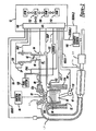
- FIG. 1 A block diagram illustrating an engine control system and method for a representative internal combustion engine fitted to a motor vehicle is shown in Figure 1.
- Torque converter 9 is shown coupled to torque converter 9 via crankshaft 13. Torque converter 9 is also coupled to transmission 11 via turbine shaft 17, which is also known as a transmission input shaft. Torque converter 9 has a bypass clutch (not shown), which can be engaged, disengaged, or partially engaged. When bypass clutch is disengaged, torque converter 9 is said to be in an unlocked state.
- Transmission 11 is an electronically controlled continuously variable transmission (CVT), comprising an input pulley 8 having a radius R i that is adjusted relative to the radius R o of an output pulley 7, affecting the movement of a belt 6, and thus providing a continuously variable transmission gear ratio to a drive axle 5.
- CVT continuously variable transmission
- Both the input and the output pulleys are equipped with pulley speed sensors (nor shown), which provide signals that are used in determining transmission ratio.
- the winding radius of the belt is changed by applying hydraulic pressures to the input and output pulleys.
- Internal combustion engine 10 has a plurality of cylinders, one cylinder of which is shown in Figure 2, is controlled by electronic engine controller 12.
- Engine 10 includes combustion chamber 30 and cylinder walls 32 with piston 36 positioned therein and connected to crankshaft 40.
- Combustion chamber 30 communicates with intake manifold 44 and exhaust manifold 48 via respective intake valve 52a and exhaust valve 54A.
- Exhaust gas oxygen sensor 16 is coupled to exhaust manifold 48 of engine 10 upstream of catalytic converter 20.
- sensor 16 is a HEGO sensor as is known to those skilled in the art.
- Intake manifold 44 communicates with throttle body 58 via throttle plate 62. Throttle plate 62 is controlled by an electric motor which receives a signal from an ETC driver (not shown). The ETC driver receives a control signal (DC) from controller 12. Intake manifold 44 is also shown having fuel injector 66 coupled thereto for delivering fuel in proportion to the pulse width of signal (fpw) from controller 12. Fuel is delivered to fuel injector 68 by a conventional fuel system 130 including a fuel tank, fuel pump, and fuel rail.
- Engine 10 further includes conventional distributorless ignition system 88 to provide ignition spark to combustion chamber 30 via spark plug 92 in response to controller 12.
- controller 12 is a conventional microcomputer including: microprocessor unit 102, input/output ports 106, electronic memory chip which is an electronically programmable memory in this particular example, random access memory 108, 110 and a conventional data bus.
- Controller 12 receives various signals from sensors coupled to engine 10, in addition to those signals previously discussed, including: measurements of inducted mass air flow (MAF) from mass air flow sensor 94 coupled to throttle body 58 (alternatively, inducted air flow can be determined form a manifold absolute pressure (MAP) sensor 122 located in the engine intake manifold, and engine speed); engine coolant temperature (ECT) from temperature sensor 112 coupled to cooling jacket 114; a measurement of throttle position (TP) from throttle position sensor 120 coupled to throttle plate 62; a measurement of turbine speed (W t ) from turbine speed sensor used to measure the speed of shaft 17, and a profile ignition pickup signal (PIP) from Hall effect sensor 118 coupled to crankshaft 40 indicating an engine speed (W e ).
- turbine speed may be determined from vehicle speed and gear ratio.
- Accelerator pedal position (PP) is measured by pedal position sensor and sent to controller 12.
- an air bypass valve (not shown) can be installed to allow a controlled amount of air to bypass throttle plate 62.
- the air bypass valve (not shown) receives a control signal (not shown) from controller 12.
- the diagram in Figure 3 generally represents operation of one embodiment of a system or method according to the present invention.
- the diagram may represent one or more of any number of processing strategies such as event-driven, interrupt-driven, multi-tasking, multi-threading, and the like.
- various steps or functions illustrated may be performed in the sequence illustrated, in parallel, or in some cases omitted.
- the order of processing is not necessarily required to achieve the objects, features and advantages of the invention, but is provided for ease of illustration and description.
- step 100 adaptive parameters b 0 and b 1 are initialized and set to 0 and 1 respectively.
- Parameters b 0 and b 1 are slope and offset coefficients for the relationship between the engine torque based estimate of the CVT input torque and the torque converter torque based estimate of the CVT input torque.
- net engine torque, T net is estimated as a difference between T ind (engine indicated torque estimated based on engine operating conditions, such as air-charge, spark advance, air-fuel ratio, air and coolant temperatures, etc), and T f / a (torque due to friction, pumping, and accessory loading losses).
- T f / a could be determined from a look-up table as a function of engine operating conditions and the type of accessories that are engaged (i.e., air-conditioning, power steering, etc).
- the engine torque-based estimate of the input torque to the CVT, T cvt is determined: wherein is the torque converter torque ratio determined experimentally as a function of engine speed and turbine speed, and T pl is the torque converter pumping loss that could be determined from a look-up table as a function of engine speed, or torque converter speed ratio.
- the input torque into the CVT is estimated by estimating engine brake torque based on operating conditions, reducing it by the converter pumping torque, and multiplying the result by the converter torque ratio determined as a function of the converter speed ratio.
- the clamping force could be determined from a look-up table based on the corrected CVT input torque estimate and the transmission ratio, which is determined based on operating conditions, such as engine speed, transmission input speed, and input and output pulley speeds.
- the clamping force is applied by controlling hydraulic line pressure in the CVT.
- the corrected transmission torque estimate could be used for improved shift control in a conventional automatic transmission, various engine torque and emission control strategies, etc.
- a CVT system may require a controller for determining a proper amount of clamping forces to be applied to the primary and secondary pulleys to prevent the belt from slipping.
- the clamping force to the secondary pulley is determined based on the amount of estimated CVT input torque, and the clamping force to the primary pulley is adjusted such that desired transmission ratio is achieved.
- the inventors herein have further recognized that the accuracy of the CVT input torque estimate is important to the proper operation of the Continuously Variable Transmission. If the torque estimate is too low, the clamping force will also be too low, and the belt can slip, which may result in rapid degradation and wear of the belt.
- the CVT requires much higher clamping forces than the conventional transmission (typically 2-4 times higher) to prevent the belt from slipping on the pulleys. Therefore, if the clamping force estimate is too high due to inaccuracies in the CVT input torque estimate, the fuel economy penalty could be very significant. In other words, over- or underestimating the CVT input torque could result in reduced vehicle durability, fuel economy and overall customer satisfaction.
- the CVT input torque is estimated based on the information provided by sensors such as the engine speed sensor, mass airflow sensor, air-fuel ratio sensor, etc.
- sensors such as the engine speed sensor, mass airflow sensor, air-fuel ratio sensor, etc.
- the inventors have further recognized that it may be possible for these sensor signals to drift in range due to electrical degradation or chemical contamination.
- the resulting secondary pulley clamping force estimate which is based on the CVT input torque estimate may also not be as accurate as possible.
- the inventors have additionally recognized that an accurate estimate of the CVT input torque could be obtained based on a torque converter ratio when the torque converter clutch is unlocked.
- the accuracy of this estimate is affected mainly by the variations of the torque converter ratio (which depend on the converter design tolerances), and may be more accurate than the engine torque-based estimate, which is affected by engine, sensor and torque converter tolerances.
- a method for controlling a powertrain of a vehicle having an engine coupled to a continuously variable transmission, the vehicle further having a torque converter coupled between the engine and the transmission including: providing an indication that a torque converter clutch is unlocked; learning a powertrain torque correction value when said indication is provided; adjusting a powertrain torque estimate based on said correction value; and determining a control signal for adjusting a transmission clamping force based on said adjusted powertrain torque estimate.
- this method determines correction coefficients when the torque converter clutch is unlocked. These coefficients are then used to calibrate an engine model such that the error between the more accurate torque converter-based CVT input torque estimate and the less accurate engine-based CVT input torque estimate is minimized.
- a transmission clamping force based on an adjusted powertrain torque estimate, it is possible to provide just enough force to transmit the torque, without providing too much force, which can waste fuel.
- An advantage of the above aspect of invention is that improved fuel efficiency can be achieved by eliminating overestimating of clamping forces. Also, improved reliability and customer satisfaction will be achieved by preventing CVT belt slippage due to clamping force underestimation.
Applications Claiming Priority (2)
| Application Number | Priority Date | Filing Date | Title |
|---|---|---|---|
| US09/976,962 US6427109B1 (en) | 2001-10-11 | 2001-10-11 | Powertrain torque estimate |
| US976962 | 2001-10-11 |
Publications (3)
| Publication Number | Publication Date |
|---|---|
| EP1302703A2 true EP1302703A2 (de) | 2003-04-16 |
| EP1302703A3 EP1302703A3 (de) | 2006-05-10 |
| EP1302703B1 EP1302703B1 (de) | 2008-02-20 |
Family
ID=25524675
Family Applications (1)
| Application Number | Title | Priority Date | Filing Date |
|---|---|---|---|
| EP02102248A Expired - Fee Related EP1302703B1 (de) | 2001-10-11 | 2002-08-30 | Einrichtung und Verfahren zum Steuern eines Antriebsstrangsystemes |
Country Status (4)
| Country | Link |
|---|---|
| US (1) | US6427109B1 (de) |
| EP (1) | EP1302703B1 (de) |
| JP (1) | JP2003130201A (de) |
| DE (1) | DE60225102T2 (de) |
Families Citing this family (19)
| Publication number | Priority date | Publication date | Assignee | Title |
|---|---|---|---|---|
| GB2368924B (en) * | 2000-09-26 | 2004-12-15 | Ford Global Tech Inc | A method and apparatus for controlling a powertrain |
| US6568257B2 (en) * | 2001-10-18 | 2003-05-27 | Ford Global Technologies, Llc | Cylinder air charge estimate |
| US7236869B2 (en) * | 2004-04-30 | 2007-06-26 | General Motors Corporation | Blended torque estimation for automatic transmission systems |
| US7069767B2 (en) * | 2004-05-21 | 2006-07-04 | General Motors Corporation | Method of determining initial transmission calibration |
| US20060047400A1 (en) * | 2004-08-25 | 2006-03-02 | Raj Prakash | Method and apparatus for braking and stopping vehicles having an electric drive |
| US7643929B2 (en) * | 2006-10-10 | 2010-01-05 | Gm Global Technology Operations, Inc. | Method for adapting torque model for improved zero torque identification |
| JP4692523B2 (ja) * | 2007-07-05 | 2011-06-01 | トヨタ自動車株式会社 | 車両の制御装置および制御方法 |
| JP4363486B2 (ja) * | 2008-01-22 | 2009-11-11 | トヨタ自動車株式会社 | 無段変速機の制御装置および制御方法 |
| US7844404B2 (en) * | 2008-12-17 | 2010-11-30 | Honeywell International Inc. | Systems and methods for determining engine torque values |
| FR2943024B1 (fr) * | 2009-03-10 | 2012-07-13 | Peugeot Citroen Automobiles Sa | Procede de determination du couple inertiel et du couple de perte moteur |
| JP5645414B2 (ja) * | 2010-02-03 | 2014-12-24 | 本田技研工業株式会社 | クラッチ制御装置 |
| US20130139614A1 (en) * | 2011-12-05 | 2013-06-06 | David C. Johnson | Portable torque work station and associated torquing method |
| US8834320B2 (en) * | 2012-01-11 | 2014-09-16 | Ford Global Technologies, Llc | Hybrid vehicle and control for a clutch engaging event |
| US8924124B2 (en) | 2012-01-17 | 2014-12-30 | Ford Global Technologies, Llc | Method and system for engine torque control |
| US8956264B2 (en) * | 2012-06-26 | 2015-02-17 | Ford Global Technologies | Control system and method for a vehicle transmission |
| CA2895931A1 (en) * | 2012-12-21 | 2014-06-26 | Bombardier Recreational Products Inc. | Method and system for limiting belt slip in a continuously variable transmission |
| US9541013B2 (en) | 2012-12-21 | 2017-01-10 | Bombardier Recreational Products Inc. | Method and system for limiting belt slip in a continuously variable transmission |
| EP2796692A1 (de) * | 2013-04-24 | 2014-10-29 | Robert Bosch GmbH | Verfahren für den Betrieb eines Verbrennungsmotors |
| US10196067B2 (en) * | 2016-07-21 | 2019-02-05 | Ford Global Technologies, Llc | Method and system for controlling water injection |
Family Cites Families (16)
| Publication number | Priority date | Publication date | Assignee | Title |
|---|---|---|---|---|
| US4953091A (en) * | 1988-10-24 | 1990-08-28 | Ford Motor Company | Automatic transmission torque converter clutch control |
| DE3934506C1 (de) | 1989-10-16 | 1991-05-08 | Ford-Werke Ag, 5000 Koeln, De | |
| JP2873615B2 (ja) | 1990-09-11 | 1999-03-24 | 株式会社ユニシアジェックス | 流体伝動装置付変速機の作動油圧制御装置 |
| US5452207A (en) | 1992-11-09 | 1995-09-19 | Ford Motor Company | Robust torque estimation using multiple models |
| US5514047A (en) | 1993-03-08 | 1996-05-07 | Ford Motor Company | Continuously variable transmission |
| US5458545A (en) | 1994-01-21 | 1995-10-17 | Chrysler Corporation | Adaptive line pressure control for an electronic automatic transmission |
| KR960001444A (ko) | 1994-06-06 | 1996-01-25 | 가나이 쯔도무 | 파워트레인의 제어장치 및 제어방법 |
| JP3343804B2 (ja) | 1995-07-11 | 2002-11-11 | 本田技研工業株式会社 | 車両用無段変速機の制御装置 |
| JPH09100901A (ja) | 1995-10-06 | 1997-04-15 | Hitachi Ltd | エンジンパワートレイン制御装置及び制御方法 |
| US5910176A (en) | 1996-10-28 | 1999-06-08 | Caterpillar Inc. | Apparatus and method for calibrating a computer based model of an attribute of a mobile machine |
| JP3853963B2 (ja) | 1998-03-20 | 2006-12-06 | 本田技研工業株式会社 | パワーユニット |
| US6066070A (en) | 1998-04-28 | 2000-05-23 | Toyota Jidosha Kabushiki Kaisha | Control system of vehicle having continuously variable transmission |
| US6188944B1 (en) | 1999-06-01 | 2001-02-13 | Ford Motor Company | Torque control strategy for engines with continuously variable transmission |
| US6547692B1 (en) * | 1999-06-12 | 2003-04-15 | Robert Bosch Gmbh | System for adjusting the tension of the continuous belt component of a CVT |
| US6278925B1 (en) * | 2000-04-18 | 2001-08-21 | Ford Global Technologies, Inc. | Adaptive method for determining onset of positive torque in a powertrain having an automatic transmission |
| US6226585B1 (en) * | 2000-04-18 | 2001-05-01 | Ford Global Technologies, Inc. | Torque estimation method for an internal combustion engine |
-
2001
- 2001-10-11 US US09/976,962 patent/US6427109B1/en not_active Expired - Lifetime
-
2002
- 2002-08-30 DE DE60225102T patent/DE60225102T2/de not_active Expired - Lifetime
- 2002-08-30 EP EP02102248A patent/EP1302703B1/de not_active Expired - Fee Related
- 2002-10-10 JP JP2002297646A patent/JP2003130201A/ja active Pending
Non-Patent Citations (1)
| Title |
|---|
| None |
Also Published As
| Publication number | Publication date |
|---|---|
| EP1302703B1 (de) | 2008-02-20 |
| DE60225102D1 (de) | 2008-04-03 |
| EP1302703A3 (de) | 2006-05-10 |
| JP2003130201A (ja) | 2003-05-08 |
| US6427109B1 (en) | 2002-07-30 |
| DE60225102T2 (de) | 2008-10-30 |
Similar Documents
| Publication | Publication Date | Title |
|---|---|---|
| EP1302703B1 (de) | Einrichtung und Verfahren zum Steuern eines Antriebsstrangsystemes | |
| US6430492B2 (en) | Engine control system for improved driveability | |
| US6266597B1 (en) | Vehicle and engine control system and method | |
| US7398775B2 (en) | Detection of a humidity sensor failure in an internal combustion engine | |
| US7676315B2 (en) | Vehicle response during vehicle acceleration conditions | |
| US7104228B2 (en) | Engine with variable cam timing and control advantageously using humidity sensor | |
| US7246604B2 (en) | Engine control advantageously using humidity | |
| US7457702B2 (en) | Estimated torque calculation device of internal combustion engine and method thereof | |
| US6259986B1 (en) | Method for controlling an internal combustion engine | |
| EP1148273A1 (de) | Drehmoment Schätzungsverfahren für Verbrennungsmotor und dessen Nebenaggregaten | |
| US7425187B2 (en) | System and method for improved fuel economy during vehicle deceleration conditions | |
| EP1148272A1 (de) | Drehmoment Schätzungsverfahren für Brennkraftmaschine | |
| US20090118967A1 (en) | Torque based crank control | |
| US20040074473A1 (en) | Idle speed control method and system | |
| US7703436B2 (en) | Control device of internal combustion engine | |
| US6695742B2 (en) | Control device for a continuously variable transmission | |
| US7270090B2 (en) | Control system for engine cooling | |
| US5377562A (en) | Driven wheel torque control system | |
| US6411882B1 (en) | Drive-by-wire vehicle engine output control system | |
| US6568257B2 (en) | Cylinder air charge estimate | |
| US7236869B2 (en) | Blended torque estimation for automatic transmission systems | |
| JPH0223702B2 (de) | ||
| EP2199578A1 (de) | Drehmomentsteuerungsvorrichtung für Verbrennungsmotor | |
| JP2873504B2 (ja) | エンジンの燃料制御装置 | |
| JP2004092411A (ja) | 内燃機関の制御装置及び制御方法 |
Legal Events
| Date | Code | Title | Description |
|---|---|---|---|
| PUAI | Public reference made under article 153(3) epc to a published international application that has entered the european phase |
Free format text: ORIGINAL CODE: 0009012 |
|
| AK | Designated contracting states |
Designated state(s): AT BE BG CH CY CZ DE DK EE ES FI FR GB GR IE IT LI LU MC NL PT SE SK TR |
|
| AX | Request for extension of the european patent |
Extension state: AL LT LV MK RO SI |
|
| PUAL | Search report despatched |
Free format text: ORIGINAL CODE: 0009013 |
|
| AK | Designated contracting states |
Kind code of ref document: A3 Designated state(s): AT BE BG CH CY CZ DE DK EE ES FI FR GB GR IE IT LI LU MC NL PT SE SK TR |
|
| AX | Request for extension of the european patent |
Extension state: AL LT LV MK RO SI |
|
| 17P | Request for examination filed |
Effective date: 20061023 |
|
| AKX | Designation fees paid |
Designated state(s): DE FR GB |
|
| GRAP | Despatch of communication of intention to grant a patent |
Free format text: ORIGINAL CODE: EPIDOSNIGR1 |
|
| GRAS | Grant fee paid |
Free format text: ORIGINAL CODE: EPIDOSNIGR3 |
|
| GRAA | (expected) grant |
Free format text: ORIGINAL CODE: 0009210 |
|
| AK | Designated contracting states |
Kind code of ref document: B1 Designated state(s): DE FR GB |
|
| REG | Reference to a national code |
Ref country code: GB Ref legal event code: FG4D |
|
| REF | Corresponds to: |
Ref document number: 60225102 Country of ref document: DE Date of ref document: 20080403 Kind code of ref document: P |
|
| PGFP | Annual fee paid to national office [announced via postgrant information from national office to epo] |
Ref country code: FR Payment date: 20080807 Year of fee payment: 7 |
|
| EN | Fr: translation not filed | ||
| PLBE | No opposition filed within time limit |
Free format text: ORIGINAL CODE: 0009261 |
|
| STAA | Information on the status of an ep patent application or granted ep patent |
Free format text: STATUS: NO OPPOSITION FILED WITHIN TIME LIMIT |
|
| 26N | No opposition filed |
Effective date: 20081121 |
|
| PG25 | Lapsed in a contracting state [announced via postgrant information from national office to epo] |
Ref country code: FR Free format text: LAPSE BECAUSE OF FAILURE TO SUBMIT A TRANSLATION OF THE DESCRIPTION OR TO PAY THE FEE WITHIN THE PRESCRIBED TIME-LIMIT Effective date: 20081212 |
|
| PGFP | Annual fee paid to national office [announced via postgrant information from national office to epo] |
Ref country code: GB Payment date: 20090708 Year of fee payment: 8 |
|
| GBPC | Gb: european patent ceased through non-payment of renewal fee |
Effective date: 20100830 |
|
| PG25 | Lapsed in a contracting state [announced via postgrant information from national office to epo] |
Ref country code: GB Free format text: LAPSE BECAUSE OF NON-PAYMENT OF DUE FEES Effective date: 20100830 |
|
| REG | Reference to a national code |
Ref country code: DE Ref legal event code: R082 Ref document number: 60225102 Country of ref document: DE Representative=s name: DOERFLER, THOMAS, DR.-ING., DE |
|
| PGFP | Annual fee paid to national office [announced via postgrant information from national office to epo] |
Ref country code: DE Payment date: 20190715 Year of fee payment: 18 |
|
| REG | Reference to a national code |
Ref country code: DE Ref legal event code: R119 Ref document number: 60225102 Country of ref document: DE |
|
| PG25 | Lapsed in a contracting state [announced via postgrant information from national office to epo] |
Ref country code: DE Free format text: LAPSE BECAUSE OF NON-PAYMENT OF DUE FEES Effective date: 20210302 |