EP1302641B1 - Drosselklappenanordnung für Brennkraftmaschinen - Google Patents
Drosselklappenanordnung für Brennkraftmaschinen Download PDFInfo
- Publication number
- EP1302641B1 EP1302641B1 EP02016455A EP02016455A EP1302641B1 EP 1302641 B1 EP1302641 B1 EP 1302641B1 EP 02016455 A EP02016455 A EP 02016455A EP 02016455 A EP02016455 A EP 02016455A EP 1302641 B1 EP1302641 B1 EP 1302641B1
- Authority
- EP
- European Patent Office
- Prior art keywords
- throttle valve
- rounded
- throttle
- partial surfaces
- punched
- Prior art date
- Legal status (The legal status is an assumption and is not a legal conclusion. Google has not performed a legal analysis and makes no representation as to the accuracy of the status listed.)
- Expired - Lifetime
Links
- 238000002485 combustion reaction Methods 0.000 title claims description 3
- 230000007704 transition Effects 0.000 claims description 15
- 238000000034 method Methods 0.000 claims description 4
- 238000004519 manufacturing process Methods 0.000 description 7
- 238000004049 embossing Methods 0.000 description 4
- 238000003801 milling Methods 0.000 description 4
- 230000000694 effects Effects 0.000 description 2
- 238000005520 cutting process Methods 0.000 description 1
- 239000012530 fluid Substances 0.000 description 1
- 238000011031 large-scale manufacturing process Methods 0.000 description 1
- XLYOFNOQVPJJNP-UHFFFAOYSA-N water Substances O XLYOFNOQVPJJNP-UHFFFAOYSA-N 0.000 description 1
Images

Classifications
-
- F—MECHANICAL ENGINEERING; LIGHTING; HEATING; WEAPONS; BLASTING
- F02—COMBUSTION ENGINES; HOT-GAS OR COMBUSTION-PRODUCT ENGINE PLANTS
- F02D—CONTROLLING COMBUSTION ENGINES
- F02D9/00—Controlling engines by throttling air or fuel-and-air induction conduits or exhaust conduits
- F02D9/08—Throttle valves specially adapted therefor; Arrangements of such valves in conduits
- F02D9/10—Throttle valves specially adapted therefor; Arrangements of such valves in conduits having pivotally-mounted flaps
- F02D9/1005—Details of the flap
- F02D9/101—Special flap shapes, ribs, bores or the like
- F02D9/1015—Details of the edge of the flap, e.g. for lowering flow noise or improving flow sealing in closed flap position
Definitions
- the invention relates to a throttle valve assembly for internal combustion engines having a housing having an air passage in which a disk-shaped throttle is pivotally mounted on a drive shaft, wherein the throttle has at least one bore for a fastener and an at least partially rounded lateral surface, in the closed state rests against the housing
- Such a throttle valve is, for example, in DE 198 02 673 A1 discloses and has there measures to effect a reduction of the leakage air. These consist of a circumferentially rounded lateral surface of the throttle valve, which is achieved by milling.
- a throttle valve is known in which the lateral surface has different geometries, but always such that the lateral surface over the entire circumference is the same.
- a throttle valve device in which the throttle valve is designed such that in the closed state, a defined air gap is present, which is to ensure a continuous increase in the air flow at the transition to the open state.
- This version also has too large a proportion of leakage air due to the freely rotatable butterfly valve.
- the invention is based on the recognition that the shape of the throttle valve on the irrelevant for the tilt-free closing of the throttle part of the side edge can affect the flow resistance of the leakage in the closed position of the throttle advantageously without an additional pressure loss occurs in the open position of the throttle.
- the rounding can be done by a non-cutting forming.
- the rounding can be produced, for example, by embossing, without the throttle to be produced being previously removed from the sheet from which it is punched out.
- the throttle is fixed by means of the not yet punched transition surfaces with the sheet, it is also possibleberichtstanzen the holes in the throttle in a further manufacturing step, which leads to the position of the holes in relation to the lateral surface of the throttle very much is arranged more precisely.
- Fig. 1 is a throttle valve assembly 1 with a housing 2, which forms an air duct 3, in which a disc-shaped throttle valve 4 is fixed with a bore 5 for a fastener 6 on a drive shaft 7, shown schematically.
- a lateral surface 8 of the throttle valve 4 rests against an air duct wall 9, whereby the air duct 3 is sealed.
- Fig. 2 shows the top view of the throttle valve 4 with a rotation axis 10.
- the lateral surface 8 of the throttle valve 4 includes two partial surfaces 11a and 11b and two transition surfaces 12a and 12b, which are each arranged point-symmetrically. It is in Fig. 2 clearly recognize that the transition surfaces 12a and 12b are small in relation to the partial surfaces 11a and 11b. The accuracy of the position of the holes 5a and 5b in relation to the partial surfaces 11a and 11b is improved when they are punched out, while the transition surfaces 12a and 12b are still connected to the sheet from which the throttle valve 4 is punched out.
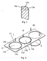
- FIG 3 is shown by a detailed view of the partially rounded throttle edge as the part surface 11a is divided into edge pieces 13a and 14a.
- the edge piece 13a is rounded and the edge piece 14a is not rounded.
- the partial surface 11b is subdivided point-symmetrically with respect to the partial surface 11a into a rounded edge piece 13b and a non-rounded edge piece 14b. This ensures that, taking into account manufacturing tolerances and thermal expansion effects, the rounded edge pieces 13a and 13b bear against the air duct wall 9 without tilting in the closed position of the throttle valve 4.
- the non-rounded edge pieces 14a and 14b increase the flow resistance of the leakage air.
- the representation of an advantageous method for producing the throttle in Fig. 4 shows as in a first step I, the partial surfaces 11a and 11b of the throttle valve 4 are punched. However, the transition surfaces 12a and 12b are not yet punched.
- a second step II the rounded Randstükke 13a and 13b are generated.
- the embossing is carried out by a single work step, without it being necessary, for example, to do so.
- B. spend a further step for turning the sheet around.
- the throttle valve 4 is punched out. By this method is avoided, such as in DE 198 02 673 A1 the rounding is produced by milling.
Landscapes
- Engineering & Computer Science (AREA)
- Chemical & Material Sciences (AREA)
- Combustion & Propulsion (AREA)
- Mechanical Engineering (AREA)
- General Engineering & Computer Science (AREA)
- Lift Valve (AREA)
Description
- Die Erfindung betrifft eine Drosselklappenanordnung für Brennkraftmaschinen mit einem Gehäuse, das einen Luftkanal aufweist, in dem eine scheibenförmige Drosselklappe schwenkbar auf einer Antriebswelle gelagert ist, wobei die Drosselklappe mindestens eine Bohrung für ein Befestigungselement und eine zumindest teilweise gerundete Mantelfläche aufweist, die im geschlossenen Zustand an dem Gehäuse anliegt
- Eine derartige Drosselklappe ist beispielsweise in
DE 198 02 673 A1 offenbart und weist dort Maßnahmen auf, die eine Verringerung der Leckluft bewirken sollen. Diese bestehen aus einer umlaufend gerundeten Mantelfläche der Drosselklappe, die durch Fräsen erzielt wird. - Aus der
DE 197 14 717 A1 ist eine Drosselklappe bekannt, bei der die Mantelfläche verschiedene Geometrien aufweist, jedoch immer derart, dass die Mantelfläche über den gesamten Umfang gleich ausgebildet ist. - Diese Ausführungen lassen immer noch eine zu große Leckluft zu und sind im Herstellungsprozeß aufwendig und dadurch teuer.
- Aus der
GB 2 062 182 A - Es besteht daher Bedarf nach für die Großserienfertigung geeigneten Maßnahmen, mit denen eine Verringerung der Leckluft erreicht und gleichzeitig der bisherige Aufbau des Drosselklappenstutzens erhalten bleiben kann.
- 1. Diese Aufgabe wird bei einer gattungsgemäßen Drosselklappe dadurch gelöst, dass die Mantelfläche zwei Teilflächen und zwei Übergangsflächen aufweist,
- Die Erfindung basiert auf der Erkenntnis, dass die Formgebung der Drosselklappe an den für das verkantungsfreie Schließen der Drosselklappe irrelevanten Teil des Seitenrandes den Strömungswiderstand der Leckluft in Schließstellung der Drosselklappe vorteilhaft beeinflussen kann ohne dass im geöffneter Stellung der Drosselklappe ein zusätzlich Druckverlust auftritt.
- Indem auf die Rundung des der Anschlagfläche der Drosselklappe abgewandten Seitenrandes, wie dies beispielsweise bei
DE 198 02 673 A1 der Fall ist, verzichtet wird, wird die Strecke des engsten Querschnitts in Schließstellung der Drosselklappe, durch welche die Leckluft strömt, verlängert. Da sich die Stromlinien der Leckluft zum Mittelpunkt des Luftkanals hin in etwa dem Profil einer Laval-Düse annähern, das die Kante der nicht gerundeten Teilfläche tangiert, ergibt sich an der Leckstelle ein Totwassergebiet, das den kleinsten effektiv durchströmten hydraulischen Querschnitt deutlich verringert. Durch diese Erfindung werden somit die fluiddynamischen Staupunkte am Umfang der Drosselklappe stärker ausgeprägt, was den Strömungswiderstand der Drosselklappe in Schließstellung erhöht. Dies führt zu einer Verringerung des sich ergebenden Massenstroms der Leckluft. - Durch diese Erfindung ist es möglich geworden, das Verfahren zur Herstellung dieser Drosselklappe erheblich zu verbessern. Anstatt wie beispielsweise bei
DE 198 02 673 A1 die gerundeten Randstücke durch Fräsen herzustellen, kann die Rundung durch ein spanloses Umformfahren erfolgen. So kann, nachdem zunächst nur die Kontur der zu rundenden Teilflächen ausgestanzt wird, die Rundung beispielsweise durch Prägen erzeugt werden, ohne dass die zu fertigende Drosselklappe aus dem Blech, aus dem sie herausgestanzt wird, zuvor herausgelöst wird. Dadurch dass die Drosselklappe mit Hilfe der noch nicht ausgestanzten Übergangsflächen mit dem Blech fixiert ist, ist es zusätzlich möglich, die Bohrungen in der Drosselklappe in einen weiteren Fertigungsschritt auszustanzen, was dazu führt, dass die Position der Bohrungen in Relation zur Mantelfläche der Drosselklappe sehr viel genauer angeordnet wird. - Im folgenden ist die Erfindung an einer vorteilhaften Ausführung beschrieben, wobei
- in
Fig.1 die Drosselklappenanordnung in einer Schnittansicht, - in
Fig. 2 die Drosselklappe in einer Draufsicht, - in
Fig. 3 eine Detailansicht des teilweise gerundeten Drosselklappenrandes und - in
Fig. 4 eine Darstellung eines vorteilhaften Verfahrens zur Herstellung der Drosselklappe - In
Fig. 1 ist eine Drosselklappenanordnung 1 mit einem Gehäuse 2, das einen Luftkanal 3 bildet, in dem eine scheibenförmige Drosselklappe 4 mit einer Bohrung 5 für ein Befestigungselement 6 auf einer Antriebswelle 7 befestigt ist, schematisch dargestellt. In ihr ist deutlich zu sehen, dass in Schließstellung eine Mantelfläche 8 der Drosselklappe 4 an einer Luftkanalwand 9 anliegt, wodurch der Luftkanal 3 abgedichtet wird. -
Fig. 2 zeigt die Draufsicht der Drosselklappe 4 mit einer Drehachse 10. Zur Mantelfläche 8 der Drosselklappe 4 gehören zwei Teilflächen 11a und 11b und zwei Übergangsflächen 12a und 12b, die jeweils punktsymmetrisch angeordnet sind. Es ist inFig. 2 deutlich zu erkennen, dass die Übergangsflächen 12a und 12b im Verhältnis zu den Teilflächen 11a und 11b klein sind. Die Genauigkeit der Position der Bohrungen 5a und 5b in Relation zu den Teilflächen 11a und 11b wird verbessert, wenn sie ausgestanzt werden, während die Übergangsflächen 12a und 12b noch mit dem Blech, aus dem die Drosselklappe 4 ausgestanzt wird, verbunden sind. - In
Fig.3 ist durch eine Detailansicht des teilweise gerundeten Drosselklappenrandes dargestellt wie die Teilfläche 11a in Randstücke 13a und 14a unterteilt ist. Dabei ist das Randstück 13a gerundet und das Randstück 14a nicht gerundet. Analog dazu ist die Teilfläche 11b punktsymmetrisch zur Teilfläche 11a in ein gerundetes Randstück 13b und ein nicht gerundetes Randstück 14b unterteilt. Somit ist sichergestellt, dass unter Berücksichtigung von Fertigungstoleranzen und Wärmedehnungseffekten die gerundeten Randstücke 13a und 13b in Schließstellung der Drosselklappe 4 verkantungsfrei an der Luftkanalwand 9 anliegen. Gleichzeitig erhöhen die nicht gerundeten Randstücke 14a und 14b den Strömungswiderstand der Leckluft. - Die Darstellung eines vorteilhaften Verfahrens zur Herstellung der Drosselklappe in
Fig. 4 zeigt wie in einem ersten Schritt I die Teilflächen 11a und 11b der Drosselklappe 4 gestanzt werden. Die Übergangsflächen 12a und 12b werden allerdings noch nicht gestanzt. In einem zweiten Schritt II werden die abgerundeten Randstükke 13a und 13b erzeugt. Dadurch dass beim Prägen von zwei Seiten gleichzeitig eine Kraft aufgebracht werden kann, wird das Prägen durch einen einzigen Arbeitsschritt durchgeführt, ohne dass es notwendig ist z. B. für das Herumdrehen des Blechs einen weiteren Arbeitsschritt aufzuwenden. In einem letzten Schritt III wird die Drosselklappe 4 ausgestanzt. Durch dieses Verfahren wird vermieden, dass wie beispielsweise beiDE 198 02 673 A1 die Rundung durch Fräsen erzeugt wird.
Claims (2)
- Drosselklappenanordnung (1) für Brennkraftmaschinen mit einem Gehäuse (2), das einen Luftkanal (3) aufweist, in dem eine scheibenförmige Drosselklappe (4) schwenkbar auf einer Antriebswelle (7) gelagert ist, wobei die Drosselklappe (4) mindestens eine Bohrung (5) für ein Befestigungselement (6) und eine zumindest teilweise gerundete Mantelfläche (8) aufweist, die im geschlossenen Zustand an dem Gehäuse (2) anliegt, dadurch gekennzeichnet, dass die Mantelfläche (8) zwei Teilflächen (11a und 11 b) und zwei Übergangsflächen (12a und 12b) aufweist, wobei die Teilflächen (11a und 11b) punktsymmetrisch zur Drehachse (10) der Drosselklappe angeordnet sind und die Übergangsflächen (12a und 12b) im Bereich der Antriebswelle (7) angeordnet sind und im Verhältnis zu den Teilflächen (11a,11b) klein sind, wobei die Teilflächen (11a und 11 b) zwei Randstücke (13 und 14) aufweisen, derart, dass das in Schließstellung der Drosselklappe (4) zur Luftkanalwand (9) gerichtete Randstück (13a,13b) abgerundet ist und das andere Randstück (14a,14b) nicht abgerundet ist.
- Verfahren zur Herstellung der Drosselklappe nach Anspruch 1 dadurch gekennzeichnet, dass in einem ersten Schritt (I) eine Kontur (15) der Drosselklappe (4) mit Ausnahme der Übergangsflächen (12a und 12b) gestanzt wird, wobei die Kontur (15) die zwei Teilflächen (11a und 11 b) umfasst, in einem zweiten Schritt (II) die abgerundeten Randstücke (13a und 13b) durch ein spanloses Umformverfahren, insbesondere Prägen, erzeugt werden, wobei ein nach oben gerichtetes Randstück (13a) und ein nach unten gerichtetes Randstück (13b) verformt wird und in einem letzten Schritt (III) die Drosselklappe (4) ausgestanzt wird, derart, dass die Übergangsflächen (12a) und (12b) ausgestanzt werden, wobei die Übergangsflächen im Bereich der Antriebswelle vorgesehen sind und im Verhältniss zu den Teilflächen klein sind.
Applications Claiming Priority (2)
| Application Number | Priority Date | Filing Date | Title |
|---|---|---|---|
| DE10150516 | 2001-10-12 | ||
| DE2001150516 DE10150516A1 (de) | 2001-10-12 | 2001-10-12 | Drosselklappenanordnung für Brennkraftmaschinen |
Publications (3)
| Publication Number | Publication Date |
|---|---|
| EP1302641A2 EP1302641A2 (de) | 2003-04-16 |
| EP1302641A3 EP1302641A3 (de) | 2004-06-30 |
| EP1302641B1 true EP1302641B1 (de) | 2008-12-10 |
Family
ID=7702357
Family Applications (1)
| Application Number | Title | Priority Date | Filing Date |
|---|---|---|---|
| EP02016455A Expired - Lifetime EP1302641B1 (de) | 2001-10-12 | 2002-07-23 | Drosselklappenanordnung für Brennkraftmaschinen |
Country Status (3)
| Country | Link |
|---|---|
| EP (1) | EP1302641B1 (de) |
| DE (2) | DE10150516A1 (de) |
| ES (1) | ES2314013T3 (de) |
Families Citing this family (2)
| Publication number | Priority date | Publication date | Assignee | Title |
|---|---|---|---|---|
| DE10328246B4 (de) * | 2003-06-24 | 2007-04-26 | Pierburg Gmbh | Kraftfahrzeugventil |
| DE102007013782B3 (de) * | 2007-03-22 | 2008-09-25 | Pierburg Gmbh | Verfahren zur Herstellung einer Klappenvorrichtung für Verbrennungskraftmaschinen sowie derartige Klappenvorrichtung |
Citations (3)
| Publication number | Priority date | Publication date | Assignee | Title |
|---|---|---|---|---|
| GB119180A (en) * | 1918-02-05 | 1918-09-26 | Andrew Eadie Cook | Carburettor for Internal Combustion Engines. |
| GB2062182A (en) * | 1979-10-15 | 1981-05-20 | Nissan Motor | Air flow detection arrangement |
| DE19714717A1 (de) * | 1996-10-01 | 1998-04-09 | Mitsubishi Electric Corp | Steuerventilvorrichtung |
Family Cites Families (5)
| Publication number | Priority date | Publication date | Assignee | Title |
|---|---|---|---|---|
| DE1600880A1 (de) * | 1951-01-28 | 1971-09-16 | Pierburg Kg A | Drosselklappe |
| US3596493A (en) * | 1967-09-15 | 1971-08-03 | Maurice Lachaussee | Stamping process for metal objects |
| DK11278A (da) * | 1978-01-10 | 1979-07-11 | Knudsen A S | Oprivningslukke |
| FR2674600B1 (fr) * | 1991-03-27 | 1993-07-09 | Solex | Procede de fabrication de papillon d'etranglement utilisable dans une installation d'alimentation en combustible. |
| DE19802673A1 (de) | 1998-01-24 | 1999-07-29 | Pierburg Ag | Drosselklappenstutzen für Brennkraftmaschinen |
-
2001
- 2001-10-12 DE DE2001150516 patent/DE10150516A1/de not_active Withdrawn
-
2002
- 2002-07-23 DE DE50213097T patent/DE50213097D1/de not_active Expired - Lifetime
- 2002-07-23 EP EP02016455A patent/EP1302641B1/de not_active Expired - Lifetime
- 2002-07-23 ES ES02016455T patent/ES2314013T3/es not_active Expired - Lifetime
Patent Citations (3)
| Publication number | Priority date | Publication date | Assignee | Title |
|---|---|---|---|---|
| GB119180A (en) * | 1918-02-05 | 1918-09-26 | Andrew Eadie Cook | Carburettor for Internal Combustion Engines. |
| GB2062182A (en) * | 1979-10-15 | 1981-05-20 | Nissan Motor | Air flow detection arrangement |
| DE19714717A1 (de) * | 1996-10-01 | 1998-04-09 | Mitsubishi Electric Corp | Steuerventilvorrichtung |
Also Published As
| Publication number | Publication date |
|---|---|
| ES2314013T3 (es) | 2009-03-16 |
| EP1302641A2 (de) | 2003-04-16 |
| DE50213097D1 (de) | 2009-01-22 |
| EP1302641A3 (de) | 2004-06-30 |
| DE10150516A1 (de) | 2003-04-17 |
Similar Documents
| Publication | Publication Date | Title |
|---|---|---|
| EP1198672B1 (de) | Kraftstoffeinspritzventil für brennkraftmaschinen | |
| DE112020001509T5 (de) | Ventilsitzeinsatz mit doppelter krone mit sitzfläche aus aufschweissmaterial | |
| EP2480783B1 (de) | Kraftstoff-einspritzventil für eine brennkraftmaschine | |
| EP1831537B1 (de) | Injektor eines kraftstoffeinspritzsystems einer brennkraftmaschine | |
| EP1689999A1 (de) | Kraftstoff-einspritzvorrichtung, insbesondere für eine brennkraftmaschine mit kraftstoff-direkteinspritzung, sowie verfahren zu ihrer herstellung | |
| DE102008056245A1 (de) | Thermostatventil | |
| DE602004008292T2 (de) | Kraftstoffeinspritzventil mit einer lochscheibe und verfahren zur herstellung der lochscheibe durch ausschaben und stanzen | |
| DE3827324C2 (de) | ||
| DE19751293A1 (de) | Einschichtige oder mehrschichtige Metallzylinderkopfdichtung und Verfahren zu ihrer Herstellung | |
| EP2079911B1 (de) | Drosselklappenstutzen | |
| EP1828593A1 (de) | Kraftstoffeinspritzventil f]r eine brennkraftmaschine | |
| DE4201450C1 (de) | ||
| EP1302641A2 (de) | Drosselklappenanordnung für Brennkraftmaschinen | |
| DE19907678A1 (de) | Verfahren zur Herstellung von Steuerkanten an einem Ventil, vorzugsweise an einem Ventil für einen Kraftstoff-Injektor einer Verbrennungsmaschine sowie Kraftstoff-Injektor mit einem solchen Ventil | |
| DE60314226T2 (de) | Sprühmusterelement und Kraftstoffeinspritzventil mit demselben | |
| DE19956929B4 (de) | Öldruck-Regelventil | |
| EP1601869B1 (de) | Ventil mit federelement für einen kraftstoffinjektor | |
| EP1217270B1 (de) | Hubventil | |
| EP1421262B1 (de) | Ventilmechanismus mit einem variablen ventilöffnungsquerschnitt | |
| DE102007015873A1 (de) | Drosselklappenanordnung | |
| DE102006017213A1 (de) | Metallische Flachdichtung mit zerbrechlichen Verbindungsabschnitten | |
| EP1340907A2 (de) | Verfahren zur Herstellung eines Kraftstoffeinspritzventils | |
| EP0286810B1 (de) | Verfahren zum Herstellen eines Ventils, insbesondere eines thermostatischen Ventils | |
| EP1256708A2 (de) | Kraftstoff-Einspritzvorrichtung für eine Brennkraftmaschine | |
| EP2468432A1 (de) | Verfahren zum Herstellen einer Schaltkulisse, Schaltkulisse sowie Verbrennungsmotor |
Legal Events
| Date | Code | Title | Description |
|---|---|---|---|
| PUAI | Public reference made under article 153(3) epc to a published international application that has entered the european phase |
Free format text: ORIGINAL CODE: 0009012 |
|
| 17P | Request for examination filed |
Effective date: 20020723 |
|
| AK | Designated contracting states |
Designated state(s): AT BE BG CH CY CZ DE DK EE ES FI FR GB GR IE IT LI LU MC NL PT SE SK TR |
|
| AX | Request for extension of the european patent |
Extension state: AL LT LV MK RO SI |
|
| PUAL | Search report despatched |
Free format text: ORIGINAL CODE: 0009013 |
|
| AK | Designated contracting states |
Kind code of ref document: A3 Designated state(s): AT BE BG CH CY CZ DE DK EE ES FI FR GB GR IE IT LI LU MC NL PT SE SK TR |
|
| AX | Request for extension of the european patent |
Extension state: AL LT LV MK RO SI |
|
| RIC1 | Information provided on ipc code assigned before grant |
Ipc: 7F 02D 9/10 A Ipc: 7F 16K 1/226 B |
|
| AKX | Designation fees paid |
Designated state(s): DE ES FR GB IT |
|
| 17Q | First examination report despatched |
Effective date: 20070920 |
|
| GRAP | Despatch of communication of intention to grant a patent |
Free format text: ORIGINAL CODE: EPIDOSNIGR1 |
|
| GRAS | Grant fee paid |
Free format text: ORIGINAL CODE: EPIDOSNIGR3 |
|
| GRAS | Grant fee paid |
Free format text: ORIGINAL CODE: EPIDOSNIGR3 |
|
| GRAA | (expected) grant |
Free format text: ORIGINAL CODE: 0009210 |
|
| AK | Designated contracting states |
Kind code of ref document: B1 Designated state(s): DE ES FR GB IT |
|
| REG | Reference to a national code |
Ref country code: GB Ref legal event code: FG4D Free format text: NOT ENGLISH |
|
| REF | Corresponds to: |
Ref document number: 50213097 Country of ref document: DE Date of ref document: 20090122 Kind code of ref document: P |
|
| REG | Reference to a national code |
Ref country code: ES Ref legal event code: FG2A Ref document number: 2314013 Country of ref document: ES Kind code of ref document: T3 |
|
| PLBE | No opposition filed within time limit |
Free format text: ORIGINAL CODE: 0009261 |
|
| STAA | Information on the status of an ep patent application or granted ep patent |
Free format text: STATUS: NO OPPOSITION FILED WITHIN TIME LIMIT |
|
| 26N | No opposition filed |
Effective date: 20090911 |
|
| GBPC | Gb: european patent ceased through non-payment of renewal fee |
Effective date: 20090723 |
|
| PG25 | Lapsed in a contracting state [announced via postgrant information from national office to epo] |
Ref country code: GB Free format text: LAPSE BECAUSE OF NON-PAYMENT OF DUE FEES Effective date: 20090723 |
|
| REG | Reference to a national code |
Ref country code: ES Ref legal event code: FD2A Effective date: 20090724 |
|
| PG25 | Lapsed in a contracting state [announced via postgrant information from national office to epo] |
Ref country code: ES Free format text: LAPSE BECAUSE OF NON-PAYMENT OF DUE FEES Effective date: 20090724 |
|
| PGFP | Annual fee paid to national office [announced via postgrant information from national office to epo] |
Ref country code: FR Payment date: 20100802 Year of fee payment: 9 Ref country code: IT Payment date: 20100729 Year of fee payment: 9 |
|
| REG | Reference to a national code |
Ref country code: FR Ref legal event code: ST Effective date: 20120330 |
|
| PG25 | Lapsed in a contracting state [announced via postgrant information from national office to epo] |
Ref country code: FR Free format text: LAPSE BECAUSE OF NON-PAYMENT OF DUE FEES Effective date: 20110801 |
|
| PG25 | Lapsed in a contracting state [announced via postgrant information from national office to epo] |
Ref country code: IT Free format text: LAPSE BECAUSE OF NON-PAYMENT OF DUE FEES Effective date: 20110723 |
|
| PGFP | Annual fee paid to national office [announced via postgrant information from national office to epo] |
Ref country code: DE Payment date: 20160721 Year of fee payment: 15 |
|
| REG | Reference to a national code |
Ref country code: DE Ref legal event code: R119 Ref document number: 50213097 Country of ref document: DE |
|
| PG25 | Lapsed in a contracting state [announced via postgrant information from national office to epo] |
Ref country code: DE Free format text: LAPSE BECAUSE OF NON-PAYMENT OF DUE FEES Effective date: 20180201 |