EP1302336B1 - Rolling bearing unit - Google Patents
Rolling bearing unit Download PDFInfo
- Publication number
- EP1302336B1 EP1302336B1 EP02022783A EP02022783A EP1302336B1 EP 1302336 B1 EP1302336 B1 EP 1302336B1 EP 02022783 A EP02022783 A EP 02022783A EP 02022783 A EP02022783 A EP 02022783A EP 1302336 B1 EP1302336 B1 EP 1302336B1
- Authority
- EP
- European Patent Office
- Prior art keywords
- inner ring
- rolling bearing
- edge
- bearing unit
- surface layer
- Prior art date
- Legal status (The legal status is an assumption and is not a legal conclusion. Google has not performed a legal analysis and makes no representation as to the accuracy of the status listed.)
- Expired - Lifetime
Links
Images

Classifications
-
- F—MECHANICAL ENGINEERING; LIGHTING; HEATING; WEAPONS; BLASTING
- F16—ENGINEERING ELEMENTS AND UNITS; GENERAL MEASURES FOR PRODUCING AND MAINTAINING EFFECTIVE FUNCTIONING OF MACHINES OR INSTALLATIONS; THERMAL INSULATION IN GENERAL
- F16C—SHAFTS; FLEXIBLE SHAFTS; ELEMENTS OR CRANKSHAFT MECHANISMS; ROTARY BODIES OTHER THAN GEARING ELEMENTS; BEARINGS
- F16C43/00—Assembling bearings
- F16C43/04—Assembling rolling-contact bearings
-
- B—PERFORMING OPERATIONS; TRANSPORTING
- B60—VEHICLES IN GENERAL
- B60B—VEHICLE WHEELS; CASTORS; AXLES FOR WHEELS OR CASTORS; INCREASING WHEEL ADHESION
- B60B27/00—Hubs
-
- B—PERFORMING OPERATIONS; TRANSPORTING
- B60—VEHICLES IN GENERAL
- B60B—VEHICLE WHEELS; CASTORS; AXLES FOR WHEELS OR CASTORS; INCREASING WHEEL ADHESION
- B60B27/00—Hubs
- B60B27/0005—Hubs with ball bearings
-
- B—PERFORMING OPERATIONS; TRANSPORTING
- B60—VEHICLES IN GENERAL
- B60B—VEHICLE WHEELS; CASTORS; AXLES FOR WHEELS OR CASTORS; INCREASING WHEEL ADHESION
- B60B27/00—Hubs
- B60B27/0078—Hubs characterised by the fixation of bearings
- B60B27/0084—Hubs characterised by the fixation of bearings caulking to fix inner race
-
- B—PERFORMING OPERATIONS; TRANSPORTING
- B60—VEHICLES IN GENERAL
- B60B—VEHICLE WHEELS; CASTORS; AXLES FOR WHEELS OR CASTORS; INCREASING WHEEL ADHESION
- B60B27/00—Hubs
- B60B27/0094—Hubs one or more of the bearing races are formed by the hub
-
- F—MECHANICAL ENGINEERING; LIGHTING; HEATING; WEAPONS; BLASTING
- F16—ENGINEERING ELEMENTS AND UNITS; GENERAL MEASURES FOR PRODUCING AND MAINTAINING EFFECTIVE FUNCTIONING OF MACHINES OR INSTALLATIONS; THERMAL INSULATION IN GENERAL
- F16C—SHAFTS; FLEXIBLE SHAFTS; ELEMENTS OR CRANKSHAFT MECHANISMS; ROTARY BODIES OTHER THAN GEARING ELEMENTS; BEARINGS
- F16C19/00—Bearings with rolling contact, for exclusively rotary movement
- F16C19/02—Bearings with rolling contact, for exclusively rotary movement with bearing balls essentially of the same size in one or more circular rows
- F16C19/14—Bearings with rolling contact, for exclusively rotary movement with bearing balls essentially of the same size in one or more circular rows for both radial and axial load
- F16C19/18—Bearings with rolling contact, for exclusively rotary movement with bearing balls essentially of the same size in one or more circular rows for both radial and axial load with two or more rows of balls
- F16C19/181—Bearings with rolling contact, for exclusively rotary movement with bearing balls essentially of the same size in one or more circular rows for both radial and axial load with two or more rows of balls with angular contact
- F16C19/183—Bearings with rolling contact, for exclusively rotary movement with bearing balls essentially of the same size in one or more circular rows for both radial and axial load with two or more rows of balls with angular contact with two rows at opposite angles
- F16C19/184—Bearings with rolling contact, for exclusively rotary movement with bearing balls essentially of the same size in one or more circular rows for both radial and axial load with two or more rows of balls with angular contact with two rows at opposite angles in O-arrangement
- F16C19/186—Bearings with rolling contact, for exclusively rotary movement with bearing balls essentially of the same size in one or more circular rows for both radial and axial load with two or more rows of balls with angular contact with two rows at opposite angles in O-arrangement with three raceways provided integrally on parts other than race rings, e.g. third generation hubs
-
- F—MECHANICAL ENGINEERING; LIGHTING; HEATING; WEAPONS; BLASTING
- F16—ENGINEERING ELEMENTS AND UNITS; GENERAL MEASURES FOR PRODUCING AND MAINTAINING EFFECTIVE FUNCTIONING OF MACHINES OR INSTALLATIONS; THERMAL INSULATION IN GENERAL
- F16C—SHAFTS; FLEXIBLE SHAFTS; ELEMENTS OR CRANKSHAFT MECHANISMS; ROTARY BODIES OTHER THAN GEARING ELEMENTS; BEARINGS
- F16C2326/00—Articles relating to transporting
- F16C2326/01—Parts of vehicles in general
- F16C2326/02—Wheel hubs or castors
-
- Y—GENERAL TAGGING OF NEW TECHNOLOGICAL DEVELOPMENTS; GENERAL TAGGING OF CROSS-SECTIONAL TECHNOLOGIES SPANNING OVER SEVERAL SECTIONS OF THE IPC; TECHNICAL SUBJECTS COVERED BY FORMER USPC CROSS-REFERENCE ART COLLECTIONS [XRACs] AND DIGESTS
- Y10—TECHNICAL SUBJECTS COVERED BY FORMER USPC
- Y10T—TECHNICAL SUBJECTS COVERED BY FORMER US CLASSIFICATION
- Y10T29/00—Metal working
- Y10T29/49—Method of mechanical manufacture
- Y10T29/49636—Process for making bearing or component thereof
- Y10T29/49707—Bearing surface treatment
Definitions
- This invention relates to a rolling bearing unit having a rolling bearing attached to the outer periphery of a shaft body such as a vehicle-use hub unit.
- Document US-A-5822 859 which represents the closest prior art, discloses an improved method for retaining a separable bearing race to a inner bearing member by rolling over a deformable lip of the inner bearing member into a race abutting bedt.
- the outer edge and inner surface of the separable race are cut away partially by a shallow, continuous, conical relieved portion with sufficient length and radial thickness to accommodate the degree of material swelling just inside of the race that results from the lip deformation process.
- the rolling bearing unit disclosed by this document comprises the features of the preamble of claim 1.
- the vehicle-use hub unit in general, has a hub wheel and a double row rolling bearing.
- the rolling bearing is mounted on the outer periphery of the shaft body of a hub wheel so as not to slip off the shaft body.
- the shaft body of the hub wheel has on its free end side a cylindrical portion used for preventing the bearing from slipping off the shaft body.
- the cylindrical portion is bent and deformed outward in a radial direction using a caulking jig to be caulked onto an axial outer end face of an inner ring of the bearing. Thereby the cylindrical portion forms a caulking portion.
- the caulking portion prevents the bearing from slipping off the hub wheel.
- a pre-load is applied from the caulking portion to the inner ring of the bearing.
- Carbon steel is used as the material of the inner ring of the bearing.
- the inner ring is heat-treated to increase the strength of a raceway surface thereof.
- season cracking When the rolling bearing unit is left for the purpose of storage or the like with the inner ring caulked onto the shaft body of the hub wheel, a phenomenon in which the inner ring is cracked and broken (hereinafter, referred to as season cracking may be generated.
- the surface layer, which causes season cracking is removed from the edge of the inner ring. Therefore, the influence of a volume increase in the transformation of retained austenite into martensite, is reduced. As a result, the generation of the season cracking on the edge of the inner ring due to an increase in a tensile strength is prevented.
- the surface layer is removed from edge of the inner ring by polishing or turning. More preferably, an amount of the retained austenite existing in the edge of the inner ring is set between 3% or more and 20% or less by removing the surface layer.
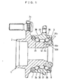
- Fig. 1 illustrates a rolling bearing unit comprising a vehicle-use hub unit for a driving wheel according to a preferred embodiment of the invention.
- a hub wheel 1 on which a wheel is mounted has a shaft body 2 as a rotatable shaft.
- a double row rolling bearing 3, which is specifically an angular ball bearing as one example of rolling bearings, is pressed and fitted onto the outer peripheral surface of the shaft body 2 from the vehicle inner side.
- the rolling bearing 3 has an inner ring 32.
- the inner ring 32 is attached to an annular groove 2a in the outer peripheral surface of the vehicle inner side of the shaft body 2.
- the inner ring 32 has an inner ring raceway 32d
- the shaft body 2 has an inner ring raceway 2b on the outer peripheral surface in the middle in an axial direction thereof.
- the inner ring raceway 2b constitutes a pair of inner ring raceways in the axial direction together with the inner ring raceway 32d of the inner ring 32.
- the shaft body 2 has an outward radial flange 2c on the outer peripheral surface of the vehicle outer side thereof.
- a tire wheel and a brake disk, not shown, are attached to a side of the vehicle outer side of the flange 2c. Furthermore, the rolling bearing 3 has an outer ring 33.
- the outer ring 33 is fixed to a vehicle body through a steering knuckle, not shown, and is provided with outer ring raceways 38 and 39 in two rows in the axial direction on the inner peripheral surface thereof.
- the outer ring 33 is situated coaxially on the outside in the radial direction with respect to the inner ring 32.
- the rolling bearing 3 includes; balls 34 and 35 in two rows in the axial direction interposed between the inner ring raceways 32d and 2b and outer ring raceways 38 and 39; cages 36 and 37 in two rows in the axial direction which hold the balls 34 and 35; and seal rings 7 and 8 for sealing both ends in the axial direction of the rolling bearing 3.
- a shaft end of the vehicle inner side of the shaft body 2 is bent and deformed outward in a radial direction and is caulked onto an outer end face 32a on the vehicle inner side of the inner ring 32, thereby forming a caulking portion 4.
- the caulking portion 4 as a fastening member applies a appropriate pre-load to the balls 34 and 35 and prevents the rolling bearing 3 from slipping from the shaft body 2.
- carbon steel such as high carbon chromium steel (Japanese Industrial Standards SUJ2, bearing steel) or carbon steels for machine structural use (Japanese Industrial Standards S55C) is used for the material of the inner ring 32.
- the inner ring 32 is heat treated in a process for manufacturing the inner ring 32.
- the heat treatment is carried out in a slight carburizing atmosphere in order to prevent decarburization.
- the heat treatment is carried out in a carbonitriding atmosphere in which a small amount of NH 3 (ammonia gas) is added to an atmospheric gas.
- Numeral 32 denotes an inner ring and numeral 2 denotes a shaft body of a hub wheel.
- the end of the shaft body 2 is caulked onto an outer end face 32a on the end in the axial direction of the inner ring 32, thereby forming a caulking portion 4.
- a tensile stress in a circumferential direction is applied from the caulking portion 4 to a portion of the inner ring 32 in the vicinity of the caulking portion 4. Since the outer end face 32a of the inner ring 32 is held by the caulking portion 4, the tensile stress thereof converges on an outer diameter side edge 32b of the inner ring 32.
- a surface layer L having an amount of retained austenite larger than other portion is formed on the surface of the inner ring 32 as shown in Fig. 4 .
- An outer diameter side edge 32b of the outer end face 32a of the inner ring 32 is constituted by the outer end face 32a of the inner ring 32 and an outer peripheral surface 32c in a shoulder portion of the inner ring.
- the retained austenite amount becomes larger than that of the other surface layer due to heating and carbon diffusion from the outer end face 32a and the outer diameter surface 32c in the inner ring 32 during the heat treatment of the inner ring 32.
- the retained austenite in the surface layer L is transformed into martensite, so that the volume of the surface layer L is increased.
- the increase in the volume of the surface layer L by the martensite results in an increase in a tensile stress .
- season cracking may be caused over the diameter side edge 32b of the inner ring 32.
- the retained austenite amount in the outer diameter side edge 32b of the inner ring 32 causes the generation of the season cracking phenomenon.
- this invention proposes a rolling bearing unit capable of preventing the season cracking phenomenon by decreasing the retained austenite amount in the outer diameter side edge 32b of the inner ring 32.
- the surface layer L in the outer diameter side edge 32b of the inner ring 32 is removed until a predetermined depth by polishing or turning, thereby decreasing the retained austenite amount in the outer diameter side edge 32b.
- the surface layer L is removed such that the retained austenite amount becomes between 3% or more and 20% or less in the range a in which at least tensile stress converges, thereby reducing the percentage of generation of the season cracking in the inner ring 32.
- a concrete range a is determined as follows.
- the range a in a radius r, in which the surface layer is removed from the edge 32b, satisfies the following expression: ⁇ B - ⁇ A / 2 ⁇ r ⁇ D wherein ⁇ A represents an outer diameter of the caulking portion 4, ⁇ B represents an outer diameter of the outer peripheral surface 32c in the shoulder portion of the inner ring 32, r represents a radius from the edge 32b of the inner ring 32 in the vicinity of the caulking portion 4, and D(mm) represents a numeric value which is almost equal to the thickness of the surface layer in which an amount of retained austenite which generates on the surface of the inner ring 32 is much more than that of other portions of the inner ring (for example, 20% or more).
- the thickness of the surface layer is preferably 0.5 mm.
- retained austenite amount on the edge 32b is between 3% or more and 20% or less, preferably between 5% or more and 15% or less, more preferably between 5% or more and 10% or less.
- the season cracking was not generated after the passage of the days.
- the retained austenite amount was 23%, the season cracking was generated on a tenth day.
- the retained austenite amount was 30%, the season cracking was generated on a seventh day.
- the retained austenite amount is set between 3% or more and 20% or less within the range of the radius r satisfying the expression from the edge 32b of the inner ring 32 so that the influence of a volume dilatation can be reduced in the transformation of the retained austenite into martensite.
- the season cracking from being generated on the edge 32b of the inner ring 32 due to an increase in a tensile stress caused by the caulking portion 4. Consequently, the reliability of the bearing can be enhanced.
- the invention is not restricted to the embodiment in which the edge 32b of the inner ring 32 is subjected to the polishing or the turning to set the retained austenite amount in the edge 32b to be between 3% or more and 20% or less but the retained austenite amount in the edge 32b may be set between 3% or more and 20% or less by the optimization of heat-treating conditions in the process for manufacturing the inner ring 32.
- Conventional heat-treating conditions are as follows. More specifically, the inner ring 32 is put in a heat treat furnace. At this time, the internal temperature of the heat treating furnace is set to 850°C to 930°C. The heat treating time for the inner ring 32 is set to five hours.
- a carbon concentration C ⁇ P (Carbon ⁇ Potential) in the heat treat furnace is set to 1.1 to 1.4%, and an ammonia concentration is set to 5.51 x 10 -5 m 3 /sec (7 CFH) to 8.65 x 10 -5 m 3 /sec (11 CFH).
- the CFH represents ft 3 /H (cubic foot per hour.
- the internal temperature of the heat treat furnace is dropped to 800°C to 830°C and the temperature dropping state is kept for 30 minutes.
- the inner ring 32 is taken out of the heat treat furnace and is then thrown into the oil kept at temperatures of 60°C to 100°C to be quenched (oil cooling) .
- the inner ring 32 is tempered again for two hours in a heat treat furnace having an internal temperature of 160°C to 200°C. Subsequently, the inner ring 32 is taken out of the heat treating furnace and is air cooled.
- the conventional heat-treating conditions for the inner ring 32 are improved. More specifically, the inner ring 32 is put in the heat treat furnace. At this time, the internal temperature of the heat treating furnace is set to 850°C to 930°C. The heat treating time of the inner ring 32 is set to five hours. A carbon concentration C ⁇ P in the heat treating furnace is set to 0.9 to 1.1%, and an ammonia concentration is set to 4 to 7 CFH. Then, the internal temperature of the heat treat furnace is dropped to 800°C to 830°C. The temperature dropping state is held for 30 minutes. Thereafter the inner ring 32 is then taken out of the heat treat furnace and is thereafter put into oil kept at temperatures 60°C to 100°C to be quenched (oil cooling). After the oil cooling, the inner ring 32 is tempered again for two hours in a heat treat furnace having an internal temperature of 160°C to 200°C. Subsequently, the inner ring 32 is taken out of the heat treating furnace and is air cooled.
- the carbon concentration and the ammonia concentration in the heat-treating conditions are improved so that the retained austenite amount in the edge 32b can be set between 3% or more and 20% or less without polishing or turning the edge 32b of the inner ring 32.
- the invention is not restricted to the inner ring 32 having the structure described in the embodiment.
- a step 32e having a diameter reduced is provided on the vehicle inner side end of the shoulder portion of the inner ring 32, and the step 32e is set to be the installation space of a rotating speed sensor and the vehicle inner side end of the step 32e is set to be the edge 32b.
- the retained austenite amount within the range of the radius r satisfying the expression may be set between 3% or more and 20% or less in the edge 32b.
- a fastening member is not restricted to the caulking portion 4 in the embodiment but may be a nut screwed to the shaft body 2 and fastened to an outer end face in the axial direction of the inner ring 32.
- the shaft body 2 includes a fastening member which is fastened to the outer end face in the axial direction of the inner ring 32 and applies a tensile stress in the outer peripheral direction of the inner ring 32.
- the invention is not restricted to the hub unit comprising a combination of the hub wheel and the angular ball bearing in the embodiment but the hub wheel or the like may be set to be the shaft body and a rolling bearing such as an angular ball bearing may be applied to various rolling bearing units provided on the outer periphery of the shaft body.
Landscapes
- Engineering & Computer Science (AREA)
- Mechanical Engineering (AREA)
- General Engineering & Computer Science (AREA)
- Rolling Contact Bearings (AREA)
- Mounting Of Bearings Or Others (AREA)
- Support Of The Bearing (AREA)
Description
- This invention relates to a rolling bearing unit having a rolling bearing attached to the outer periphery of a shaft body such as a vehicle-use hub unit.
- Document
US-A-5822 859 , which represents the closest prior art, discloses an improved method for retaining a separable bearing race to a inner bearing member by rolling over a deformable lip of the inner bearing member into a race abutting bedt. The outer edge and inner surface of the separable race are cut away partially by a shallow, continuous, conical relieved portion with sufficient length and radial thickness to accommodate the degree of material swelling just inside of the race that results from the lip deformation process. The rolling bearing unit disclosed by this document comprises the features of the preamble ofclaim 1. - The vehicle-use hub unit, in general, has a hub wheel and a double row rolling bearing. The rolling bearing is mounted on the outer periphery of the shaft body of a hub wheel so as not to slip off the shaft body.
- The shaft body of the hub wheel has on its free end side a cylindrical portion used for preventing the bearing from slipping off the shaft body. The cylindrical portion is bent and deformed outward in a radial direction using a caulking jig to be caulked onto an axial outer end face of an inner ring of the bearing. Thereby the cylindrical portion forms a caulking portion. The caulking portion prevents the bearing from slipping off the hub wheel. At the same time, a pre-load is applied from the caulking portion to the inner ring of the bearing. Carbon steel is used as the material of the inner ring of the bearing.
- In order to enhance the life of the bearing, the inner ring is heat-treated to increase the strength of a raceway surface thereof.
- When the rolling bearing unit is left for the purpose of storage or the like with the inner ring caulked onto the shaft body of the hub wheel, a phenomenon in which the inner ring is cracked and broken (hereinafter, referred to as season cracking may be generated.
- Accordingly, it is a main object of the invention to provide a rolling bearing unit preventing the generation of season cracking in the edge of an inner ring of a rolling bearing.
- Other objects, features and advantages of the invention will be apparent from the following description.
- According to the invention, this is accomplished by providing a rolling bearing unit comprising the features of
claim 1. - According to the rolling bearing unit of the invention, the surface layer, which causes season cracking, is removed from the edge of the inner ring. Therefore, the influence of a volume increase in the transformation of retained austenite into martensite, is reduced. As a result, the generation of the season cracking on the edge of the inner ring due to an increase in a tensile strength is prevented.
- Preferably, the surface layer is removed from edge of the inner ring by polishing or turning. More preferably, an amount of the retained austenite existing in the edge of the inner ring is set between 3% or more and 20% or less by removing the surface layer.
- These and other objects as well as advantages of the invention will become clear by the following description of preferred embodiments of the invention with reference to the accompanying drawings, wherein:
-
Fig. 1 is a sectional view showing a rolling bearing unit comprising a hub unit for a driving wheel according to an embodiment of the invention; -
Fig. 2 is a sectional view showing an inner ring of the rolling bearing unit according to the embodiment of the invention; -
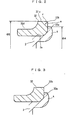
Fig. 3 is a sectional view showing an inner ring of a rolling bearing unit; -
Fig. 4 is a view illustrating a surface layer generated on the surface of the inner ring of the rolling bearing unit; and -
Fig. 5 is a sectional view showing an inner ring of a rolling bearing unit according to another embodiment of the invention. - In all these figures, like components are indicated by the same numerals.
- Referring now to the drawings,
Fig. 1 illustrates a rolling bearing unit comprising a vehicle-use hub unit for a driving wheel according to a preferred embodiment of the invention. Ahub wheel 1 on which a wheel is mounted has ashaft body 2 as a rotatable shaft. A double row rolling bearing 3, which is specifically an angular ball bearing as one example of rolling bearings, is pressed and fitted onto the outer peripheral surface of theshaft body 2 from the vehicle inner side. - The rolling
bearing 3 has aninner ring 32. Theinner ring 32 is attached to anannular groove 2a in the outer peripheral surface of the vehicle inner side of theshaft body 2. Theinner ring 32 has aninner ring raceway 32d, while theshaft body 2 has aninner ring raceway 2b on the outer peripheral surface in the middle in an axial direction thereof. Theinner ring raceway 2b constitutes a pair of inner ring raceways in the axial direction together with theinner ring raceway 32d of theinner ring 32. Moreover, theshaft body 2 has an outwardradial flange 2c on the outer peripheral surface of the vehicle outer side thereof. - A tire wheel and a brake disk, not shown, are attached to a side of the vehicle outer side of the
flange 2c.
Furthermore, the rollingbearing 3 has anouter ring 33. Theouter ring 33 is fixed to a vehicle body through a steering knuckle, not shown, and is provided withouter ring raceways - The
outer ring 33 is situated coaxially on the outside in the radial direction with respect to theinner ring 32. The rollingbearing 3 includes;balls inner ring raceways outer ring raceways cages balls seal rings bearing 3. - A shaft end of the vehicle inner side of the
shaft body 2 is bent and deformed outward in a radial direction and is caulked onto anouter end face 32a on the vehicle inner side of theinner ring 32, thereby forming acaulking portion 4. Thecaulking portion 4 as a fastening member applies a appropriate pre-load to theballs bearing 3 from slipping from theshaft body 2. - With reference to
Fig. 2 , carbon steel such as high carbon chromium steel (Japanese Industrial Standards SUJ2, bearing steel) or carbon steels for machine structural use (Japanese Industrial Standards S55C) is used for the material of theinner ring 32. - In order to increase the surface strength of the
raceway 32d of theinner ring 32 to enhance the life of the bearing, theinner ring 32 is heat treated in a process for manufacturing theinner ring 32. The heat treatment is carried out in a slight carburizing atmosphere in order to prevent decarburization. Or the heat treatment is carried out in a carbonitriding atmosphere in which a small amount of NH3 (ammonia gas) is added to an atmospheric gas. - As a result of an examination of season cracking, the following matters are considered. With reference to
Figs. 4 and 5 , description will be given to the phenomenon in which the season cracking is generated. Numeral 32 denotes an inner ring andnumeral 2 denotes a shaft body of a hub wheel. The end of theshaft body 2 is caulked onto anouter end face 32a on the end in the axial direction of theinner ring 32, thereby forming acaulking portion 4. A tensile stress in a circumferential direction is applied from thecaulking portion 4 to a portion of theinner ring 32 in the vicinity of thecaulking portion 4. Since theouter end face 32a of theinner ring 32 is held by thecaulking portion 4, the tensile stress thereof converges on an outerdiameter side edge 32b of theinner ring 32. - After the heat treatment of the inner ring, a surface layer L having an amount of retained austenite larger than other portion is formed on the surface of the
inner ring 32 as shown inFig. 4 . - An outer
diameter side edge 32b of theouter end face 32a of theinner ring 32 is constituted by theouter end face 32a of theinner ring 32 and an outerperipheral surface 32c in a shoulder portion of the inner ring. In the surface layer L of the outerdiameter side edge 32b, the retained austenite amount becomes larger than that of the other surface layer due to heating and carbon diffusion from theouter end face 32a and theouter diameter surface 32c in theinner ring 32 during the heat treatment of theinner ring 32. - After the heat treatment, the retained austenite in the surface layer L is transformed into martensite, so that the volume of the surface layer L is increased.
- Together with the tensile stress applied in the outer
diameter side edge 32b of theinner ring 32, the increase in the volume of the surface layer L by the martensite results in an increase in a tensile stress . As a result the season cracking may be caused over thediameter side edge 32b of theinner ring 32. - As described above, it is considered that the retained austenite amount in the outer
diameter side edge 32b of theinner ring 32 causes the generation of the season cracking phenomenon. - Thus, in order to prevent the season cracking, this invention proposes a rolling bearing unit capable of preventing the season cracking phenomenon by decreasing the retained austenite amount in the outer
diameter side edge 32b of theinner ring 32. - Hereinafter, description will be given of a method of decreasing the retained austenite amount in the outer
diameter side edge 32b of theinner ring 32. - According to a first method, in view of a point that the retained austenite amount in the surface layer L gradually decreases from the surface of the inner ring to the inside, the surface layer L in the outer
diameter side edge 32b of theinner ring 32 is removed until a predetermined depth by polishing or turning, thereby decreasing the retained austenite amount in the outerdiameter side edge 32b. - Accordingly, in the outer
diameter side edge 32b, the surface layer L is removed such that the retained austenite amount becomes between 3% or more and 20% or less in the range a in which at least tensile stress converges, thereby reducing the percentage of generation of the season cracking in theinner ring 32. - A concrete range a is determined as follows.
- The range a in a radius r, in which the surface layer is removed from the
edge 32b, satisfies the following expression:
caulking portion 4, φB represents an outer diameter of the outerperipheral surface 32c in the shoulder portion of theinner ring 32, r represents a radius from theedge 32b of theinner ring 32 in the vicinity of thecaulking portion 4, and D(mm) represents a numeric value which is almost equal to the thickness of the surface layer in which an amount of retained austenite which generates on the surface of theinner ring 32 is much more than that of other portions of the inner ring (for example, 20% or more). The thickness of the surface layer is preferably 0.5 mm. - By removing the surface layer present within the range satisfying the expression by the radius r from the
edge 32b of theinner ring 32, thus, retained austenite amount on theedge 32b is between 3% or more and 20% or less, preferably between 5% or more and 15% or less, more preferably between 5% or more and 10% or less. - When the retained austenite amount was equal to or less than 20%, the season cracking was not generated after the passage of the days. When the retained austenite amount was 23%, the season cracking was generated on a tenth day. When the retained austenite amount was 30%, the season cracking was generated on a seventh day.
- According to the rolling bearing unit thus constituted, the retained austenite amount is set between 3% or more and 20% or less within the range of the radius r satisfying the expression from the
edge 32b of theinner ring 32 so that the influence of a volume dilatation can be reduced in the transformation of the retained austenite into martensite. As a result, it is possible to prevent the season cracking from being generated on theedge 32b of theinner ring 32 due to an increase in a tensile stress caused by thecaulking portion 4. Consequently, the reliability of the bearing can be enhanced. - The invention is not restricted to the embodiment in which the
edge 32b of theinner ring 32 is subjected to the polishing or the turning to set the retained austenite amount in theedge 32b to be between 3% or more and 20% or less but the retained austenite amount in theedge 32b may be set between 3% or more and 20% or less by the optimization of heat-treating conditions in the process for manufacturing theinner ring 32. - Conventional heat-treating conditions are as follows. More specifically, the
inner ring 32 is put in a heat treat furnace. At this time, the internal temperature of the heat treating furnace is set to 850°C to 930°C. The heat treating time for theinner ring 32 is set to five hours. A carbon concentration C · P (Carbon · Potential) in the heat treat furnace is set to 1.1 to 1.4%, and an ammonia concentration is set to 5.51 x 10⁻⁵ m3/sec (7 CFH) to 8.65 x 10⁻⁵ m3/sec (11 CFH). The CFH represents ft 3/H (cubic foot per hour. Then, the internal temperature of the heat treat furnace is dropped to 800°C to 830°C and the temperature dropping state is kept for 30 minutes. After that theinner ring 32 is taken out of the heat treat furnace and is then thrown into the oil kept at temperatures of 60°C to 100°C to be quenched (oil cooling) . After the oil cooling, theinner ring 32 is tempered again for two hours in a heat treat furnace having an internal temperature of 160°C to 200°C. Subsequently, theinner ring 32 is taken out of the heat treating furnace and is air cooled. - In the invention, the conventional heat-treating conditions for the
inner ring 32 are improved. More specifically, theinner ring 32 is put in the heat treat furnace. At this time, the internal temperature of the heat treating furnace is set to 850°C to 930°C. The heat treating time of theinner ring 32 is set to five hours. A carbon concentration C · P in the heat treating furnace is set to 0.9 to 1.1%, and an ammonia concentration is set to 4 to 7 CFH. Then, the internal temperature of the heat treat furnace is dropped to 800°C to 830°C. The temperature dropping state is held for 30 minutes. Thereafter theinner ring 32 is then taken out of the heat treat furnace and is thereafter put into oil kept at temperatures 60°C to 100°C to be quenched (oil cooling). After the oil cooling, theinner ring 32 is tempered again for two hours in a heat treat furnace having an internal temperature of 160°C to 200°C. Subsequently, theinner ring 32 is taken out of the heat treating furnace and is air cooled. - In the invention, thus, the carbon concentration and the ammonia concentration in the heat-treating conditions are improved so that the retained austenite amount in the
edge 32b can be set between 3% or more and 20% or less without polishing or turning theedge 32b of theinner ring 32. - The invention is not restricted to the
inner ring 32 having the structure described in the embodiment. For example, as shown inFig. 5 , astep 32e having a diameter reduced is provided on the vehicle inner side end of the shoulder portion of theinner ring 32, and thestep 32e is set to be the installation space of a rotating speed sensor and the vehicle inner side end of thestep 32e is set to be theedge 32b. The retained austenite amount within the range of the radius r satisfying the expression may be set between 3% or more and 20% or less in theedge 32b. - In the invention, a fastening member is not restricted to the
caulking portion 4 in the embodiment but may be a nut screwed to theshaft body 2 and fastened to an outer end face in the axial direction of theinner ring 32. In brief, theshaft body 2 includes a fastening member which is fastened to the outer end face in the axial direction of theinner ring 32 and applies a tensile stress in the outer peripheral direction of theinner ring 32. - The invention is not restricted to the hub unit comprising a combination of the hub wheel and the angular ball bearing in the embodiment but the hub wheel or the like may be set to be the shaft body and a rolling bearing such as an angular ball bearing may be applied to various rolling bearing units provided on the outer periphery of the shaft body.
Claims (7)
- A rolling bearing unit comprising:a shaft body (2);an inner ring (32) mounted on an outer surface of the shaft body (2); anda fastening member fastened to an outer end face (32a) in an axial direction of the inner ring (32),wherein the inner ring (32) has an edge (32b) on an outside in a radial direction thereof,characterized in that an amount of retained austenite is set between 3% or more and 20% or less in the edge (32b).
- A rolling bearing unit unit according to claim 1, whereinsaid fastening member applies a tensile stress in an outer peripheral direction of the inner ring (32): andsaid inner ring (32) has a surface layer (L) in which retained austenite exists by heat treatment;wherein said amount of the retained austenite in the edge between 3% or more and 20% or less is set by removing the surface layer (L) from the edge (32b).
- A rolling bearing unit according to claim 2, wherein the surface layer (L) is removed from the edge (32b) by polishing or turning.
- A rolling bearing unit according to claim 2. wherein the fastening member is a caulking portion (4) formed by caulking an end of the shaft body (2) onto the outer end face (32a) of the inner ring (32), andthe inner ring (32) has a predetermined area including the edge (32b) thereof and the predetermined area is set to a range satisfying an relational expression of:
 where φA represents an outer diameter of the caulking portion (4), φB represents an outer diameter of an outer peripheral surface (32c) in a shoulder portion of the inner ring (32), r represents a radius from the edge (32b) of the inner ring (32), and D represents a distance which is equal to a thickness of the surface layer (L) in which an amount of the retained austenite is much more than that of other portions of the inner ring (32), and the surface layer (L) in the range is removed.
 - A rolling bearing unit according to claim 4, wherein the D is a distance which is equal to a thickness of the surface layer (L) having the retained austenite amount of 20% or more.
- A rolling bearing unit according to claim 4, wherein the D is 0.5 mm.
- A rolling bearing unit according to claim 2, wherein the inner ring (32) has a shoulder portion having a step (32e) on the vehicle inner side end thereof and the step (32e) is set to be an installation space of a rotating speed sensor, and the vehicle inner side end of the step (32e) is set to be the edge (32b).
Applications Claiming Priority (4)
| Application Number | Priority Date | Filing Date | Title |
|---|---|---|---|
| JP2001316536 | 2001-10-15 | ||
| JP2001316536 | 2001-10-15 | ||
| JP2002294785A JP4127009B2 (en) | 2001-10-15 | 2002-10-08 | Rolling bearing unit |
| JP2002294785 | 2002-10-08 |
Publications (3)
| Publication Number | Publication Date |
|---|---|
| EP1302336A2 EP1302336A2 (en) | 2003-04-16 |
| EP1302336A3 EP1302336A3 (en) | 2005-03-02 |
| EP1302336B1 true EP1302336B1 (en) | 2008-06-25 |
Family
ID=26623894
Family Applications (1)
| Application Number | Title | Priority Date | Filing Date |
|---|---|---|---|
| EP02022783A Expired - Lifetime EP1302336B1 (en) | 2001-10-15 | 2002-10-11 | Rolling bearing unit |
Country Status (4)
| Country | Link |
|---|---|
| US (2) | US7001078B2 (en) |
| EP (1) | EP1302336B1 (en) |
| JP (1) | JP4127009B2 (en) |
| DE (1) | DE60227226D1 (en) |
Families Citing this family (8)
| Publication number | Priority date | Publication date | Assignee | Title |
|---|---|---|---|---|
| JP4318205B2 (en) * | 2003-06-23 | 2009-08-19 | Ntn株式会社 | Rolling bearing for wheel and bearing device for semi-floating wheel provided with the same |
| JP4471150B2 (en) * | 2003-11-05 | 2010-06-02 | Ntn株式会社 | Wheel bearing device and manufacturing method thereof |
| US7628540B2 (en) | 2004-02-18 | 2009-12-08 | Ntn Corporation | Bearing device for wheel |
| JP4562025B2 (en) * | 2004-08-16 | 2010-10-13 | Ntn株式会社 | Wheel bearing device |
| JP5682161B2 (en) * | 2009-08-10 | 2015-03-11 | 株式会社ジェイテクト | Manufacturing method of rolling sliding member |
| DE102013210317A1 (en) * | 2013-06-04 | 2014-12-04 | Schaeffler Technologies Gmbh & Co. Kg | Wheel bearing with radial stabilizing ring |
| EP3170678B1 (en) * | 2015-11-18 | 2018-06-06 | Georg Fischer GmbH | Wheel hub |
| US10377177B1 (en) * | 2018-02-12 | 2019-08-13 | GM Global Technology Operations LLC | Adaptive bearing preload adjustment system |
Family Cites Families (16)
| Publication number | Priority date | Publication date | Assignee | Title |
|---|---|---|---|---|
| JPH0810015B2 (en) * | 1987-01-17 | 1996-01-31 | 日本精工株式会社 | Rolling bearing |
| DE3851573T2 (en) * | 1987-06-10 | 1995-03-23 | Nippon Denso Co | Smooth bearing and vehicle alternator equipped with such a bearing. |
| US4992111A (en) * | 1988-08-15 | 1991-02-12 | N.T.N. Corporation | Bearing race member and method of fabrication |
| GB2235212B (en) * | 1989-07-25 | 1993-08-11 | Nippon Seiko Kk | Rolling bearing |
| JPH0826446B2 (en) * | 1990-05-17 | 1996-03-13 | 日本精工株式会社 | Rolling bearing |
| JPH04280941A (en) * | 1991-03-08 | 1992-10-06 | Nippon Seiko Kk | Steel for rolling parts |
| US5292200A (en) * | 1991-08-14 | 1994-03-08 | Nsk Ltd. | Ball-and-roller bearing |
| GB2278127B (en) * | 1993-05-13 | 1995-11-08 | Nsk Ltd | Rolling bearing |
| JP3809659B2 (en) * | 1994-10-17 | 2006-08-16 | 日本精工株式会社 | Small ball bearing and manufacturing method thereof |
| JP3588935B2 (en) * | 1995-10-19 | 2004-11-17 | 日本精工株式会社 | Rolling bearings and other rolling devices |
| US5822859A (en) * | 1996-10-07 | 1998-10-20 | General Motors Corporation | Bearing with integrally retained separable race |
| JP3845942B2 (en) * | 1997-03-31 | 2006-11-15 | 日本精工株式会社 | Wheel support hub unit |
| US6105251A (en) * | 1997-10-20 | 2000-08-22 | General Motors Corporation | Integrally retained bearing race with improved twisting resistance |
| JPH11201168A (en) * | 1998-01-12 | 1999-07-27 | Nippon Seiko Kk | Rolling bearing |
| GB2346385B (en) * | 1998-08-25 | 2003-06-11 | Nsk Ltd | Surface treated rolling bearing and manufacturing method thereof |
| JP2000198304A (en) * | 1998-10-29 | 2000-07-18 | Nsk Ltd | Rolling bearing unit for wheel |
-
2002
- 2002-10-08 JP JP2002294785A patent/JP4127009B2/en not_active Expired - Fee Related
- 2002-10-09 US US10/267,501 patent/US7001078B2/en not_active Expired - Lifetime
- 2002-10-11 EP EP02022783A patent/EP1302336B1/en not_active Expired - Lifetime
- 2002-10-11 DE DE60227226T patent/DE60227226D1/en not_active Expired - Lifetime
-
2006
- 2006-02-15 US US11/355,046 patent/US20060130333A1/en not_active Abandoned
Also Published As
| Publication number | Publication date |
|---|---|
| US20030072511A1 (en) | 2003-04-17 |
| EP1302336A2 (en) | 2003-04-16 |
| US20060130333A1 (en) | 2006-06-22 |
| JP4127009B2 (en) | 2008-07-30 |
| DE60227226D1 (en) | 2008-08-07 |
| US7001078B2 (en) | 2006-02-21 |
| JP2003194073A (en) | 2003-07-09 |
| EP1302336A3 (en) | 2005-03-02 |
Similar Documents
| Publication | Publication Date | Title |
|---|---|---|
| US8302309B2 (en) | Process for producing bearing device for wheel | |
| US6488789B2 (en) | Wheel bearing unit | |
| US20060130333A1 (en) | Method of forming bearing ring resistant to season cracking | |
| US6969201B2 (en) | Wheel bearing device | |
| EP1691090B1 (en) | Bearing device for wheel | |
| WO2010021118A1 (en) | Wheel bearing device | |
| JP2002021858A (en) | Wheel axle bearing device | |
| WO2007091408A1 (en) | Wheel-use bearing device | |
| US6942393B2 (en) | Wheel bearing device | |
| WO2008059617A1 (en) | Bearing device for wheel | |
| JP5025137B2 (en) | Wheel bearing device | |
| JP2008169941A (en) | Wheel bearing device | |
| JP5105727B2 (en) | Wheel bearing device | |
| JP2007154254A (en) | Rolling bearing unit for supporting wheel | |
| JP5506181B2 (en) | Wheel bearing device | |
| US7909517B2 (en) | Wheel support bearing assembly and manufacturing method thereof | |
| US6579384B2 (en) | Ball for constant-velocity joint and method of manufacturing such ball | |
| JP4978508B2 (en) | Rolling bearing unit | |
| JP5105859B2 (en) | Wheel bearing device | |
| JP2005282691A (en) | Rolling bearing and wheel supporting bearing device | |
| JP2006052752A (en) | Bearing unit for wheel | |
| JP4471283B2 (en) | Wheel bearing device | |
| JP2006052754A (en) | Bearing device for wheel | |
| JP2005098320A (en) | Bearing apparatus for supporting wheel | |
| JP4076798B2 (en) | Wheel bearing device |
Legal Events
| Date | Code | Title | Description |
|---|---|---|---|
| PUAI | Public reference made under article 153(3) epc to a published international application that has entered the european phase |
Free format text: ORIGINAL CODE: 0009012 |
|
| AK | Designated contracting states |
Designated state(s): AT BE BG CH CY CZ DE DK EE ES FI FR GB GR IE IT LI LU MC NL PT SE SK TR |
|
| AX | Request for extension of the european patent |
Extension state: AL LT LV MK RO SI |
|
| PUAL | Search report despatched |
Free format text: ORIGINAL CODE: 0009013 |
|
| AK | Designated contracting states |
Kind code of ref document: A3 Designated state(s): AT BE BG CH CY CZ DE DK EE ES FI FR GB GR IE IT LI LU MC NL PT SE SK TR |
|
| AX | Request for extension of the european patent |
Extension state: AL LT LV MK RO SI |
|
| 17P | Request for examination filed |
Effective date: 20050513 |
|
| AKX | Designation fees paid |
Designated state(s): DE FR GB |
|
| RAP1 | Party data changed (applicant data changed or rights of an application transferred) |
Owner name: JTEKT CORPORATION |
|
| GRAP | Despatch of communication of intention to grant a patent |
Free format text: ORIGINAL CODE: EPIDOSNIGR1 |
|
| GRAS | Grant fee paid |
Free format text: ORIGINAL CODE: EPIDOSNIGR3 |
|
| GRAA | (expected) grant |
Free format text: ORIGINAL CODE: 0009210 |
|
| AK | Designated contracting states |
Kind code of ref document: B1 Designated state(s): DE FR GB |
|
| REG | Reference to a national code |
Ref country code: GB Ref legal event code: FG4D |
|
| REF | Corresponds to: |
Ref document number: 60227226 Country of ref document: DE Date of ref document: 20080807 Kind code of ref document: P |
|
| PLBE | No opposition filed within time limit |
Free format text: ORIGINAL CODE: 0009261 |
|
| STAA | Information on the status of an ep patent application or granted ep patent |
Free format text: STATUS: NO OPPOSITION FILED WITHIN TIME LIMIT |
|
| 26N | No opposition filed |
Effective date: 20090326 |
|
| REG | Reference to a national code |
Ref country code: FR Ref legal event code: PLFP Year of fee payment: 14 |
|
| PGFP | Annual fee paid to national office [announced via postgrant information from national office to epo] |
Ref country code: FR Payment date: 20150908 Year of fee payment: 14 |
|
| REG | Reference to a national code |
Ref country code: FR Ref legal event code: ST Effective date: 20170630 |
|
| PG25 | Lapsed in a contracting state [announced via postgrant information from national office to epo] |
Ref country code: FR Free format text: LAPSE BECAUSE OF NON-PAYMENT OF DUE FEES Effective date: 20161102 |
|
| PGFP | Annual fee paid to national office [announced via postgrant information from national office to epo] |
Ref country code: GB Payment date: 20200930 Year of fee payment: 19 |
|
| PGFP | Annual fee paid to national office [announced via postgrant information from national office to epo] |
Ref country code: DE Payment date: 20200929 Year of fee payment: 19 |
|
| REG | Reference to a national code |
Ref country code: DE Ref legal event code: R119 Ref document number: 60227226 Country of ref document: DE |
|
| GBPC | Gb: european patent ceased through non-payment of renewal fee |
Effective date: 20211011 |
|
| PG25 | Lapsed in a contracting state [announced via postgrant information from national office to epo] |
Ref country code: GB Free format text: LAPSE BECAUSE OF NON-PAYMENT OF DUE FEES Effective date: 20211011 Ref country code: DE Free format text: LAPSE BECAUSE OF NON-PAYMENT OF DUE FEES Effective date: 20220503 |