Technical Field
The present invention relates to an indexable insert in which a sintered
body that contains cubic boron nitride is bonded to a tool substrate.
Background Art
A sintered material made by sintering fine cubic boron nitride using
various binders shows excellent performance when used to cut hard iron-family
metals and cast iron.
Figures 5 and 6 show examples of conventional tools disclosed in
Japanese Published Unexamined Utility Model Application Jitsukaihei 3-93004.
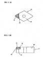
A hard sintered body indexable insert 51 shown in Fig. 5 is obtained
by forming a concave hollow at a corner part of a tool substrate 55, thereafter
fitting a composite hard sintered body that consists of a hard sintered body 52
and a cemented carbide support 53 thereinto, and brazing them. Cutting
edges are formed at the upper and lower surfaces of the hard sintered body
indexable insert 51.
Likewise, in a hard sintered body indexable insert 51 shown in Figure 6,
a composite hard sintered body that consists of a hard sintered body 52 and a
cemented carbide support 53 is brazed to the overall side face of a corner part of
a tool substrate 55. As in the case shown in Figure 5, cutting edges are formed
at the upper and lower surfaces of the hard sintered body indexable insert 51.
The plurality of cutting edges of the upper and lower surfaces of the tip
can be simultaneously ground by disposing the composite hard sintered body as
shown in Figures 5 and 6, through one grinding step. Machining costs for
each cutting edge of the hard sintered body 52 therefore, can be reduced, and
an inexpensive tool can be provided.
However, the drawback of the constructed conventional tool is that it is
difficult to manufacture a less expensive indexable insert, or achieve high tool
performance.
In other words, cracks and breakage will occur in the hard sintered body
52 if the tool of Figure 5 is used under severe conditions. The cracks and
breakage run through the hard sintered body 52 with low strength, and reach
an unused corner opposite the corner that has been used. As a result, a
problem occurs in which the unused corner can no longer be used.
Further, in the tool of Figure 6, the composite hard sintered body
consisting of the hard sintered body 52 and the cemented carbide support 53 is
brazed only in a direction to be sheared with respect to cutting resistance (main
cutting force). Therefore, there is the possibility that the composite hard
sintered body comes off under severe conditions because of insufficient brazing
strength.
Further, other conventional examples of the hard sintered body
indexable insert are shown in Figures 3 and 4. In Fig. 3, the hard sintered
body 52 is sintered with the cemented carbide support 53 and obtained as a
cubic boron nitride composite hard sintered body in a state of being backed with
the cemented carbide support 53. This composite hard sintered body is brazed
to a seating groove 56 of the tool substrate 55 through a brazing alloy composed
chiefly of Ag and Cu. Thereafter, only a ridge of the hard sintered body 52,
which serves as a cutting edge, is ground, or is ground simultaneously with a
ridge of the tool substrate 55, and thus the hard sintered body indexable insert
51 shown in Fig. 3 is obtained.
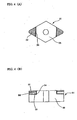
In Figure 4, a plurality of composite hard sintered bodies are brazed to
the upper surface of the tool substrate 55, and are ground. Thereby, a
plurality of cutting edges are simultaneously ground in one step. This makes
it possible to reduce machining costs for each cutting edge of the hard sintered
body, and makes it possible to provide a tool at low manufacturing cost for the
single cutting edge.
In order to manufacture a less expensive hard sintered body indexable
insert such as the tools shown in Figures 3 and 4, there is a need to further
integrate the composite hard sintered body with respect to the single tool
substrate 55. Specifically, there is a need to dispose the composite hard
sintered body not only at the corner part of the upper surface of the hard
sintered body indexable insert 51 but also at the nose part of the lower surface
of the hard sintered body indexable insert 51.
However, a brazing alloy of a soft metal chiefly composed of Ag and Cu
has been conventionally used to bond such a composite hard sintered body.
Brazing is carried out by heating it to a temperature such that the liquid phase
of the brazing alloy appears in the atmosphere while using a high-frequency
heating machine or the like. It was difficult to bond multiple composite hard
sintered bodies in terms of positioning for the following reasons.
For example, a composite hard sintered body is brazed to the corner part
of the upper surface of the hard sintered body indexable insert by use of a
conventional brazing alloy, and thereafter it is turned upside down. While
heating is being carried out by the high-frequency heating machine so as to
braze the composite hard sintered body to the corner part of the upper surface,
a brazing alloy of the lower surface of the composite hard sintered body, which
has been brazed, is also heated and softened. Therefore, in the composite hard
sintered body of the lower surface, which has been brazed, there is a case in
which the position thereof deviates as a result of gravity, or in which the
composite hard sintered body itself falls from the tool substrate. Therefore, it
was substantially impossible to complete the tool.
In contrast, in order to remove a bond interface between the hard
sintered body and the cemented carbide support, the idea of bonding the hard
sintered body onto the tool substrate without the cemented carbide support has
been proposed. This tool structure is disclosed in Japanese Published
Unexamined Patent Application Tokukaihei 11-320218.
It is a hard sintered body indexable insert in which a hard sintered body
of diamond or of cubic boron nitride is brazed directly to a tool substrate in a
vacuum or in an inert gas atmosphere by use of a brazing alloy that constitutes
a bonding layer comprising Ti and/or Zr and Cu.
In a technique disclosed in Japanese Published Unexamined Patent
Application Tokukaihei 11-320218, Cu is included as a component of the
bonding layer. Cu is higher than Ag in elastic modulus, and is preferable also
in a cutting tool used under a heavy load. It additionally discloses a technique
in which the hard sintered body is brazed directly to the tool substrate.
In consideration of the aforementioned conventional techniques, the
present invention provides a hard sintered body indexable insert that contains
cubic boron nitride, that can be inexpensively manufactured without
compromising the performance of a tool, and that is highly completed in a
technical aspect and in a manufacturing aspect, and the present invention
provides a manufacturing method thereof.
Disclosure of Invention
A hard sintered body indexable insert according to an aspect of the
present invention is characterized in that a hard sintered body that contains
cubic boron nitride by 20 vol % or more is brazed to a seating groove formed at a
corner of a tool substrate, and a ridge of the hard sintered body is used as a
cutting edge.
At least a pair of hard sintered bodies or composite hard sintered bodies
are disposed on the upper and lower surfaces in the thickness direction of the
hard sintered body indexable insert. The thickness of a tool substrate part
between a pair of seating grooves is within the range of 30% to 90% with
respect to the thickness of the hard sintered body indexable insert, and the
length of the cutting edge of the hard sintered body or of the composite hard
sintered body is within the range of 0.5 mm to 4.0 mm.
Said bonding layer of the brazing alloy is characterized by containing Ti
and/or Zr by 0.5 to 65 wt % and further containing Cu.
A manufacturing method for manufacturing this hard sintered body
indexable insert is described as follows. A brazing alloy with which a hard
sintered body or a composite hard sintered body that contains cubic boron
nitride by 20 vol % or more is brazed to a seating groove formed at a corner of
the tool substrate is made paste-like by mixing a powdery brazing alloy that
contains Ti and/or Zr by 0.5 to 65 wt % and further contains Cu with an organic
binder.
Thereafter, the hard sintered body or the composite hard sintered body
is bonded to the seating groove of the upper surface of the tool substrate
through the paste-like brazing alloy, a solvent component in the organic binder
is then evaporated, and the hard sintered body or the composite hard sintered
body is temporarily fastened. Thereafter, the hard sintered body or the
composite hard sintered body is bonded to the seating groove of the lower
surface of the tool substrate through the paste-like brazing alloy, the organic
binder is then evaporated, and the hard sintered body or the composite hard
sintered body is temporarily fastened. Thereafter, the hard sintered body
indexable insert in which the hard sintered body or the composite hard sintered
body is temporarily fastened to the upper and lower surfaces is heated, brazed,
and firmly bonded in a vacuum or in an inert gas atmosphere.
Brief Description of Drawings
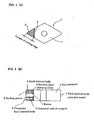
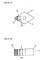
Figure 1 shows a front view and a sectional view of a hard sintered body
indexable insert according to an embodiment of the present invention.
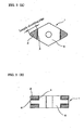
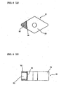
Figure 2 shows a front view and a sectional view of a hard sintered body
indexable insert according to another embodiment of the present invention.
Figure 3 shows a front view and a sectional view of a conventional
sintered body indexable insert.
Figure 4 shows a front view and a sectional view of another
conventional sintered body indexable insert.
Figure 5 shows a front view and a sectional view of still another
conventional sintered body indexable insert.
Figure 6 shows a front view and a sectional view of still another
conventional sintered body indexable insert.
Best Mode for Carrying Out the Invention
The present inventors have earnestly sought a method for
inexpensively manufacturing a hard sintered body indexable insert that
contains cubic boron nitride without compromising the performance of a tool.
As a result, a hard sintered body indexable insert was manufactured in which a
hard sintered body that contains cubic boron nitride by 20 vol % or more is
bonded to a seating groove formed at a corner of a tool substrate, and a ridge of
the hard sintered body is used as a cutting edge. In Figure 1, at least one pair
of composite hard sintered bodies that each consist of a hard sintered body 2
and a cemented carbide support 3 are disposed on the upper and lower surfaces
in a thickness direction of a hard sintered body indexable insert 1. The
thickness of a tool substrate 5 between a pair of seating grooves is within the
range of 30% to 90% with respect to the thickness of the hard sintered body
indexable insert 1, and the length of the cutting edge of the hard sintered body
2 is within the range of 0.5 mm to 4.0 mm. Said bonding layer 4 of the brazing
alloy contains Ti and/or Zr by 0.5 to 65 wt % and further contains Cu.
Herein, the tool substrate 5 with high strength exists between the hard
sintered bodies 2 brazed to seating grooves 6 of the upper and lower surfaces,
respectively, of the hard sintered body indexable insert 1 of the present
invention. Therefore, despite the occurrence of cracks and breakage in the
cutting edge of a hard sintered body 2 under severe cutting conditions, the
cracks and breakage will not run to an unused corner opposite to the corner
that has been used.
Additionally, since there is a vertical brazed plane to main cutting force
among brazing planes, the hard sintered body 2 does not fall off by a shearing
force. The tool substrate 5 may be made of any material so long as it is higher
in strength than the hard sintered body 2. However, cemented carbide that
has a small difference in thermal expansion with the hard sintered body 2 is
preferable in order to prevent cracks and breakage of the hard sintered body 2
caused by heating when brazed.
If the thickness of the tool substrate 5 sandwiched between the pair of
seating grooves 6 reaches less than 30% with respect to the thickness of the
hard sintered body indexable insert 1, there is an increased possibility that the
cutting resistance that occurs while cutting will concentrate on the corner of
the seating groove 6 so as to cause breakage from the corner of the seating
groove 6 while cutting. On the other hand, if it exceeds 90%, the thickness of
the part of the hard sintered body 2 will thin, causing the flank wear of the
cutting edge to easily exceed the layer of the hard sintered body 2. In this case,
the flank wear progresses rapidly, and increases possibility of a reduced tool
life.
Therefore, the thickness of the tool substrate 5 sandwiched between the
pair of seating grooves 6 is desirably within the range of 30% to 90% with
respect to the thickness of the hard sintered body indexable insert 1.
More desirably, it is within the range of 30% to 60%, in consideration of
the composite hard sintered body with which the cemented carbide support 3 is
backed.
The thickness of each hard sintered body 2 is desirably 0.8 mm to 1.6
mm. If the thickness is less than 0.8 mm, a brazing area in the thickness
direction decreases. If the hard sintered body 2 whose thickness exceeds 1.6
mm is brazed to the upper and lower surfaces, the thickness of the tool
substrate 5 thins, and the possibility of breakage to occur from the corner of the
seating groove 6 will increase when cutting under severe conditions.
Thus, in order to secure the thickness of the hard sintered body 2
without thinning the part of the tool substrate 5, the structure of Figure 2 in
which the hard sintered body 2 is bonded directly to the tool substrate 5
through the bonding layer 4 is preferable to the conventional composite hard
sintered body backed with the cemented carbide support 3.
If the cutting-edge length of the hard sintered body exceeds 4.0 mm, the
length from the bottom corner of the seating groove 6 to the cutting edge is
increased, and an arm length of moment become long. Accordingly, large
stress caused by the cutting resistance concentrates on the corner of the seating
groove 6, thus enhancing the possibility that breakage will occur from this
seating groove corner while cutting. If the cutting-edge length is less than 0.5
mm, there will be frequent occurrences of which a cutting-edge length
necessary for cutting cannot be obtained. Therefore, desirably, the cutting-edge
length of the hard sintered body 2 is within the range of 0.5 mm to 4.0
mm.
On the other hand, since the pair of hard sintered bodies 2 are disposed
on the upper and lower surfaces of the hard sintered body indexable insert 1,
the execution of one process for forming the cutting edge at the corner part of
the hard sintered body 2 (i.e., process for grinding two sides between which the
corner part is sandwiched and grinding one part) makes it possible to form the
two upper and lower cutting edges, and makes it possible to greatly reduce
tool-machining costs for one cutting edge of the hard sintered body 2.
Further, for the same reason as above, since the number of pairs of
upper and lower hard sintered bodies 2 is increased by disposing them at the
other corner parts, machining costs for one cutting edge of the hard sintered
body 2 or the cost of the tool substrate 5 falls. This increasingly reduces the
manufacturing costs for one cutting edge of the hard sintered body 2.
Therefore, it is more desirable to dispose of the pair of upper and lower hard
sintered bodies 2 at all corner parts, which can be used for cutting-edges.
On the other hand, the present inventors have found that the hard
sintered body 2 or the composite hard sintered body can be brazed to the upper
and lower surfaces of the tool substrate 5 according to the following method.
In the present invention, a brazing alloy that contains Ti or Zr is used.
This brazing alloy conventionally has been used for Ti bonding or ceramic
bonding, and rarely has been used for tools as in the present invention. Ti or
Zr has a high melting point, and therefore brazing temperature becomes high.
Additionally, Ti or Zr is an easily oxidized metal, and therefore brazing cannot
be carried out in the atmosphere. The brazing must be carried out at least in
an inert gas or in a vacuum. Therefore, since the positioning of a hard
sintered body or a composite hard sintered body cannot be operated directly, it
has been considered that practical application cannot be accomplished from the
viewpoint of cost.
However, as a result of studies, the present inventors have found that, if
a brazing alloy of the present invention is used, brazing can be carried out
merely by inserting the material into an airtight container and by
appropriately controlling the temperature, with high positioning accuracy and
without allowing a lower hard sintered body to fall off. Concerning the
composition of the brazing alloy after being brazed, easily evaporable
components tend to evaporate and decrease because the brazing temperature is
high.
A more explanatory description provides that, a paste-like brazing alloy
is prepared by mixing a powdery brazing alloy that contains 0.5 to 65 wt % Ti
and/or Zr and that further contains Cu with an organic binder. Thereafter, a
hard sintered body 2 or a composite hard sintered body is bonded to a part of a
seating groove 6 formed in the upper surface of a tool substrate 5 through the
paste-like brazing alloy. Herein, any material can be used as the organic
binder provides that it has moderate viscosity, such as that of glue, of gelatin,
or of terpineol, and provided that a solvent component of the binder evaporates
at a relatively low temperature. The "low temperature" mentioned here
means temperature less than a solidus line or less than a liquidus line of the
brazing alloy component, and indicates the temperature according to which
such oxidation as changing the quality of the brazing alloy does not occur.
Thereafter, the indexable insert in which the hard sintered body 2 or the
composite hard sintered body 8 is bonded through the paste-like brazing alloy
is heated or is left in the atmosphere at less than the temperature at which a
liquid phase appears from the brazing alloy and in the temperature range in
which the quality of the brazing alloy does not change and is not oxidized. The
solvent component of the organic binder is evaporated from the paste-like
brazing alloy in this manner. Thus, the hard sintered body 2 or the composite
hard sintered body 8 can be temporarily fastened to the tool substrate 5 by the
function of the binder without changing the quality of the brazing alloy.
According to the same procedure, the hard sintered body 2 or the composite
hard sintered body is temporarily fastened to the seating groove 6 of the lower
surface of the tool substrate 5.
The hard sintered body indexable insert 1, which is obtained in this way
and in which at least the pair of hard sintered bodies 2 or composite hard
sintered bodies are temporarily fastened, is brazed by heating in a vacuum or
in an inert gas atmosphere. At this time, since the brazing alloy of the present
invention contains Ti and/or Zr, both of which are active metals, and it has good
wettability to the hard sintered body as opposed to the conventional brazing
alloy which does not have good wettability. The cemented carbide used as the
tool substrate 5 has good wettability to the conventional brazing alloy, and has
good wettability to the brazing alloy of the present invention.
Therefore, even though the eutectic liquid phase component of the
brazing alloy appears by heating, the hard sintered body 2 or the composite
hard sintered body comes to be easily drawn to the seating groove 6 of the tool
substrate 5 since the surface tension of this liquid phase component is high.
Therefore, after the heating is completed, situations do not occur in which the
position of the hard sintered body 2 or of the composite hard sintered body
deviates, or the hard sintered body 2 or the composite hard sintered body itself
falls from the tool substrate 5 as a result of gravity.
Desirably, the composition of the brazing alloy is within the
aforementioned range not only from the viewpoint of the positioning in the
brazing process but also from the viewpoint of cutting performance, because the
brazing alloy whose composition is within the aforementioned range has
excellent bonding strength with respect to the hard sintered body 2 or the
composite hard sintered body.
In particular, a brazing alloy, a part of which contains 20 wt % to 30
wt % Ti and 20 wt % to 30 wt % Zr and the remainder of Cu and inevitable
impurities, is high in hardness, and is suitable for the brazing of the hard
sintered body. A brazing alloy, a part of which contains 0.5 wt % to 20 wt % Ti
and/or Zr and 10 wt % to 40 wt % Cu and the remainder of Ag and inevitable
impurities, is suitable for the composite hard sintered body. Alternatively, a
brazing alloy, a part of which contains 0.5 wt % to 10 wt % Ti and/or Zr, 5 wt %
to 20 wt % In, and 15 wt % to 35 wt % Cu, and the remainder of Ag and
inevitable impurities, is desirable.
Any of the brazing alloys within these ranges are preferable because of
their remarkable effect of decreasing the melting point by a three-component
eutectic or by a four-component eutectic, and they can undergo brazing
processing at a relatively low temperature of 700 to 900°C so as to reduce heat
damage to the hard sintered body 2.
Further, a coating layer is formed on the surface of the thus produced
hard sintered body indexable insert 1 according to a physical vapor deposition
method or a chemical vapor deposition method. That is, there is formed a
coating layer comprising at least one element selected from the group
consisting of elements belonging to groups IVa, Va, VIa in the periodic table
and elements Al, Si, and B, or at least one compound selected from the group
consisting of nitride, carbide, or oxide of at least one metal selected from this
group, and their solid solutions. In this case, the coating layer is preferable
because the cutting performance of the tool is improved by the coating, and
coating costs for one cutting edge of the hard sintered body can be greatly
reduced without compromising tool performance.
As shown in Figure 1, a recess 7 is provided at the brazing part of the
composite hard sintered body of the tool substrate 5. This is effective in the
fact that the composite hard sintered body and the tool substrate can be brazed
with excellent dimensional accuracy. The same applies to the hard sintered
body shown in Figure 2.
Additionally, in the present invention, it is effective to mark a numeral
on each corner of the edge. The conventional indexable insert using the hard
sintered body merely uses one or two corners. In contrast, the indexable
insert of the present invention is effective because the blade exists on the upper
and lower surfaces, and a judgment regarding whether it has been used or not
can be easily made by the numeral.
(Embodiment 1)
The hard sintered body indexable insert 1 shown in Figure 2 was made.
It was made for a purpose to examine an its effect on cutting performance and
on durability by the thickness of the part of the tool substrate 5 between a pair
of seating grooves 6. The pair of upper and lower seating grooves 6 used to
bond the hard sintered body 2 was provided at each corner of the tool substrate
corner, and the depth of the seating groove 6 was variously changed. These
are shown in Table I .
The entire thickness of the hard sintered body
indexable insert 1 was
4.76 mm in each sample, and the length of the cutting-edge was 2.4 mm in each
sample.
Referring to the manufacturing method, a paste-like brazing alloy was
first prepared by mixing a powdery brazing alloy which contains 25 wt % Ti
and 25 wt % Zr and the remainder of Cu and inevitable impurities with
terpineol.
Thereafter, the hard sintered body 2 that contains cubic boron nitride by
50 vol % was bonded through the paste-like brazing alloy to a part of the
seating groove 6 of the upper surface of the tool substrate 5 in which the depth
of the seating groove 6 has been variously changed. Thereafter, in order to
temporarily fasten the hard sintered body 2 onto the tool substrate 5 by
evaporating a solvent component of a binder, the hard sintered body indexable
insert 1 was dried in an atmospheric atmosphere furnace of 100°C.
After drying was completed, the seating groove was turned upside down
so that the lower surface was directed upward, and the hard sintered body 2
was temporarily fastened to the turned seating groove according to the same
procedures.
Thereafter, this hard sintered body indexable insert 1 was subjected to
brazing in a vacuum atmosphere of 1.333×10⁻²Pa and at a temperature of
850°C. Thereafter, in order to form a cutting edge at a ridge of the hard
sintered body 2, the ridge was ground, thereafter a coating layer of TiAlN
whose thickness is 2.0µm was formed on the surface of the hard sintered body
indexable insert 1 according to the PVD method, and the cutting performance
thereof was evaluated.
Table II shows the results.
As a result, the amount of flank wear exceeded the thickness of the hard
sintered body 2 while cutting using the tool of sample No. 1 in which the hard
sintered body 2 is thin, therefore wear rapidly progressed, cutting resistance
increased, and breakage occurred in the cutting edge in a short time. In the
tool of sample No. 6 in which the thickness of the tool substrate 5 is thin, stress
during the cutting concentrated on the corner of the seating groove, and
breakage occurred from the corner at the beginning of the cutting without
resisting the stress.
In sample No. 7 in which the hard sintered body 2 is brazed to the
overall side face of the tool substrate 5, cracks in the upper surface of the tool
that occurred by the cutting evaluation ran through the hard sintered body 2
brazed to the entire side face, and reached the lower surface of the tool. As a
result, the corner of the lower surface of the tool, which was an unused side,
was no longer available.
In contrast, in the tools of sample Nos. 2 through 5 of the present
invention, neither breakage of the tool substrate during cutting, nor rapid flank
wear, nor immediate breakage of the cutting edge occurred in the cutting test,
and cutting could be carried out during its long life. Additionally, after the
use of the upper cutting edge of the hard sintered body, the performance of the
tool was not impaired, preventing breakage of the cutting edge to run to the
lower surface.
(Embodiment 2)
The hard sintered body indexable insert 1 shown in Table III was made
to examine an influence exerted on cutting performance and on durability by
the length of the cutting edge of the hard sintered body 2. That is, in the hard
sintered body indexable insert 1 shown in Table III, a pair of upper and lower
sintered bodies 2 was bonded at each corner of the tool substrate, and the
cutting-edge length of the hard sintered body 2 was variously changed.
The entire thickness of the hard sintered body
indexable insert 1 was
4.76 mm in each sample, and the thickness of the tool substrate between the
seating grooves was 2.66 mm in each sample.
A paste-like brazing alloy was first prepared by mixing a powdery
brazing alloy which contains 2 wt % Ti and 26 wt % Cu and the remainder of Ag
and inevitable impurities with gelatin.
Thereafter, the hard sintered body 2 that contains cubic boron nitride by
65 vol %, in which the length of the cutting edge has been variously changed,
was bonded through the paste-like brazing alloy to a part of the seating groove
6 of the upper surface of the tool substrate 5. Thereafter, in order to
temporarily fasten the hard sintered body 2 onto the tool substrate 5 by
evaporating a solvent component of a binder, the hard sintered body indexable
insert 1 was dried in an atmospheric atmosphere furnace of 80°C.
After drying was completed, the seating groove was turned upside down
so that the lower surface thereof was directed upward, and the hard sintered
body 2 was temporarily fastened to the turned seating groove according to the
same procedures.
Thereafter, the hard sintered body indexable insert 1 was brazed in an
argon atmosphere and at a temperature of 830°C such that parts to be brazed
do not come in contact with other materials. Thereafter, in order to form a
cutting edge at a ridge of the hard sintered body 2, the ridge was ground, and
the cutting performance thereof was evaluated.
Table IV shows the results.
As a result, in the tool of sample No. 8 in which the cutting edge of the
hard sintered body 2 is short, chipping occurred in the vicinity of the boundary
between the hard sintered body 2 and the tool substrate 5 while cutting
because the cutting edge of the hard sintered body 2 was short. This caused
breakage at the beginning of the cutting, and made it impossible to continue
the cutting operation.
In the tool of sample No. 13 in which the cutting edge is long, the length
of the part of the tool substrate 5 between the upper and lower seating grooves
6 is long, and therefore there is considerable stress at the bottom corner of the
seating groove 6 while cutting. Breakage occurred from this corner at the
beginning of the cutting operation without resisting the stress.
In contrast, in the tools of sample Nos. 9 through 12 of the present
invention, cutting could be carried out during its long life while preventing
breakage to occur at the beginning of the cutting.
(Embodiment 3)
The hard sintered body indexable insert having the structure shown in
Figure 1 that had been obtained from the composite hard sintered body was
made. The entire thickness of the hard sintered body indexable insert was
4.76 mm, and the thickness of the tool substrate between the seating grooves
was 2.66 mm. The composite hard sintered body used in this example
contained cubic boron nitride by 50 vol %, and the thickness of the hard
sintered body and that of the cemented carbide support were each 1 mm.
A paste-like brazing alloy was prepared by mixing a powdery brazing
alloy which contains 2 wt % Ti and 26 wt % Cu and the remainder of Ag and
inevitable impurities with gelatin. Thereafter, the composite hard sintered
body having a cutting-edge length of 3 mm was bonded through the paste-like
brazing alloy to a part of the seating groove of the upper surface of the tool
substrate. Thereafter, in order to temporarily fasten the composite hard
sintered body onto the tool substrate by evaporating a solvent component of a
binder, the hard sintered body indexable insert was dried in an atmospheric
atmosphere of 80°C. After drying was completed, the seating groove was
turned upside down so that the lower surface thereof was directed upward, and
the composite hard sintered body was temporarily fastened to the turned
seating groove according to the same procedures.
Thereafter, the hard sintered body indexable insert was brazed in an
argon atmosphere and at a temperature of 830°C. Thereafter, in order to form
a cutting edge at a ridge of the composite hard sintered body, the ridge was
ground, and the cutting performance thereof was evaluated.
As a result of the cutting test that was made in the same way as in
Embodiment 2, the hard sintered body indexable insert of the present invention
could perform cutting operation during its long life.
Industrial Applicability
A hard sintered body indexable insert has been invented which is
capable of brazing a hard sintered body that contains cubic boron nitride by 20
vol % or more to all corners of a tool substrate and to the upper and lower
surfaces thereof. A manufacturing method for manufacturing the hard sintered
body indexable insert also has been invented.
The present invention is characterized in that a brazing alloy a part of
which contains Ti and/or Zr and the remainder of which consists of Cu and
inevitable impurities is used as a typical brazing alloy, and the hard sintered
body is brazed to the tool substrate by heating it in a vacuum or in an inert gas
atmosphere, as opposed to high-frequency heating at a high temperature. The
present invention is further characterized in that, as optimum conditions, the
thickness of the tool substrate between the upper and lower seating grooves is
set to be 30% to 90% of the entire thickness of the hard sintered body indexable
insert, and the cutting-edge length of the hard sintered body is set to be 0.5 mm
to 4.0 mm.
According to the present invention, machining costs for one cutting edge
of the hard sintered body can be reduced, and the tool substrate can be
effectively used. In other words, a hard sintered body indexable insert can be
provided which is excellent in performance and in durability and which leads to
cost-efficiency.