EP1302147B1 - Docking system for a self-propelled working tool - Google Patents
Docking system for a self-propelled working tool Download PDFInfo
- Publication number
- EP1302147B1 EP1302147B1 EP02077337A EP02077337A EP1302147B1 EP 1302147 B1 EP1302147 B1 EP 1302147B1 EP 02077337 A EP02077337 A EP 02077337A EP 02077337 A EP02077337 A EP 02077337A EP 1302147 B1 EP1302147 B1 EP 1302147B1
- Authority
- EP
- European Patent Office
- Prior art keywords
- docking
- tool
- transmission
- docking station
- station
- Prior art date
- Legal status (The legal status is an assumption and is not a legal conclusion. Google has not performed a legal analysis and makes no representation as to the accuracy of the status listed.)
- Expired - Lifetime
Links
- 238000003032 molecular docking Methods 0.000 title claims abstract description 165
- 230000005540 biological transmission Effects 0.000 claims abstract description 90
- 230000000630 rising effect Effects 0.000 claims abstract description 15
- 238000005498 polishing Methods 0.000 claims abstract description 3
- 238000006748 scratching Methods 0.000 claims abstract description 3
- 238000010407 vacuum cleaning Methods 0.000 claims abstract description 3
- 238000012216 screening Methods 0.000 claims description 9
- 238000007599 discharging Methods 0.000 claims description 2
- 238000013461 design Methods 0.000 description 4
- 208000007101 Muscle Cramp Diseases 0.000 description 3
- 238000000034 method Methods 0.000 description 3
- 244000025254 Cannabis sativa Species 0.000 description 2
- XEEYBQQBJWHFJM-UHFFFAOYSA-N Iron Chemical compound [Fe] XEEYBQQBJWHFJM-UHFFFAOYSA-N 0.000 description 2
- 239000000446 fuel Substances 0.000 description 2
- 230000001681 protective effect Effects 0.000 description 2
- 230000002829 reductive effect Effects 0.000 description 2
- 238000012360 testing method Methods 0.000 description 2
- 239000005028 tinplate Substances 0.000 description 2
- 241000282414 Homo sapiens Species 0.000 description 1
- 241001465754 Metazoa Species 0.000 description 1
- 238000004026 adhesive bonding Methods 0.000 description 1
- 238000004891 communication Methods 0.000 description 1
- 230000000295 complement effect Effects 0.000 description 1
- 230000001419 dependent effect Effects 0.000 description 1
- 229910052742 iron Inorganic materials 0.000 description 1
- 230000005389 magnetism Effects 0.000 description 1
- 239000000463 material Substances 0.000 description 1
- 239000002184 metal Substances 0.000 description 1
- 229910052751 metal Inorganic materials 0.000 description 1
- 239000002991 molded plastic Substances 0.000 description 1
- 230000036961 partial effect Effects 0.000 description 1
- 230000000149 penetrating effect Effects 0.000 description 1
- 230000000284 resting effect Effects 0.000 description 1
- 230000002441 reversible effect Effects 0.000 description 1
- 238000012546 transfer Methods 0.000 description 1
Images


Classifications
-
- G—PHYSICS
- G05—CONTROLLING; REGULATING
- G05D—SYSTEMS FOR CONTROLLING OR REGULATING NON-ELECTRIC VARIABLES
- G05D1/00—Control of position, course, altitude or attitude of land, water, air or space vehicles, e.g. using automatic pilots
- G05D1/02—Control of position or course in two dimensions
- G05D1/021—Control of position or course in two dimensions specially adapted to land vehicles
- G05D1/0212—Control of position or course in two dimensions specially adapted to land vehicles with means for defining a desired trajectory
- G05D1/0225—Control of position or course in two dimensions specially adapted to land vehicles with means for defining a desired trajectory involving docking at a fixed facility, e.g. base station or loading bay
-
- A—HUMAN NECESSITIES
- A47—FURNITURE; DOMESTIC ARTICLES OR APPLIANCES; COFFEE MILLS; SPICE MILLS; SUCTION CLEANERS IN GENERAL
- A47L—DOMESTIC WASHING OR CLEANING; SUCTION CLEANERS IN GENERAL
- A47L9/00—Details or accessories of suction cleaners, e.g. mechanical means for controlling the suction or for effecting pulsating action; Storing devices specially adapted to suction cleaners or parts thereof; Carrying-vehicles specially adapted for suction cleaners
- A47L9/009—Carrying-vehicles; Arrangements of trollies or wheels; Means for avoiding mechanical obstacles
-
- A—HUMAN NECESSITIES
- A47—FURNITURE; DOMESTIC ARTICLES OR APPLIANCES; COFFEE MILLS; SPICE MILLS; SUCTION CLEANERS IN GENERAL
- A47L—DOMESTIC WASHING OR CLEANING; SUCTION CLEANERS IN GENERAL
- A47L9/00—Details or accessories of suction cleaners, e.g. mechanical means for controlling the suction or for effecting pulsating action; Storing devices specially adapted to suction cleaners or parts thereof; Carrying-vehicles specially adapted for suction cleaners
- A47L9/28—Installation of the electric equipment, e.g. adaptation or attachment to the suction cleaner; Controlling suction cleaners by electric means
- A47L9/2805—Parameters or conditions being sensed
-
- A—HUMAN NECESSITIES
- A47—FURNITURE; DOMESTIC ARTICLES OR APPLIANCES; COFFEE MILLS; SPICE MILLS; SUCTION CLEANERS IN GENERAL
- A47L—DOMESTIC WASHING OR CLEANING; SUCTION CLEANERS IN GENERAL
- A47L9/00—Details or accessories of suction cleaners, e.g. mechanical means for controlling the suction or for effecting pulsating action; Storing devices specially adapted to suction cleaners or parts thereof; Carrying-vehicles specially adapted for suction cleaners
- A47L9/28—Installation of the electric equipment, e.g. adaptation or attachment to the suction cleaner; Controlling suction cleaners by electric means
- A47L9/2836—Installation of the electric equipment, e.g. adaptation or attachment to the suction cleaner; Controlling suction cleaners by electric means characterised by the parts which are controlled
- A47L9/2852—Elements for displacement of the vacuum cleaner or the accessories therefor, e.g. wheels, casters or nozzles
-
- A—HUMAN NECESSITIES
- A47—FURNITURE; DOMESTIC ARTICLES OR APPLIANCES; COFFEE MILLS; SPICE MILLS; SUCTION CLEANERS IN GENERAL
- A47L—DOMESTIC WASHING OR CLEANING; SUCTION CLEANERS IN GENERAL
- A47L9/00—Details or accessories of suction cleaners, e.g. mechanical means for controlling the suction or for effecting pulsating action; Storing devices specially adapted to suction cleaners or parts thereof; Carrying-vehicles specially adapted for suction cleaners
- A47L9/28—Installation of the electric equipment, e.g. adaptation or attachment to the suction cleaner; Controlling suction cleaners by electric means
- A47L9/2868—Arrangements for power supply of vacuum cleaners or the accessories thereof
- A47L9/2873—Docking units or charging stations
-
- A—HUMAN NECESSITIES
- A47—FURNITURE; DOMESTIC ARTICLES OR APPLIANCES; COFFEE MILLS; SPICE MILLS; SUCTION CLEANERS IN GENERAL
- A47L—DOMESTIC WASHING OR CLEANING; SUCTION CLEANERS IN GENERAL
- A47L9/00—Details or accessories of suction cleaners, e.g. mechanical means for controlling the suction or for effecting pulsating action; Storing devices specially adapted to suction cleaners or parts thereof; Carrying-vehicles specially adapted for suction cleaners
- A47L9/28—Installation of the electric equipment, e.g. adaptation or attachment to the suction cleaner; Controlling suction cleaners by electric means
- A47L9/2889—Safety or protection devices or systems, e.g. for prevention of motor over-heating or for protection of the user
-
- A—HUMAN NECESSITIES
- A47—FURNITURE; DOMESTIC ARTICLES OR APPLIANCES; COFFEE MILLS; SPICE MILLS; SUCTION CLEANERS IN GENERAL
- A47L—DOMESTIC WASHING OR CLEANING; SUCTION CLEANERS IN GENERAL
- A47L9/00—Details or accessories of suction cleaners, e.g. mechanical means for controlling the suction or for effecting pulsating action; Storing devices specially adapted to suction cleaners or parts thereof; Carrying-vehicles specially adapted for suction cleaners
- A47L9/28—Installation of the electric equipment, e.g. adaptation or attachment to the suction cleaner; Controlling suction cleaners by electric means
- A47L9/2894—Details related to signal transmission in suction cleaners
-
- G—PHYSICS
- G05—CONTROLLING; REGULATING
- G05D—SYSTEMS FOR CONTROLLING OR REGULATING NON-ELECTRIC VARIABLES
- G05D1/00—Control of position, course, altitude or attitude of land, water, air or space vehicles, e.g. using automatic pilots
- G05D1/02—Control of position or course in two dimensions
- G05D1/021—Control of position or course in two dimensions specially adapted to land vehicles
- G05D1/0259—Control of position or course in two dimensions specially adapted to land vehicles using magnetic or electromagnetic means
- G05D1/0265—Control of position or course in two dimensions specially adapted to land vehicles using magnetic or electromagnetic means using buried wires
-
- A—HUMAN NECESSITIES
- A47—FURNITURE; DOMESTIC ARTICLES OR APPLIANCES; COFFEE MILLS; SPICE MILLS; SUCTION CLEANERS IN GENERAL
- A47L—DOMESTIC WASHING OR CLEANING; SUCTION CLEANERS IN GENERAL
- A47L2201/00—Robotic cleaning machines, i.e. with automatic control of the travelling movement or the cleaning operation
- A47L2201/02—Docking stations; Docking operations
Definitions
- the subject invention refers to a docking system.
- the solar cell driven lawn mover called Solar Mower
- the solar cell driven lawn mover cuts the grass within a border cable, which has been placed in order to fence off the cutting area.
- the border cable is buried into the ground.
- a signal generator feeds the border cable with current, whose magnetic field affects a sensing unit on the working tool. Since the working tool is driven by solar cell energy it is reduced to work with very low power, only slightly more than 10 watt. This means that the maximum ground area which the working tool could manage to cut will be limited.
- the solar cell operation as well as the demand for low power consumption lead to a relatively complicated and expensive design.
- US 5 324 948 A discloses a docking system which comprises an autonomous mobile robot for radiological surveys and a docking station at which the robot's battery can be recharged.
- the robot is guided to the docking station by means of an infrared beam emitted by the docking station and detected by the robot.
- the docking station is provided with a charging prong extending horizontally, which cooperates with a socket on the robot facing outwardly in a horizontal direction.
- the direction in which the charging prong is inserted into the socket is, thus, the same as the direction of the robot approaching the docking station.
- the docking station comprises an earth metal base plate intended to be placed on the ground or a floor, and a rising part on which the charging prong is mounted. In the docked position the robot rests on the base plate.
- US 5 440 216 A discloses a docking system comprising a robot floor cleaner and a docking station for recharging the robot's battery.
- the robot is guided to the vicinity of the docking station by ultrasonic waves emitted by the station. Accurate docking is then achieved by magnets and magnetic sensors mounted on both the robot and the docking station.
- a direct-current applying plug on the docking station engages a charging receptacle on the robot in horizontal direction.
- the docking station comprises a base plate and a rising part on which the charging plug is mounted. In the docking manoeuvre the robot rides with its wheels up on the docking station base plate.
- the purpose of the subject invention is to create a docking system, which is protected from dirt.
- the docking system essentially comprises at least one docking station for at least one self-propelled working tool, and includes the working tool itself, preferably intended for attendance of ground or floor, such as grass-cutting, moss-scratching, watering vacuum-cleaning, polishing, transportation etc., wherein the docking station and the tool can by way of emitted signals establish contact with each other, so that the tool can drive up to the docking station, and the docking station is provided with at least one first transmission part for transmission of energy and/or information between the docking station and the tool, which is provided with at least one cooperating second transmission part.
- the transmission part(s) of the working tool(s) is/are arranged on the upper side of the tool's body.
- the transmission part(s) are protected from dirt.
- the docking station is designed as or provided with a base plate, intended to be placed on ground or floor.
- the transmission part(s) of the docking station preferably face(s) downwards and the transmission part(s) of the working tool face(s) upwards.
- the transmission part(s) of the docking station is or are particularly weather-protected.
- the docking station is so adapted that the tool with any part, such as wheel/s or body, can drive up on the docking station. Since the tool can drive up on the docking station with any part it is assured that the tool will end up in a sufficiently exact position in relation to the transmission part/s. In case the docking station shall be placed on a lawn or another rough ground, this matter of fact is extremely important.
- contact between the tool and the docking station is established by way of a first cable, called search cable. Its one connection leads to the station in a docking direction, so that the tool can drive up to the station in the desired docking direction.
- the transmission parts of the docking station as well as the working tool are preferably adapted for transmitting electric energy between the docking station and the tool.
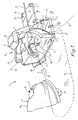
- Figure 1 shows in perspective a working tool, such as a lawn mover placed on a lawn, on its way towards a docking station. Only the front part of the tool is illustrated.
- Figure 2 shows in perspective how the tool has driven up and taken up a docking position at the docking station.
- Figure 3 shows the tool and the docking station seen from the side in the same position as in figure 2. From the figure it becomes evident that the transmission parts of the tool and the station have established contact with each other.
- Figure 4 illustrates in a detailed enlargement the established contact between the transmission parts.
- the transmission part of the station has a somewhat different design in figure 4 than in figure 3.
- numeral reference 1 designates a docking system in accordance with the invention. It comprises a docking station 2 and a working tool 3, and to a certain extent these are adapted to each other.
- the system could also include one docking station and several working tools, or several docking stations and one or several working tools.
- the working tool 3 is self-propelled and has a number of wheels 15, usually four or three wheels, or, two wheels with complementary supporting points.
- the tool has two large rear wheels and two smaller self-adjusting link wheels as front wheels.
- the rear wheel's rotational speed and rotational direction are individually controlled by way of a microprocessor. In this manner the tool can drive forwards or backwards and turn in different desirable directions.
- the tool could also have one front link wheel and possibly steerable front wheels and synchronously driven rear wheels.
- the tool 3 is equipped with a body 16 and another two transmission parts 7, 8 are located on the upper side of the body far forwards and adjacent the middle of the body, seen in a lateral view.
- This location is advantageous considering the fact that the inclination of the ground under the docking station and the tool's wheels, especially its rear wheels, can vary.
- This location of the transmission parts is also suitable considering possible dirtying of the tool.
- the transmission parts 7, 8 are intended to cooperate with the first transmission parts 5, 6, which are located in the docking station.
- the transmission parts of the tool and the station are in the illustrated case adapted for transmitting electric energy between the docking station and the tool in connection with charging, or possibly discharging, of an electric accumulator, located in the tool.
- the accumulator is not shown in any figure.
- For this transmission is preferably used at least two first transmission parts 5, 6 of the docking station, and at least two second transmission parts 7, 8 of the working tool.
- the docking station is thus used for transmitting electric energy for battery-charging, but also other kinds of transmission are possible, e.g. information could be transmitted from the station on to the tool or vice versa by way of further transmission parts, or, by way of the existing ones, so that these can transfer both electric energy and electric information. It could be a matter of transmission of data, but also transmission of simple mechanical information, such as the tool informs that "I am now on the spot", by pushing a button. Furthermore, transmission parts for energy in form of petrol or other power fuels are also conceivable. And of course there can be transmission parts for energy both in form of different fuels and in form of electric power.
- the docking station is mainly composed of a base plate 9, which is provided with at least one rising part.
- the first transmission parts 5, 6; 5', 6' of the docking station are placed in a rising part 11, called transmission head 11, which is placed higher up than the base plate 9 and a possible ramp 10.
- the transmission head 11 rises up over the front part of the tool when the tool is in the docking position.
- the transmission head is mounted either directly to the base plate or onto a possible ramp 10, which also rises up from the base plate.
- a part rising from the base plate is shaped like a ramp 10, which in a direction from the outer surrounding part of the docking station and inwards rises higher and higher up from the base plate in order to cooperate with the tool's body, in that the ramp forces its way underneath the body making it rise when the tool moves forwards.
- the ramp in accordance with the shown embodiment is intended for a docking system with only one docking direction 4. When the tool moves forwards the ramp extends under the mid part of the body, and the lower edge of the body gets into contact with the ramp and slides up along this so that the tool's front wheels lose contact with the ground. This becomes apparent by comparing with the final docking position according to figure 3. It means that the tool's front end is supported against the ramp approximately at the mid part of the tool in its sideways direction.
- the second transmission parts 7, 8 are placed at the upper side of the tool and far forward. It means that the transmission parts are located in a longitudinal direction adjacent the part of the tool's lower edge which cooperates with the ramp. This is advantageous when the ground under the tool and the docking station is rough. A rising or lowering of the tool's rear end in relation to the ideal position as shown in figure 3 would not affect the contact between the transmission parts of the tool and those of the docking station very much. The same applies if the tool's rear end is angled in relation to the shown ideal position in figure 3, i.e. if for example a rear wheel is raised in relation to the other rear wheel. Since the body is supported at its own mid part in its sideways direction, and the transmission parts are located at the mid part of the body, such an angling will have the least possible influence on the contact between the different transmission parts.
- the ramp could be shaped so that it protrudes like a point. Its upper side inclines upwards in the docking direction and causes the tool's body to rise when the tool is moving forwards.
- the ramp can cooperate with the body in many different ways, preferably at the mid part of the body, in its sideways direction, it could e.g. protrude through an aperture in the body.
- the transmission parts of the tool usually electric contacts, can have a safe placement inside the aperture and be directed optionally, and they could also be resilient.
- the transmission parts of the docking station are then placed on one or several sides of the protruding ramp.
- the docking system could also be designed for a number of docking directions. Nearest to think of might be a double docking station with a second docking direction, which is quite the opposite one to the docking direction 4. In this case a second search cable could be connected in the opposite direction and a possible ramp should be arranged in the opposite direction to the shown one. A second transmission head 11 should point towards the opposite direction.
- the docking station could for instance emit signals of a suitable wavelength within a sector from the station.
- the radial range does not have to be especially long and it is an advantage if it is limited considering any disturbances of other equipment.
- contact should be established without any search cable at all and the tool should move towards the docking station. This could then occur in a very large number of conceivable docking directions within a sector.
- the ramp 10 should have an angular extension that corresponds to the utilized sector.
- the transmission parts of the docking station as well as the tool should be adapted for a number of various docking directions, e.g. a resilient centre contact, corresponding to the transmission part 5, could operate with the transmission part 7, while an exterior ring or sectorial resilient contact, corresponding to the transmission part 6, could cooperate with the transmission part 8. Consequently, the docking station will have at least two transmission parts 5, 6 in the form of resilient contacts 5, 6, for transmission of electric energy.
- the resilient contacts are formed as resilient tin-plates 5, 6.
- the resilient tin-plates could be large in width in order to decrease the demand for an elaborate docking operation. For example, they could be 60 mm broad each.
- a big advantage with resilient tin-plates is that they are not exposed to friction between any sliding parts. In this manner they do not run the risk of getting stuck in a suspended position, so that the transmission function is at risk.
- Figure 4 shows a partial enlargement of an alternative tin-plate 5'. It is arranged with a marked bend 28 adjacent to its own mid part. The other tin-plate 6' is hidden in the figure, but has a corresponding marked bend 29 adjacent to its own mid part.
- the force direction between the contacts 5', 7 and 6', 8 respectively will change.
- the contacts can create a certain retaining force on the tool 3. This is of great value for a tool whose driving wheels are not locked during docking, e.g. if the drive engines are very smooth-running even when the current is switched off.
- the resilient contacts 5, 6 are of course preferably located in the docking station since this is stationary and these contact are easier to protect than the contacts 7, 8 in the tool.
- the protective cover the transmission head is provided which could of course be pulled further downwards at the sides in order to protect the contacts 5, 6; 5', 6' against wind and weather as well as unintentional finger contact etc.
- the transmission head 11 could also be provided with a protective cover, which then must be pushed away by the tool 3 when docking.
- the tool follows a search cable's 14 first connection 14', which leads to the station in a docking direction 4.
- the tool follows the search cable 14 in that a sensing unit 27, see figure 3, is placed into the tool and detects the magnetic field from the electric signals, which are emitted to the search cable.
- the magnetic field is also affected by other electric signals emitted by electric equipment as well as earth magnetism and iron objects.
- a second cable 19 is used, called border cable.
- border cable is used to fence off the cutting area as well as that area the tool should stay within.
- the mentioned disturbances implies that it would be suitable to make a certain adjustment of the docking sideways. This could be facilitated by that the first connection 14' is led above a bottom plate 17. This is laterally displaceable in relation to the base plate 9.
- the bottom plate 17 will be placed on the ground in the desirable way, so that the first connection 14' can be led into a cable groove 30 at the bottom plate.
- the first connection 14' is thus resting on the bottom plate from where it leads to a signal generator, which usually is located in the transmission head 11, however, it could also be located somewhere else.
- the bottom plate 17 is preferably fastened by a number of cramps 24, which are inserted through apertures in the bottom plate. Thereafter the base plate 9 with its rising parts is placed on top of the bottom plate 17.
- the both plates are joined together by a number of mounting screws 22, which pass down through slots 21, and are fastened onto the bottom plate 17. These mounting screws could be fastened only slightly in order to make a docking test.
- the base plate 9 will be displaced in the suitable direction and the tests will be repeated until the result is satisfactory. Thereafter the mounting screws are tightened and the base plate 9 is fastened with a number of cramps 24 penetrating through aperture 23 in the base plate 9.
- the cramps 24 are U-shaped in order to provide a particularly satisfactory mounting.
- the whole base plate 9 is thus movable in relation to the search cable's first connection 14' in order to enable the desirable adjustment.
- the transmission head 11 could have a displaceable mounting either onto the ramp 10 or onto the base plate 9 itself. Also, it could be firmly mounted onto the ramp 10, which in turn could be laterally displaceable on the base plate 9. This is provided that any screening parts 12, 13 do not reach all the way up to the ramp 10, but enables the desirable adjustment.
- the search cable's 14 first connection 14' is led through or under the docking station along the docking direction 4 at least a certain distance.
- the length of this distance depends on how far forwards or backwards the sensing unit 27 is located in the tool 3.
- the adjustability sideways, i.e. essentially perpendicularly to the docking direction, should be arranged between the first connection 14' of the search cable and the first transmission part 6; 5', 6'.
- the first connection 14' is led over a protrusion 18, which protrudes inside the ramp 10 and is laterally displaceable.
- the protrusion 18 is mounted to the bottom plate 17, but it could also be arranged to be movable inside the ramp in other ways, e.g. the protrusion 18 could be laterally movable by means of adjusting screws which are put through the sides of the ramp. Owing to the fact that the ramp and the base plate are partly cut up the protrusion 18 becomes more apparent.
- the base plate 9 is preferably designed as a moulded plastic plate, in which possible rising parts, such as the ramp 10 and the screening parts 12, 13, are formed directly into the material. It means that there are large cavities inside the ramp as well as the screening parts.
- the first connection 14' could also be led into a cable groove above the base plate 9 und up the ramp 10. It could also be mounted on the underside of the ramp 10. As for the two last-mentioned embodiments it is preferable assumed that the transmission head 11 is laterally adjustable.
- the basic principle for the rising of the search cable is that the search cable's 14 first connection 14' is led through or under the docking station along the docking direction 4 at least a certain distance, and over some part of this distance the first connection is arranged to be raised above the level of the base plate 9 in order to allow the tool to follow the cable more precisely when docking. As becomes apparent from figures 3, due to this rising of the first connection 14' it will come considerably closer to the sensing unit 27 and hereby a more careful following of the cable can be achieved.
- the docking system according to the invention should be co-operating with an electronic bordering system according to Swedish patent application 9703399-7 (see also WO 99/15941 A1).
- the border cable 19 separates the ground area and is shown here on a substantially reduced scale from considerations of space.
- a signal generator feeds the border cable 19 with current containing at least two components of alternating-current with different frequency, and the components are lying in a known relation of time to each other.
- a control unit in the tool can evaluate the difference in signals from the sensing unit 27, caused by the magnetic field's different directions in the inner area A from the outer area C. It means that the tool can separate the inner area A from the outer area C and keep within the inner area A.
- search area B By way of the search cable 14 a special area, called search area B, is created. This area B is located within the inner area A.
- the signal generator feeds the search cable 14 with the same current containing at least two alternating-current components.
- the search cable 14 with the same current containing at least two alternating-current components.
- the time proportions for phase and anti-phase between the cables are given a value differing from 50/50 % the average of the picked up signals in the sensing unit 27 can be distinguished between area A and area B.
- Particularly suitable proportions between the phase and anti-phase times might be one quarter and three quarters or vice versa. Accordingly, by this system the areas A, B and C can be separated. The system functions so that the control unit separates the different areas and not each cable 14, 19, as such.
- the tool 3 usually a lawn mower, usually operates on the principle of random motion within the area A. When its battery charge begins to run down it reacts in a special way when passing from area A to area B, or vice versa.
- the control unit takes note of the passage from area A to area B and the tool turns left with the intension of following the search cable 14 in a clockwise direction towards the docking station 2. In the opposite case, i.e. passage from area B to area A, the tool instead turns right with the intension of following the search cable in a clockwise direction. After this initial turn the tool will change over to a "follow the cable” mode as follows.
- the search cable could as well be followed in an anti-clockwise direction, provided that the anti-clockwise connection 14" instead is drawn in the desirable docking direction 4.
- the tool it might also be possible for the tool to stand still within the area B during a certain time of the day and night.
- the tool's microprocessor with a built-in clock is then simply being programmed to stop within the area B when the tool arrives there during the relevant time. Consequently, the above described electronic search system does not imply any docking system, even if docking is the most common application.
- the search system could also be combined with other docking systems than the above described.
- the base plate 9 is therefore provided with at least one screening part 12, 13, which protrudes from the base plate and has a height adapted to the tool so that it at least locally is higher than the height of the lower edge of the tool's body, so that the screening part/s together with the rising parts, which also are higher than the lower edge of the body, will prevent the tool from driving up to the first transmission part 5, 6 of the docking station in other docking directions than the intended ones.
- the tool is so designed that when it runs into a firm object it will reverse. This occurs when it runs into the outer surfaces of the screening parts 12, 13 as well as the transmission head 11.
- the tool can drive outside the border cable 19 by approximately three decimetres. Owing to this the docking station 2 can be reached by the tool from the side or obliquely from behind. Since the tool will push into the docking station its anchorage is important. This can also be made by substantial ballasting of the station; or by glueing onto a floor, or fastening with double-adherent tape etc.
- the cables 14 and 19 are drawn under ground except when they lead over the docking station 2.
- the second connection 14" of the search cable, as well as one connection of border cable 19, are drawn along the screening part 12, which protect the cables from damage. The cables are led up to the signal generator which is located in the transmission head 11.
Landscapes
- Engineering & Computer Science (AREA)
- Mechanical Engineering (AREA)
- Physics & Mathematics (AREA)
- Automation & Control Theory (AREA)
- Radar, Positioning & Navigation (AREA)
- Remote Sensing (AREA)
- Aviation & Aerospace Engineering (AREA)
- General Physics & Mathematics (AREA)
- Robotics (AREA)
- Electromagnetism (AREA)
- Manipulator (AREA)
- Control Of Position, Course, Altitude, Or Attitude Of Moving Bodies (AREA)
- Harvester Elements (AREA)
- Automatic Tool Replacement In Machine Tools (AREA)
- Portable Nailing Machines And Staplers (AREA)
- Guiding Agricultural Machines (AREA)
- Multi-Process Working Machines And Systems (AREA)
- Handcart (AREA)
- Road Repair (AREA)
Abstract
Description
- The subject invention refers to a docking system.
- The idea to create a working tool, which manage completely by itself, such as a robot lawn mover or a robot vacuum-cleaner, is old, but has been difficult to realize. The solar cell driven lawn mover, called Solar Mower, is however an example of such kind of product. It cuts the grass within a border cable, which has been placed in order to fence off the cutting area. Preferably the border cable is buried into the ground. A signal generator feeds the border cable with current, whose magnetic field affects a sensing unit on the working tool. Since the working tool is driven by solar cell energy it is reduced to work with very low power, only slightly more than 10 watt. This means that the maximum ground area which the working tool could manage to cut will be limited. Furthermore, the solar cell operation as well as the demand for low power consumption lead to a relatively complicated and expensive design.
- An immediate idea would be to create a battery-powered cutting machine, which should be connected manually for recharging its batteries. This would enable a simpler cutting machine, however, at the same time the big advantage of having a fully automatic grass cutting machine would disappear. Obviously, the same also applies for a battery-powered vacuum-cleaner. Docking stations for recharging of battery-powered, loop-controlled trucks are probably known. The design of such kind of docking system is essentially facilitated by the fact that the docking procedure takes place on even floors.
- US 5 324 948 A discloses a docking system which comprises an autonomous mobile robot for radiological surveys and a docking station at which the robot's battery can be recharged. The robot is guided to the docking station by means of an infrared beam emitted by the docking station and detected by the robot. The docking station is provided with a charging prong extending horizontally, which cooperates with a socket on the robot facing outwardly in a horizontal direction. The direction in which the charging prong is inserted into the socket is, thus, the same as the direction of the robot approaching the docking station. The docking station comprises an earth metal base plate intended to be placed on the ground or a floor, and a rising part on which the charging prong is mounted. In the docked position the robot rests on the base plate.
- US 5 440 216 A discloses a docking system comprising a robot floor cleaner and a docking station for recharging the robot's battery. The robot is guided to the vicinity of the docking station by ultrasonic waves emitted by the station. Accurate docking is then achieved by magnets and magnetic sensors mounted on both the robot and the docking station. A direct-current applying plug on the docking station engages a charging receptacle on the robot in horizontal direction. The docking station comprises a base plate and a rising part on which the charging plug is mounted. In the docking manoeuvre the robot rides with its wheels up on the docking station base plate.
- The purpose of the subject invention is to create a docking system, which is protected from dirt.
- The above purpose is achieved in a docking system in accordance with the invention having the characteristics appearing from the appended claims.
- The docking system essentially comprises at least one docking station for at least one self-propelled working tool, and includes the working tool itself, preferably intended for attendance of ground or floor, such as grass-cutting, moss-scratching, watering vacuum-cleaning, polishing, transportation etc., wherein the docking station and the tool can by way of emitted signals establish contact with each other, so that the tool can drive up to the docking station, and the docking station is provided with at least one first transmission part for transmission of energy and/or information between the docking station and the tool, which is provided with at least one cooperating second transmission part.
- Now, the transmission part(s) of the working tool(s) is/are arranged on the upper side of the tool's body. Thus, the transmission part(s) are protected from dirt.
- It is understood and explicitly declared that any subject-matter contained in the PCT application PCT/SE98/02456 with the designation EP (EP 98 965 939.6), which this application is a divisional application of, and not claimed by the claims of EP 98 965 939.6 in the version of the rule 51 (4) communication or the granted version shall be subject-matter of this divisional application and can therefore also be claimed.
- Preferred embodiments are claimed in the dependent claims referring back to
claim 1. - Usually the docking station is designed as or provided with a base plate, intended to be placed on ground or floor.
- The transmission part(s) of the docking station preferably face(s) downwards and the transmission part(s) of the working tool face(s) upwards. In this embodiment, the transmission part(s) of the docking station is or are particularly weather-protected.
- Preferably the docking station is so adapted that the tool with any part, such as wheel/s or body, can drive up on the docking station. Since the tool can drive up on the docking station with any part it is assured that the tool will end up in a sufficiently exact position in relation to the transmission part/s. In case the docking station shall be placed on a lawn or another rough ground, this matter of fact is extremely important.
- In a preferred embodiment of the invention contact between the tool and the docking station is established by way of a first cable, called search cable. Its one connection leads to the station in a docking direction, so that the tool can drive up to the station in the desired docking direction.
- Furthermore, the transmission parts of the docking station as well as the working tool are preferably adapted for transmitting electric energy between the docking station and the tool.
- These and other characteristics and advantages of the invention will become more apparent from the detailed description of various embodiments with the support of the annexed drawing.
- The invention will be described in closer detail in the following by way of various embodiments thereof with reference to the annexed drawing.
- Figure 1 shows in perspective a working tool, such as a lawn mover placed on a lawn, on its way towards a docking station. Only the front part of the tool is illustrated.
- Figure 2 shows in perspective how the tool has driven up and taken up a docking position at the docking station.
- Figure 3 shows the tool and the docking station seen from the side in the same position as in figure 2. From the figure it becomes evident that the transmission parts of the tool and the station have established contact with each other.
- Figure 4 illustrates in a detailed enlargement the established contact between the transmission parts. The transmission part of the station has a somewhat different design in figure 4 than in figure 3.
- In figure 1
numeral reference 1 designates a docking system in accordance with the invention. It comprises adocking station 2 and aworking tool 3, and to a certain extent these are adapted to each other. However, the system could also include one docking station and several working tools, or several docking stations and one or several working tools. - The
working tool 3 is self-propelled and has a number ofwheels 15, usually four or three wheels, or, two wheels with complementary supporting points. In the shown embodiment as becomes apparent from the figures 1-3, the tool has two large rear wheels and two smaller self-adjusting link wheels as front wheels. The rear wheel's rotational speed and rotational direction are individually controlled by way of a microprocessor. In this manner the tool can drive forwards or backwards and turn in different desirable directions. Obviously the tool could also have one front link wheel and possibly steerable front wheels and synchronously driven rear wheels. - The
tool 3 is equipped with abody 16 and another twotransmission parts 7, 8 are located on the upper side of the body far forwards and adjacent the middle of the body, seen in a lateral view. This location is advantageous considering the fact that the inclination of the ground under the docking station and the tool's wheels, especially its rear wheels, can vary. This location of the transmission parts is also suitable considering possible dirtying of the tool. - The
transmission parts 7, 8 are intended to cooperate with thefirst transmission parts 5, 6, which are located in the docking station. The transmission parts of the tool and the station are in the illustrated case adapted for transmitting electric energy between the docking station and the tool in connection with charging, or possibly discharging, of an electric accumulator, located in the tool. The accumulator is not shown in any figure. For this transmission is preferably used at least twofirst transmission parts 5, 6 of the docking station, and at least twosecond transmission parts 7, 8 of the working tool. - Normally, the docking station is thus used for transmitting electric energy for battery-charging, but also other kinds of transmission are possible, e.g. information could be transmitted from the station on to the tool or vice versa by way of further transmission parts, or, by way of the existing ones, so that these can transfer both electric energy and electric information. It could be a matter of transmission of data, but also transmission of simple mechanical information, such as the tool informs that "I am now on the spot", by pushing a button. Furthermore, transmission parts for energy in form of petrol or other power fuels are also conceivable. And of course there can be transmission parts for energy both in form of different fuels and in form of electric power.
- The docking station is mainly composed of a
base plate 9, which is provided with at least one rising part. - For, it is preferable to place the
first transmissions parts 5, 6 of the docking station higher up than thebase plate 9 itself. - Moreover, preferably they should be turned downwards in order to cooperate with the second transmission parts of the tool, which are turned upwards.
- An example of this is the embodiment shown in the drawing figures. It is particularly preferable considering the risk of dirtying of the tool, and also as weather-protection for the transmissions parts of the docking station. The
first transmission parts 5, 6; 5', 6' of the docking station are placed in a risingpart 11, calledtransmission head 11, which is placed higher up than thebase plate 9 and apossible ramp 10. Thetransmission head 11 rises up over the front part of the tool when the tool is in the docking position. The transmission head is mounted either directly to the base plate or onto apossible ramp 10, which also rises up from the base plate. - As appears from the figure there is a
bottom plate 17. Afirst connection 14' ofsearch cable 14 is led over the top of this bottom plate. Thebase plate 9 and thebottom plate 17 are laterally displaceable in relation to each other. This enables a desirable adjustment of the docking procedure. This adjustment is advantageous but not completely necessary. It means thatplate 17 could be excluded. In that case thesearch cable 14 is instead drawn on the ground under the base plate. - A part rising from the base plate is shaped like a
ramp 10, which in a direction from the outer surrounding part of the docking station and inwards rises higher and higher up from the base plate in order to cooperate with the tool's body, in that the ramp forces its way underneath the body making it rise when the tool moves forwards. The ramp in accordance with the shown embodiment is intended for a docking system with only onedocking direction 4. When the tool moves forwards the ramp extends under the mid part of the body, and the lower edge of the body gets into contact with the ramp and slides up along this so that the tool's front wheels lose contact with the ground. This becomes apparent by comparing with the final docking position according to figure 3. It means that the tool's front end is supported against the ramp approximately at the mid part of the tool in its sideways direction. - At the same time, the
second transmission parts 7, 8 are placed at the upper side of the tool and far forward. It means that the transmission parts are located in a longitudinal direction adjacent the part of the tool's lower edge which cooperates with the ramp. This is advantageous when the ground under the tool and the docking station is rough. A rising or lowering of the tool's rear end in relation to the ideal position as shown in figure 3 would not affect the contact between the transmission parts of the tool and those of the docking station very much. The same applies if the tool's rear end is angled in relation to the shown ideal position in figure 3, i.e. if for example a rear wheel is raised in relation to the other rear wheel. Since the body is supported at its own mid part in its sideways direction, and the transmission parts are located at the mid part of the body, such an angling will have the least possible influence on the contact between the different transmission parts. - The ramp could be shaped so that it protrudes like a point. Its upper side inclines upwards in the docking direction and causes the tool's body to rise when the tool is moving forwards. The ramp can cooperate with the body in many different ways, preferably at the mid part of the body, in its sideways direction, it could e.g. protrude through an aperture in the body. In this manner the transmission parts of the tool, usually electric contacts, can have a safe placement inside the aperture and be directed optionally, and they could also be resilient. Preferably the transmission parts of the docking station are then placed on one or several sides of the protruding ramp.
- However, the docking system could also be designed for a number of docking directions. Nearest to think of might be a double docking station with a second docking direction, which is quite the opposite one to the
docking direction 4. In this case a second search cable could be connected in the opposite direction and a possible ramp should be arranged in the opposite direction to the shown one. Asecond transmission head 11 should point towards the opposite direction. - However, it might also be possible to design the docking station for still more docking directions and the docking procedure does not have to follow the search cable's one connection into the docking station. The docking station could for instance emit signals of a suitable wavelength within a sector from the station. The radial range does not have to be especially long and it is an advantage if it is limited considering any disturbances of other equipment. In such a case contact should be established without any search cable at all and the tool should move towards the docking station. This could then occur in a very large number of conceivable docking directions within a sector. Obviously in such a case the
ramp 10 should have an angular extension that corresponds to the utilized sector. Furthermore the transmission parts of the docking station as well as the tool should be adapted for a number of various docking directions, e.g. a resilient centre contact, corresponding to the transmission part 5, could operate with the transmission part 7, while an exterior ring or sectorial resilient contact, corresponding to thetransmission part 6, could cooperate with thetransmission part 8. Consequently, the docking station will have at least twotransmission parts 5, 6 in the form ofresilient contacts 5, 6, for transmission of electric energy. - Preferably the resilient contacts are formed as resilient tin-
plates 5, 6. This becomes apparent from figure 3. The resilient tin-plates could be large in width in order to decrease the demand for an elaborate docking operation. For example, they could be 60 mm broad each. A big advantage with resilient tin-plates is that they are not exposed to friction between any sliding parts. In this manner they do not run the risk of getting stuck in a suspended position, so that the transmission function is at risk. - Figure 4 shows a partial enlargement of an alternative tin-plate 5'. It is arranged with a
marked bend 28 adjacent to its own mid part. The other tin-plate 6' is hidden in the figure, but has a corresponding marked bend 29 adjacent to its own mid part. By way of this bend the force direction between thecontacts 5', 7 and 6', 8 respectively will change. In means that the contacts can create a certain retaining force on thetool 3. This is of great value for a tool whose driving wheels are not locked during docking, e.g. if the drive engines are very smooth-running even when the current is switched off. Theresilient contacts 5, 6 are of course preferably located in the docking station since this is stationary and these contact are easier to protect than thecontacts 7, 8 in the tool. The protective cover the transmission head is provided which could of course be pulled further downwards at the sides in order to protect thecontacts 5, 6; 5', 6' against wind and weather as well as unintentional finger contact etc. - However, at the same time the voltage of the contacts is very low, only about 20 V, so a contact with the live parts shouldn't mean any danger either for human beings or animals. Obviously, the
transmission head 11 could also be provided with a protective cover, which then must be pushed away by thetool 3 when docking. - In the preferred embodiment the tool follows a search cable's 14
first connection 14', which leads to the station in adocking direction 4. The tool follows thesearch cable 14 in that asensing unit 27, see figure 3, is placed into the tool and detects the magnetic field from the electric signals, which are emitted to the search cable. However, the magnetic field is also affected by other electric signals emitted by electric equipment as well as earth magnetism and iron objects. As a rule also asecond cable 19 is used, called border cable. Into this cable electric signals are sent from the docking station. The border cable is used to fence off the cutting area as well as that area the tool should stay within. The mentioned disturbances implies that it would be suitable to make a certain adjustment of the docking sideways. This could be facilitated by that thefirst connection 14' is led above abottom plate 17. This is laterally displaceable in relation to thebase plate 9. - In practical use the
bottom plate 17 will be placed on the ground in the desirable way, so that thefirst connection 14' can be led into acable groove 30 at the bottom plate. Thefirst connection 14' is thus resting on the bottom plate from where it leads to a signal generator, which usually is located in thetransmission head 11, however, it could also be located somewhere else. Thebottom plate 17 is preferably fastened by a number ofcramps 24, which are inserted through apertures in the bottom plate. Thereafter thebase plate 9 with its rising parts is placed on top of thebottom plate 17. The both plates are joined together by a number of mountingscrews 22, which pass down throughslots 21, and are fastened onto thebottom plate 17. These mounting screws could be fastened only slightly in order to make a docking test. In case the tool is not docking in a proper way, i.e. so that thetransmission parts base plate 9 will be displaced in the suitable direction and the tests will be repeated until the result is satisfactory. Thereafter the mounting screws are tightened and thebase plate 9 is fastened with a number ofcramps 24 penetrating throughaperture 23 in thebase plate 9. Thecramps 24 are U-shaped in order to provide a particularly satisfactory mounting. In the shown embodiment thewhole base plate 9 is thus movable in relation to the search cable'sfirst connection 14' in order to enable the desirable adjustment. - However, this adjustment could be made in many different ways and nor is the
bottom plate 17 required, e.g. thefirst connection 14' could be led above thebase plate 9 under apossible ramp 10. In that case thetransmission head 11 could have a displaceable mounting either onto theramp 10 or onto thebase plate 9 itself. Also, it could be firmly mounted onto theramp 10, which in turn could be laterally displaceable on thebase plate 9. This is provided that anyscreening parts ramp 10, but enables the desirable adjustment. - The search cable's 14
first connection 14' is led through or under the docking station along thedocking direction 4 at least a certain distance. The length of this distance depends on how far forwards or backwards thesensing unit 27 is located in thetool 3. The adjustability sideways, i.e. essentially perpendicularly to the docking direction, should be arranged between thefirst connection 14' of the search cable and thefirst transmission part 6; 5', 6'. - In figure 1 it is shown how the
first connection 14' is led over aprotrusion 18, which protrudes inside theramp 10 and is laterally displaceable. Preferably theprotrusion 18 is mounted to thebottom plate 17, but it could also be arranged to be movable inside the ramp in other ways, e.g. theprotrusion 18 could be laterally movable by means of adjusting screws which are put through the sides of the ramp. Owing to the fact that the ramp and the base plate are partly cut up theprotrusion 18 becomes more apparent. Thebase plate 9 is preferably designed as a moulded plastic plate, in which possible rising parts, such as theramp 10 and thescreening parts - The
first connection 14' could also be led into a cable groove above thebase plate 9 und up theramp 10. It could also be mounted on the underside of theramp 10. As for the two last-mentioned embodiments it is preferable assumed that thetransmission head 11 is laterally adjustable. The basic principle for the rising of the search cable is that the search cable's 14first connection 14' is led through or under the docking station along thedocking direction 4 at least a certain distance, and over some part of this distance the first connection is arranged to be raised above the level of thebase plate 9 in order to allow the tool to follow the cable more precisely when docking. As becomes apparent from figures 3, due to this rising of thefirst connection 14' it will come considerably closer to thesensing unit 27 and hereby a more careful following of the cable can be achieved. - Preferably the docking system according to the invention should be co-operating with an electronic bordering system according to Swedish patent application 9703399-7 (see also WO 99/15941 A1). The
border cable 19 separates the ground area and is shown here on a substantially reduced scale from considerations of space. A signal generator feeds theborder cable 19 with current containing at least two components of alternating-current with different frequency, and the components are lying in a known relation of time to each other. Hereby a control unit in the tool can evaluate the difference in signals from thesensing unit 27, caused by the magnetic field's different directions in the inner area A from the outer area C. It means that the tool can separate the inner area A from the outer area C and keep within the inner area A. By way of the search cable 14 a special area, called search area B, is created. This area B is located within the inner area A. Preferably the signal generator feeds thesearch cable 14 with the same current containing at least two alternating-current components. During some part of the time the current in the bothcables sensing unit 27 can be distinguished between area A and area B. Particularly suitable proportions between the phase and anti-phase times might be one quarter and three quarters or vice versa. Accordingly, by this system the areas A, B and C can be separated. The system functions so that the control unit separates the different areas and not eachcable - The
tool 3, usually a lawn mower, usually operates on the principle of random motion within the area A. When its battery charge begins to run down it reacts in a special way when passing from area A to area B, or vice versa. The control unit takes note of the passage from area A to area B and the tool turns left with the intension of following thesearch cable 14 in a clockwise direction towards thedocking station 2. In the opposite case, i.e. passage from area B to area A, the tool instead turns right with the intension of following the search cable in a clockwise direction. After this initial turn the tool will change over to a "follow the cable" mode as follows. After the tool has passed from area B over to area A it turns immediately towards the opposite direction and moves back to area B and after moving from area A to area B it turns again and moves towards area A. This pattern will be repeated very frequently. The zigzag motion over thesearch cable 14 is hardly visible on a lawn, but the result will be that the cutting tool will follow thesearch cable 14 in the desirable direction clockwise, so that it arrives at the docking station in thedocking direction 4. Obviously thesearch cable 14 shall lie in thedocking direction 4, at least the adjacent part outside thedocking station 2. Hereby is assured that the tool moves straight towards the station. Furthermore, the search cable is drawn over the station a suitable length, i.e. thefirst connection 14', so that the tool follows thefirst connection 14' up to the docking position. Since the tool is able to separate area A from area B it can also follow thesearch cable 14 in the desirable direction up to the station. - Obviously the search cable could as well be followed in an anti-clockwise direction, provided that the
anti-clockwise connection 14" instead is drawn in thedesirable docking direction 4. Furthermore, it might also be possible for the tool to stand still within the area B during a certain time of the day and night. The tool's microprocessor with a built-in clock is then simply being programmed to stop within the area B when the tool arrives there during the relevant time. Consequently, the above described electronic search system does not imply any docking system, even if docking is the most common application. Obviously the search system could also be combined with other docking systems than the above described. - Because the tool operates at random it will thus push into the
docking station 2 from different directions. For, it is only when the accumulator have to be recharged that the tool will follow thedocking direction 4 up to the docking station. Preferably thebase plate 9 is therefore provided with at least onescreening part first transmission part 5, 6 of the docking station in other docking directions than the intended ones. - The tool is so designed that when it runs into a firm object it will reverse. This occurs when it runs into the outer surfaces of the
screening parts transmission head 11. For, by way of the electronic bordering system the tool can drive outside theborder cable 19 by approximately three decimetres. Owing to this thedocking station 2 can be reached by the tool from the side or obliquely from behind. Since the tool will push into the docking station its anchorage is important. This can also be made by substantial ballasting of the station; or by glueing onto a floor, or fastening with double-adherent tape etc. As becomes evident from the figure thecables docking station 2. Thesecond connection 14" of the search cable, as well as one connection ofborder cable 19, are drawn along thescreening part 12, which protect the cables from damage. The cables are led up to the signal generator which is located in thetransmission head 11.
Claims (17)
- A docking system (1) which essentially comprisesa) at least one self-propelled working-tool (3), preferably intended for attendance of ground or floor, such as grass-cutting, moss-scratching, watering, vacuum-cleaning, polishing, transportation etc., having a body (16) andb) at least one docking station (2) for the at least one working tool (3),c) wherein the docking station and the tool can by way of emitted signals establish contact with each other, so that the tool can drive up to the docking station, characterized by thatd) the docking station is provided with at least one first transmission part (5, 6; 5', 6') and the working tool is provided with at least one cooperating second transmission part (7, 8) for transmission of energy between the docking station and the working tool,e) wherein the docking station is provided with at least one rising part (10, 11, 12, 13), of which at least one part is used for mounting of the first transmission part(s).f) wherein the tool's second transmission part(s) (7, 8) is/are located on the upper side of the body.
- A docking system (1) according to claim 1, wherein electric signals are sent out from the docking station into at least one first cable (14), called search cable (14), and each cable's first connection (14') respectively leads to the station in a docking direction (4).
- A docking system (1) according to claim 1 or 2, wherein at least two first transmission parts (5, 6) of the docking station, and at least two second transmission parts (7, 8) of the working tool are adapted for transmission of electric energy between the docking station and the tool in connection with recharging, or possibly discharging, of an electric accumulator located in the tool.
- A docking system (1) in accordance with any one of the preceding claims, wherein the docking station is so adapted that the tool with any part, such as wheel/s (15) or body (16) can drive up on the docking station.
- A docking system (1) according to any one of the preceding claims, wherein the docking station is designed as or provided with a base plate (9), intended to be placed on ground or floor.
- A docking system (1) according to claim 5, wherein the docking station's first transmissions part(s) is/are located in a rising part (11), called transmission head (11), which is located higher up than the base plate (9).
- A docking system according to any of the proceeding claims, wherein the docking station's first transmission part/s (5, 6; 5', 6') is/are turned downwards, and the tool's second transmission part/s (7, 8) is/are turned upwards.
- A docking system (1) according to any of the preceding claims, wherein the docking station's and the tool's first and second transmission parts (5-8) are turned sideways, in particular parallel with the base plate (9).
- A docking system (1) according to claim 3 or any claim referring back to claim 3, wherein the docking station has at least two transmission parts (5, 6) for transmission of electric energy arranged in form of resilient contacts (5, 6), in particular in form of resilient tin-plates (5, 6), preferably arranged with a marked bend (28, 29) adjacent to their own mid part.
- A docking system according to any of the preceding claims, wherein at least two first transmission parts and at least two second transmission parts are provided, the two first or second transmission part being arranged laterally beside each other.
- A docking system (1) according to claim 2 or any claim referring back to claim 2, wherein the search cable's (14) first connection (14') is led through or under the station along the docking direction (4) at least a certain distance, and in that an adjustability sideways, i.e. perpendicularly towards the docking direction, is arranged between the first connection (14') of the search cable (14) and the first transmission part (5, 6; 5', 6').
- A docking system (1) according to claim 11, wherein the search cable's (14) first connection (14') is led above a bottom plate (17), which to the most part is arranged under the base plate (9), which in turn is laterally displaceable in relation to the bottom plate.
- A docking system (1) according to any one of the preceding claims, wherein the at least one first transmission part (5, 6; 5', 6') and the at least one cooperating second transmission part (7, 8) for transmission of energy are also used for transmission of information.
- A docking system (1) according to anyone of the preceding claims, wherein the search cable's (14) first connection (14') is led through or under the station along the docking direction (4) at least a certain distance, and over some part of this distance the first connection is arranged to be raised above the level of the base plate (9), in order to allow the tool to follow the cable more precisely when docking.
- A docking system (1) according to any one of the preceding claims, wherein electric signals are sent out from the docking station into a second cable (1), called border cable (19).
- A docking system (1) according to any one of the preceding claims, referring back to claim 5, wherein the base plate (9) is provided with at least one screening part (12, 13), which protrudes from the base plate and has a height adapted to the tool so that it is at least locally higher than the height of the lower edge of the tool's body, so that the screening part/s together with the rising parts, which also are higher than the lower edge of the body, will prevent the tool from driving up to the first transmission part (5, 6) of the docking station in other directions than the intended docking directions.
- A docking system according to any of the preceding claims, wherein the second transmission part(s) of the tool are located far forward on the upper side of body and/or adjacent to the middle of the body.
Applications Claiming Priority (3)
| Application Number | Priority Date | Filing Date | Title |
|---|---|---|---|
| SE9800017 | 1998-01-08 | ||
| SE9800017A SE523080C2 (en) | 1998-01-08 | 1998-01-08 | Docking system for self-propelled work tools |
| EP98965939A EP1058958B1 (en) | 1998-01-08 | 1998-12-30 | Docking system for a self-propelled working tool |
Related Parent Applications (1)
| Application Number | Title | Priority Date | Filing Date |
|---|---|---|---|
| EP98965939A Division EP1058958B1 (en) | 1998-01-08 | 1998-12-30 | Docking system for a self-propelled working tool |
Publications (2)
| Publication Number | Publication Date |
|---|---|
| EP1302147A1 EP1302147A1 (en) | 2003-04-16 |
| EP1302147B1 true EP1302147B1 (en) | 2004-08-11 |
Family
ID=20409805
Family Applications (2)
| Application Number | Title | Priority Date | Filing Date |
|---|---|---|---|
| EP02077337A Expired - Lifetime EP1302147B1 (en) | 1998-01-08 | 1998-12-30 | Docking system for a self-propelled working tool |
| EP98965939A Expired - Lifetime EP1058958B1 (en) | 1998-01-08 | 1998-12-30 | Docking system for a self-propelled working tool |
Family Applications After (1)
| Application Number | Title | Priority Date | Filing Date |
|---|---|---|---|
| EP98965939A Expired - Lifetime EP1058958B1 (en) | 1998-01-08 | 1998-12-30 | Docking system for a self-propelled working tool |
Country Status (8)
| Country | Link |
|---|---|
| US (2) | US6525509B1 (en) |
| EP (2) | EP1302147B1 (en) |
| AT (2) | ATE224603T1 (en) |
| AU (1) | AU753495B2 (en) |
| CA (1) | CA2317598A1 (en) |
| DE (2) | DE69808144T2 (en) |
| SE (1) | SE523080C2 (en) |
| WO (1) | WO1999038237A1 (en) |
Cited By (12)
| Publication number | Priority date | Publication date | Assignee | Title |
|---|---|---|---|---|
| DE102007036152A1 (en) | 2007-08-02 | 2009-02-05 | BSH Bosch und Siemens Hausgeräte GmbH | Housing for fixed station of robot system, especially dust collection robot system, has channel formed when two holding body parts are joined that holds sensor for communications and/or location system |
| DE102007036172A1 (en) | 2007-08-02 | 2009-02-05 | BSH Bosch und Siemens Hausgeräte GmbH | Housing for e.g. base station of dust collecting robot system, has actuator provided in upper housing part plane for actuating switch, where voltage supply to communication part and connection assembly is switched on and off by switch |
| DE102007036173A1 (en) | 2007-08-02 | 2009-02-05 | BSH Bosch und Siemens Hausgeräte GmbH | Housing for a base receiver station of a dust collecting robot comprises a lower part containing an electrical switch, an intermediate part and an upper part connected to the intermediate parts and acting as actuating part for the switch |
| US8306659B2 (en) | 2006-12-06 | 2012-11-06 | F Robotics Acquisitions Ltd. | Autonomous robot |
| DE102007036228B4 (en) * | 2007-08-02 | 2013-10-10 | BSH Bosch und Siemens Hausgeräte GmbH | Method and system for ensuring a connection between a mobile device and a stationary device, in particular between an accumulator-powered dust collection robot and a battery charging station |
| US8618766B2 (en) | 2010-09-27 | 2013-12-31 | Deere & Company | Robot power source charging station |
| WO2014019224A1 (en) | 2012-08-02 | 2014-02-06 | 江苏苏美达五金工具有限公司 | Charging station system of automatic working device |
| US8676378B2 (en) | 2010-11-30 | 2014-03-18 | Positec Power Tools (Suzhou) Co., Ltd. | Robot with docking station, system and method |
| USD760649S1 (en) | 2015-06-22 | 2016-07-05 | Mtd Products Inc | Docking station |
| US9606541B2 (en) | 2004-02-03 | 2017-03-28 | F Robotics Acquisitions Ltd. | Robot docking station and robot for use therewith |
| WO2023182908A1 (en) | 2022-03-21 | 2023-09-28 | Husqvarna Ab | Method and system for operating a solar robot with a wake-up charging position |
| WO2023182912A1 (en) | 2022-03-21 | 2023-09-28 | Husqvarna Ab | Method and system for operating a solar robot with a charging position marker |
Families Citing this family (234)
| Publication number | Priority date | Publication date | Assignee | Title |
|---|---|---|---|---|
| US8412377B2 (en) * | 2000-01-24 | 2013-04-02 | Irobot Corporation | Obstacle following sensor scheme for a mobile robot |
| US7155308B2 (en) | 2000-01-24 | 2006-12-26 | Irobot Corporation | Robot obstacle detection system |
| US8788092B2 (en) * | 2000-01-24 | 2014-07-22 | Irobot Corporation | Obstacle following sensor scheme for a mobile robot |
| US6956348B2 (en) | 2004-01-28 | 2005-10-18 | Irobot Corporation | Debris sensor for cleaning apparatus |
| US7571511B2 (en) | 2002-01-03 | 2009-08-11 | Irobot Corporation | Autonomous floor-cleaning robot |
| US6690134B1 (en) | 2001-01-24 | 2004-02-10 | Irobot Corporation | Method and system for robot localization and confinement |
| US6883201B2 (en) * | 2002-01-03 | 2005-04-26 | Irobot Corporation | Autonomous floor-cleaning robot |
| AU767561B2 (en) * | 2001-04-18 | 2003-11-13 | Samsung Kwangju Electronics Co., Ltd. | Robot cleaner, system employing the same and method for reconnecting to external recharging device |
| AU2003227231B2 (en) * | 2001-04-18 | 2006-03-09 | Samsung Kwangju Electronics Co. Ltd | Robot Cleaner, System Employing the same and Method for Re-Connecting to External Recharging Device |
| US8396592B2 (en) | 2001-06-12 | 2013-03-12 | Irobot Corporation | Method and system for multi-mode coverage for an autonomous robot |
| US7429843B2 (en) | 2001-06-12 | 2008-09-30 | Irobot Corporation | Method and system for multi-mode coverage for an autonomous robot |
| FR2828589B1 (en) * | 2001-08-07 | 2003-12-05 | France Telecom | ELECTRIC CONNECTION SYSTEM BETWEEN A VEHICLE AND A CHARGING STATION OR THE LIKE |
| US9128486B2 (en) | 2002-01-24 | 2015-09-08 | Irobot Corporation | Navigational control system for a robotic device |
| DE10231391A1 (en) * | 2002-07-08 | 2004-02-12 | Alfred Kärcher Gmbh & Co. Kg | Tillage system |
| US8386081B2 (en) | 2002-09-13 | 2013-02-26 | Irobot Corporation | Navigational control system for a robotic device |
| US8428778B2 (en) | 2002-09-13 | 2013-04-23 | Irobot Corporation | Navigational control system for a robotic device |
| KR100561855B1 (en) | 2002-12-30 | 2006-03-16 | 삼성전자주식회사 | Robot localization system |
| GB2407652B (en) * | 2003-02-06 | 2005-07-06 | Samsung Kwangju Electronics Co | Robot system having external recharging apparatus and method for docking robot with external recharging apparatus |
| JP2004237075A (en) * | 2003-02-06 | 2004-08-26 | Samsung Kwangju Electronics Co Ltd | A robot cleaner system having an external charging device and a method of connecting an external charging device of the robot cleaner. |
| US7801645B2 (en) * | 2003-03-14 | 2010-09-21 | Sharper Image Acquisition Llc | Robotic vacuum cleaner with edge and object detection system |
| US7805220B2 (en) * | 2003-03-14 | 2010-09-28 | Sharper Image Acquisition Llc | Robot vacuum with internal mapping system |
| US20040211444A1 (en) * | 2003-03-14 | 2004-10-28 | Taylor Charles E. | Robot vacuum with particulate detector |
| KR100492590B1 (en) * | 2003-03-14 | 2005-06-03 | 엘지전자 주식회사 | Auto charge system and return method for robot |
| US20050010331A1 (en) * | 2003-03-14 | 2005-01-13 | Taylor Charles E. | Robot vacuum with floor type modes |
| US20040200505A1 (en) * | 2003-03-14 | 2004-10-14 | Taylor Charles E. | Robot vac with retractable power cord |
| KR100486737B1 (en) * | 2003-04-08 | 2005-05-03 | 삼성전자주식회사 | Method and apparatus for generating and tracing cleaning trajectory for home cleaning robot |
| KR100928964B1 (en) * | 2003-04-15 | 2009-11-26 | 삼성전자주식회사 | Mobile robot docking station return method and device |
| US7133746B2 (en) * | 2003-07-11 | 2006-11-07 | F Robotics Acquistions, Ltd. | Autonomous machine for docking with a docking station and method for docking |
| KR100820743B1 (en) * | 2003-10-21 | 2008-04-10 | 삼성전자주식회사 | Charging device of mobile robot |
| US7332890B2 (en) * | 2004-01-21 | 2008-02-19 | Irobot Corporation | Autonomous robot auto-docking and energy management systems and methods |
| US20060020369A1 (en) * | 2004-03-11 | 2006-01-26 | Taylor Charles E | Robot vacuum cleaner |
| DE112005000738T5 (en) | 2004-03-29 | 2007-04-26 | Evolution Robotics, Inc., Pasadena | Method and device for determining position using reflected light sources |
| USD510066S1 (en) | 2004-05-05 | 2005-09-27 | Irobot Corporation | Base station for robot |
| KR100548895B1 (en) * | 2004-05-17 | 2006-02-02 | 삼성광주전자 주식회사 | Filling device for robot vacuum cleaner |
| JP4371899B2 (en) * | 2004-05-21 | 2009-11-25 | 株式会社東芝 | Autonomous vehicle system |
| WO2006002385A1 (en) | 2004-06-24 | 2006-01-05 | Irobot Corporation | Programming and diagnostic tool for a mobile robot |
| US8972052B2 (en) | 2004-07-07 | 2015-03-03 | Irobot Corporation | Celestial navigation system for an autonomous vehicle |
| US7706917B1 (en) | 2004-07-07 | 2010-04-27 | Irobot Corporation | Celestial navigation system for an autonomous robot |
| KR100641113B1 (en) * | 2004-07-30 | 2006-11-02 | 엘지전자 주식회사 | Mobile robot and its movement control method |
| WO2006046036A2 (en) * | 2004-10-25 | 2006-05-04 | Jacm Limited | Battery powered floor-care vacuum cleaner |
| US7389156B2 (en) | 2005-02-18 | 2008-06-17 | Irobot Corporation | Autonomous surface cleaning robot for wet and dry cleaning |
| US7620476B2 (en) | 2005-02-18 | 2009-11-17 | Irobot Corporation | Autonomous surface cleaning robot for dry cleaning |
| US8392021B2 (en) | 2005-02-18 | 2013-03-05 | Irobot Corporation | Autonomous surface cleaning robot for wet cleaning |
| KR101247933B1 (en) | 2005-02-18 | 2013-03-26 | 아이로보트 코퍼레이션 | Autonomous surface cleaning robot for wet and dry cleaning |
| US8930023B2 (en) | 2009-11-06 | 2015-01-06 | Irobot Corporation | Localization by learning of wave-signal distributions |
| US20070131505A1 (en) * | 2005-07-16 | 2007-06-14 | Kim Bryan H J | Magnetic Induction Charging System for Vehicles |
| USD541738S1 (en) * | 2005-08-10 | 2007-05-01 | Kyosho Corporation | Battery charger resembling a toy vehicle trailer |
| EP2816434A3 (en) | 2005-12-02 | 2015-01-28 | iRobot Corporation | Autonomous coverage robot |
| ES2706729T3 (en) | 2005-12-02 | 2019-04-01 | Irobot Corp | Robot system |
| EP2251757B1 (en) | 2005-12-02 | 2011-11-23 | iRobot Corporation | Coverage robot mobility |
| WO2007065034A1 (en) | 2005-12-02 | 2007-06-07 | Irobot Corporation | Modular robot |
| KR101099808B1 (en) * | 2005-12-02 | 2011-12-27 | 아이로보트 코퍼레이션 | Robotic systems |
| ES2707155T3 (en) | 2006-03-17 | 2019-04-02 | Irobot Corp | Robot confinement |
| KR20070104989A (en) * | 2006-04-24 | 2007-10-30 | 삼성전자주식회사 | Robot vacuum cleaner system and its dust removal method |
| ES2583374T3 (en) | 2006-05-19 | 2016-09-20 | Irobot Corporation | Waste disposal of cleaning robots |
| US8417383B2 (en) * | 2006-05-31 | 2013-04-09 | Irobot Corporation | Detecting robot stasis |
| WO2008048615A2 (en) | 2006-10-17 | 2008-04-24 | Desa Ip, Llc | Hybrid electric device |
| US8732896B2 (en) | 2006-10-17 | 2014-05-27 | Mtd Products Inc | Hybrid electric cleaning device |
| US7479754B2 (en) * | 2006-10-17 | 2009-01-20 | Desa Ip Llc | Hybrid electric lawnmower |
| US7728534B2 (en) * | 2006-10-17 | 2010-06-01 | Mtd Products Inc | Hybrid electric lawnmower |
| US20080120955A1 (en) * | 2006-10-17 | 2008-05-29 | Lucas Delbert R | Hybrid electric lawnmower |
| DE102007019218A1 (en) | 2007-04-20 | 2008-10-23 | Hidde, Axel R., Dr. | Garden power tool e.g. micro grass trimmer has modular high-speed sensor- and operator-controlled direct current drive |
| EP2574265B1 (en) | 2007-05-09 | 2015-10-14 | iRobot Corporation | Compact autonomous coverage robot |
| US8417311B2 (en) | 2008-09-12 | 2013-04-09 | Optiscan Biomedical Corporation | Fluid component analysis system and method for glucose monitoring and control |
| US8076873B1 (en) | 2007-06-01 | 2011-12-13 | Mtd Products Inc | Hybrid outdoor power equipment |
| DE102007036229A1 (en) | 2007-08-02 | 2009-02-05 | BSH Bosch und Siemens Hausgeräte GmbH | Mobile device i.e. self-propelled accumulator-operating dust collecting robot, introducing method for stationary device such as accumulator-loading station, involves introducing mobile device in accordance with motion-sequence |
| CA2702116C (en) | 2007-10-10 | 2021-01-05 | Optiscan Biomedical Corporation | Fluid component analysis system and method for glucose monitoring and control |
| CN101609913A (en) * | 2008-06-20 | 2009-12-23 | 鸿富锦精密工业(深圳)有限公司 | Charging device |
| CN101615703A (en) * | 2008-06-26 | 2009-12-30 | 鸿富锦精密工业(深圳)有限公司 | Charging device |
| CN101640295A (en) * | 2008-07-31 | 2010-02-03 | 鸿富锦精密工业(深圳)有限公司 | Charging device |
| DE102008038199B4 (en) | 2008-08-18 | 2011-03-17 | Robocut Gmbh | Lawnmower with automatic switch-off |
| DE102008041323A1 (en) * | 2008-08-19 | 2010-02-25 | Robert Bosch Gmbh | Autonomous irrigation robot and irrigation system |
| US7959598B2 (en) | 2008-08-20 | 2011-06-14 | Asante Solutions, Inc. | Infusion pump systems and methods |
| US8398408B1 (en) | 2009-02-25 | 2013-03-19 | Sonosite, Inc. | Charging station for cordless ultrasound cart |
| US20100292884A1 (en) * | 2009-05-12 | 2010-11-18 | Rogelio Manfred Neumann | Device for Influencing Navigation of an Autonomous Vehicle |
| GB0909148D0 (en) | 2009-05-28 | 2009-07-01 | F Robotics Acquisitions Ltd | Localisation system |
| US8800107B2 (en) | 2010-02-16 | 2014-08-12 | Irobot Corporation | Vacuum brush |
| GB201005259D0 (en) * | 2010-03-29 | 2010-05-12 | F Robotics Acquisitions Ltd | Improvements relating to lawnmowers |
| ES2534354T3 (en) * | 2010-03-31 | 2015-04-21 | Alfing Montagetechnik Gmbh | Mounting device and mounting procedure |
| EP2571344B1 (en) | 2010-05-19 | 2017-09-13 | Husqvarna AB | Effective charging by multiple contact points |
| USD675154S1 (en) * | 2010-08-31 | 2013-01-29 | Lg Electronics Inc. | Charger for robot cleaner |
| CN102407522B (en) * | 2010-09-19 | 2014-03-26 | 泰怡凯电器(苏州)有限公司 | Intelligent robot system and charging butting method thereof |
| CN102480146B (en) * | 2010-11-30 | 2014-01-15 | 苏州宝时得电动工具有限公司 | Butt joint system |
| CN102480156B (en) * | 2010-11-30 | 2014-12-17 | 苏州宝时得电动工具有限公司 | Butt-joint method |
| CN102480147B (en) * | 2010-11-30 | 2015-02-04 | 苏州宝时得电动工具有限公司 | Charging station |
| WO2012083589A1 (en) * | 2010-12-20 | 2012-06-28 | 苏州宝时得电动工具有限公司 | Automatic walking device, docking system and docking method therefor |
| CN102593957A (en) * | 2011-01-18 | 2012-07-18 | 深圳市博巨兴实业发展有限公司 | Wireless charging emitting end, wireless charging receiving end and wireless charging device |
| US8509981B2 (en) | 2011-05-25 | 2013-08-13 | Toyota Motor Engineering & Manufacturing North America, Inc. | Docking stations for automated guided vehicles |
| EP2797401B1 (en) * | 2011-12-30 | 2018-01-31 | Husqvarna AB | Contact assembly of a robotic garden tool charging device |
| USD712827S1 (en) * | 2012-02-08 | 2014-09-09 | Honda Motor Co., Ltd | Charger for a lawn mower |
| JP2013165588A (en) * | 2012-02-10 | 2013-08-22 | Honda Motor Co Ltd | Control apparatus of unmanned autonomous operating vehicle |
| JP5859870B2 (en) * | 2012-02-10 | 2016-02-16 | 本田技研工業株式会社 | Guidance device for unmanned work vehicle |
| CN103284662B (en) * | 2012-03-02 | 2016-09-21 | 恩斯迈电子(深圳)有限公司 | Cleaning system and control method thereof |
| EP2679084B1 (en) * | 2012-06-28 | 2014-05-14 | Fabrizio Bernini | Apparatus for cutting grass |
| US9072218B2 (en) | 2012-07-09 | 2015-07-07 | Deere & Company | Boundary sensor assembly for a robotic lawn mower, robotic lawn mower and robotic lawn mower system |
| US9026299B2 (en) | 2012-07-09 | 2015-05-05 | Deere & Company | Navigation system and method for autonomous mower |
| ES2610755T3 (en) | 2012-08-27 | 2017-05-03 | Aktiebolaget Electrolux | Robot positioning system |
| EP2717109B1 (en) | 2012-10-04 | 2015-08-26 | Viking GmbH | Loading device for a self-propelled work device |
| GB2509989B (en) * | 2013-01-22 | 2015-03-04 | Dyson Technology Ltd | Docking station for a mobile robot |
| CN104042164A (en) * | 2013-03-14 | 2014-09-17 | 杭州五星电子有限公司 | Control assembly of intelligent dust collector |
| CN105101855A (en) | 2013-04-15 | 2015-11-25 | 伊莱克斯公司 | Robotic vacuum cleaner with sticking out side brushes |
| EP2986192B1 (en) | 2013-04-15 | 2021-03-31 | Aktiebolaget Electrolux | Robotic vacuum cleaner |
| US9561324B2 (en) | 2013-07-19 | 2017-02-07 | Bigfoot Biomedical, Inc. | Infusion pump system and method |
| CN104571102A (en) * | 2013-10-21 | 2015-04-29 | 苏州宝时得电动工具有限公司 | Butting system |
| CZ307121B6 (en) * | 2013-11-22 | 2018-01-24 | České vysoké učení technické v Praze, Fakulta strojní, Ústav přístrojové a řídící techniky | A connector for recharging moving mechanisms, especially robots |
| EP3084539B1 (en) | 2013-12-19 | 2019-02-20 | Aktiebolaget Electrolux | Prioritizing cleaning areas |
| KR102099495B1 (en) | 2013-12-19 | 2020-04-09 | 에이비 엘렉트로룩스 | Sensing climb of obstacle of a robotic cleaning device |
| EP3082537B1 (en) | 2013-12-19 | 2020-11-18 | Aktiebolaget Electrolux | Robotic cleaning device and method for landmark recognition |
| WO2015090402A1 (en) | 2013-12-19 | 2015-06-25 | Aktiebolaget Electrolux | Robotic cleaning device with perimeter recording function |
| CN105849660B (en) | 2013-12-19 | 2020-05-08 | 伊莱克斯公司 | Robotic cleaning device |
| JP6638987B2 (en) | 2013-12-19 | 2020-02-05 | アクチエボラゲット エレクトロルックス | Adaptive speed control of rotating side brush |
| CN105792721B (en) | 2013-12-19 | 2020-07-21 | 伊莱克斯公司 | Robotic vacuum cleaner with side brush moving in spiral pattern |
| KR102116595B1 (en) | 2013-12-20 | 2020-06-05 | 에이비 엘렉트로룩스 | Dust container |
| US10518651B2 (en) * | 2014-01-16 | 2019-12-31 | Husqvarna Ab | Robotic work tool system and a charging connector arrangement for a robotic work tool system |
| GB2523989B (en) | 2014-01-30 | 2020-07-29 | Insulet Netherlands B V | Therapeutic product delivery system and method of pairing |
| CN103986243B (en) * | 2014-02-27 | 2016-04-27 | 清华大学 | A kind of Optimization Design of magnet coupled resonant type wireless electric energy transmission system |
| WO2015153109A1 (en) | 2014-03-31 | 2015-10-08 | Irobot Corporation | Autonomous mobile robot |
| WO2016005012A1 (en) | 2014-07-10 | 2016-01-14 | Aktiebolaget Electrolux | Method for detecting a measurement error in a robotic cleaning device |
| WO2016019902A1 (en) * | 2014-08-07 | 2016-02-11 | 苏州宝时得电动工具有限公司 | Wireless charging station, automatic mower and automatic mowing system |
| JP6443897B2 (en) | 2014-09-08 | 2018-12-26 | アクチエボラゲット エレクトロルックス | Robot vacuum cleaner |
| EP3190938A1 (en) | 2014-09-08 | 2017-07-19 | Aktiebolaget Electrolux | Robotic vacuum cleaner |
| US9510505B2 (en) | 2014-10-10 | 2016-12-06 | Irobot Corporation | Autonomous robot localization |
| US9516806B2 (en) | 2014-10-10 | 2016-12-13 | Irobot Corporation | Robotic lawn mowing boundary determination |
| EP3230814B1 (en) | 2014-12-10 | 2021-02-17 | Aktiebolaget Electrolux | Using laser sensor for floor type detection |
| CN107072454A (en) | 2014-12-12 | 2017-08-18 | 伊莱克斯公司 | Side brushes and robot vacuums |
| US9420741B2 (en) | 2014-12-15 | 2016-08-23 | Irobot Corporation | Robot lawnmower mapping |
| KR102339531B1 (en) | 2014-12-16 | 2021-12-16 | 에이비 엘렉트로룩스 | Experience-based roadmap for a robotic cleaning device |
| JP6532530B2 (en) | 2014-12-16 | 2019-06-19 | アクチエボラゲット エレクトロルックス | How to clean a robot vacuum cleaner |
| US9538702B2 (en) | 2014-12-22 | 2017-01-10 | Irobot Corporation | Robotic mowing of separated lawn areas |
| CN111905188B (en) | 2015-02-18 | 2022-07-22 | 英赛罗公司 | Fluid delivery and infusion device and method of use |
| US12366043B2 (en) | 2015-03-06 | 2025-07-22 | Walmart Apollo, Llc | Overriding control of motorized transport unit systems, devices and methods |
| WO2016142794A1 (en) | 2015-03-06 | 2016-09-15 | Wal-Mart Stores, Inc | Item monitoring system and method |
| US20180099846A1 (en) | 2015-03-06 | 2018-04-12 | Wal-Mart Stores, Inc. | Method and apparatus for transporting a plurality of stacked motorized transport units |
| US12084824B2 (en) | 2015-03-06 | 2024-09-10 | Walmart Apollo, Llc | Shopping facility assistance systems, devices and methods |
| US20160260142A1 (en) | 2015-03-06 | 2016-09-08 | Wal-Mart Stores, Inc. | Shopping facility assistance systems, devices and methods to support requesting in-person assistance |
| KR102398329B1 (en) * | 2015-03-16 | 2022-05-16 | 엘지전자 주식회사 | Charging equipment for moving robot and controlling method thereof |
| US11099554B2 (en) | 2015-04-17 | 2021-08-24 | Aktiebolaget Electrolux | Robotic cleaning device and a method of controlling the robotic cleaning device |
| US11115798B2 (en) | 2015-07-23 | 2021-09-07 | Irobot Corporation | Pairing a beacon with a mobile robot |
| WO2017036532A1 (en) | 2015-09-03 | 2017-03-09 | Aktiebolaget Electrolux | System of robotic cleaning devices |
| WO2017123525A1 (en) | 2016-01-13 | 2017-07-20 | Bigfoot Biomedical, Inc. | User interface for diabetes management system |
| US10806859B2 (en) | 2016-01-14 | 2020-10-20 | Bigfoot Biomedical, Inc. | Adjusting insulin delivery rates |
| HK1256995A1 (en) | 2016-01-14 | 2019-10-11 | Bigfoot Biomedical, Inc. | Occlusion resolution in medication delivery devices, systems, and methods |
| US10021830B2 (en) | 2016-02-02 | 2018-07-17 | Irobot Corporation | Blade assembly for a grass cutting mobile robot |
| DE102016201530A1 (en) * | 2016-02-02 | 2017-08-03 | Deutsches Zentrum für Luft- und Raumfahrt e.V. | Docking station for mobile robots and method for operating a mobile robot |
| US10459063B2 (en) | 2016-02-16 | 2019-10-29 | Irobot Corporation | Ranging and angle of arrival antenna system for a mobile robot |
| CN108603935A (en) | 2016-03-15 | 2018-09-28 | 伊莱克斯公司 | The method that robotic cleaning device and robotic cleaning device carry out cliff detection |
| JP6285979B2 (en) * | 2016-03-31 | 2018-02-28 | 本田技研工業株式会社 | Charging station and charging station guidance device for autonomous vehicle |
| CA2961938A1 (en) | 2016-04-01 | 2017-10-01 | Wal-Mart Stores, Inc. | Systems and methods for moving pallets via unmanned motorized unit-guided forklifts |
| WO2017190784A1 (en) * | 2016-05-04 | 2017-11-09 | Alfred Kärcher Gmbh & Co. Kg | Floor treatment system |
| CN109068908B (en) | 2016-05-11 | 2021-05-11 | 伊莱克斯公司 | Robotic Cleaning Equipment |
| CN107402571A (en) * | 2016-05-20 | 2017-11-28 | 富泰华工业(深圳)有限公司 | Intensity of sound positioning guidance system and method |
| US12383166B2 (en) | 2016-05-23 | 2025-08-12 | Insulet Corporation | Insulin delivery system and methods with risk-based set points |
| JP1576361S (en) * | 2016-06-17 | 2017-05-15 | ||
| WO2018000922A1 (en) | 2016-06-30 | 2018-01-04 | Tti (Macao Commercial Offshore) Limited | An autonomous lawn mower and a system for navigating thereof |
| US11172608B2 (en) | 2016-06-30 | 2021-11-16 | Tti (Macao Commercial Offshore) Limited | Autonomous lawn mower and a system for navigating thereof |
| US10575696B2 (en) * | 2016-07-13 | 2020-03-03 | Irobot Corporation | Autonomous robot auto-docking and energy management systems and methods |
| US10588255B2 (en) * | 2016-09-05 | 2020-03-17 | Lg Electronics Inc. | Charging device of moving robot and control method thereof |
| US10765807B2 (en) | 2016-09-23 | 2020-09-08 | Insulet Corporation | Fluid delivery device with sensor |
| JP6820729B2 (en) * | 2016-11-30 | 2021-01-27 | 東芝ライフスタイル株式会社 | Electric cleaning device |
| US11096624B2 (en) | 2016-12-12 | 2021-08-24 | Bigfoot Biomedical, Inc. | Alarms and alerts for medication delivery devices and systems |
| US10698411B1 (en) | 2016-12-13 | 2020-06-30 | AI Incorporated | Recharge station for mobile robot |
| US11033682B2 (en) | 2017-01-13 | 2021-06-15 | Bigfoot Biomedical, Inc. | Insulin delivery methods, systems and devices |
| US10583250B2 (en) | 2017-01-13 | 2020-03-10 | Bigfoot Biomedical, Inc. | System and method for adjusting insulin delivery |
| EP3568860B1 (en) | 2017-01-13 | 2025-12-10 | Insulet Corporation | Insulin delivery methods, systems and devices |
| US10758675B2 (en) | 2017-01-13 | 2020-09-01 | Bigfoot Biomedical, Inc. | System and method for adjusting insulin delivery |
| US10881792B2 (en) | 2017-01-13 | 2021-01-05 | Bigfoot Biomedical, Inc. | System and method for adjusting insulin delivery |
| US10500334B2 (en) | 2017-01-13 | 2019-12-10 | Bigfoot Biomedical, Inc. | System and method for adjusting insulin delivery |
| CN208598297U (en) | 2017-01-26 | 2019-03-15 | 深圳洛克时代科技有限公司 | Intelligent cleaning equipment |
| KR101984101B1 (en) * | 2017-03-06 | 2019-05-30 | 엘지전자 주식회사 | Cleaner and controlling method thereof |
| JP7243967B2 (en) | 2017-06-02 | 2023-03-22 | アクチエボラゲット エレクトロルックス | Method for Detecting Level Differences on a Surface in Front of a Robotic Cleaning Device |
| US11470774B2 (en) | 2017-07-14 | 2022-10-18 | Irobot Corporation | Blade assembly for a grass cutting mobile robot |
| US10786129B1 (en) | 2017-09-15 | 2020-09-29 | Ali Ebrahimi Afrouzi | Recharge station with extendable prongs for mobile robot |
| JP6989210B2 (en) | 2017-09-26 | 2022-01-05 | アクチエボラゲット エレクトロルックス | Controlling the movement of robot cleaning devices |
| USD928199S1 (en) | 2018-04-02 | 2021-08-17 | Bigfoot Biomedical, Inc. | Medication delivery device with icons |
| US11565043B2 (en) | 2018-05-04 | 2023-01-31 | Insulet Corporation | Safety constraints for a control algorithm based drug delivery system |
| US12562251B1 (en) | 2018-05-09 | 2026-02-24 | Bigfoot Biomedical, Inc. | Computing architecture for assuring the provenance of medication therapy related parameters, and related systems, methods and devices |
| US10873194B2 (en) * | 2018-07-11 | 2020-12-22 | Irobot Corporation | Docking station for autonomous mobile robots |
| US10952578B2 (en) | 2018-07-20 | 2021-03-23 | Sharkninja Operating Llc | Robotic cleaner debris removal docking station |
| WO2020062039A1 (en) * | 2018-09-28 | 2020-04-02 | Tti (Macao Commercial Offshore) Limited | A docking station for use with an autonomous tool, an autonomous lawn mower and a method of guiding an autonomous tool towards a docking station |
| AU2019347755B2 (en) | 2018-09-28 | 2023-02-02 | Insulet Corporation | Activity mode for artificial pancreas system |
| EP3864668A1 (en) | 2018-10-11 | 2021-08-18 | Insulet Corporation | Event detection for drug delivery system |
| KR102620360B1 (en) * | 2018-12-14 | 2024-01-04 | 삼성전자주식회사 | Robot cleaner, station and cleaning system |
| USD920343S1 (en) | 2019-01-09 | 2021-05-25 | Bigfoot Biomedical, Inc. | Display screen or portion thereof with graphical user interface associated with insulin delivery |
| KR102730954B1 (en) * | 2019-06-25 | 2024-11-18 | 삼성전자주식회사 | Robot cleaner, station and cleaning system |
| US11801344B2 (en) | 2019-09-13 | 2023-10-31 | Insulet Corporation | Blood glucose rate of change modulation of meal and correction insulin bolus quantity |
| US11605961B2 (en) | 2019-09-13 | 2023-03-14 | Echo Incorporated | System for facilitating the charging of a battery-operated apparatus |
| US11935637B2 (en) | 2019-09-27 | 2024-03-19 | Insulet Corporation | Onboarding and total daily insulin adaptivity |
| KR102302473B1 (en) * | 2019-10-10 | 2021-09-16 | 엘지전자 주식회사 | Moving robot of charing station and moving robot system |
| DE102019131662A1 (en) * | 2019-11-22 | 2021-05-27 | Vorwerk & Co. Interholding Gmbh | Base station for a soil cultivation device, drive wheel for a soil cultivation device and a system comprising a base station and a soil cultivation device |
| USD928085S1 (en) * | 2019-11-28 | 2021-08-17 | Globe (Jiangsu) Co., Ltd | House for robotic mower |
| EP4069082B1 (en) | 2019-12-06 | 2024-06-05 | Insulet Corporation | Techniques and devices providing adaptivity and personalization in diabetes treatment |
| US11833329B2 (en) | 2019-12-20 | 2023-12-05 | Insulet Corporation | Techniques for improved automatic drug delivery performance using delivery tendencies from past delivery history and use patterns |
| JP7512395B2 (en) | 2020-01-06 | 2024-07-08 | インスレット コーポレイション | Predicting dietary and/or exercise behavior based on persistence residuals |
| EP4100958A1 (en) | 2020-02-03 | 2022-12-14 | Insulet Corporation | Use of fuzzy logic in predicting user behavior affecting blood glucose concentration |
| US11551802B2 (en) | 2020-02-11 | 2023-01-10 | Insulet Corporation | Early meal detection and calorie intake detection |
| US11547800B2 (en) | 2020-02-12 | 2023-01-10 | Insulet Corporation | User parameter dependent cost function for personalized reduction of hypoglycemia and/or hyperglycemia in a closed loop artificial pancreas system |
| US11986630B2 (en) | 2020-02-12 | 2024-05-21 | Insulet Corporation | Dual hormone delivery system for reducing impending hypoglycemia and/or hyperglycemia risk |
| US11324889B2 (en) | 2020-02-14 | 2022-05-10 | Insulet Corporation | Compensation for missing readings from a glucose monitor in an automated insulin delivery system |
| US12495994B2 (en) | 2020-02-20 | 2025-12-16 | Insulet Corporation | Meal bolus subcategories in model based insulin therapy |
| US11607493B2 (en) | 2020-04-06 | 2023-03-21 | Insulet Corporation | Initial total daily insulin setting for user onboarding |
| US12121700B2 (en) | 2020-07-22 | 2024-10-22 | Insulet Corporation | Open-loop insulin delivery basal parameters based on insulin delivery records |
| US11684716B2 (en) | 2020-07-31 | 2023-06-27 | Insulet Corporation | Techniques to reduce risk of occlusions in drug delivery systems |
| US12569619B2 (en) | 2020-09-21 | 2026-03-10 | Insulet Corporation | Techniques for determining automated insulin delivery dosages |
| US12115351B2 (en) | 2020-09-30 | 2024-10-15 | Insulet Corporation | Secure wireless communications between a glucose monitor and other devices |
| EP4696344A3 (en) | 2020-09-30 | 2026-04-15 | Insulet Corporation | Drug delivery device with integrated optical-based glucose monitor |
| US11160925B1 (en) | 2021-01-29 | 2021-11-02 | Insulet Corporation | Automatic drug delivery system for delivery of a GLP-1 therapeutic |
| EP4305636A1 (en) | 2021-03-10 | 2024-01-17 | Insulet Corporation | A medicament delivery device with an adjustable and piecewise analyte level cost component to address persistent positive analyte level excursions |
| US12296694B2 (en) | 2021-03-10 | 2025-05-13 | Techtronic Cordless Gp | Lawnmowers |
| US11904140B2 (en) | 2021-03-10 | 2024-02-20 | Insulet Corporation | Adaptable asymmetric medicament cost component in a control system for medicament delivery |
| USD1032509S1 (en) | 2021-04-23 | 2024-06-25 | Mtd Products Inc | Docking station |
| US12592306B2 (en) | 2021-04-28 | 2026-03-31 | Insulet Corporation | Devices and methods for initialization of drug delivery devices using measured analyte sensor information |
| US12496398B2 (en) | 2021-05-28 | 2025-12-16 | Insulet Corporation | Threshold based automatic glucose control response |
| EP4101482A1 (en) | 2021-06-07 | 2022-12-14 | Insulet Corporation | Exercise safety prediction based on physiological conditions |
| US12514980B2 (en) | 2021-06-30 | 2026-01-06 | Insulet Corporation | Adjustment of medicament delivery by a medicament delivery device based on menstrual cycle phase |
| NL2028701B1 (en) * | 2021-07-12 | 2023-01-18 | Lely Patent Nv | System and method for performing an animal-related action, as well as in combination, a shed for keeping animals and such a system |
| NL2028702B1 (en) * | 2021-07-12 | 2023-01-18 | Lely Patent Nv | System and method for removing manure from a floor in an animal house, and in combination, a house for keeping animals and the like |
| US12521486B2 (en) | 2021-07-16 | 2026-01-13 | Insulet Corporation | Method for modification of insulin delivery during pregnancy in automatic insulin delivery systems |
| WO2023049900A1 (en) | 2021-09-27 | 2023-03-30 | Insulet Corporation | Techniques enabling adaptation of parameters in aid systems by user input |
| US12443180B2 (en) | 2021-11-10 | 2025-10-14 | Techtronic Cordless Gp | Robotic lawn mowers |
| US11439754B1 (en) | 2021-12-01 | 2022-09-13 | Insulet Corporation | Optimizing embedded formulations for drug delivery |
| AU2023200381A1 (en) | 2022-01-31 | 2023-08-17 | Techtronic Cordless Gp | Robotic garden tool |
| EP4243030A1 (en) | 2022-03-09 | 2023-09-13 | Insulet Corporation | Adjusting medicament delivery parameters in an open loop medicament delivery mode |
| SE2250481A1 (en) * | 2022-04-22 | 2023-05-30 | Husqvarna Ab | Robotic Work Tool and System Comprising Contact Plate with Angled Sections |
| EP4270138A1 (en) | 2022-04-28 | 2023-11-01 | Techtronic Cordless GP | Creation of a virtual boundary for a robotic garden tool |
| US20230369872A1 (en) * | 2022-05-12 | 2023-11-16 | Techtronic Cordless Gp | Robotic tool and charging station |
| US12472611B2 (en) | 2022-05-31 | 2025-11-18 | Techtronic Cordless Gp | Peg driver |
| USD1051177S1 (en) * | 2022-06-15 | 2024-11-12 | Husqvarna Ab | Mower house |
| EP4310621B1 (en) | 2022-07-19 | 2025-02-12 | Techtronic Cordless GP | Display for controlling robotic tool |
| AU2023206123A1 (en) | 2022-07-29 | 2024-02-15 | Techtronic Cordless Gp | Generation of a cryptography key for a robotic garden tool |
| EP4646726A1 (en) | 2023-01-06 | 2025-11-12 | Insulet Corporation | Automatically or manually initiated meal bolus delivery with subsequent automatic safety constraint relaxation |
| USD1078801S1 (en) * | 2023-09-20 | 2025-06-10 | Willand (Beijing) Technology Co., LTD | Garage for robotic lawn mower |
| USD1112375S1 (en) * | 2023-12-12 | 2026-02-10 | Shandong Jafirst Turing Robot Technology Co., Ltd | Lawn mower with charging device |
| USD1118706S1 (en) | 2025-01-07 | 2026-03-17 | Techtronic Cordless Gp | Lawnmower housing |
| USD1118709S1 (en) | 2025-01-07 | 2026-03-17 | Techtronic Cordless Gp | Electric lawnmower charging port |
Family Cites Families (17)
| Publication number | Priority date | Publication date | Assignee | Title |
|---|---|---|---|---|
| FR2610427B1 (en) * | 1987-02-04 | 1995-09-29 | Protee | SYSTEM AND METHOD FOR MONITORING THE RUNNING OF A SELF-CONTAINED VEHICLE |
| US4919224A (en) * | 1988-05-16 | 1990-04-24 | Industrial Technology Research Institute | Automatic working vehicular system |
| US5049802A (en) | 1990-03-01 | 1991-09-17 | Caterpillar Industrial Inc. | Charging system for a vehicle |
| AU653958B2 (en) * | 1990-09-24 | 1994-10-20 | Andre Colens | Continuous, self-contained mowing system |
| US5324948A (en) | 1992-10-27 | 1994-06-28 | The United States Of America As Represented By The United States Department Of Energy | Autonomous mobile robot for radiologic surveys |
| US5315227A (en) | 1993-01-29 | 1994-05-24 | Pierson Mark V | Solar recharge station for electric vehicles |
| US5440216A (en) | 1993-06-08 | 1995-08-08 | Samsung Electronics Co., Ltd. | Robot cleaner |
| KR0140499B1 (en) * | 1993-08-07 | 1998-07-01 | 김광호 | Vacuum cleaner and control method |
| DE4344563C1 (en) * | 1993-12-24 | 1994-12-08 | Daimler Benz Ag | Battery charger for an electric vehicle |
| KR970000582B1 (en) * | 1994-03-31 | 1997-01-14 | 삼성전자 주식회사 | Driving control method of robot cleaner |
| BE1008470A3 (en) * | 1994-07-04 | 1996-05-07 | Colens Andre | Device and automatic system and equipment dedusting sol y adapted. |
| US5498948A (en) * | 1994-10-14 | 1996-03-12 | Delco Electornics | Self-aligning inductive charger |
| IL113913A (en) * | 1995-05-30 | 2000-02-29 | Friendly Machines Ltd | Navigation method and system |
| JPH08335112A (en) * | 1995-06-08 | 1996-12-17 | Minolta Co Ltd | Mobile work robot system |
| JPH0947413A (en) * | 1995-08-08 | 1997-02-18 | Minolta Co Ltd | Cleaning robot |
| US6009358A (en) * | 1997-06-25 | 1999-12-28 | Thomas G. Xydis | Programmable lawn mower |
| AU1327899A (en) * | 1997-11-27 | 1999-06-16 | Solar & Robotics | Improvements to mobile robots and their control system |
-
1998
- 1998-01-08 SE SE9800017A patent/SE523080C2/en not_active IP Right Cessation
- 1998-12-30 DE DE69808144T patent/DE69808144T2/en not_active Expired - Lifetime
- 1998-12-30 CA CA002317598A patent/CA2317598A1/en not_active Abandoned
- 1998-12-30 EP EP02077337A patent/EP1302147B1/en not_active Expired - Lifetime
- 1998-12-30 AT AT98965939T patent/ATE224603T1/en active
- 1998-12-30 WO PCT/SE1998/002456 patent/WO1999038237A1/en not_active Ceased
- 1998-12-30 AU AU21946/99A patent/AU753495B2/en not_active Expired
- 1998-12-30 DE DE69825642.5T patent/DE69825642C5/en not_active Expired - Lifetime
- 1998-12-30 US US09/582,893 patent/US6525509B1/en not_active Expired - Lifetime
- 1998-12-30 EP EP98965939A patent/EP1058958B1/en not_active Expired - Lifetime
- 1998-12-30 AT AT02077337T patent/ATE272970T1/en active
-
2003
- 2003-01-07 US US10/337,655 patent/US6586908B2/en not_active Expired - Lifetime
Cited By (17)
| Publication number | Priority date | Publication date | Assignee | Title |
|---|---|---|---|---|
| US9606541B2 (en) | 2004-02-03 | 2017-03-28 | F Robotics Acquisitions Ltd. | Robot docking station and robot for use therewith |
| US9079303B2 (en) | 2006-12-06 | 2015-07-14 | F Robotics Acquisitions Ltd. | Autonomous robot |
| US8306659B2 (en) | 2006-12-06 | 2012-11-06 | F Robotics Acquisitions Ltd. | Autonomous robot |
| DE102007036172A1 (en) | 2007-08-02 | 2009-02-05 | BSH Bosch und Siemens Hausgeräte GmbH | Housing for e.g. base station of dust collecting robot system, has actuator provided in upper housing part plane for actuating switch, where voltage supply to communication part and connection assembly is switched on and off by switch |
| DE102007036173A1 (en) | 2007-08-02 | 2009-02-05 | BSH Bosch und Siemens Hausgeräte GmbH | Housing for a base receiver station of a dust collecting robot comprises a lower part containing an electrical switch, an intermediate part and an upper part connected to the intermediate parts and acting as actuating part for the switch |
| DE102007036152B4 (en) * | 2007-08-02 | 2011-06-16 | BSH Bosch und Siemens Hausgeräte GmbH | Housing for a fixed station of a robot system formed in particular by a dust collection robot system |
| DE102007036172B4 (en) * | 2007-08-02 | 2012-01-19 | BSH Bosch und Siemens Hausgeräte GmbH | Housing for a fixed station of a robot system formed in particular by a dust collection robot system |
| DE102007036173B4 (en) * | 2007-08-02 | 2012-01-26 | BSH Bosch und Siemens Hausgeräte GmbH | Housing for a fixed station of a robot system formed in particular by a dust collection robot system |
| DE102007036228B4 (en) * | 2007-08-02 | 2013-10-10 | BSH Bosch und Siemens Hausgeräte GmbH | Method and system for ensuring a connection between a mobile device and a stationary device, in particular between an accumulator-powered dust collection robot and a battery charging station |
| DE102007036152A1 (en) | 2007-08-02 | 2009-02-05 | BSH Bosch und Siemens Hausgeräte GmbH | Housing for fixed station of robot system, especially dust collection robot system, has channel formed when two holding body parts are joined that holds sensor for communications and/or location system |
| US8618766B2 (en) | 2010-09-27 | 2013-12-31 | Deere & Company | Robot power source charging station |
| US8676378B2 (en) | 2010-11-30 | 2014-03-18 | Positec Power Tools (Suzhou) Co., Ltd. | Robot with docking station, system and method |
| WO2014019224A1 (en) | 2012-08-02 | 2014-02-06 | 江苏苏美达五金工具有限公司 | Charging station system of automatic working device |
| USD760649S1 (en) | 2015-06-22 | 2016-07-05 | Mtd Products Inc | Docking station |
| USD776054S1 (en) | 2015-06-22 | 2017-01-10 | Mtd Products Inc | Docking station |
| WO2023182908A1 (en) | 2022-03-21 | 2023-09-28 | Husqvarna Ab | Method and system for operating a solar robot with a wake-up charging position |
| WO2023182912A1 (en) | 2022-03-21 | 2023-09-28 | Husqvarna Ab | Method and system for operating a solar robot with a charging position marker |
Also Published As
| Publication number | Publication date |
|---|---|
| DE69808144T2 (en) | 2003-05-15 |
| EP1058958A1 (en) | 2000-12-13 |
| EP1058958B1 (en) | 2002-09-18 |
| AU2194699A (en) | 1999-08-09 |
| DE69825642T2 (en) | 2005-09-01 |
| US6586908B2 (en) | 2003-07-01 |
| CA2317598A1 (en) | 1999-07-29 |
| SE9800017L (en) | 1999-07-09 |
| US20030094922A1 (en) | 2003-05-22 |
| DE69825642C5 (en) | 2017-07-06 |
| US6525509B1 (en) | 2003-02-25 |
| DE69808144D1 (en) | 2002-10-24 |
| DE69825642D1 (en) | 2004-09-16 |
| ATE272970T1 (en) | 2004-08-15 |
| EP1302147A1 (en) | 2003-04-16 |
| ATE224603T1 (en) | 2002-10-15 |
| AU753495B2 (en) | 2002-10-17 |
| WO1999038237A1 (en) | 1999-07-29 |
| SE9800017D0 (en) | 1998-01-08 |
| SE523080C2 (en) | 2004-03-23 |
Similar Documents
| Publication | Publication Date | Title |
|---|---|---|
| EP1302147B1 (en) | Docking system for a self-propelled working tool | |
| US12265393B2 (en) | Celestial navigation system for an autonomous vehicle | |
| US11360484B2 (en) | Celestial navigation system for an autonomous vehicle | |
| EP1047983B1 (en) | Electronic search system | |
| EP1721279B1 (en) | Robot docking station and robot for use therewith | |
| EP2656718B1 (en) | A ground care apparatus and a charging station apparatus therefor | |
| EP2250866B1 (en) | Electronic directing system for a self-propelling device | |
| EP2273336B1 (en) | Method of docking an autonomous robot | |
| GB2358843A (en) | An autonomous mobile apparatus for performing work within a pre-defined area | |
| US11209833B2 (en) | Celestial navigation system for an autonomous vehicle | |
| KR102296693B1 (en) | Moving robot | |
| CN220986681U (en) | Automatic working system | |
| US20230339350A1 (en) | Robotic work tool and robotic tool system | |
| DE29824813U1 (en) | Coupling system for a self-propelled implement | |
| EP4566436A1 (en) | An enhanced robotic work tool body |
Legal Events
| Date | Code | Title | Description |
|---|---|---|---|
| PUAI | Public reference made under article 153(3) epc to a published international application that has entered the european phase |
Free format text: ORIGINAL CODE: 0009012 |
|
| 17P | Request for examination filed |
Effective date: 20020710 |
|
| AC | Divisional application: reference to earlier application |
Ref document number: 1058958 Country of ref document: EP Kind code of ref document: P |
|
| AK | Designated contracting states |
Designated state(s): AT CH DE FR GB IT LI NL |
|
| RIN1 | Information on inventor provided before grant (corrected) |
Inventor name: SPAAK, BJOERN Inventor name: PETERSSON, ULF Inventor name: SUNDBERG, LARS |
|
| AKX | Designation fees paid |
Designated state(s): AT CH DE FR GB IT LI NL |
|
| GRAP | Despatch of communication of intention to grant a patent |
Free format text: ORIGINAL CODE: EPIDOSNIGR1 |
|
| GRAS | Grant fee paid |
Free format text: ORIGINAL CODE: EPIDOSNIGR3 |
|
| GRAA | (expected) grant |
Free format text: ORIGINAL CODE: 0009210 |
|
| AC | Divisional application: reference to earlier application |
Ref document number: 1058958 Country of ref document: EP Kind code of ref document: P |
|
| AK | Designated contracting states |
Kind code of ref document: B1 Designated state(s): AT CH DE FR GB IT LI NL |
|
| REG | Reference to a national code |
Ref country code: GB Ref legal event code: FG4D |
|
| REG | Reference to a national code |
Ref country code: CH Ref legal event code: EP |
|
| REF | Corresponds to: |
Ref document number: 69825642 Country of ref document: DE Date of ref document: 20040916 Kind code of ref document: P |
|
| REG | Reference to a national code |
Ref country code: CH Ref legal event code: NV Representative=s name: TROESCH SCHEIDEGGER WERNER AG |
|
| PLBE | No opposition filed within time limit |
Free format text: ORIGINAL CODE: 0009261 |
|
| STAA | Information on the status of an ep patent application or granted ep patent |
Free format text: STATUS: NO OPPOSITION FILED WITHIN TIME LIMIT |
|
| ET | Fr: translation filed | ||
| 26N | No opposition filed |
Effective date: 20050512 |
|
| PGFP | Annual fee paid to national office [announced via postgrant information from national office to epo] |
Ref country code: GB Payment date: 20051228 Year of fee payment: 8 |
|
| REG | Reference to a national code |
Ref country code: FR Ref legal event code: TP |
|
| GBPC | Gb: european patent ceased through non-payment of renewal fee |
Effective date: 20061230 |
|
| PG25 | Lapsed in a contracting state [announced via postgrant information from national office to epo] |
Ref country code: GB Free format text: LAPSE BECAUSE OF NON-PAYMENT OF DUE FEES Effective date: 20061230 |
|
| REG | Reference to a national code |
Ref country code: CH Ref legal event code: PUE Owner name: HUSQVARNA AB Free format text: AKTIEBOLAGET ELECTROLUX# #105 45 STOCKHOLM (SE) -TRANSFER TO- HUSQVARNA AB# #561 82 HUSKVARNA (SE) |
|
| REG | Reference to a national code |
Ref country code: FR Ref legal event code: TP |
|
| PG25 | Lapsed in a contracting state [announced via postgrant information from national office to epo] |
Ref country code: IT Free format text: LAPSE BECAUSE OF NON-PAYMENT OF DUE FEES Effective date: 20091230 |
|
| PGRI | Patent reinstated in contracting state [announced from national office to epo] |
Ref country code: IT Effective date: 20110616 |
|
| REG | Reference to a national code |
Ref country code: DE Ref legal event code: R008 Ref document number: 69825642 Country of ref document: DE |
|
| REG | Reference to a national code |
Ref country code: DE Ref legal event code: R039 Ref document number: 69825642 Country of ref document: DE Effective date: 20120322 |
|
| REG | Reference to a national code |
Ref country code: FR Ref legal event code: PLFP Year of fee payment: 18 |
|
| REG | Reference to a national code |
Ref country code: FR Ref legal event code: PLFP Year of fee payment: 19 |
|
| REG | Reference to a national code |
Ref country code: DE Ref legal event code: R043 Ref document number: 69825642 Country of ref document: DE |
|
| REG | Reference to a national code |
Ref country code: DE Ref legal event code: R206 Ref document number: 69825642 Country of ref document: DE |
|
| REG | Reference to a national code |
Ref country code: FR Ref legal event code: PLFP Year of fee payment: 20 |
|
| PGFP | Annual fee paid to national office [announced via postgrant information from national office to epo] |
Ref country code: FR Payment date: 20171204 Year of fee payment: 20 Ref country code: DE Payment date: 20171023 Year of fee payment: 20 Ref country code: NL Payment date: 20171205 Year of fee payment: 20 |
|
| PGFP | Annual fee paid to national office [announced via postgrant information from national office to epo] |
Ref country code: IT Payment date: 20171122 Year of fee payment: 20 Ref country code: AT Payment date: 20171023 Year of fee payment: 20 Ref country code: CH Payment date: 20171206 Year of fee payment: 20 |
|
| REG | Reference to a national code |
Ref country code: DE Ref legal event code: R071 Ref document number: 69825642 Country of ref document: DE |
|
| REG | Reference to a national code |
Ref country code: NL Ref legal event code: MK Effective date: 20181229 |
|
| REG | Reference to a national code |
Ref country code: CH Ref legal event code: PL |
|
| REG | Reference to a national code |
Ref country code: AT Ref legal event code: MK07 Ref document number: 272970 Country of ref document: AT Kind code of ref document: T Effective date: 20181230 |