EP1301956B1 - Polymer fuel cell structure - Google Patents
Polymer fuel cell structure Download PDFInfo
- Publication number
- EP1301956B1 EP1301956B1 EP01945875A EP01945875A EP1301956B1 EP 1301956 B1 EP1301956 B1 EP 1301956B1 EP 01945875 A EP01945875 A EP 01945875A EP 01945875 A EP01945875 A EP 01945875A EP 1301956 B1 EP1301956 B1 EP 1301956B1
- Authority
- EP
- European Patent Office
- Prior art keywords
- water
- aqueous phase
- structure according
- gas distribution
- layer
- Prior art date
- Legal status (The legal status is an assumption and is not a legal conclusion. Google has not performed a legal analysis and makes no representation as to the accuracy of the status listed.)
- Expired - Lifetime
Links
- 239000000446 fuel Substances 0.000 title claims abstract description 26
- 229920000642 polymer Polymers 0.000 title description 10
- XLYOFNOQVPJJNP-UHFFFAOYSA-N water Substances O XLYOFNOQVPJJNP-UHFFFAOYSA-N 0.000 claims abstract description 49
- 239000012528 membrane Substances 0.000 claims abstract description 45
- 239000003054 catalyst Substances 0.000 claims abstract description 19
- 238000007789 sealing Methods 0.000 claims abstract description 15
- 239000005518 polymer electrolyte Substances 0.000 claims abstract description 3
- 239000008346 aqueous phase Substances 0.000 claims description 18
- OKKJLVBELUTLKV-UHFFFAOYSA-N Methanol Chemical compound OC OKKJLVBELUTLKV-UHFFFAOYSA-N 0.000 claims description 9
- 239000000203 mixture Substances 0.000 claims description 4
- 239000004020 conductor Substances 0.000 claims description 2
- 239000000463 material Substances 0.000 claims description 2
- 230000000717 retained effect Effects 0.000 claims 2
- 239000011248 coating agent Substances 0.000 claims 1
- 238000000576 coating method Methods 0.000 claims 1
- 230000002209 hydrophobic effect Effects 0.000 claims 1
- 239000007789 gas Substances 0.000 description 38
- 210000004027 cell Anatomy 0.000 description 37
- MHAJPDPJQMAIIY-UHFFFAOYSA-N Hydrogen peroxide Chemical compound OO MHAJPDPJQMAIIY-UHFFFAOYSA-N 0.000 description 9
- 239000007788 liquid Substances 0.000 description 6
- QVGXLLKOCUKJST-UHFFFAOYSA-N atomic oxygen Chemical compound [O] QVGXLLKOCUKJST-UHFFFAOYSA-N 0.000 description 5
- 239000001301 oxygen Substances 0.000 description 5
- 229910052760 oxygen Inorganic materials 0.000 description 5
- 238000009792 diffusion process Methods 0.000 description 4
- 238000000034 method Methods 0.000 description 4
- 239000007800 oxidant agent Substances 0.000 description 3
- CURLTUGMZLYLDI-UHFFFAOYSA-N Carbon dioxide Chemical compound O=C=O CURLTUGMZLYLDI-UHFFFAOYSA-N 0.000 description 2
- 238000001816 cooling Methods 0.000 description 2
- 239000002737 fuel gas Substances 0.000 description 2
- GBMDVOWEEQVZKZ-UHFFFAOYSA-N methanol;hydrate Chemical compound O.OC GBMDVOWEEQVZKZ-UHFFFAOYSA-N 0.000 description 2
- 230000001590 oxidative effect Effects 0.000 description 2
- 239000012071 phase Substances 0.000 description 2
- UFHFLCQGNIYNRP-UHFFFAOYSA-N Hydrogen Chemical compound [H][H] UFHFLCQGNIYNRP-UHFFFAOYSA-N 0.000 description 1
- 229920000557 Nafion® Polymers 0.000 description 1
- 239000002253 acid Substances 0.000 description 1
- 238000013459 approach Methods 0.000 description 1
- 230000009286 beneficial effect Effects 0.000 description 1
- 230000000903 blocking effect Effects 0.000 description 1
- 229910002092 carbon dioxide Inorganic materials 0.000 description 1
- 239000001569 carbon dioxide Substances 0.000 description 1
- 210000005056 cell body Anatomy 0.000 description 1
- 210000000170 cell membrane Anatomy 0.000 description 1
- 238000006243 chemical reaction Methods 0.000 description 1
- 150000001875 compounds Chemical class 0.000 description 1
- 239000002322 conducting polymer Substances 0.000 description 1
- 229920001940 conductive polymer Polymers 0.000 description 1
- 239000000498 cooling water Substances 0.000 description 1
- 238000005260 corrosion Methods 0.000 description 1
- 230000007797 corrosion Effects 0.000 description 1
- 238000000354 decomposition reaction Methods 0.000 description 1
- 238000001035 drying Methods 0.000 description 1
- 238000005516 engineering process Methods 0.000 description 1
- 238000004880 explosion Methods 0.000 description 1
- 239000001257 hydrogen Substances 0.000 description 1
- 229910052739 hydrogen Inorganic materials 0.000 description 1
- 238000004519 manufacturing process Methods 0.000 description 1
- 230000005012 migration Effects 0.000 description 1
- 238000013508 migration Methods 0.000 description 1
- 238000012986 modification Methods 0.000 description 1
- 230000004048 modification Effects 0.000 description 1
- 229920006254 polymer film Polymers 0.000 description 1
- 239000000376 reactant Substances 0.000 description 1
- 238000006722 reduction reaction Methods 0.000 description 1
- 238000011160 research Methods 0.000 description 1
- 238000001179 sorption measurement Methods 0.000 description 1
- 150000003460 sulfonic acids Chemical class 0.000 description 1
- 239000010409 thin film Substances 0.000 description 1
Images


Classifications
-
- H—ELECTRICITY
- H01—ELECTRIC ELEMENTS
- H01M—PROCESSES OR MEANS, e.g. BATTERIES, FOR THE DIRECT CONVERSION OF CHEMICAL ENERGY INTO ELECTRICAL ENERGY
- H01M8/00—Fuel cells; Manufacture thereof
- H01M8/02—Details
- H01M8/0202—Collectors; Separators, e.g. bipolar separators; Interconnectors
- H01M8/0258—Collectors; Separators, e.g. bipolar separators; Interconnectors characterised by the configuration of channels, e.g. by the flow field of the reactant or coolant
- H01M8/026—Collectors; Separators, e.g. bipolar separators; Interconnectors characterised by the configuration of channels, e.g. by the flow field of the reactant or coolant characterised by grooves, e.g. their pitch or depth
-
- H—ELECTRICITY
- H01—ELECTRIC ELEMENTS
- H01M—PROCESSES OR MEANS, e.g. BATTERIES, FOR THE DIRECT CONVERSION OF CHEMICAL ENERGY INTO ELECTRICAL ENERGY
- H01M8/00—Fuel cells; Manufacture thereof
- H01M8/02—Details
- H01M8/0202—Collectors; Separators, e.g. bipolar separators; Interconnectors
- H01M8/023—Porous and characterised by the material
- H01M8/0241—Composites
- H01M8/0245—Composites in the form of layered or coated products
-
- H—ELECTRICITY
- H01—ELECTRIC ELEMENTS
- H01M—PROCESSES OR MEANS, e.g. BATTERIES, FOR THE DIRECT CONVERSION OF CHEMICAL ENERGY INTO ELECTRICAL ENERGY
- H01M8/00—Fuel cells; Manufacture thereof
- H01M8/04—Auxiliary arrangements, e.g. for control of pressure or for circulation of fluids
- H01M8/04082—Arrangements for control of reactant parameters, e.g. pressure or concentration
- H01M8/04089—Arrangements for control of reactant parameters, e.g. pressure or concentration of gaseous reactants
- H01M8/04119—Arrangements for control of reactant parameters, e.g. pressure or concentration of gaseous reactants with simultaneous supply or evacuation of electrolyte; Humidifying or dehumidifying
-
- H—ELECTRICITY
- H01—ELECTRIC ELEMENTS
- H01M—PROCESSES OR MEANS, e.g. BATTERIES, FOR THE DIRECT CONVERSION OF CHEMICAL ENERGY INTO ELECTRICAL ENERGY
- H01M8/00—Fuel cells; Manufacture thereof
- H01M8/04—Auxiliary arrangements, e.g. for control of pressure or for circulation of fluids
- H01M8/04291—Arrangements for managing water in solid electrolyte fuel cell systems
-
- H—ELECTRICITY
- H01—ELECTRIC ELEMENTS
- H01M—PROCESSES OR MEANS, e.g. BATTERIES, FOR THE DIRECT CONVERSION OF CHEMICAL ENERGY INTO ELECTRICAL ENERGY
- H01M8/00—Fuel cells; Manufacture thereof
- H01M8/02—Details
- H01M8/0202—Collectors; Separators, e.g. bipolar separators; Interconnectors
- H01M8/0258—Collectors; Separators, e.g. bipolar separators; Interconnectors characterised by the configuration of channels, e.g. by the flow field of the reactant or coolant
- H01M8/0263—Collectors; Separators, e.g. bipolar separators; Interconnectors characterised by the configuration of channels, e.g. by the flow field of the reactant or coolant having meandering or serpentine paths
-
- H—ELECTRICITY
- H01—ELECTRIC ELEMENTS
- H01M—PROCESSES OR MEANS, e.g. BATTERIES, FOR THE DIRECT CONVERSION OF CHEMICAL ENERGY INTO ELECTRICAL ENERGY
- H01M8/00—Fuel cells; Manufacture thereof
- H01M8/02—Details
- H01M8/0271—Sealing or supporting means around electrodes, matrices or membranes
- H01M8/0273—Sealing or supporting means around electrodes, matrices or membranes with sealing or supporting means in the form of a frame
-
- H—ELECTRICITY
- H01—ELECTRIC ELEMENTS
- H01M—PROCESSES OR MEANS, e.g. BATTERIES, FOR THE DIRECT CONVERSION OF CHEMICAL ENERGY INTO ELECTRICAL ENERGY
- H01M8/00—Fuel cells; Manufacture thereof
- H01M8/04—Auxiliary arrangements, e.g. for control of pressure or for circulation of fluids
- H01M8/04007—Auxiliary arrangements, e.g. for control of pressure or for circulation of fluids related to heat exchange
- H01M8/04029—Heat exchange using liquids
-
- H—ELECTRICITY
- H01—ELECTRIC ELEMENTS
- H01M—PROCESSES OR MEANS, e.g. BATTERIES, FOR THE DIRECT CONVERSION OF CHEMICAL ENERGY INTO ELECTRICAL ENERGY
- H01M8/00—Fuel cells; Manufacture thereof
- H01M8/10—Fuel cells with solid electrolytes
- H01M8/1004—Fuel cells with solid electrolytes characterised by membrane-electrode assemblies [MEA]
-
- H—ELECTRICITY
- H01—ELECTRIC ELEMENTS
- H01M—PROCESSES OR MEANS, e.g. BATTERIES, FOR THE DIRECT CONVERSION OF CHEMICAL ENERGY INTO ELECTRICAL ENERGY
- H01M8/00—Fuel cells; Manufacture thereof
- H01M8/10—Fuel cells with solid electrolytes
- H01M8/1009—Fuel cells with solid electrolytes with one of the reactants being liquid, solid or liquid-charged
-
- Y—GENERAL TAGGING OF NEW TECHNOLOGICAL DEVELOPMENTS; GENERAL TAGGING OF CROSS-SECTIONAL TECHNOLOGIES SPANNING OVER SEVERAL SECTIONS OF THE IPC; TECHNICAL SUBJECTS COVERED BY FORMER USPC CROSS-REFERENCE ART COLLECTIONS [XRACs] AND DIGESTS
- Y02—TECHNOLOGIES OR APPLICATIONS FOR MITIGATION OR ADAPTATION AGAINST CLIMATE CHANGE
- Y02E—REDUCTION OF GREENHOUSE GAS [GHG] EMISSIONS, RELATED TO ENERGY GENERATION, TRANSMISSION OR DISTRIBUTION
- Y02E60/00—Enabling technologies; Technologies with a potential or indirect contribution to GHG emissions mitigation
- Y02E60/30—Hydrogen technology
- Y02E60/50—Fuel cells
Definitions
- the present invention generally relates to fuel cells, and in particular to improvements in performance of polymer fuel cells.
- the dominating component at the internal resistance loss in the stack, is due to the limiting proton conductivity of the membrane. Membranes tend to dry out, especially on the anode side, at high current densities, since proton migration drags water molecules away from the anode. Drying of anode does not only affect resistance but also the kinetics of hydrogen reduction reaction (HRR) at the anode.
- HRR hydrogen reduction reaction
- the cathode side of the cell can also be pressurized to use the pressure gradient over the membrane to press the water back to the anode.
- Another solution is to have a direct water contact with the membrane at the anode side, since the water content and conductivity of the membrane are much higher when the membrane is in equilibrium with water. Also, when liquid is evaporated inside the fuel cell a considerable amount (40-50%) of the heat can be removed from the cell with the produced water vapor.
- the object of the present invention is to provide means for achieving better humidification, at low cost and low cell complexity.
- the trade off between performance and cost should be acceptable.
- an aqueous phase preferably water
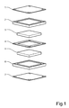
- the polymer electrolyte fuel cell structure according to the invention comprises a proton exchange membrane, an anode catalyst layer on one side of the proton exchange membrane, a cathode catalyst layer on the opposite side of the proton exchange membrane and a gas distribution layer on each side of the proton exchange membrane. It is characterized in that at least one of the gas distribution layers is a flat, porous structure having water channels formed in the surface facing the membrane, and that the gas distribution layer is enclosed by a coplanar, sealing plate with water inlet channels coupled to said water channels in the gas distribution layer.
- the fuel cell comprises a conductive anode plate 1.
- An anode sealing frame 2 is provided adjacent the bipolar plate 1.
- This frame is provided with a central, rectangular opening for an anode gas distribution layer 3.
- the frame 2 is also provided with an anode gas inlet 9 and an outlet 10 and distribution channels are formed as well as water inlets and outlets 11, 12 respectively.
- the anode gas distribution layer 3 is provided with a plurality of narrow water channels 3a on the opposite side of the layer 3, with reference to the anode plate 1.
- a proton exchange membrane 4 is arranged for cooperation with the plate 1 for sandwiching the frame 2 and the diffusion layer 3 between themselves.
- the cathode side of the fuel cell is structured in a similar manner as the anode side.
- the opposite side of the membrane 4 is arranged for cooperation with a conductive cathode plate 7 for sandwiching a cathode sealing frame 6 and a cathode gas distribution layer 5 between themselves.
- the cathode diffusion layer 5 is not provided with any water channels as the anode diffusion layer 3.
- the cathode sealing frame 6 is provided with a cathode gas inlet 13 and an outlet 14.
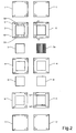
- figure 2 the detailed structure of water channels and how the water distribution is organized in a stack is shown.
- the left-hand side of the figure shows the upside and the right-hand side of the figure shows the down side.
- Each sealing frame 2 in a stack has a number of holes made through it.
- the holes located in the corners are for clamping bolts used when assembling a number of cell units to a cell stack.
- the remaining holes, together with corresponding holes in the other components of a stack, form channels through the stack for water, fuel gas and oxidant gas respectively.
- the upper side (as defined above) of the sealing 2 has gas channels 15 running along the inner edge of the frame like structure.
- a number of distribution apertures (in the figure there are five) are diverted from each channel 15, so as to distribute incoming gas into the diffusion/distribution material located in the frame.
- the second hole from left (in the figure) in the upper array of holes is the inlet channel 9 for incoming gas, and the second hole from left in the lower array of holes is the outlet channel 10 for gas exiting.from the cell on the anode side.
- the anode sealing 2 has the same configuration of gas channels regardless of position in the stack.
- each sealing 2 On the down side (as defined above) of each sealing 2 there are provided channels for water, having a common water inlet 11 and a common water outlet 12.
- the membrane 4 In the middle of the stack the membrane 4 is arranged, separating the anode and cathode parts of the stack.
- a cathode gas distribution layer 5 On the cathode side, a cathode gas distribution layer 5 is provided, and then there is sealing 6 for cathode wherein cathode gas inlet and outlet 13, 14 are formed, in a similar way as in the anode sealing 2.
- Figure 3 shows a more detailed structure of a gas distribution layer.
- the layer 3 is provided with water channels 3a adjacent the membrane 4.
- the water channels 3a may have a width of about 50-100 ⁇ m, a depth of about 100-300 ⁇ m and the channels may be separated by a distance of about 200-1000 ⁇ m.
- One possible method of producing the channels 3a would be to press the gas distribution layer against a template having a ridge structure surface corresponding to the desired water channel structure.
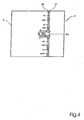
- Figure 4 shows an embodiment of the invention, where the gas distribution layer 3 is provided with a catalyst layer 16.
- a non-porous or almost non-porous proton conducting polymer layer 17 is arranged so that it lines the water channel.
- a hydrogen peroxide or other oxygen evolving compounds may be added to the humidification and cooling water, which is fed into the cell on the anode side. Since the oxygen is released in the vicinity of the catalyst, CO adsorption at the anode catalyst may be avoided, in a manner which is effective and which leads to less consumption of oxygen. Part of the hydrogen peroxide will be decomposed at the electrode surface to generate oxygen with the reaction H 2 O 2 - >H 2 O+1/2O 2 . In this system possible benefits of hydrogen peroxide are achieved even if the decomposition is not complete.
- the path of the hydrogen peroxide and evolved oxygen is marked as arrows in Fig. 4 . However, this method can be applied to other direct water humidification systems in polymer fuel cells.
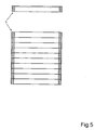
- Figure 5 shows a gas distribution layer 3, the edges of which has been treated with a hydrophobous polymer to prevent the water from entering the cell gas chamber.
- the gas distribution layers can have a porosity exceeding 90% and they should be good electrical conductors and have proper corrosion resistance against acid proton conducting membrane.
- each bipolar plate 1, 7 may be provided with an anode gas channel 19 and at least one water inlet 20.
- a water outlet 21 may also be provided.
- the cathode layer side of each bipolar plate is provided with at least one cathode gas channel 22.
- Fig. 7 An alternative structure for the water channels is presented in Fig. 7 .
- the catalyst layer 16 is located on top of the membrane 4.
- a hydrophobous layer 18 is positioned between the membrane and the gas distribution layer. The function of this layer 18 is to let gas diffuse to the electrode (catalyst layer) but not let the water to escape from the water channel 3a.
- the embodiment according to Fig. 7 may be used for operation of a liquid-gas direct methanol fuel cell.
- the anode side of the cell is fed with a liquid water-methanol mixture, which is totally or partially evaporated in the cell.
- the liquid mixture is fed in such a way that most part of the anode electrode is in contact with a thin film of liquid methanol-water mixture.
- the remaining area of the anode electrode is in contact with the gas phase free from liquid. This in order to enable both fast release of gaseous carbon dioxide as well as for humidifying the membrane by water vapor reactant to remaining part of the anode area.
- Water and methanol are transferred from fuel feeding channels to the anode electrode both directly and via gas phase. This is illustrated by means of arrows in Figure 7 .
- the above described method may also be applied to other types of fuel cell structures which are direct liquid cooled.
- the water channel structure is preferably applied to the anode side. However, this structure can also be applied to the cathode side or to both sides simultaneously.
Landscapes
- Chemical & Material Sciences (AREA)
- Life Sciences & Earth Sciences (AREA)
- Engineering & Computer Science (AREA)
- Manufacturing & Machinery (AREA)
- Sustainable Development (AREA)
- Sustainable Energy (AREA)
- Chemical Kinetics & Catalysis (AREA)
- Electrochemistry (AREA)
- General Chemical & Material Sciences (AREA)
- Composite Materials (AREA)
- Fuel Cell (AREA)
- Inert Electrodes (AREA)
Applications Claiming Priority (3)
| Application Number | Priority Date | Filing Date | Title |
|---|---|---|---|
| SE0002601A SE518621C2 (sv) | 2000-07-07 | 2000-07-07 | Struktur för en polymerbränslecell |
| SE0002601 | 2000-07-07 | ||
| PCT/SE2001/001514 WO2002005373A1 (en) | 2000-07-07 | 2001-06-29 | Polymer fuel cell structure |
Publications (2)
| Publication Number | Publication Date |
|---|---|
| EP1301956A1 EP1301956A1 (en) | 2003-04-16 |
| EP1301956B1 true EP1301956B1 (en) | 2012-08-01 |
Family
ID=20280439
Family Applications (1)
| Application Number | Title | Priority Date | Filing Date |
|---|---|---|---|
| EP01945875A Expired - Lifetime EP1301956B1 (en) | 2000-07-07 | 2001-06-29 | Polymer fuel cell structure |
Country Status (8)
| Country | Link |
|---|---|
| US (1) | US7790330B2 (enExample) |
| EP (1) | EP1301956B1 (enExample) |
| JP (1) | JP5111714B2 (enExample) |
| CN (1) | CN1235305C (enExample) |
| AU (1) | AU2001267984A1 (enExample) |
| CA (1) | CA2412180C (enExample) |
| SE (1) | SE518621C2 (enExample) |
| WO (1) | WO2002005373A1 (enExample) |
Families Citing this family (14)
| Publication number | Priority date | Publication date | Assignee | Title |
|---|---|---|---|---|
| US6663994B1 (en) | 2000-10-23 | 2003-12-16 | General Motors Corporation | Fuel cell with convoluted MEA |
| US7592089B2 (en) | 2000-08-31 | 2009-09-22 | Gm Global Technology Operations, Inc. | Fuel cell with variable porosity gas distribution layers |
| US6566004B1 (en) * | 2000-08-31 | 2003-05-20 | General Motors Corporation | Fuel cell with variable porosity gas distribution layers |
| GB2390738B (en) * | 2002-07-09 | 2005-05-11 | Intelligent Energy Ltd | Fuel cell direct water injection |
| US6838202B2 (en) | 2002-08-19 | 2005-01-04 | General Motors Corporation | Fuel cell bipolar plate having a conductive foam as a coolant layer |
| KR100519767B1 (ko) * | 2003-04-11 | 2005-10-10 | 삼성에스디아이 주식회사 | 센서를 구비하는 연료 전지의 연료량 공급 조절 시스템 |
| US20090169938A1 (en) * | 2004-03-30 | 2009-07-02 | Nissan Motor Co., Ltd. | Fuel cell apparatus |
| US20050221144A1 (en) * | 2004-03-30 | 2005-10-06 | Nissan Technical Center N.A. Inc. | Fuel cell apparatus |
| NL1026861C2 (nl) * | 2004-08-18 | 2006-02-24 | Stichting Energie | SOFC stackconcept. |
| US7601450B2 (en) * | 2005-03-23 | 2009-10-13 | Delphi Technologies, Inc. | Hybrid interconnect for a solid-oxide fuel cell stack |
| JP2007250351A (ja) * | 2006-03-16 | 2007-09-27 | Toyota Motor Corp | 燃料電池 |
| WO2008095533A1 (en) * | 2007-02-06 | 2008-08-14 | Nuvera Fuel Cells Europe Srl | Bipolar unit for fuel cell provided with porous current collectors |
| CN102903938A (zh) * | 2012-10-18 | 2013-01-30 | 西安交通大学 | 阴极采用非贵金属催化剂的高分子纤维膜甲醇燃料电池及制备方法 |
| JP2016091995A (ja) * | 2014-10-30 | 2016-05-23 | 株式会社デンソー | リチウム空気電池及びリチウム空気電池装置 |
Family Cites Families (10)
| Publication number | Priority date | Publication date | Assignee | Title |
|---|---|---|---|---|
| JPH05144444A (ja) * | 1991-11-25 | 1993-06-11 | Toshiba Corp | 燃料電池およびそれに用いる電極の製造方法 |
| JPH06338338A (ja) * | 1993-05-28 | 1994-12-06 | Mitsubishi Heavy Ind Ltd | 燃料電池の高分子イオン交換膜の加湿方法 |
| JP3203150B2 (ja) | 1995-05-18 | 2001-08-27 | 三洋電機株式会社 | 固体高分子型燃料電池及び固体高分子型燃料電池システム |
| US5879826A (en) * | 1995-07-05 | 1999-03-09 | Humboldt State University Foundation | Proton exchange membrane fuel cell |
| EP0996988A1 (en) * | 1997-05-13 | 2000-05-03 | Loughborough University Innovations Limited | Current distributors of sintered metals and fuel cells using them |
| US5935726A (en) | 1997-12-01 | 1999-08-10 | Ballard Power Systems Inc. | Method and apparatus for distributing water to an ion-exchange membrane in a fuel cell |
| US6007933A (en) * | 1998-04-27 | 1999-12-28 | Plug Power, L.L.C. | Fuel cell assembly unit for promoting fluid service and electrical conductivity |
| US6444346B1 (en) * | 1998-07-21 | 2002-09-03 | Matsushita Electric Industrial Co., Ltd. | Fuel cells stack |
| JP3022528B1 (ja) * | 1998-11-30 | 2000-03-21 | 三洋電機株式会社 | 固体高分子型燃料電池 |
| US6586128B1 (en) * | 2000-05-09 | 2003-07-01 | Ballard Power Systems, Inc. | Differential pressure fluid flow fields for fuel cells |
-
2000
- 2000-07-07 SE SE0002601A patent/SE518621C2/sv not_active IP Right Cessation
-
2001
- 2001-06-29 WO PCT/SE2001/001514 patent/WO2002005373A1/en not_active Ceased
- 2001-06-29 JP JP2002509127A patent/JP5111714B2/ja not_active Expired - Lifetime
- 2001-06-29 CN CNB018113664A patent/CN1235305C/zh not_active Expired - Lifetime
- 2001-06-29 AU AU2001267984A patent/AU2001267984A1/en not_active Abandoned
- 2001-06-29 CA CA2412180A patent/CA2412180C/en not_active Expired - Lifetime
- 2001-06-29 EP EP01945875A patent/EP1301956B1/en not_active Expired - Lifetime
-
2003
- 2003-01-07 US US10/248,304 patent/US7790330B2/en not_active Expired - Lifetime
Also Published As
| Publication number | Publication date |
|---|---|
| CA2412180A1 (en) | 2002-01-17 |
| CN1235305C (zh) | 2006-01-04 |
| US20030091887A1 (en) | 2003-05-15 |
| AU2001267984A1 (en) | 2002-01-21 |
| CA2412180C (en) | 2011-02-01 |
| SE518621C2 (sv) | 2002-10-29 |
| EP1301956A1 (en) | 2003-04-16 |
| CN1437776A (zh) | 2003-08-20 |
| JP5111714B2 (ja) | 2013-01-09 |
| JP2004503068A (ja) | 2004-01-29 |
| WO2002005373A1 (en) | 2002-01-17 |
| SE0002601L (sv) | 2002-01-08 |
| SE0002601D0 (sv) | 2000-07-07 |
| US7790330B2 (en) | 2010-09-07 |
Similar Documents
| Publication | Publication Date | Title |
|---|---|---|
| US5382478A (en) | Electrochemical fuel cell stack with humidification section located upstream from the electrochemically active section | |
| US5514487A (en) | Edge manifold assembly for an electrochemical fuel cell stack | |
| US6406807B1 (en) | Distribution of hydration fluid in a fuel cell | |
| Nguyen | A gas distributor design for proton‐exchange‐membrane fuel cells | |
| EP0664928B1 (en) | Lightweight fuel cell membrane electrode assembly with integral reactant flow passages | |
| US5773160A (en) | Electrochemical fuel cell stack with concurrent flow of coolant and oxidant streams and countercurrent flow of fuel and oxidant streams | |
| US5482680A (en) | Electrochemical fuel cell assembly with integral selective oxidizer | |
| US6207312B1 (en) | Self-humidifying fuel cell | |
| EP1134830B1 (en) | Monopolar cell pack of proton exchange membrane fuel cell and direct methanol fuel cell | |
| US6413664B1 (en) | Fuel cell separator plate with discrete fluid distribution features | |
| US20020192531A1 (en) | Liquid reactant flow field plates for liquid feed fuel cells | |
| EP1301956B1 (en) | Polymer fuel cell structure | |
| JP2007149694A (ja) | 反応体及び生成物の輸送を制御するための、平面内不均一構造を有する電極基板を備えた電気化学的燃料電池 | |
| US7201990B2 (en) | Fuel cell stack | |
| EP1294037B1 (en) | A fuel cell stack and a method of supplying reactant gases to the fuel cell stack | |
| US20060115705A1 (en) | Bipolar plate and direct liquid feed fuel cell stack | |
| US6969564B2 (en) | Fuel cell stack | |
| US7727660B2 (en) | Modified fuel cells with internal humidification and/or temperature control systems | |
| JPH06267562A (ja) | 固体高分子電解質燃料電池 | |
| KR20030091485A (ko) | 직접액체 연료 전지의 연료공급방법 및 이를 적용한직접액체연료 전지장치 | |
| JPH06338332A (ja) | 固体高分子電解質燃料電池用ガスセパレータ | |
| JP2003249243A (ja) | 燃料電池 | |
| CA2351871A1 (en) | Liquid reactant flow field plates for liquid feed fuel cells |
Legal Events
| Date | Code | Title | Description |
|---|---|---|---|
| PUAI | Public reference made under article 153(3) epc to a published international application that has entered the european phase |
Free format text: ORIGINAL CODE: 0009012 |
|
| 17P | Request for examination filed |
Effective date: 20030207 |
|
| AK | Designated contracting states |
Designated state(s): AT BE CH CY DE DK ES FI FR GB GR IE IT LI LU MC NL PT SE TR |
|
| AX | Request for extension of the european patent |
Extension state: AL LT LV MK RO SI |
|
| 17Q | First examination report despatched |
Effective date: 20100416 |
|
| RAP1 | Party data changed (applicant data changed or rights of an application transferred) |
Owner name: POWERCELL SWEDEN AB |
|
| GRAP | Despatch of communication of intention to grant a patent |
Free format text: ORIGINAL CODE: EPIDOSNIGR1 |
|
| GRAS | Grant fee paid |
Free format text: ORIGINAL CODE: EPIDOSNIGR3 |
|
| GRAA | (expected) grant |
Free format text: ORIGINAL CODE: 0009210 |
|
| AK | Designated contracting states |
Kind code of ref document: B1 Designated state(s): AT BE CH CY DE DK ES FI FR GB GR IE IT LI LU MC NL PT SE TR |
|
| REG | Reference to a national code |
Ref country code: GB Ref legal event code: FG4D |
|
| REG | Reference to a national code |
Ref country code: AT Ref legal event code: REF Ref document number: 569073 Country of ref document: AT Kind code of ref document: T Effective date: 20120815 Ref country code: CH Ref legal event code: EP |
|
| REG | Reference to a national code |
Ref country code: IE Ref legal event code: FG4D |
|
| REG | Reference to a national code |
Ref country code: DE Ref legal event code: R096 Ref document number: 60146909 Country of ref document: DE Effective date: 20120927 |
|
| REG | Reference to a national code |
Ref country code: NL Ref legal event code: VDEP Effective date: 20120801 |
|
| REG | Reference to a national code |
Ref country code: AT Ref legal event code: MK05 Ref document number: 569073 Country of ref document: AT Kind code of ref document: T Effective date: 20120801 |
|
| PG25 | Lapsed in a contracting state [announced via postgrant information from national office to epo] |
Ref country code: FI Free format text: LAPSE BECAUSE OF FAILURE TO SUBMIT A TRANSLATION OF THE DESCRIPTION OR TO PAY THE FEE WITHIN THE PRESCRIBED TIME-LIMIT Effective date: 20120801 Ref country code: AT Free format text: LAPSE BECAUSE OF FAILURE TO SUBMIT A TRANSLATION OF THE DESCRIPTION OR TO PAY THE FEE WITHIN THE PRESCRIBED TIME-LIMIT Effective date: 20120801 Ref country code: CY Free format text: LAPSE BECAUSE OF FAILURE TO SUBMIT A TRANSLATION OF THE DESCRIPTION OR TO PAY THE FEE WITHIN THE PRESCRIBED TIME-LIMIT Effective date: 20120801 |
|
| PG25 | Lapsed in a contracting state [announced via postgrant information from national office to epo] |
Ref country code: BE Free format text: LAPSE BECAUSE OF FAILURE TO SUBMIT A TRANSLATION OF THE DESCRIPTION OR TO PAY THE FEE WITHIN THE PRESCRIBED TIME-LIMIT Effective date: 20120801 Ref country code: PT Free format text: LAPSE BECAUSE OF FAILURE TO SUBMIT A TRANSLATION OF THE DESCRIPTION OR TO PAY THE FEE WITHIN THE PRESCRIBED TIME-LIMIT Effective date: 20121203 Ref country code: GR Free format text: LAPSE BECAUSE OF FAILURE TO SUBMIT A TRANSLATION OF THE DESCRIPTION OR TO PAY THE FEE WITHIN THE PRESCRIBED TIME-LIMIT Effective date: 20121102 Ref country code: SE Free format text: LAPSE BECAUSE OF FAILURE TO SUBMIT A TRANSLATION OF THE DESCRIPTION OR TO PAY THE FEE WITHIN THE PRESCRIBED TIME-LIMIT Effective date: 20120801 |
|
| PG25 | Lapsed in a contracting state [announced via postgrant information from national office to epo] |
Ref country code: NL Free format text: LAPSE BECAUSE OF FAILURE TO SUBMIT A TRANSLATION OF THE DESCRIPTION OR TO PAY THE FEE WITHIN THE PRESCRIBED TIME-LIMIT Effective date: 20120801 |
|
| PG25 | Lapsed in a contracting state [announced via postgrant information from national office to epo] |
Ref country code: DK Free format text: LAPSE BECAUSE OF FAILURE TO SUBMIT A TRANSLATION OF THE DESCRIPTION OR TO PAY THE FEE WITHIN THE PRESCRIBED TIME-LIMIT Effective date: 20120801 Ref country code: ES Free format text: LAPSE BECAUSE OF FAILURE TO SUBMIT A TRANSLATION OF THE DESCRIPTION OR TO PAY THE FEE WITHIN THE PRESCRIBED TIME-LIMIT Effective date: 20121112 |
|
| PG25 | Lapsed in a contracting state [announced via postgrant information from national office to epo] |
Ref country code: IT Free format text: LAPSE BECAUSE OF FAILURE TO SUBMIT A TRANSLATION OF THE DESCRIPTION OR TO PAY THE FEE WITHIN THE PRESCRIBED TIME-LIMIT Effective date: 20120801 |
|
| PLBE | No opposition filed within time limit |
Free format text: ORIGINAL CODE: 0009261 |
|
| STAA | Information on the status of an ep patent application or granted ep patent |
Free format text: STATUS: NO OPPOSITION FILED WITHIN TIME LIMIT |
|
| 26N | No opposition filed |
Effective date: 20130503 |
|
| REG | Reference to a national code |
Ref country code: DE Ref legal event code: R097 Ref document number: 60146909 Country of ref document: DE Effective date: 20130503 |
|
| PG25 | Lapsed in a contracting state [announced via postgrant information from national office to epo] |
Ref country code: MC Free format text: LAPSE BECAUSE OF FAILURE TO SUBMIT A TRANSLATION OF THE DESCRIPTION OR TO PAY THE FEE WITHIN THE PRESCRIBED TIME-LIMIT Effective date: 20120801 |
|
| REG | Reference to a national code |
Ref country code: CH Ref legal event code: PL |
|
| REG | Reference to a national code |
Ref country code: IE Ref legal event code: MM4A |
|
| PG25 | Lapsed in a contracting state [announced via postgrant information from national office to epo] |
Ref country code: CH Free format text: LAPSE BECAUSE OF NON-PAYMENT OF DUE FEES Effective date: 20130630 Ref country code: LI Free format text: LAPSE BECAUSE OF NON-PAYMENT OF DUE FEES Effective date: 20130630 Ref country code: IE Free format text: LAPSE BECAUSE OF NON-PAYMENT OF DUE FEES Effective date: 20130629 |
|
| PG25 | Lapsed in a contracting state [announced via postgrant information from national office to epo] |
Ref country code: TR Free format text: LAPSE BECAUSE OF FAILURE TO SUBMIT A TRANSLATION OF THE DESCRIPTION OR TO PAY THE FEE WITHIN THE PRESCRIBED TIME-LIMIT Effective date: 20120801 |
|
| PG25 | Lapsed in a contracting state [announced via postgrant information from national office to epo] |
Ref country code: LU Free format text: LAPSE BECAUSE OF NON-PAYMENT OF DUE FEES Effective date: 20130629 |
|
| REG | Reference to a national code |
Ref country code: FR Ref legal event code: PLFP Year of fee payment: 16 |
|
| REG | Reference to a national code |
Ref country code: FR Ref legal event code: PLFP Year of fee payment: 17 |
|
| REG | Reference to a national code |
Ref country code: FR Ref legal event code: PLFP Year of fee payment: 18 |
|
| PGFP | Annual fee paid to national office [announced via postgrant information from national office to epo] |
Ref country code: DE Payment date: 20200623 Year of fee payment: 20 Ref country code: FR Payment date: 20200623 Year of fee payment: 20 |
|
| PGFP | Annual fee paid to national office [announced via postgrant information from national office to epo] |
Ref country code: GB Payment date: 20200625 Year of fee payment: 20 |
|
| REG | Reference to a national code |
Ref country code: DE Ref legal event code: R071 Ref document number: 60146909 Country of ref document: DE |
|
| REG | Reference to a national code |
Ref country code: GB Ref legal event code: PE20 Expiry date: 20210628 |
|
| PG25 | Lapsed in a contracting state [announced via postgrant information from national office to epo] |
Ref country code: GB Free format text: LAPSE BECAUSE OF EXPIRATION OF PROTECTION Effective date: 20210628 |