EP1301129B1 - Chirurgische klammer - Google Patents
Chirurgische klammer Download PDFInfo
- Publication number
- EP1301129B1 EP1301129B1 EP01938537A EP01938537A EP1301129B1 EP 1301129 B1 EP1301129 B1 EP 1301129B1 EP 01938537 A EP01938537 A EP 01938537A EP 01938537 A EP01938537 A EP 01938537A EP 1301129 B1 EP1301129 B1 EP 1301129B1
- Authority
- EP
- European Patent Office
- Prior art keywords
- wire
- clip
- length
- temperature
- cutting element
- Prior art date
- Legal status (The legal status is an assumption and is not a legal conclusion. Google has not performed a legal analysis and makes no representation as to the accuracy of the status listed.)
- Expired - Lifetime
Links
Images


Classifications
-
- A—HUMAN NECESSITIES
- A61—MEDICAL OR VETERINARY SCIENCE; HYGIENE
- A61B—DIAGNOSIS; SURGERY; IDENTIFICATION
- A61B17/00—Surgical instruments, devices or methods, e.g. tourniquets
- A61B17/11—Surgical instruments, devices or methods, e.g. tourniquets for performing anastomosis; Buttons for anastomosis
- A61B17/1114—Surgical instruments, devices or methods, e.g. tourniquets for performing anastomosis; Buttons for anastomosis of the digestive tract, e.g. bowels or oesophagus
-
- A—HUMAN NECESSITIES
- A61—MEDICAL OR VETERINARY SCIENCE; HYGIENE
- A61B—DIAGNOSIS; SURGERY; IDENTIFICATION
- A61B17/00—Surgical instruments, devices or methods, e.g. tourniquets
- A61B17/12—Surgical instruments, devices or methods, e.g. tourniquets for ligaturing or otherwise compressing tubular parts of the body, e.g. blood vessels, umbilical cord
- A61B17/122—Clamps or clips, e.g. for the umbilical cord
- A61B17/1227—Spring clips
-
- A—HUMAN NECESSITIES
- A61—MEDICAL OR VETERINARY SCIENCE; HYGIENE
- A61B—DIAGNOSIS; SURGERY; IDENTIFICATION
- A61B17/00—Surgical instruments, devices or methods, e.g. tourniquets
- A61B2017/00831—Material properties
- A61B2017/00867—Material properties shape memory effect
-
- A—HUMAN NECESSITIES
- A61—MEDICAL OR VETERINARY SCIENCE; HYGIENE
- A61B—DIAGNOSIS; SURGERY; IDENTIFICATION
- A61B17/00—Surgical instruments, devices or methods, e.g. tourniquets
- A61B17/11—Surgical instruments, devices or methods, e.g. tourniquets for performing anastomosis; Buttons for anastomosis
- A61B2017/1139—Side-to-side connections, e.g. shunt or X-connections
Definitions
- the present invention relates to the field of surgical clips generally, and, in particular, to the field of surgical clips formed of a shape memory alloy.
- Staples for mechanical suturing ensure a reliable joining of tissue and enable the time needed for surgery to be reduced, compared with manual suturing.
- the price of staples is high.
- metal staples remain in place along the perimeter of the suture, which reduces elasticity of the junction and adversely affects peristalsis when the sutured organ is part of the gastrointestinal tract.
- junctions using compression devices ensure the best seal and post-operative functioning of the organs.
- Two types of compression devices are known, namely, rings made of resorption plastics and clips made of memory alloys. Plastic rings are cumbersome and expensive. Also, the compression force is applied only momentarily at the junction and is reduced as the tissue is crushed. Clips made of shape memory alloys enable portions of tissue to be pressed together when equilibrium with body temperature is reached, whereat, due to the inherent properties of the alloys, the clips resume their memorized shape.
- EP 0,326,757 discloses a device for anastomosing a digestive tract, which includes a plurality of U-shaped retaining clips disposed around a soluble support tube.
- the tube is positioned inside portions of the digestive tract to be joined, and includes an outer groove around which are disposed the U-shaped retaining clips.
- the retaining clips are made of a shape memory alloy such that the open ends thereof close at a predetermined temperature, thus joining ends of the digestive tract. Once the ends of the digestive tract have been joined, the tube is dissolved.
- Such a device is disadvantageous in that its use requires that a plurality of clips be properly positioned simultaneously. Also, there is no assurance that the resulting junction will be smooth, due to the plurality of sites of the digestive tract joined by the plurality of clips.
- SU 1,186,199 discloses a memory alloy clip consisting of two parallel coils to be used for joining portions of a hollow organ, such as an organ of the gastrointestinal tract.
- the portions of the organ to be joined are aligned, and each of the plastic coils is introduced through a puncture formed in the wall of one of the portions.
- the coils are positioned such that, when heated, they compress the aligned walls therebetween, thus maintaining the portions of the walls held within the loops of the coils adjacent to each other.
- incisions are made through the portions of the walls held within the loops of the coils, such that a passageway is created between the two organ portions.
- the punctures in the organ walls must then be surgically sewn closed with interrupted surgical sutures.
- Document WO 98/29040 discloses a surgical clip having three lengths of wire integrally formed of a shape memory alloy.
- a major disadvantage of known memory alloy clips is that they permit compression of only approximately 80-85% of the junction perimeter, thus requiring additional manual sutures, which reduce the seal of the junction during the healing period and its elasticity during the post-operative period. Also, this additional suturing is problematic inasmuch as it has to be carried out across a joint which includes a portion of the clip, thereby rendering difficult the sealing and anastomosis of the organ portions. Furthermore, once in place, clips according to the prior art require further surgery to be performed, namely, incisions through tissue so as to create a passageway between the two organ portions which have been joined by the clip.
- the present invention seeks to provide an improved surgical clip formed of a shape memory alloy, which overcome disadvantages of prior art.
- a surgical clip formed at least partly of a shape memory alloy including: a first length of a wire defining a closed geometrical shape having a central opening; a second length of a wire defining a closed geometrical shape similar in configuration and magnitude to that of the first length of wire, wherein, when placed in side-by-side registration, the first and second lengths of wire fully overlap; an intermediate portion located between the first length of wire and the second length of wire, the intermediate portion formed of a shape memory alloy; a cutting element associated with the first length of wire; and a counter element associated with the second length of wire and arranged for cutting engagement with the cutting element; wherein, when at a first temperature or higher, the first and second lengths of wire are positioned in a side-by-side closed position and the shape memory alloy is in an elastic state, and further, when at a second temperature or lower, below the first temperature, the shape memory alloy is in a plastic state, thereby enabling the first and
- the surgical clip further includes apparatus for pressing the cutting element into cutting engagement with the counter element wherein, when at the first temperature or higher, the apparatus for pressing presses the cutting element into cutting engagement with the counter element.
- the surgical clip further includes apparatus for pressing the cutting element into cutting engagement with the counter element wherein, when at the first temperature or higher, the apparatus for pressing is actuatable by an outside force.
- the geometrical shape of the surgical clip is a circle.
- the geometrical shape of the surgical clip is an ellipse.
- the first length of wire and the second length of wire are defined by a continuous coil.
- first length of wire and the second length of wire are two distinct lengths of wire, each defining a closed geometrical shape.
- the counter element also includes a cutting element.
- a method for anastomosing a gastrointestinal tract including the following steps: (a) providing a surgical clip formed at least partly of a shape memory alloy, the clip including: a first length of a wire defining a closed geometrical shape having a central opening; a second length of a wire defining a closed geometrical shape similar in configuration and magnitude to that of the first length of wire, wherein, when placed in side-by-side registration, the first and second lengths of wire fully overlap; an intermediate portion located between the first length of wire and the second length of wire, the intermediate portion formed of a shape memory alloy; a cutting element associated with the first length of wire; and a counter element associated with the second length of wire and arranged for cutting engagement with the cutting element; (b) cooling at least the intermediate portion to a temperature below a lower phase transition temperature thereof, whereat the intermediate portion is in a plastic state, thereby enabling the first and second lengths of wire to be moved into and to retain a spaced apart position; (c) manually moving apart
- the temperature of the clip is raised to the temperature above its upper phase transition temperature by the heat of the gastrointestinal tract.
- the clip further including apparatus for pressing the cutting element into cutting engagement with the counter element wherein, when at the upper phase transition temperature or higher, the apparatus for pressing presses the cutting element into cutting engagement with the counter element, thereby creating an opening in the tissue located between the first and second lengths of wire, thereby creating initial patency of the gastrointestinal tract; and the method includes after step (h), the additional step of widening the opening.
- the present invention seeks to provide a surgical clip, formed at least partly of a shape memory alloy, such as is known in the art, and which provides organ tissue compression along the entire periphery of the clip, thereby to ensure satisfactory joining or anastomosis of portions of an organ, and which provides apparatus for cutting a portion of tissue, whereby initial patency of the gastrointestinal tract is created.
- a shape memory alloy such as is known in the art
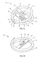
- Figs. 1A and 1B illustrate a surgical clip, referenced generally 10, according to a first embodiment of the present invention, the clip 10 shown in respective open and closed configurations.
- Clip 10 is typically wire-like, formed at least partly of a shape memory alloy, and is of a coiled configuration so as to include a pair of loops 12 and 22, having respective ends 14 and 24.
- Each of loops 12 and 22 defines a complete circle from its end to a point 30 midway along the coil.
- the coil defines two complete circles from end 14 of loop 12 to end 24 of loop 22.
- the various embodiments of the clip of the present invention are illustrated as defining circular shapes, it will be appreciated by persons skilled in the art that the present invention may, alternatively, define any closed geometric shape, such as an ellipse.
- At least an intermediate portion 13 of clip 10 is formed of a shape memory alloy such that, when cooled to below a predetermined temperature, the clip is in a plastic state, such that loops 12 and 22 may be moved apart, as to the position shown in Fig. 1A . When heated to above the predetermined temperature, the clip 10 is in an elastic state, such that the loops 12 and 22 are adjacent to each other, as in the position shown in Fig. 1B .
- the change in temperature, as it affects the shape memory alloy will be discussed further, with reference to Figs. 7A-D .
- Loops 12 and 22 of clip 10 are provided with a pair of crossbars 16 and 26, respectively, which extend across respective loops 12 and 22.
- Crossbars 16 and 26 may be fastened to respective loops 12 and 22 by any suitable means.
- Crossbar 16 is provided with an aperture 18, and crossbar 26 is provided with a hollow cutting element 20 having a blade portion 48 which circumscribes an aperture 28. Blade portion 48 of cutting element 20 has a configuration and size relative to aperture 18 so as to fit snugly therein ( Fig. 1B ).
- Crossbar 16 extends between points 32 and 34 along the circle defined by loop 12
- crossbar 26 extends between points 42 and 44 along the circle defined by loop 22. The distance along loop 12 from point 30 to point 32 is the same as the distance along loop 22 from end 24 to point 42.
- FIG. 1B when in the closed configuration, loops 12 and 22 are adjacent to each other, crossbars 16 and 26 are adjacent to each other, and cutting element 20 is positioned snugly within aperture 18.
- the crossbar 16 thus acts as a counter element for cutting element 20.
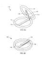
- a surgical clip referenced generally 110, according to a second embodiment of the present invention, the clip being in an open configuration and in a closed configuration, respectively.
- Clip 110 is similar to clip 10 ( Figs. 1A and 1B ) in that it defines a coil of two complete circles, including an intermediate portion 113 formed of a shape.memory alloy, but clip 110 is provided with a crossbar 116 and bar 126 on respective loops 12 and 22. Crossbar 116 and bar 126 may be fastened to respective loops 12 and 22 by any suitable means.
- Bar 126 is also provided with a surgical blade 128 which extends out of bar 126 such that, when the clip 110 is in the closed configuration, blade 128 presses against crossbar 116 ( Fig. 2B ).
- crossbar 116 acts as a counter element for blade 128.
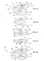
- Figs. 3A-3D illustrate a surgical clip, referenced generally 130, according to a third embodiment of the present invention.
- Clip 130 includes an intermediate portion 13 formed of a shape memory alloy and defines a coil of two complete circles, as does clip 10, and has similar loops 12 and 22.
- loop 22 of clip 130 is provided with a cutting element 133 in the form of an L-shaped arm 132 having a blade 134 at its end which extends towards the center of loop 22.
- Loop 12 is provided with a counter element 136 in the form of an arm 137 having a U-shaped portion 138 at its end, the open end of the U facing towards the center of loop 12.
- L-shaped element 132 and counter element 136 may be fastened to respective loops 22 and 12 by any suitable means. It will be appreciated by persons skilled in the art that cutting element 133 and element 136 may be configured as having any other suitable shapes whereby they will function as a cutting element and counter element for the purposes of the present invention.
- Figs. 3A and 3B show clip 130 with intermediate portion 13 in a plastic state, wherein the loops 12 and 22 have been moved apart.
- intermediate portion 13 is in an elastic state, as shown in Figs. 3C and 3D , loops 12 and 22 are pressed against each other.
- blade 134 of cutting element 133 is positioned adjacent to, yet apart from, U-shaped portion 138 of counter element 136.
- After release of cutting element 133 and counter element 136 these elements are allowed to return to their positions shown in Fig. 3C .
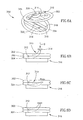
- Figs. 4A, 4B, 4C, and 4D illustrate a surgical clip, referenced generally 140, according to a fourth embodiment of the present invention.
- Clip 140 includes two ring portions 142 and 144, which are attached at an intermediate portion 150. While, if desired, the entire clip 140 may be formed of a shape memory alloy, it is essential that at least the intermediate portion 150 be formed of a shape memory alloy.
- Ring portions 142 and 144 are provided with respective crossbars 146 and 148.
- At the center of crossbar 146 there is provided a cutting element 152 which is slidably attached therethrough.
- Cutting element 152 includes a ringshaped head portion 156 and a cylindrical portion 158 having an aperture 159.
- Crossbar 148 is provided with a counter element 162 in the form of a cylindrical aperture 154, of size and configuration similar to that of cylindrical portion 158 of cutting element 152, and of a flange portion 160 ( Figs. 4B, 4C, 4D ), positioned about aperture 154 on the side of crossbar 148 which is distal to crossbar 146.
- cutting element 152 and counter element 162 of clip 140 are shown as having a particular size and shape, it will be appreciated by persons skilled in the art that any suitable configuration of cutting element and counter element may be employed, whereby tissue located therebetween may be sliced or cut out.
- intermediate portion 150 of clip 140 is shown in its plastic state, wherein ring portions 142 and 144 have been moved apart.
- intermediate portion 150 of the clip 140 is in an elastic state, as shown in Figs. 4C and 4D , ring portions 142 and 144 are firmly pressed against each other, and cylindrical portion 158 of cutting element 152 is positioned adjacent to aperture 154 of counter element 162.
- head portion 156 of cutting element 152 on crossbar 146 in the direction of arrow B, and to flange portion 160 of counter element 162, in the direction of arrow C, cylindrical portion 158 is forced into aperture 154 ( Fig. 4D ), where it is held in position by the snug fit between cylindrical portion 158 and the inner surface of aperture 154.
- Fig. 4E illustrates a surgical clip according to a fifth embodiment of the present invention.
- Clip 170 is similar to clip 140 ( Figs. 4A, 4B, 4C and 4D ) in that it includes an intermediate portion I50 formed of a shape memory alloy and is provided with ring portions 142 and 144.
- ring portions 142 and 144 are provided with respective arms 172 and 174 which extend from corresponding points along ring portions 142 and 144 into the interior thereof.
- Arms 172 and 174 may be fastened to respective ring portions 142 and 144 by any suitable means.
- On the end of arm 172 there is formed a cutting element 176 having a head portion 178 and a cylindrical portion 180 having an aperture 181.
- the end of arm 174 is provided with a counter element 186 having a cylindrical portion 182 and a cylindrical aperture 184 of size and configuration similar to that of cylindrical portion 180 of cutting element 176.
- intermediate portion 150 of clip 170 is shown in a plastic state, wherein the ring portions 142 and 144 have been moved apart.
- intermediate portion 150 of clip 170 is in an elastic state (not shown)
- ring portions 142 and 144 are firmly pressed against each other, and cylindrical portion 180 of cutting element 176 is positioned adjacent to aperture 184 of counter element 186.
- head portion 178 of cutting element 176 on arm 172 and to cylindrical portion 182 of counter element 186 cylindrical portion 180 of cutting element 176 is forced into aperture 184, where it is held in position by the snug fit between cylindrical portion 180 and the inner surface of aperture 184.
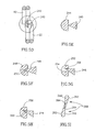
- FIG. 5A and 5B are pictorial illustrations of a counter element, referenced generally 200, and of a cutting element, referenced generally 210, which may be employed in the surgical clip 170 shown in Fig. 4E .
- Counter element 200 is provided with an X-shaped aperture 202 which corresponds in configuration and size to blade 212 of cutting element 210.
- X-shaped aperture 202 which corresponds in configuration and size to blade 212 of cutting element 210.
- FIG. 5C shows a cutting element 220 and a corresponding counter element 230 which may be employed in the surgical clip according to either of Figs. 1A and 1B .
- Cutting element 220 is provided with an elliptically shaped base portion 222 having a pair of needle-like blades 224 protruding therefrom.
- Counter element 230 is provided with an elliptically shaped base portion 232, similar in configuration and size to base portion 222 of cutting element 220, and a flange 234 extending therefrom.
- Base portion 232 also has an elliptical aperture 236, whose width is similar to that of blades 224 and whose length is at least equal to the distance between the outer edge of one blade to the outer edge of the other blade.
- Figs. 5D, 5E, 5F, 5G, 5H, and 5I illustrate several particular examples of the relationship between specific blade element and counter element combinations, which may replace the blade elements and counter elements employed in the embodiments of the present invention shown in Figs. 2-4 .
- Fig. 5D when the shape memory alloy of the device is in an elastic state, loops 12 and 22 are pressed against each other.
- Figs. 5D and 5E show blade 240 when it has made contact with each of the flat-surfaced counter elements 242 and 244.
- Fig. 5F there are shown a blade 240 and a counter element 248 having a recess 250 shaped to accommodate the tip of blade 240.
- FIG. 5G shows a blade 246 and a counter element 252 having a cylindrical recess 254 extending therethrough.
- Recess 254 is large enough to receive the tip 256 of blade 246.
- a counter element 258 having a triangular recess 260 shaped to accommodate the tip of blade 246.
- FIG. 5I shows an alternative embodiment, wherein the blade element and counter element combination has been replaced by a pair of blade elements 268 in the form of blades 262 which come into contact, when loops 12 and 22 ( Fig. 5D ) are pressed against each other, such that the tip 264 of each blade 262 lies along a side 266 of the other blade 262.
- Figs. 6A-6D show a surgical clip 300 according to a sixth embodiment of the present invention.
- Clip 300 includes two ring portions 302 and 304, which are attached at an intermediate portion 306 formed of a shape memory alloy.
- Ring portion 302 is provided with an off-center crossbar 308 having a rotatable blade element 310 thereon.
- Cutting element 310 includes a blade 312 and a head portion 314 by means of which the blade 312 may be rotated downward toward the center of ring portion 302.
- Across the center of ring 304 there is provided a counter element 316 configured as a pair of parallel bars 318 having a generally rectangular gap 320 therebetween. Bars 318 are positioned such that gap 320 is wide enough to accommodate blade 312, yet narrow enough to provide a snug fit therefor.
- counter element 316 may be replaced by any other counter element suitable for use with cutting blade 312.
- ring portions 302 and 304 When intermediate portion 306 is in a plastic state, ring portions 302 and 304 may be moved apart, to the position shown in Fig. 6A .
- intermediate portion 306 of the clip 300 When, however, as shown in Figs. 6B-6D , intermediate portion 306 of the clip 300 is in an elastic state, ring portions 302 and 304 are firmly pressed against each other.
- FIG. 6B by applying pressure in the general direction of arrow D to head portion 314 of cutting element 310, blade 312 is rotated about crossbar 308, such that it moves downward. This will result in the cutting element 310 being in the position shown in Fig. 6C , wherein blade 312 is snugly fit within gap 320 of counter element 316.
- the cutting element 310 may be provided with biasing or similar means (not shown), whereby the blade 312 is pulled or pushed out of gap 320 so that it is automatically returned to its upper position, as shown in Fig. 6D .
- FIGs. 7A-7D there are shown portions 52 and 54 of a hollow organ 50, which it is desired to join together by anastomosis.
- Hollow organ 50 may be a colon, or any other hollow organ which requires anastomosis.
- the method which is disclosed here may be employed for the connection of a portion of a first hollow organ to a second hollow organ, such as the connection of a colon portion to a stomach. The method will now be described with reference to clip 10. However, it will be appreciated by persons skilled in the art that the method may be carried out by utilizing any embodiment of the clip, or by employing any of the elements described above.
- a device employing a shape memory alloy such as a clip according to the present invention, may be described as being of one of two different types.
- a first type of device employs a shape memory alloy which is in an easily deformable, martensitic state when it is cooled to below room temperature, which achieves a fully or partial austenitic state at room temperature, and which is in a completely austenitic state when heated to at least its upper phase transition temperature, which is somewhere between room temperature and body temperature.
- the shape memory alloy is in an easily deformable, martensitic state at room temperature, whereat the device is deformed and applied, and the shape memory alloy achieves a completely austenitic state when heated to above room temperature.
- the difference between the two types of devices is in the temperature range at which the shape memory alloy is easily deformable.
- At least the shape memory alloy portion 13 of clip 10 is cooled to at least its lower phase transition temperature, whereat the shape memory alloy is in its martensitic state, as known in the art, the at least intermediate portion 13 of clip 10 thus being in a plastic state.
- the lower phase transition temperature may be generally any temperature above -273°C, although more generally it is approximately 25-35°C below body temperature, preferably approximately 0°C. Loops 12 and 22 are manually moved apart a desired distance and clip 10 is preserved in the cooled state for as long as required until insertion into the organ 50.
- Open ends 56 and 58 of separate organ portions 52 and 54 are surgically stapled or sewn closed, as by sutures 72, thereby resulting in separate closed ends 56A and 58A.
- Portions 52 and 54 of organ 50 are drawn together in an adjacent, side-by-side relationship, and adjacent walls 60 and 62 are perforated at punctures 64 and 66, respectively, the punctures 64 and 66 being adjacent.
- the size and shape of punctures 64 and 66 are chosen as desired, so as to be able to facilitate positioning of loops 12 and 22 inside respective organ portions 52 and 54.
- Clip 10 is introduced into organ portions 52 and 54 by inserting loops 12 and 22 via punctures 64 and 66, respectively, such that loops 12 and 22 are situated inside organ portions 52 and 54, so as to straddle respective walls 60 and 62. While the method is described herein in relation to Figs. 7A-7D , wherein both organ portions 52 and 54 are first surgically stapled or sewn closed, it will be understood by persons skilled in the art that either one or both of the organ portions 52 and 54 may be sewn closed after insertion of the surgical clip,.
- tissue portions 52 and 54 of organ 50 and the relative position of clip 10 in relation thereto must be maintained for a period of time during which the temperature of organ 50 is effective to cause the temperature of the intermediate portion 13 of the clip 10 to rise to a temperature at least equal to its upper phase transition temperature, whereat the clip 10 achieves its austenitic state, which is, preferably, below body temperature.
- the temperature of the intermediate portion 13 of the clip 10 rises towards its transition temperature, loops 12 and 22 continue to converge and to press the tissue portions 68 and 70 of organ walls 60 and 62 located therebetween more and more tightly against each other.
- Tissue portions 68 and 70 are defined by the portions of respective walls 60 and 62 located between loops 12 and 22.
- each of tissue portions 68 and 70 is configured as an area similar in shape and size to the loops 12 and 22 of clip 10.
- the rate by which the temperature of intermediate portion 13 of clip 10 rises may be accelerated by heating clip 10, for example, by any method known in the art.
- clip 10 has returned to its elastic phase, as shown in Figs. 7C and 7D , wherein loops 12 and 22 are pressing against each other, and thus are maintaining walls 60 and 62 in a fixed position relative to each other.
- blade 48 of cutting element 20 is being pressed into aperture 18, thus slicing out a portion of tissue portions 68 and 70 which is similar in size and shape to that of blade 48. This slicing out of a portion of the tissue will create initial patency of the gastrointestinal tract.
- tissue portions 68 and 70 Due to the pressure exerted by clip 10 on walls 60 and 62 of organ 50, respective tissue portions 68 and 70 are pressed so tightly against each other that blood flow to these tissue portions ceases, resulting in eventual necrosis of these tissue portions 68 and 70.
- tissue portions 68 and 70 die the tissue portions 68A and 70A immediately thereoutside mend together such that portions 52 and 54 of organ 50 are joined, and organ 50 may function as one continuous organ.
- tissue portions 68 and 70 die they, together with clip 10, become separated from walls 60 and 62, resulting in a hole 74 ( Fig. 7C ).
- Dead tissue portions 68 and 70, together with clip 10 are passed out of organ 50, via hole 74, by the normal activity of the organ. For example, if organ 50 is the small intestine, and the direction of peristalsis is from portion 52 towards portion 54, then clip 10 and tissue portions 68 and 70 will be passed through portion 54 by the normal activity of the small intestine.
- either of clips 140 ( Figs. 4A-4D ) and 170 ( Fig. 4E ) may be employed instead of employing clip 10 in the surgical procedure as discussed above, and as illustrated in Figs. 7A-7D .
- clips 140 ( Figs. 4A-4D ) and 170 ( Fig. 4E ) may be employed instead of employing clip 10 in the surgical procedure as discussed above, and as illustrated in Figs. 7A-7D .
- the use of either of these embodiments of the present invention would require that, after a clip (140, 170) has been introduced into the organ 50 and the intermediate portion thereof has attained its elastic (martensitic) state, as discussed above, the respective cutting element (152, 176) and counter element (162, 186) would have to be manually forced into cutting engagement.
- any of clips 110 ( Figs. 2A and 2B ), 130 ( Figs. 3A-3D ), and 300 ( Figs. 6A-6D ) may be employed in the surgical procedure discussed above.
- the use of clip 110 would enable the blade 128 and crossbar 116 to automatically make an incision through the portions of the tissue located therebetween, as the blade 128 is forced into cutting engagement with the crossbar 116 when the clip 110 is in an elastic state, as discussed above with regard to Figs. 2A and 2B .
- clips 130 and 300 would require that, after the clip (130, 300) has been introduced into the organ 50 and has attained its elastic state, as discussed above, the respective cutting element (133, 310) and counter element (136, 316) would have to be manually forced into cutting engagement. This would cause the cutting element (133, 310), together with the counter element (136, 316), to make an incision through the portions of the tissue located therebetween. This incision through a portion of the tissue will create initial patency of the gastrointestinal tract. If desired, after an incision has been made by any of the clips (110, 130, 300), the incision may be widened somewhat, although should not be widened to the entire area of the tissue portions 68 and 70.
Landscapes
- Health & Medical Sciences (AREA)
- Surgery (AREA)
- Life Sciences & Earth Sciences (AREA)
- Animal Behavior & Ethology (AREA)
- Public Health (AREA)
- Engineering & Computer Science (AREA)
- Biomedical Technology (AREA)
- Heart & Thoracic Surgery (AREA)
- Medical Informatics (AREA)
- Molecular Biology (AREA)
- Veterinary Medicine (AREA)
- General Health & Medical Sciences (AREA)
- Nuclear Medicine, Radiotherapy & Molecular Imaging (AREA)
- Physiology (AREA)
- Reproductive Health (AREA)
- Vascular Medicine (AREA)
- Surgical Instruments (AREA)
- Materials For Medical Uses (AREA)
- Prostheses (AREA)
- Pharmaceuticals Containing Other Organic And Inorganic Compounds (AREA)
- Gripping Jigs, Holding Jigs, And Positioning Jigs (AREA)
Claims (8)
- Chirurgische Klammer (10), die zumindest teilweise aus einer Formgedächtnislegierung geformt ist, wobei die Klammer Folgendes aufweist: ein erstes Stück eines Drahts (22), das eine geschlossene geometrische Form mit einer mittigen Öffnung definiert; ein zweites Stück eines Drahts (12), das eine geschlossene geometrische Form definiert, die in Konfiguration und Größenordnung der Form des ersten Stücks Draht ähnlich ist, worin sich die ersten und zweiten Stücke Draht, wenn sie Seite an Seite gelegt werden, vollständig überlappen; einen Zwischenabschnitt (13) zwischen dem ersten Stück Draht und dem zweiten Stück Draht, wobei der Zwischenabschnitt aus einer Formgedächtnislegierung geformt ist; ein Schneidelement (48), das mit dem ersten Stück Draht (22) in Verbindung steht; und ein Zählelement (16), das mit dem zweiten Stück Draht (12) in Verbindung steht und so angeordnet ist, dass es mit dem Schneidelement in Schneideingriff geraten kann; worin bei einer ersten Temperatur oder höher die ersten und zweiten Stücke Draht in einer Seite an Seite liegenden geschlossenen Position liegen und sich die Formgedächtnislegierung in einem elastischen Zustand befindet und worin sich ferner bei einer zweiten Temperatur oder einer unter der ersten Temperatur liegenden, niedrigeren Temperatur die Formgedächtnislegierung in einem plastischen Zustand befindet, wodurch die ersten und zweiten Stücke Draht in eine beabstandete Position bewegt und dort gehalten werden können und worin nach dem Erwärmen der Klammer auf eine Temperatur, die der ersten Temperatur zumindest gleich ist, die ersten und zweiten Stücke Draht wieder in ihre Seite an Seite liegende geschlossene Position zurückkehren, so dass eine Kompressionskraft auf das dazwischenliegende Gewebe ausgeübt wird.
- Chirurgische Klammer nach Anspruch 1, die ferner ein Gerät zum Drücken des Schneidelements in Schneideingriff mit dem Zählelement umfasst, worin das Gerät zum Drücken bei der ersten Temperatur oder höher das Schneidelement in Schneideingriff mit dem Zählelement drückt.
- Chirurgische Klammer nach Anspruch 1, die ferner ein Gerät zum Drücken des Schneidelements in Schneideingriff mit dem Zählelement umfasst, worin das Gerät zum Drücken bei der ersten Temperatur oder höher von einer externen Kraft betätigt werden kann.
- Chirurgische Klammer nach Anspruch 1, worin die geometrische Form ein Kreis ist.
- Chirurgische Klammer nach Anspruch 1, worin die geometrische Form eine Ellipse ist.
- Chirurgische Klammer nach Anspruch 1, worin das erste Stück Draht und das zweite Stück Draht von einer kontinuierlichen Spule geformt werden.
- Chirurgische Klammer nach Anspruch 1, worin das erste Stück Draht und das zweite Stück Draht zwei getrennte Stücke Draht sind, die jeweils eine geschlossene geometrische Form entschärfen.
- Chirurgische Klammer nach Anspruch 1, worin das Zählelement auch ein Schneidelement aufweist.
Applications Claiming Priority (3)
| Application Number | Priority Date | Filing Date | Title |
|---|---|---|---|
| IL13670200A IL136702A (en) | 2000-06-12 | 2000-06-12 | Surgical clip |
| IL13670200 | 2000-06-12 | ||
| PCT/IL2001/000525 WO2001095783A2 (en) | 2000-06-12 | 2001-06-07 | Surgical clip |
Publications (3)
| Publication Number | Publication Date |
|---|---|
| EP1301129A2 EP1301129A2 (de) | 2003-04-16 |
| EP1301129A4 EP1301129A4 (de) | 2008-10-22 |
| EP1301129B1 true EP1301129B1 (de) | 2009-09-02 |
Family
ID=11074254
Family Applications (1)
| Application Number | Title | Priority Date | Filing Date |
|---|---|---|---|
| EP01938537A Expired - Lifetime EP1301129B1 (de) | 2000-06-12 | 2001-06-07 | Chirurgische klammer |
Country Status (6)
| Country | Link |
|---|---|
| EP (1) | EP1301129B1 (de) |
| JP (1) | JP3742386B2 (de) |
| CN (1) | CN1232228C (de) |
| AT (1) | ATE441365T1 (de) |
| CA (1) | CA2411530C (de) |
| DE (1) | DE60139782D1 (de) |
Cited By (3)
| Publication number | Priority date | Publication date | Assignee | Title |
|---|---|---|---|---|
| US10154844B2 (en) | 2016-07-25 | 2018-12-18 | Virender K. Sharma | Magnetic anastomosis device and delivery system |
| US10561423B2 (en) | 2016-07-25 | 2020-02-18 | Virender K. Sharma | Cardiac shunt device and delivery system |
| US11304698B2 (en) | 2016-07-25 | 2022-04-19 | Virender K. Sharma | Cardiac shunt device and delivery system |
Families Citing this family (10)
| Publication number | Priority date | Publication date | Assignee | Title |
|---|---|---|---|---|
| ES2271220T3 (es) | 2001-02-23 | 2007-04-16 | Refocus Ocular, Inc. | Sistema para hacer incisiones para implantes oculares en la esclerotica. |
| US20070088412A1 (en) * | 2005-10-13 | 2007-04-19 | Intelifuse, Inc., A Corporation Of The State Of Delaware | System and device for heating or cooling shape memory surgical devices |
| US8083759B2 (en) | 2007-11-02 | 2011-12-27 | Refocus Ocular, Inc. | Apparatuses and methods for forming incisions in ocular tissue |
| EP2330965B1 (de) * | 2008-09-05 | 2018-07-11 | Carnegie Mellon University | Endoskopische multilink-vorrichtung mit sphärischer distaler anordnung |
| KR101604080B1 (ko) | 2009-07-21 | 2016-03-17 | 삼성전자주식회사 | 혈관 가압 커프, 상기 혈관 가압 커프를 구비한 혈압 측정 장치, 및 상기 혈압 측정 장치를 이용한 혈압 측정 방법 |
| WO2011112888A2 (en) * | 2010-03-11 | 2011-09-15 | Microkoll, Inc. | Apparatus and method for tissue adhesion |
| US8597318B2 (en) | 2011-08-08 | 2013-12-03 | Refocus Group, Inc. | Apparatus and method for forming incisions in ocular tissue |
| JP6752816B2 (ja) * | 2015-12-18 | 2020-09-09 | 株式会社カネカ | 接続具、医療用クリップ装置および医療用クリップ装置の製造方法 |
| US10555725B2 (en) | 2016-09-29 | 2020-02-11 | Gyrus Acmi, Inc. | Thermal mechanism to prevent reprocessing or reuse of mechanical surgical devices |
| MX2020002058A (es) | 2017-08-23 | 2020-07-13 | Refocus Group Inc | Herramienta quirurgica para formar incisiones en el tejido ocular con una punta que proporciona visibilidad y aparato y metodo relacionados. |
Family Cites Families (5)
| Publication number | Priority date | Publication date | Assignee | Title |
|---|---|---|---|---|
| US5222963A (en) * | 1991-01-17 | 1993-06-29 | Ethicon, Inc. | Pull-through circular anastomosic intraluminal stapler with absorbable fastener means |
| US5171252A (en) * | 1991-02-05 | 1992-12-15 | Friedland Thomas W | Surgical fastening clip formed of a shape memory alloy, a method of making such a clip and a method of using such a clip |
| US5591173A (en) * | 1994-07-28 | 1997-01-07 | Michael Schifano | Schifano obstetric scissors |
| IL119911A (en) * | 1996-12-25 | 2001-03-19 | Niti Alloys Tech Ltd | Surgical clip |
| IL132635A0 (en) * | 1999-10-28 | 2001-03-19 | Niti Alloys Tech Ltd | Shape memory alloy clip and method of use thereof |
-
2001
- 2001-06-07 EP EP01938537A patent/EP1301129B1/de not_active Expired - Lifetime
- 2001-06-07 CN CNB018109497A patent/CN1232228C/zh not_active Expired - Fee Related
- 2001-06-07 CA CA002411530A patent/CA2411530C/en not_active Expired - Fee Related
- 2001-06-07 DE DE60139782T patent/DE60139782D1/de not_active Expired - Lifetime
- 2001-06-07 AT AT01938537T patent/ATE441365T1/de not_active IP Right Cessation
- 2001-06-07 JP JP2002509972A patent/JP3742386B2/ja not_active Expired - Fee Related
Cited By (3)
| Publication number | Priority date | Publication date | Assignee | Title |
|---|---|---|---|---|
| US10154844B2 (en) | 2016-07-25 | 2018-12-18 | Virender K. Sharma | Magnetic anastomosis device and delivery system |
| US10561423B2 (en) | 2016-07-25 | 2020-02-18 | Virender K. Sharma | Cardiac shunt device and delivery system |
| US11304698B2 (en) | 2016-07-25 | 2022-04-19 | Virender K. Sharma | Cardiac shunt device and delivery system |
Also Published As
| Publication number | Publication date |
|---|---|
| JP2004503276A (ja) | 2004-02-05 |
| CN1436060A (zh) | 2003-08-13 |
| CA2411530A1 (en) | 2001-12-20 |
| CA2411530C (en) | 2009-07-28 |
| JP3742386B2 (ja) | 2006-02-01 |
| ATE441365T1 (de) | 2009-09-15 |
| EP1301129A4 (de) | 2008-10-22 |
| DE60139782D1 (de) | 2009-10-15 |
| CN1232228C (zh) | 2005-12-21 |
| EP1301129A2 (de) | 2003-04-16 |
Similar Documents
| Publication | Publication Date | Title |
|---|---|---|
| US6402765B1 (en) | Surgical clip | |
| EP1009293B1 (de) | Chirurgische klammer | |
| EP1289428B1 (de) | Klip aus formgedächtnislegierung und verfahren zu dessen verwendung | |
| EP1301129B1 (de) | Chirurgische klammer | |
| US5752966A (en) | Exovascular anastomotic device | |
| AU2003235991B2 (en) | Surgical clip applicator device | |
| AU593581B2 (en) | Surgical clip, applier, and method | |
| US8205782B2 (en) | Compression assemblies and applicators for use therewith | |
| US7527185B2 (en) | Compression anastomosis ring assembly and applicator for use therewith | |
| US5989268A (en) | Endoscopic hemostatic clipping device | |
| US4787386A (en) | Anastomosis devices, and kits | |
| US5817113A (en) | Devices and methods for performing a vascular anastomosis | |
| EP0158316A2 (de) | Vorrichtungen und Austrüstung für die anastomotische Chirurgie | |
| US6699257B2 (en) | Devices and methods for performing a vascular anastomosis | |
| IL150855A (en) | Intratubular anastomosis apparatus | |
| US4771775A (en) | Anastomosis devices, kits and method | |
| AU2003245013B2 (en) | Anastomosis ring applier | |
| CN106419986B (zh) | 一种外翻式环形吻合器 | |
| WO2005027736A2 (en) | Devices and methods for forming magnetic anastomoses between vessels | |
| AU751430B2 (en) | Devices and methods for performing a vascular anastomosis | |
| JP2002301083A (ja) | 血管吻合器具 | |
| EP1174089A1 (de) | Verbindungsvorrichtung zur ausführung von vaskulären Anastomosen |
Legal Events
| Date | Code | Title | Description |
|---|---|---|---|
| PUAI | Public reference made under article 153(3) epc to a published international application that has entered the european phase |
Free format text: ORIGINAL CODE: 0009012 |
|
| 17P | Request for examination filed |
Effective date: 20030113 |
|
| AK | Designated contracting states |
Designated state(s): AT BE CH CY DE DK ES FI FR GB GR IE IT LI LU MC NL PT SE TR |
|
| AX | Request for extension of the european patent |
Extension state: AL LT LV MK RO SI |
|
| RAP1 | Party data changed (applicant data changed or rights of an application transferred) |
Owner name: NITI MEDICAL TECHNOLOGIES LTD. |
|
| A4 | Supplementary search report drawn up and despatched |
Effective date: 20080919 |
|
| RIC1 | Information provided on ipc code assigned before grant |
Ipc: A61B 17/00 20060101ALN20080915BHEP Ipc: A61B 17/122 20060101ALI20080915BHEP Ipc: A61B 17/11 20060101AFI20020516BHEP |
|
| GRAP | Despatch of communication of intention to grant a patent |
Free format text: ORIGINAL CODE: EPIDOSNIGR1 |
|
| GRAS | Grant fee paid |
Free format text: ORIGINAL CODE: EPIDOSNIGR3 |
|
| GRAA | (expected) grant |
Free format text: ORIGINAL CODE: 0009210 |
|
| RAP1 | Party data changed (applicant data changed or rights of an application transferred) |
Owner name: NITI SURGICAL SOLUTIONS LTD. |
|
| AK | Designated contracting states |
Kind code of ref document: B1 Designated state(s): AT BE CH CY DE DK ES FI FR GB GR IE IT LI LU MC NL PT SE TR |
|
| REG | Reference to a national code |
Ref country code: CH Ref legal event code: EP |
|
| REG | Reference to a national code |
Ref country code: IE Ref legal event code: FG4D |
|
| REF | Corresponds to: |
Ref document number: 60139782 Country of ref document: DE Date of ref document: 20091015 Kind code of ref document: P |
|
| PG25 | Lapsed in a contracting state [announced via postgrant information from national office to epo] |
Ref country code: SE Free format text: LAPSE BECAUSE OF FAILURE TO SUBMIT A TRANSLATION OF THE DESCRIPTION OR TO PAY THE FEE WITHIN THE PRESCRIBED TIME-LIMIT Effective date: 20090902 Ref country code: FI Free format text: LAPSE BECAUSE OF FAILURE TO SUBMIT A TRANSLATION OF THE DESCRIPTION OR TO PAY THE FEE WITHIN THE PRESCRIBED TIME-LIMIT Effective date: 20090902 |
|
| NLV1 | Nl: lapsed or annulled due to failure to fulfill the requirements of art. 29p and 29m of the patents act | ||
| PG25 | Lapsed in a contracting state [announced via postgrant information from national office to epo] |
Ref country code: NL Free format text: LAPSE BECAUSE OF FAILURE TO SUBMIT A TRANSLATION OF THE DESCRIPTION OR TO PAY THE FEE WITHIN THE PRESCRIBED TIME-LIMIT Effective date: 20090902 |
|
| PG25 | Lapsed in a contracting state [announced via postgrant information from national office to epo] |
Ref country code: CY Free format text: LAPSE BECAUSE OF FAILURE TO SUBMIT A TRANSLATION OF THE DESCRIPTION OR TO PAY THE FEE WITHIN THE PRESCRIBED TIME-LIMIT Effective date: 20090902 |
|
| PG25 | Lapsed in a contracting state [announced via postgrant information from national office to epo] |
Ref country code: PT Free format text: LAPSE BECAUSE OF FAILURE TO SUBMIT A TRANSLATION OF THE DESCRIPTION OR TO PAY THE FEE WITHIN THE PRESCRIBED TIME-LIMIT Effective date: 20100104 Ref country code: ES Free format text: LAPSE BECAUSE OF FAILURE TO SUBMIT A TRANSLATION OF THE DESCRIPTION OR TO PAY THE FEE WITHIN THE PRESCRIBED TIME-LIMIT Effective date: 20091213 |
|
| PG25 | Lapsed in a contracting state [announced via postgrant information from national office to epo] |
Ref country code: BE Free format text: LAPSE BECAUSE OF FAILURE TO SUBMIT A TRANSLATION OF THE DESCRIPTION OR TO PAY THE FEE WITHIN THE PRESCRIBED TIME-LIMIT Effective date: 20090902 Ref country code: AT Free format text: LAPSE BECAUSE OF FAILURE TO SUBMIT A TRANSLATION OF THE DESCRIPTION OR TO PAY THE FEE WITHIN THE PRESCRIBED TIME-LIMIT Effective date: 20090902 |
|
| PLBE | No opposition filed within time limit |
Free format text: ORIGINAL CODE: 0009261 |
|
| STAA | Information on the status of an ep patent application or granted ep patent |
Free format text: STATUS: NO OPPOSITION FILED WITHIN TIME LIMIT |
|
| PG25 | Lapsed in a contracting state [announced via postgrant information from national office to epo] |
Ref country code: DK Free format text: LAPSE BECAUSE OF FAILURE TO SUBMIT A TRANSLATION OF THE DESCRIPTION OR TO PAY THE FEE WITHIN THE PRESCRIBED TIME-LIMIT Effective date: 20090902 |
|
| PGFP | Annual fee paid to national office [announced via postgrant information from national office to epo] |
Ref country code: FR Payment date: 20100706 Year of fee payment: 10 |
|
| 26N | No opposition filed |
Effective date: 20100603 |
|
| PGFP | Annual fee paid to national office [announced via postgrant information from national office to epo] |
Ref country code: IT Payment date: 20100623 Year of fee payment: 10 |
|
| PG25 | Lapsed in a contracting state [announced via postgrant information from national office to epo] |
Ref country code: GR Free format text: LAPSE BECAUSE OF FAILURE TO SUBMIT A TRANSLATION OF THE DESCRIPTION OR TO PAY THE FEE WITHIN THE PRESCRIBED TIME-LIMIT Effective date: 20091203 |
|
| PGFP | Annual fee paid to national office [announced via postgrant information from national office to epo] |
Ref country code: DE Payment date: 20100625 Year of fee payment: 10 Ref country code: GB Payment date: 20100618 Year of fee payment: 10 |
|
| PG25 | Lapsed in a contracting state [announced via postgrant information from national office to epo] |
Ref country code: MC Free format text: LAPSE BECAUSE OF NON-PAYMENT OF DUE FEES Effective date: 20100630 |
|
| REG | Reference to a national code |
Ref country code: CH Ref legal event code: PL |
|
| PG25 | Lapsed in a contracting state [announced via postgrant information from national office to epo] |
Ref country code: LI Free format text: LAPSE BECAUSE OF NON-PAYMENT OF DUE FEES Effective date: 20100630 Ref country code: CH Free format text: LAPSE BECAUSE OF NON-PAYMENT OF DUE FEES Effective date: 20100630 Ref country code: IE Free format text: LAPSE BECAUSE OF NON-PAYMENT OF DUE FEES Effective date: 20100607 |
|
| GBPC | Gb: european patent ceased through non-payment of renewal fee |
Effective date: 20110607 |
|
| PG25 | Lapsed in a contracting state [announced via postgrant information from national office to epo] |
Ref country code: IT Free format text: LAPSE BECAUSE OF NON-PAYMENT OF DUE FEES Effective date: 20110607 |
|
| REG | Reference to a national code |
Ref country code: FR Ref legal event code: ST Effective date: 20120229 |
|
| PG25 | Lapsed in a contracting state [announced via postgrant information from national office to epo] |
Ref country code: DE Free format text: LAPSE BECAUSE OF NON-PAYMENT OF DUE FEES Effective date: 20120103 Ref country code: FR Free format text: LAPSE BECAUSE OF NON-PAYMENT OF DUE FEES Effective date: 20110630 |
|
| REG | Reference to a national code |
Ref country code: DE Ref legal event code: R119 Ref document number: 60139782 Country of ref document: DE Effective date: 20120103 |
|
| PG25 | Lapsed in a contracting state [announced via postgrant information from national office to epo] |
Ref country code: GB Free format text: LAPSE BECAUSE OF NON-PAYMENT OF DUE FEES Effective date: 20110607 |
|
| PG25 | Lapsed in a contracting state [announced via postgrant information from national office to epo] |
Ref country code: LU Free format text: LAPSE BECAUSE OF NON-PAYMENT OF DUE FEES Effective date: 20100607 |
|
| PG25 | Lapsed in a contracting state [announced via postgrant information from national office to epo] |
Ref country code: TR Free format text: LAPSE BECAUSE OF FAILURE TO SUBMIT A TRANSLATION OF THE DESCRIPTION OR TO PAY THE FEE WITHIN THE PRESCRIBED TIME-LIMIT Effective date: 20090902 |