Technical Field
The present invention relates to a digital radio
communication system that uses M-ary modulation, and more
particularly to a digital radio communication system that
enables the demodulation characteristics of a signal
modulated by M-ary modulation to be improved.
Background Art
With the recent diversification of services, a
demand has arisen for greater volumes of data to be
transmitted in a downlink. To meet this demand, M-ary
modulation is used, in which a plurality of bits are
arranged in one symbol. M-ary modulation is a modulation
method whereby a plurality of bits are arranged in one
symbol. Widely-known M-ary modulation methods include
QPSK, in which 2 bits are arranged in one symbol, 8PSK,
in which 3 bits are arranged in one symbol, and 16QAM,
in which 4 bits are arranged in one symbol.
However, with M-ary modulation there is a problem
in that the greater the number of bits arranged in one
symbol, the smaller is the signal point interval in the
signal space diagram, making reception signal point
determination and likelihood calculation difficult, and
resulting in deterioration of reception characteristics.
Disclosure of Invention
It is an object of the present invention to provide
a digital radio communication system in which error
correction capability can be improved by calculating
likelihoods with high precision, and an improvement in
reception characteristics can be achieved.
This object is achieved by having a transmitting
apparatus perform transmission with data
error-correction-coded as a plurality of independent
error detection units arranged in one transmission unit,
and having a receiving apparatus perform error detection
on decoded data for each independent error detection unit,
and modify the likelihood of each bit according to the
error detection result.
Brief Description of Drawings
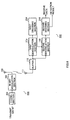
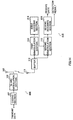
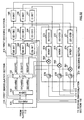
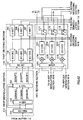
FIG.1 is a block diagram showing the configuration
of a radio communication system according to Embodiment
1 of the present invention;
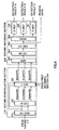
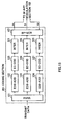
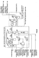
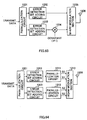
FIG.2 is a block diagram showing the internal
configuration of the coding section of the transmitting
apparatus shown in FIG.1;
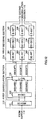
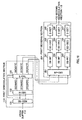
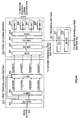
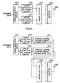
FIG.3 is a block diagram showing the internal
configuration of the first demodulation section and first
decoding section of the receiving apparatus shown in
FIG.1;
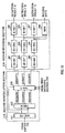
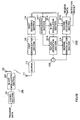
FIG.4 is a block diagram showing the internal
configuration of the second demodulation section and
second decoding section of the receiving apparatus shown
in FIG.1;
FIG.5 is a drawing for explaining an 8PSK signal
space diagram;
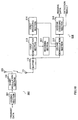
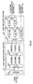
FIG.6 is a block diagram showing the configuration
of a radio communication system according to Embodiment
2 of the present invention;
FIG.7 is a block diagram showing the internal
configuration of the coding section of the transmitting
apparatus shown in FIG.6;
FIG.8 is a block diagram showing the internal
configuration of the first demodulation section and first
decoding section of the receiving apparatus shown in
FIG.6;
FIG.9 is a block diagram showing the internal
configuration of the second demodulation section and
second decoding section of the receiving apparatus shown
in FIG.6;
FIG.10 is a block diagram showing the configuration
of a radio communication system according to Embodiment
3 of the present invention;
FIG.11 is a block diagram showing the internal
configuration of the coding section of the transmitting
apparatus shown in FIG.10;
FIG.12 is a block diagram showing the internal
configuration of the first demodulation section and first
decoding section of the receiving apparatus shown in
FIG.10;
FIG.13 is a block diagram showing the internal
configuration of the second demodulation section and
second decoding section of the receiving apparatus shown
in FIG.10;
FIG.14 is a block diagram showing the configuration
of a radio communication system according to Embodiment
4 of the present invention;
FIG.15 is a block diagram showing the internal
configuration of the coding section of the transmitting
apparatus shown in FIG.14;
FIG.16 is a block diagram showing the internal
configuration of the first demodulation section and first
decoding section of the receiving apparatus shown in
FIG.14;
FIG.17 is a block diagram showing the internal
configuration of the second demodulation section and
second decoding section of the receiving apparatus shown
in FIG.14;
FIG.18 is a block diagram showing the configuration
of a radio communication system according to Embodiment
5 of the present invention;
FIG.19 is a block diagram showing the internal
configuration of the first demodulation section, first
decoding section, and recoding section of the receiving
apparatus shown in FIG.18;
FIG.20 is a block diagram showing the internal
configuration of the second demodulation section and
second decoding section of the receiving apparatus shown
in FIG.18;
FIG.21 is a block diagram showing the internal
configuration of the first demodulation section, first
decoding section, and recoding section of the receiving
apparatus shown in FIG.18;
FIG. 22 is a block diagram showing the configuration
of- a radio communication system according to Embodiment
6 of the present invention;
FIG.23 is a block diagram showing the internal
configuration of the first demodulation section and first
decoding section of the receiving apparatus shown in
FIG.22;
FIG.24 is a block diagram showing the internal
configuration of the second demodulation section of the
receiving apparatus shown in FIG.22;
FIG.25 is a block diagram showing the configuration
of a radio communication system according to Embodiment
7 of the present invention;
FIG.26 is a block diagram showing the internal
configuration of the first demodulation section, first
decoding section, and recoding section of the receiving
apparatus shown in FIG.25;
FIG.27 is a block diagram showing the internal
configuration of the second demodulation section of the
receiving apparatus shown in FIG.25;
FIG.28 is a block diagram showing the internal
configuration of the second demodulation section of a
receiving apparatus of a radio communication system
according to Embodiment 8 of the present invention;
FIG.29 is a block diagram showing the internal
configuration of the second demodulation section of a
receiving apparatus of a radio communication system
according to Embodiment 9 of the present invention;
FIG.30 is a block diagram showing the internal
configuration of the first demodulation section, first
decoding section, and recoding section of a receiving
apparatus of a radio communication system according to
Embodiment 10 of the present invention;
FIG.31 is a block diagram showing the internal
configuration of the second demodulation section of a
receiving apparatus of a radio communication system
according to Embodiment 10 of the present invention;
FIG.32 is a block diagram showing the internal
configuration of the first demodulation section, first
decoding section, and recoding section of a receiving
apparatus of a radio communication system according to
Embodiment 10 of the present invention;
FIG.33 is a block diagram showing the configuration
of the first demodulation section and first decoding
section of a receiving apparatus of a radio communication
system according to Embodiment 11 of the present
invention;
FIG.34 is a block diagram showing the internal
configuration of the second demodulation section and
second decoding section of a receiving apparatus of a
radio communication system according to Embodiment 11
of the present invention;
FIG.35 is a block diagram showing the configuration
of the second demodulation section and second decoding
section of a receiving apparatus of a radio communication
system according to Embodiment 12 of the present
invention;
FIG.36 is a block diagram showing the internal
configuration of the first demodulation section, first
decoding section, and recoding section of a receiving
apparatus of a radio communication system according to
Embodiment 13 of the present invention;
FIG.37 is a block diagram showing the internal
configuration of the second demodulation section and
second decoding section of a receiving apparatus of a
radio communication system according to Embodiment 13
of the present invention;
FIG.38 is a block diagram showing the configuration
of a radio communication system according to Embodiment
14 of the present invention;
FIG.39 is a block diagram showing the internal
configuration of the first demodulation section, first
decoding section, and recoding section of the receiving
apparatus shown in FIG.38;
FIG.40 is a block diagram showing the internal
configuration of the second demodulation section and
second decoding section of the receiving apparatus shown
in FIG.38;
FIG.41 is a block diagram showing the configuration
of the second demodulation section of a receiving
apparatus of a radio communication system according to
Embodiment 15 of the present invention;
FIG.42 is a block diagram showing the configuration
of a radio communication system according to Embodiment
16 of the present invention;
FIG.43 is a block diagram showing the internal
configuration of the coding section of the transmitting
apparatus shown in FIG.42;
FIG.44 is a block diagram showing the internal
configuration of the first demodulation section, first
decoding section, and recoding section of the receiving
apparatus shown in FIG.42;
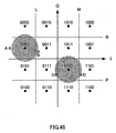
FIG.45 is a drawing for explaining a 16QAM signal
space diagram;
FIG.46 is a block diagram showing the internal
configuration of the second demodulation section of the
receiving apparatus shown in FIG.42;
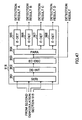
FIG.47 is a block diagram showing the internal
configuration of the second decoding section of the
receiving apparatus shown in FIG.42;
FIG.48 is a block diagram showing the configuration
of the second demodulation section of a receiving
apparatus of a radio communication system according to
Embodiment 17 of the present invention;
FIG.49 is a block diagram showing the configuration
of a radio communication system according to Embodiment
18 of the present invention;
FIG.50 is a block diagram showing the internal
configuration of the first demodulation section, first
decoding section, and recoding section of the receiving
apparatus shown in FIG.49;
FIG.51 is a block diagram showing the internal
configuration of the second demodulation section and
second decoding section of the receiving apparatus shown
in FIG.49;
FIG.52A is a signal arrangement diagram showing
received signals, replicas, and signals after replica
elimination of a receiving apparatus according to
Embodiment 18 of the present invention;
FIG.52B is a signal arrangement diagram showing
received signals, replicas, and signals after replica
elimination of a receiving apparatus according to
Embodiment 18 of the present invention;
FIG.53A is a signal arrangement diagram showing
received signals, replicas, and signals after replica
elimination of a receiving apparatus according to
Embodiment 18 of the present invention;
FIG.53B is a signal arrangement diagram showing
received signals, replicas, and signals after replica
elimination of a receiving apparatus according to
Embodiment 18 of the present invention;
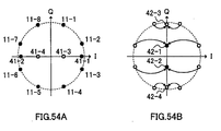
FIG.54A is a signal arrangement diagram showing
received signals, replicas, and signals after replica
elimination of a receiving apparatus according to
Embodiment 18 of the present invention;
FIG.54B is a signal arrangement diagram showing
received signals, replicas, and signals after replica
elimination of a receiving apparatus according to
Embodiment 18 of the present invention;
FIG.55 is a flowchart showing the flow of a reception
method of a receiving apparatus according to Embodiment
18 of the present invention;
FIG.56 is a flowchart showing the flow of a reception
method of a receiving apparatus according to Embodiment:
18 of the present invention;
FIG.57A is a signal arrangement diagram showing
received signals, replicas, and signals after replica
elimination of a receiving apparatus according to
Embodiment 18 of the present invention;
FIG.57B is a signal arrangement diagram showing
received signals, replicas, and signals after replica
elimination of a receiving apparatus according to
Embodiment 18 of the present invention;
FIG.58A is a signal arrangement diagram showing
received signals, replicas, and signals after replica
elimination of a receiving apparatus according to
Embodiment 18 of the present invention;
FIG.58B is a signal arrangement diagram showing
received signals, replicas, and signals after replica
elimination of a receiving apparatus according to
Embodiment 18 of the present invention;
FIG.59A is a signal arrangement diagram showing
received signals, replicas, and signals after replica
elimination of a receiving apparatus according to
Embodiment 18 of the present invention;
FIG.59B is a signal arrangement diagram showing
received signals, replicas, and signals after replica
elimination of a receiving apparatus according to
Embodiment 18 of the present invention;
FIG.60A is a signal arrangement diagram showing
received signals, replicas, and signals after replica
elimination of a receiving apparatus according to
Embodiment 18 of the present invention;
FIG.60B is a signal arrangement diagram showing
received signals, replicas, and signals after replica
elimination of a receiving apparatus according to
Embodiment 18 of the present invention;
FIG.61 is a block diagram showing the configuration
of a radio communication system according to Embodiment
19 of the present invention;
FIG.62 is a block diagram showing the internal
configuration of the first demodulation section, first
decoding section, and recoding section of a receiving
apparatus of a radio communication system according to
Embodiment 20 of the present invention;
FIG.63 is a block diagram showing a configuration
of a transmitting apparatus according to Embodiment 21
of the present invention;
FIG.64 is a block diagram showing a configuration
of a transmitting apparatus according to Embodiment 21
of the present invention;
FIG.65 is a block diagram showing a configuration
of a transmitting apparatus according to Embodiment 21
of the present invention;
FIG.66 is a block diagram showing a configuration
of a transmitting apparatus according to Embodiment 21
of the present invention;
FIG.67 is a block diagram showing a configuration
of a transmitting apparatus according to Embodiment 21
of the present invention;
FIG.68 is a block diagram showing the configuration
of a radio communication system according to Embodiment
22 of the present invention;
FIG.69 is a block diagram showing the internal
configuration of the first demodulation section, first
decoding section, and interleaving section of the
receiving apparatus shown in FIG.68;
FIG.70 is a block diagram showing the internal
configuration of the first demodulation section, first
decoding section, and interleaving section of a receiving
apparatus of a radio communication system according to
Embodiment 23 of the present invention;
FIG.71 is a block diagram showing the internal
configuration of the first demodulation section, first
decoding section, and interleaving section of a receiving
apparatus of a radio communication system according to
Embodiment 24 of the present invention;
FIG.72 is a block diagram showing the internal
configuration of the first demodulation section, first
decoding section, and interleaving section of a receiving
apparatus of a radio communication system according to
Embodiment 25 of the present invention;
FIG.73A is a signal arrangement diagram for
explaining a retransmission method of Embodiment 26 of
the present invention;
FIG.73B is a signal arrangement diagram for
explaining a retransmission method of Embodiment 26 of
the present invention;
FIG.73C is a signal arrangement diagram for
explaining a retransmission method of Embodiment 26 of
the present invention;
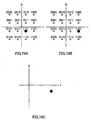
FIG.74A is a signal arrangement diagram for
explaining a retransmission method of Embodiment 26 of
the present invention;
FIG.74B is a signal arrangement diagram for
explaining a retransmission method of Embodiment 26 of
the present invention;
FIG.74C is a signal arrangement diagram for
explaining a retransmission method of Embodiment 26 of
the present invention; and
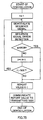
FIG.75 is a flowchart showing the demodulation
procedure of a receiving-side apparatus according to
Embodiment 26 of the present invention.
Best Mode for Carrying out the Invention
The present inventors arrived at the present
invention by noting the per-bit mapping state in an M-ary
modulation signal space diagram, and finding that, if
an error is detected for a specific bit of a signal point,
the likelihood of other bits can be obtained with high
precision by determining bits for which that error was
not detected.
That is to say, the essence of the present invention
is to have a transmitting apparatus perform transmissiom
with data error-correction-coded as a plurality of
independent error detection units arranged in one
transmission unit, and to have a receiving apparatus
perform error detection on decoded data for each
independent error detection unit, and modify the
likelihood of each bit according to the error detection
result.
It may happen that a likelihood once calculated by
a receiving apparatus according to an embodiment is
modified, and a new likelihood is obtained. This
pre-modification likelihood is called "a candidate
likelihood".
With reference now to the accompanying drawings,
embodiments of the present invention will be explained
in detail below.
(Embodiment 1)
FIG.1 is a block diagram showing the configuration
of a radio communication system according to Embodiment
1 of the present invention. In the radio communication
system shown in FIG.1, radio communications are performed
between a transmitting apparatus 100 and receiving
apparatus 110. Unless indicated otherwise, in the
following embodiments a case in which 8PSK is performed
will be described by way of example.
In the transmitting apparatus 100, a coding section
101 performs error detection coding of transmit data for
each predetermined error detection unit, and performs
error correction coding for each predetermined error
correction unit. An M-ary modulation section 102
performs M-ary modulation of the output signal from the
coding section 101, and performs radio transmission of
this signal from an antenna 103.
In the receiving apparatus 110, a signal received
from an antenna 111 is first stored in a buffer 112, and
then output to a first demodulation section 113 and a
second demodulation section 115 for each predetermined
transmission unit. Here, a transmission unit is a unit
on which one modulation processing operation and
demodulation processing operation are performed.
Normally, modulation processing and demodulation
processing are performed on a symbol-by-symbol basis.
In this embodiment, the following description will assume
that modulation processing and demodulation processing
are performed on a symbol-by-symbol basis.
The first demodulation section 113 demodulates the
received signal and outputs the result of demodulation
to a first decoding section 114. The first decoding
section 114 performs error correction decoding of the
received signal, and also performs error detection on
the result of demodulation. The result of this error
detection is output to the second demodulation section
115. The second demodulation section 115 refers to the
result of error detection by the first decoding section
114 and demodulates the received signal again, and outputs
the result of demodulation to a second decoding section
116. The second decoding section 116 performs error
correction decoding on the result of demodulation by the
second demodulation section 115, and obtains receive
data.
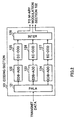
FIG.2 is a block diagram showing the internal
configuration of the coding section 101 of the
transmitting apparatus 100 shown in FIG.1. In FIG.2,
transmit data is first input to a parallelization circuit
(PALA) 121. The parallelization circuit 121
parallelizes the transmit data into 3 sequences, and
outputs the parallelized transmit data to error detection
bit adding circuits (EDB-ADD) 122 through 124.
Error detection bit adding circuits 122 through 124
add error detection bits to input bits parallelized into
3 sequences from the parallelization circuit 121 for each
predetermined error detection unit. By this means, the
transmit data is distributed into 3 independent kinds
of error detection units.
Error correction coding circuits (EC-COD) 125
through 127 perform error correction coding of the coded
bit strings for each predetermined error correction unit,
and output the resulting bit strings to an interleaving
circuit (INTER) 128. The interleaving circuit 128
permutes the error-correction-coded coded bit strings
in accordance with a predetermined rule, and outputs the
resulting bit strings to the M-ary modulation section
102.
Transmit data that has undergone error detection
coding on a sequence-by-sequence basis in this way has
its data order modified, and is then arranged in one symbol
every 3 bits. Therefore, bits belonging to independent
error detection units are mixed in one symbol. In other
words, the M-ary modulation section 102 arranges
error-detection-coded data in one transmission unit
(symbol).
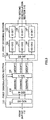
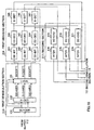
FIG.3 is a block diagram showing the internal
configuration of the first demodulation section 113 and
first decoding section 114 of the receiving apparatus
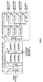
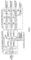
110 shown in FIG.1. FIG.4 is a block diagram showing
the internal configuration of the second demodulation
section 115 and second decoding section 116 of the
receiving apparatus 110 shown in FIG.1.
First, the configuration of the first demodulation
section 113 will be described in detail.
A quadrature demodulation circuit (QU-DEM) 131
separates a received signal for one symbol output from
the buffer 112 into an I signal and Q signal, and outputs
these to a hard decision circuit (H-DEC) 132 and likelihood
calculation circuit (L-CAL) 133. The hard decision
circuit 132 performs hard decision processing on the
received signal and calculates a hard decision value for
each bit. The likelihood calculation circuit 133
calculates a likelihood (soft decision value) for each
bit based on the hard decision value output from the hard
decision circuit 132 and the received signal output from
the quadrature demodulation circuit 131. The likelihood
calculation circuit 133 may determine a likelihood by
calculating the distance from a received signal point
to the nearest identifying axis, for example. A
likelihood obtained by such calculation is output to a
de-interleaving circuit (DE-INT) 141 provided in the
first decoding section 114.
Next, the configuration of the first decoding
section 114 will be described in detail.
The de-interleaving circuit 141 permutes
likelihoods (soft decision values) output from the
likelihood calculation circuit 133 in accordance with
a predetermined rule corresponding to the permutation
rule in the interleaving circuit 128 provided in the
transmitting apparatus 100, and restores the data to its
original order. Error correction decoding circuits
(EC-DEC) 142 through 144 perform error correction
decoding of the individual soft decision values
independently, and output the results of decoding to error
detection circuits (E-DET) 145 through 147. Error
detection circuits 145 through 147 perform error
detection independently, and output the results of
detection to a likelihood calculation section 153
provided in the second demodulation section 115.
Next, the configuration of the second demodulation
section 115 will be described in detail.
A quadrature demodulation circuit (QU-DEM) 151
separates a received signal for one symbol output from
the buffer 112 into an I signal and Q signal, and outputs
these to a hard decision circuit (H-DEC) 152 and likelihood
calculation circuit (L-CAL) 153. The hard decision
circuit 152 performs hard decision processing on the
received signal and calculates a hard decision value for
each bit. The calculated hard decision values are output
to the likelihood calculation circuit 153. The
likelihood calculation circuit 153 first calculates
candidate likelihoods in the same way as likelihood
calculation circuit 133, and modifies the calculated
candidate likelihoods with reference to the error
detection results output from the first decoding section
114. In other words, the likelihood calculation circuit
153 recalculates the likelihood of a bit contained in
an error detection unit in which an error was detected.
Post-modification likelihoods obtained by means of
recalculation are output to a de-interleaving circuit
(DE-INT) 161 provided in the second decoding section 116.
Next, the configuration of the second decoding
section 116 will be described in detail.
De-interleaving circuit 161 permutes likelihoods
(soft decision values) output from likelihood calculation
circuit 153 in accordance with a predetermined rule
corresponding to the permutation rule in the interleaving
circuit 128 provided in the transmitting apparatus 100,
and restores the data to its original order. Error
correction decoding circuits (EC-DEC) 162 through 164
perform error correction decoding of the individual soft
decision values independently, based on likelihoods
recalculated by likelihood calculation circuit 153, and
output the results of decoding to error detection circuits
(E-DET) 165 through 167 and a serialization circuit (SERI)
168. Error detection circuits 165 through 167 perform
error detection for the respective error correction
decoding results. The detection results are used to
detect the presence or absence of an error in the receive
data. The detection results are also transmitted to the
transmitting apparatus and used in Automatic Repeat
Request (ARQ) processing. The serialization circuit 168
serializes the error correction decoding results and
obtains receive data.
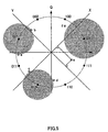
Likelihood calculation in likelihood calculation
circuit 153 will now be described in detail with reference
to FIG.5. FIG. 5 is a drawing for explaining an 8PSK signal
space diagram. As shown in this drawing, in 8PSK, 8 signal
points are arranged at equal intervals (π/8 intervals)
on a circle with the origin of the I-axis and Q-axis as
its center. The 8 signal points are assigned values 000
through 111 as shown in FIG.5. In this embodiment, the
3-bit values assigned to the signal points are designated
"S0", "S1", and "S2" in order from the left side looking
at the drawing. For example, for the signal point
indicating "101", S0=1, S1=0, and S2=1; and for the signal
point indicating "100", S0=1, S1=0, and S2=0. Also, in
this embodiment, the leftmost bit of the bits of each
signal point is referred to as the most significant bit.
That is to say, "S0" is the most significant bit, "S1"
is the second most significant bit, and "S2" is the third
most significant bit. "S2" can also be referred to as
the least significant bit.
Here, by way of example, a case will be described
in which, with regard to likelihood calculation when a
received signal is observed at the point e position, bits
belonging to 3 kinds of error detection units are arranged
in a received symbol, and the most significant 2 bits
(that is, "S0" and "S1") are determined to be error-free
by the first decoding section 114. When an error is not:
detected for the most significant 2 bits, it is confirmed
that the most significant 2 bits are "10" (that is, S0=1
and S1=0), and therefore the received signal is "101"
or "100". It is assumed that, when the received signal
is observed at point e, S1 was erroneous but the error
has been corrected by error correction decoding in the
first decoding section 114, and an error has not been
detected.
With a normal phase modulation method such as 8PSK,
likelihood is determined by calculating the distance from
the received signal point (here, point e) to the nearest
identifying axis (here, the Y-axis), but by referring
to the error detection results for the most significant
2 bits it is seen that the received signal is "101" or
"100", and therefore the identifying axis is changed to
the X-axis, which identifies these values "101" and "100",
and the distance from point e to the X-axis is taken as
the likelihood. By this means, the likelihood can be
calculated more accurately for least significant bit S2.
The operation of a radio communication system that
has the above configuration will now be described.
First, in the transmitting apparatus 100, transmit
data is parallelized by the parallelization circuit 121,
and error detection bits are added by error detection
bit adding circuits 122 through 124 for each predetermined
error detection unit. Then error correction coding is
performed by error correction coding circuits 125 through
127 for each predetermined error correction unit, the
data order is modified by the interleaving circuit 128
in accordance with a predetermined rule, 8PSK modulation
is performed by the M-ary modulation section 102, and
the resulting signal is output to the antenna 103.
In the receiving apparatus, a received signal is
output from the buffer 112 to the first demodulation
section 113 and second demodulation section 115. The
received signal undergoes quadrature modulation by the
first demodulation section 113, after which likelihood
calculation is performed and the signal undergoes
decoding and error detection based on the likelihoods
in the first decoding section 114. That is to say, the
received signal is separated into an I signal and Q signal
by quadrature demodulation circuit 131, and is subjected
to hard decision processing by hard decision circuit 132.
In likelihood calculation circuit 133, received signal
soft decision values (likelihoods) are calculated based
on the hard decision results and the received signal
following quadrature demodulation, and the calculated
likelihoods are output to de-interleaving circuit 141.
The soft decision values are permuted by de-interleaving
circuit 141 in accordance with a predetermined rule, and
undergo error correction decoding by error correction
decoding circuits 142 through 144 and error detection
decoding by error detection circuits 145 through 147.
The results of error detection decoding are output to
likelihood calculation section 153.
Furthermore, the received signal undergoes
quadrature modulation in the second demodulation section
115, after which likelihoods are recalculated, and
decoding and error detection are performed based on the
recalculated likelihoods in the second decoding section
116. That is to say, the received signal is separated
into an I signal and Q signal by quadrature demodulation
circuit 151, and subjected to hard decision processing
by hard decision circuit 152. The I signal and Q signal
separated by quadrature demodulation circuit 151, and
the hard decision values obtained by hard decision circuit
152, are output to likelihood calculation circuit 153.
In likelihood calculation circuit 153, likelihoods are
recalculated based on the input I signal, Q signal, hard
decision values, and error detection results.
Recalculated likelihoods are output together with
non-recalculated likelihoods to de-interleaving circuit
161.
In de-interleaving circuit 161, the data order is
restored to what it was prior to interleaving. In error
correction decoding circuits 162 through 164, error
correction decoding is performed using the recalculated
likelihoods. The demodulation results are
independently subjected to individual error correction
decoding by error detection circuits 165 through 167.
Furthermore, the demodulation results are serialized by
the serialization circuit 168, and this serialized data
is obtained as receive data.
Thus, according to this embodiment, transmission
is performed with data error-correction-coded as a
plurality of independent error detection units arranged
in one transmission unit, and in the receiving apparatus,
error detection is performed on decoded data for each
independent error detection unit, and the likelihood of
each bit is modified according to the error detection
result, as a result of which error correction capability
is improved and the probability of demodulation results
being error-free is increased. Moreover, when a radio
communication system according to this embodiment is
combined with ARQ, error-free communication is achieved
with fewer retransmissions, enabling the number of
retransmissions to be reduced, and thereby improving
transmission efficiency.
Furthermore, in this embodiment, when the error
detection unit and the error correction unit are made
the same, it is not necessary for error correction decoding
to be performed again by the second decoding section 116
for bits contained in a unit for which an error was not
detected in the first decoding section 114, thus enabling
the amount of computation to be reduced. Also, making
the error detection unit and the error correction unit
the same facilitates combination with hybrid ARQ that
combines an error correction code with ARQ.
In this embodiment, 3 kinds of independent error
detection units are provided by distributing transmit
data into 3 sequences that are subjected to error detection
coding individually, but a plurality of independent error
detection units may also be provided. That is to say,
a transmitting apparatus according to the present
invention may arrange bits belonging to an independent
plurality of error detection units in one symbol. For
example, bits belonging to 2 kinds of error detection
units may be arranged in one symbol by means of M-ary
modulation, or bits belonging to 4 kinds of error detection
units may be arranged in one symbol by means of M-ary
modulation. Moreover, the number of error detection
units contained in one symbol may be modified as
appropriate for each modulation unit (that is, on a
symbol-by-symbol basis).
(Embodiment 2)
Embodiment 2 of the present invention is a variant
of Embodiment 1, and describes a case in which a plurality
of error detection units are taken together as one error
correction unit.
FIG.6 is a block diagram showing the configuration
of a radio communication system according to Embodiment
2 of the present invention. In the radio communication
system shown in FIG.6, radio communications are performed
between a transmitting apparatus 200 and receiving
apparatus 210. In the transmitting apparatus. 200, the
configuration of the coding section 201 differs from that
of the coding section 101 shown in FIG.1, and in the
receiving apparatus 210, the first decoding section 214
and second decoding section 216 differ from the first
decoding section 114 and second decoding section 116 shown
in FIG.1.
FIG.7 is a block diagram showing the internal
configuration of the coding section 201 of the
transmitting apparatus 200 shown in FIG.6. Parts in FIG.7
identical to those in FIG.2 are assigned the same codes
as in FIG.2 and their detailed explanations are omitted.
In the coding section 201 shown in FIG.7, transmit data
to which error detection bits have been added by error
detection bit adding circuits 122 through 124 is
serialized by a serialization circuit 221, undergoes
error correction coding by an error correction coding
circuit 222, has its data order modified by a
de-interleaving circuit 223 in accordance with a
predetermined rule, is parallelized into 3 sequences by
a parallelization circuit 224, and is output to an M-ary
modulation section 102.
FIG.8 is a block diagram showing the internal
configuration of the first demodulation section 113 and
first decoding section 214 of the receiving apparatus
210 shown in FIG.6. FIG.9 is a block diagram showing
the internal configuration of the second demodulation
section 115 and second decoding section 216 of the
receiving apparatus 210 shown in FIG.6. Parts in FIG.8
and FIG.9 identical to those in FIG.3 or FIG.4 are assigned
the same codes as in FIG.3 or FIG.4 and their detailed
explanations are omitted.
Soft decision values (likelihoods) obtained on a
bit-by-bit basis by a likelihood calculation circuit 133
in the first demodulation section 113 are serialized by
a serialization circuit 241, and are permuted in a
de-interleaving circuit 242 in accordance with a
predetermined rule corresponding to the permutation rule
in the interleaving circuit 223 provided in the
transmitting apparatus 200. An error correction
decoding circuit 243 performs error correction decoding
using likelihoods output from this de-interleaving
circuit 242. Decoding results are parallelized into 3
sequences by a parallelization circuit 244, and the
parallelized decoding results are output to error
detection circuits 145 through 147 respectively.
In the second demodulation section 115, likelihoods
are recalculated with reference to the error detection
results output from the first decoding section 214, and
the recalculated likelihoods are output to a
serialization circuit 261. The recalculated
likelihoods (soft decision values) are serialized by
serialization circuit 261, and are permuted in a
de-interleaving circuit 262 in accordance with a
predetermined rule corresponding to the permutation rule
in the interleaving circuit 223 provided in the
transmitting apparatus 200. An error correction
decoding circuit 263 performs error correction decoding
using the likelihoods output from this de-interleaving
circuit 262. Decoding results are parallelized into 3
sequences by a parallelization circuit 264, and the
parallelized decoding results are output to error
detection circuits 165 through 167 respectively.
Thus, according to this embodiment, in the error
correction coding circuit 222 bit strings belonging to
a plurality of error detection units are made into one
error correction unit, and error correction coding is
performed on this error correction unit, so that the error
correction unit is larger than when error correction
coding is performed independently for each error
detection unit. As error correction decoding circuits
243 and 263 perform error correction decoding using this
large error correction unit, error correction capability
can be improved. A particularly marked improvement in
error correction capability is evident when a turbo code
is used as the error correction code.
In this embodiment, error correction coding is
performed after 3 kinds of error correction units have
all been gathered together into one error correction unit,
but the present invention is not limited to this, and
it is also possible for error correction coding to be
performed using an error correction unit into which a
plurality of error correction units have been gathered
together.
(Embodiment 3)
Embodiment 3 of the present invention is a variant
of Embodiment 1, and describes a case in which the number
of independent error detection units contained in one
symbol is made identical to the number of bits arranged
in one symbol by providing error detection units that
differ according to the bit position, and performing
interleaving for each error detection unit.
FIG.10 is a block diagram showing the configuration
of a radio communication system according to Embodiment
3 of the present invention. In the radio communication
system shown in FIG.10, radio communications are
performed between a transmitting apparatus 300 and
receiving apparatus 310. In the transmitting apparatus
300, the configuration of the coding section 301 differs
from that of the coding section 101 shown in FIG.1, and
in the receiving apparatus 310, the first decoding section
314 and second decoding section 316 differ from the first
decoding section 114 and second decoding section 116 shown
in FIG.1.
FIG.11 is a block diagram showing the internal
configuration of the coding section 301 of the
transmitting apparatus shown in FIG.10. Parts in FIG.11
identical to those in FIG.2 are assigned the same codes
as in FIG.2 and their detailed explanations are omitted.
In FIG.11, a parallelization circuit 121 parallelizes
transmit data and outputs this parallelized transmit data
to error detection bit adding circuits 122 through 124.
It is here assumed that bit S0 output to error detection
bit adding circuit 122 is positioned as the most
significant bit by an M-ary modulation section 102. It
is also assumed that bit S1 output to error detection
bit adding circuit 123 is positioned as the second most
significant bit by the M-ary modulation section 102, and
that bit S2 output to error detection bit adding circuit
124 is positioned as the third most significant bit by
the M-ary modulation section 102. That is to say, S0,
S1, and S2 belong to different error detection units.
For the sake of explanation, hereinafter in this
Description the error detection unit to which S0 belongs
will be designated error detection unit A, the error
detection unit to which S1 belongs will be designated
error detection unit B, and the error detection unit to
which S3 belongs will be designated error detection unit
C.
Error detection bit adding circuits 122 through 124
perform error detection coding of bits S0 through S2 output
from the parallelization circuit 121 for each
predetermined error detection unit. Specifically,
error detection bit adding circuit 122 adds an error
detection bit to input bit S0 for each predetermined error
detection unit, and obtains a coded bit string P0; error
detection bit adding circuit 123 adds an error detection
bit to input bit S1 for each predetermined error detection
unit, and obtains a coded bit string P1; and error detection
bit adding circuit 124 adds an error detection bit to
input bit S2 for each predetermined error detection unit,
and obtains a coded bit string P2. Coded bit strings P0
through P2 are output to corresponding error correction
coding circuits 125 through 127 respectively.
Error correction coding circuits 125 through 127
perform, for each predetermined error correction unit,
error correction coding of P0 through P2 output from
corresponding error detection bit adding circuits 122
through 124, and output the error-correction-coded data
to corresponding interleaving circuits 321 through 323
respectively. Interleaving circuits 321 through 323
permute the respective input coded bit strings in
accordance with a predetermined rule, and output the
permuted data to the M-ary modulation section 102. The
M-ary modulation section 102 performs 8PSK modulation,
taking the bit output from interleaving circuit 321 as
most significant bit S0, the bit output from interleaving
circuit 322 as second most significant bit S1, and the
bit output from interleaving circuit 323 as third most
significant bit S2.
FIG.12 is a block diagram showing the internal
configuration of the first demodulation section 113 and
first decoding section 314 of the receiving apparatus
310 shown in FIG.10. FIG.13 is a block diagram showing
the internal configuration of the second demodulation
section 115 and second decoding section 316 of the
receiving apparatus 310 shown in FIG.10. Parts in FIG.12
and FIG.13 identical to those in FIG.3 or FIG.4 are assigned
the same codes as in FIG.3 or FIG.4 and their detailed
explanations are omitted.
In the likelihood calculation circuit 133 in the
first demodulation section 113, received signal
likelihoods (soft decision values) are calculated for
S0 through S2. The S0 likelihood (soft decision value)
is output to a de-interleaving circuit 341, the S1
likelihood is output to a de-interleaving circuit 342,
and the S2 likelihood is output to a de-interleaving
circuit 343.
De-interleaving circuit 341 permutes the input bit
string in accordance with the rule corresponding to
interleaving circuit 321, and outputs the permuted bit
string to a corresponding error correction decoding
circuit 142. De-interleaving circuit 342 permutes the
input bit string in accordance with the rule corresponding
to interleaving circuit 322, and outputs the permuted
bit string to a corresponding error correction decoding
circuit 143. De-interleaving circuit 343 permutes the
input bit string in accordance with the rule corresponding
to interleaving circuit 323, and outputs the permuted
bit string to a corresponding error correction decoding
circuit 144. Error correction decoding circuits 142
through 144 perform error correction decoding on the
respective input bit strings.
In the second demodulation section 115, likelihoods
are recalculated with reference to error detection
results output from the first decoding section 314. For
example, if an error is not detected in S0 or S1 by error
detection circuit 145 and error detection circuit 146,
and an error is detected only in S2 by error detection
circuit 147, signal points are limited to 2 points
according to the S0 and S1 hard decision values obtained
by hard decision circuit 152, and likelihoods of S0 through
S2 are recalculated using the identifying axis that
identifies these limited signal points.
Received signal likelihoods (soft decision values)
recalculated in this way are output to corresponding
de-interleaving circuits 361 through 363. That is to say,
the recalculated S0 likelihood is output to
de-interleaving circuit 361, the recalculated S1
likelihood is output to de-interleaving circuit 362, and
the recalculated S2 likelihood is output to
de-interleaving circuit 363.
De-interleaving circuit 361 permutes the input bit
string in accordance with the rule corresponding to
interleaving circuit 321, and outputs the permuted bit
string to a corresponding error correction decoding
circuit 162. De-interleaving circuit 362 permutes the
input bit string in accordance with the rule corresponding
to interleaving circuit 322, and outputs the permuted
bit string to a corresponding error correction decoding
circuit 163. De-interleaving circuit 363 permutes the
input bit string in accordance with the rule corresponding
to interleaving circuit 323, and outputs the permuted
bit string to a corresponding error correction decoding
circuit 164. Error correction decoding circuits 162
through 164 perform error correction decoding on the
respective input bit strings.
Thus, according to this embodiment, when using 8PSK
modulation whereby 3 bits are arranged in one symbol,
transmit data is parallelized into 3 sequences, and an
error detection code is added on a sequence-by-sequence
basis by error detection bit adding circuits 122 through
124. As a result, the number of bits arranged in one symbol
and the number of independent error detection units are
the same. Also, data is permuted on a
sequence-by-sequence basis (that is, for each independent
error detection unit) by interleaving circuits 321
through 323, and 8PSK modulation is performed by the M-ary
modulation section 102, taking the bit output from
interleaving circuit 321 as the most significant bit,
the bit output from interleaving circuit 322 as the second
most significant bit, and the bit output from interleaving
circuit 323 as the third most significant bit. Therefore,
bits contained in 3 kinds of independent error correction
units are arranged in one symbol. That is to say, in each
of the symbols generated sequentially by modulation
processing, the number of independent error detection
units contained in one symbol and the number of bits
arranged in one symbol are the same.
Consequently, when even one of the independent error
detection units is determined to be error-free in error
detection circuits 145 through 147, likelihoods are
recalculated by likelihood calculation circuit 153 with
signal points limited according to bits that are
error-free, enabling likelihoods to be calculated more
accurately.
Also, with 8PSK, the error tolerance of the most
significant 2 bits is better than the error tolerance
of the third most significant bit, and therefore the most
significant 2 bits may be received correctly even if
reception conditions degrade. In such a case, the
probability of an error in the third most significant
bit being corrected is increased by having likelihoods
recalculated by likelihood calculation circuit 153 using
the identifying axis that identifies signal points
limited according to correctly received bits, and having
error correction decoding performed by error correction
decoding circuit 164 using the recalculated, accurate
likelihoods.
Furthermore, in this embodiment, since data is
transmitted that has been subjected to error detection
processing in the transmitting apparatus using error
detection units that differ according to bit positions,
by performing demodulation processing independently in
a receiving apparatus using a different demodulation
pattern for each error detection unit, it is possible
for demodulation to be carried out in the receiving
apparatus without notification of information such as
the modulation method. That is to say, in a radio
communication system according to this embodiment, it
is possible to use the hierarchical demodulation shown
in Japanese Patent Application No.2000-189411, whose
inventors are the present inventors.
(Embodiment 4)
Embodiment 4 of the present invention is a variant
of Embodiment 3, and describes a case in which bit positions
in symbols are modified on a symbol-by-symbol basis.
FIG.14 is a block diagram showing the configuration
of a radio communication system according to Embodiment
4 of the present invention. In the radio communication
system shown in FIG.14, radio communications are
performed between a transmitting apparatus 400 and
receiving apparatus 410. In the transmitting apparatus
400, the configuration of the coding section 401 differs
from that of the coding section 301 shown in FIG.10, and
in the receiving apparatus 410, the first decoding section
414 and second decoding section 416 differ from the first
decoding section 314 and second decoding section 316 shown
in FIG.10.
FIG.15 is a block diagram showing the internal
configuration of the coding section 401 of the
transmitting apparatus shown in FIG.14. Parts in FIG.15
identical to those in FIG.11 are assigned the same codes
as in FIG.11 and their detailed explanations are omitted.
In FIG.15, interleaving circuits 321 through 323 permute
bit strings belonging to error detection units
corresponding to the respective sequences.
Specifically, interleaving circuit 321 permutes a bit
string belonging to error detection unit A, interleaving
circuit 322 permutes a bit string belonging to error
detection unit B, and interleaving circuit 323 permutes
a bit string belonging to error detection unit C. Bits
S0 through S2 belonging to error detection units A through
C are output to a bit position scrambler (BP-SCR) 421.
The bit position scrambler 421 modifies the bit
positions of S0 through S2 in accordance with a
predetermined rule, and outputs S0 through S2 with
modified bit positions to an M-ary modulation section
102. For example, the bit position scrambler 421 may
modify bit position assignments "S0: most significant
bit, S1: second most significant bit, S2: third most
significant bit" in symbol K to "S0: second most
significant bit, S1: third most significant bit, S2: most
significant bit" in following symbol K+1. Such bit
position modifications are made on a symbol-by-symbol
basis.
The M-ary modulation section 102 performs 8PSK
modulation with S0 through S2 output by the bit position
scrambler 421 assigned to their modified positions.
FIG.16 is a block diagram showing the internal
configuration of the first demodulation section 113 and
first decoding section 414 of the receiving apparatus
410 shown in FIG.14. FIG.17 is a block diagram showing
the internal configuration of the second demodulation
section 115 and second decoding section 416 of the
receiving apparatus 410 shown in FIG.14. Parts in FIG.16
and FIG.17 identical to those in FIG.12 or FIG.13 are
assigned the same codes as in FIG.12 or FIG.13 and their
detailed explanations are omitted.
In the likelihood calculation circuit 133 in the
first demodulation section 113, received signal
likelihoods (soft decision values) are calculated for
S0 through S2. The S0, S1, and S2 likelihoods (soft
decision values) are output to a bit position descrambler
(BP-DES) 441.
The bit position descrambler 441 modifies the bit
positions of the likelihoods output from likelihood
calculation circuit 133 in accordance with a
predetermined rule, and outputs likelihoods to
de-interleaving circuits 341 through 343 corresponding
to the modified bit positions. This predetermined rule
corresponds to the rule of the bit position scrambler
421 in the transmitting apparatus. For example, when the
likelihoods of symbol K+1 referred to in the above
description of the bit position scrambler 421 in the
transmitting apparatus are calculated, the bit position
descrambler 441 outputs the S2 likelihood as the
likelihood of the most significant bit, the S0 likelihood
as the likelihood of the second most significant bit,
and the S1 likelihood as the likelihood of the third most
significant bit. The bit position descrambler 441
permutes the likelihoods of the bit positions input in
this way, and outputs S0 to de-interleaving circuit 341,
S1 to de-interleaving circuit 342, and S2 to
de-interleaving circuit 343.
Also, a bit position descrambler 461 modifies the
bit positions of likelihoods recalculated by likelihood
calculation circuit 153 in accordance with a
predetermined rule, and outputs likelihoods to
de-interleaving circuits 361 through 363 corresponding
to the modified bit positions.
Thus, according to this embodiment, the same kind
of effect is obtained as with Embodiment 3, and the
advantageous effect described below is also obtained.
Namely, by modifying the bit positions of bits S0 through
S2 belonging to error correction units A through C in
the bit position scrambler 421, it is possible to scramble
the error tolerances of bits S0 through S2 belonging to
the respective error detection units. That is to say,
S2, which is normally assigned to the least significant
bit, is modulated after being assigned to the most
significant bit or second most significant bit in a
predetermined symbol. Also, S0, which is normally
assigned to the most significant bit, is assigned to the
second most significant bit or least significant bit.
A similar pattern also applies to S1, which is normally
assigned to the second most significant bit. By this
means, the error tolerances of bits belonging to
respective error detection units are made uniform, and
an improvement in overall reception characteristics can
be expected.
(Embodiment 5)
Embodiment 5 of the present invention is a variant
of Embodiment 3, and describes a case in which a signal
that has undergone error correction decoding is recoded
in a receiving apparatus, and candidate likelihoods are
modified using this.
FIG.18 is a block diagram showing the configuration
of a radio communication system according to Embodiment
5 of the present invention. In the radio communication
system shown in FIG.18, radio communications are
performed between a transmitting apparatus 300 and
receiving apparatus 510. The receiving apparatus 510 has
a configuration in which a recoding section 517 has been
added to the receiving apparatus 310 shown in FIG.10.
The recoding section 517 codes again data that has been
decoded by a first decoding section 314.
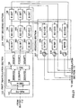
FIG.19 is a block diagram showing the internal
configuration of the first demodulation section 113,
first decoding section 314, and recoding section 517 of
the receiving apparatus 510 shown in FIG.18. FIG.20 is
a block diagram showing the internal configuration of
the second demodulation section 115 and second decoding
section 316 of the receiving apparatus 510 shown in FIG.18.
Parts in FIG.19 and FIG.20 identical to those in FIG.12
or FIG.13 are assigned the same codes as in FIG.12 or
FIG.13 and their detailed explanations are omitted.
In the recoding section 517 of the receiving
apparatus 510 shown in FIG.19, error correction coding
circuits 571 through 573 perform error correction coding
again of demodulation results output from corresponding
error correction decoding circuits 142 through 144, and
output coded bit strings to corresponding interleaving
circuits 574 through 576. Interleaving circuits 574
through 576 permute coded bit strings output from
corresponding error correction coding circuits 571
through 573 in accordance with a predetermined rule. The
permuted coded bit strings are output to a likelihood
calculation circuit 153 provided in the second
demodulation section 115. The predetermined rule used
when permuting the data order here is the same as the
rule used by interleaving circuits 321 through 323
provided in the transmitting apparatus.
In the second demodulation section 115 of the
receiving apparatus 510 shown in FIG.20, a likelihood
calculation circuit 153 uses coded bit strings
re-interleaved by interleaving circuits 574 through 576
to modify candidate likelihoods calculated based on
demodulation results from a quadrature demodulation
circuit 151 and hard decision results from a hard decision
circuit 152. For example, likelihood calculation
circuit 153 may compare demodulation results from
quadrature demodulation circuit 151 with coded bit
strings output from interleaving circuits 574 through
576 on a sequence-by-sequence basis (that is, for each
independent error detection unit) , and make the candidate
likelihood of an error detection unit for which the
demodulation result and coded bit string are determined
to be identical higher than the likelihoods of other error-detection
units.
Thus, according to this embodiment, the second
demodulation section 115 modifies candidate likelihoods
using coded bit strings re-interleaved by interleaving
circuits 574 through 576, and outputs modified
high-precision candidate likelihoods to the second
decoding section 316 as likelihoods. By this means, the
second decoding section 316 performs error correction
decoding using high-precision likelihoods output from
the second demodulation section 115, enabling error
correction capability to be improved.
In this embodiment, it is also possible to add
switches 577 through 579 to the recoding section 517,
as shown in FIG.21, and use interleaving results for
likelihood modification only for error detection units
for which an error is not detected by error detection
circuits 145 through 147.
By this means, likelihoods are modified reflecting
only interleaving results corresponding to error
detection units for which an error is not detected,
enabling more precise likelihoods to be calculated.
(Embodiment 6)
Embodiment 6 of the present invention is a variant
of Embodiment 2. When there are six independent error
detection units in a radio communication system according
to Embodiment 2, for example, it is not possible to arrange
bits belonging to all the error detection units in the
same symbol, andtherefore, even if an error is not detected
for a specific error detection unit, there is a possibility
of not being able to perform likelihood recalculation
that reflects error detection results for bits arranged
in a different symbol from a symbol in which bits belonging
to that error detection unit are arranged.
Thus, in this embodiment, a case is described in
which likelihoods can be obtained more accurately by
multiplying a recalculated likelihood by a compensation
coefficient according to whether or not an error is
detected.
FIG.22 is a block diagram showing the configuration
of a radio communication system according to Embodiment
6 of the present invention. In the radio communication
system shown in FIG.22, radio communications are
performed between a transmitting apparatus 200 and
receiving apparatus 610. In the receiving apparatus 610,
the first decoding section 614 and second demodulation
section 615 differ from the first decoding section 214
and second demodulation section 115 shown in FIG.6.
FIG.23 is a block diagram showing the internal
configuration of the first demodulation section 113 and
first decoding section 614 shown in FIG.22. FIG.24 is
a block diagram showing the internal configuration of
the second demodulation section 615 of the receiving
apparatus 610 shown in FIG.22. Parts in FIG.23 and FIG.24
identical to those in FIG.7 or FIG.8 are assigned the
same codes as in FIG.7 or FIG.8 and their detailed
explanations are omitted.
A de-interleaving circuit 641 in the first decoding
section 614 permutes an output signal from a serialization
circuit 241 in accordance with a predetermined rule
corresponding to the permutation rule in an interleaving
circuit 223 provided in the transmitting apparatus 200,
and outputs a de-interleaving pattern indicating the data
order in the output bit string of that circuit sequentially
to AND circuits 661 through 663 in the second demodulation
section 615. For example, if three independent error
detection units have been set, the de-interleaving
circuit 641 outputs a bit string in the order S0, S1,
S2, S0, S1, S2, and therefore "1" is output to AND circuit
661 at the timing at which S0 is output, "1" is output
to AND circuit 662 at the timing at which S1 is output,
and "1" is output to AND circuit 663 at the timing at
which S2 is output. Also, error detection circuits 145
through 147 output signals indicating error detection
results to a likelihood calculation circuit 153 and AND
circuits 661 through 663. It is here assumed that error
detection circuits 145 through 147 output "1" as an error
detection result when an error is not detected, and "0"
when an error is detected.
AND circuits 661 through 663 calculate the AND of
error detection results output from error detection
circuits 145 through 147 and the de-interleaving pattern
output from the de-interleaving circuit 641, and output
the respective calculation results to corresponding
selection circuits (SELE) 664 through 666. For example,
if an error is not detected in S0 by error detection circuit
145, at the timing at which the de-interleaving circuit
641 outputs S0, "1" is input to AND circuit 661 as the
error detection result, and "1" is input as the
interleaving pattern. In this case, AND circuit 661
outputs "1" to selection circuit 664. If, on the other
hand, an error is detected in S0 by error detection circuit
145, at the timing at which the de-interleaving circuit
641 outputs S0, "0" is input to AND circuit 661 as the
error detection result, and "1" is input as the
interleaving pattern. In this case, AND circuit 661
outputs "0" to selection circuit 664. The same applies
to the output of the other selection circuits, 665 and
666. That is to say, when an error is not detected in
a bit of the corresponding error detection unit in error
detection circuits 145 through 147, AND circuits 661
through 663 output "1" at the processing timing for a
bit of that error detection unit.
"1" and "α" are input to selection circuits 664
through 666. "α" is any real number from 1 up. A
selection circuit. 664 through 666 outputs "α" to a
corresponding multiplier 667 through 669 when "1" is
output from corresponding AND circuit 661 through 663,
and outputs "1" to corresponding multiplier 667 through
669 when "0" is output from corresponding AND circuit
661 through 663.
Multipliers 667 through 669 multiply the output
value (that is, "α" or "1") of the corresponding selection
circuit 664 through 666 by the likelihood output from
likelihood calculation circuit 153. The multiplication
results are output to a serialization circuit 261 provided
in a second decoding section 216.
Thus, in a receiving apparatus according to this
embodiment, when an error is not detected in an error
detection circuit 145 through 147, likelihood
modification is performed by multiplying the likelihood
corresponding to that bit for which an error was not
detected by "α" (≥1). By this means, likelihood
modification is performed so that the likelihood of a
bit for which an error is not detected is made larger
than the likelihood of a bit for which an error is detected,
thus enabling high-precision likelihoods to be obtained.
(Embodiment 7)
Embodiment 7 of the present invention is a variant
of Embodiment 6, differing from Embodiment 6 in that
likelihood modification is performed using a bit string
in which decoding results are recoded and re-interleaved.
FIG.25 is a block diagram showing the configuration
of a radio communication system according to Embodiment
7 of the present invention. In the radio communication
system shown in FIG.25, radio communications are
performed between a transmitting apparatus 200 and
receiving apparatus 710. The receiving apparatus 710 has
a configuration in which a recoding section 717 has been
added between the first decoding section 614 and second
demodulation section 615 in the receiving apparatus 610
shown in FIG.22.
FIG.26 is a block diagram showing the internal
configuration of the first demodulation section 113,
first decoding section 614, and recoding section 717 of
the receiving apparatus 710 shown in FIG.25. FIG.27 is
a block diagram showing the internal configuration of
the second demodulation section 615 of the receiving
apparatus 710 shown in FIG.25. Parts in FIG.26 and FIG.27
identical to those in FIG.23 or FIG.24 are assigned the
same codes as in FIG.23 or FIG.24 and their detailed
explanations are omitted.
An error correction coding circuit 771 performs
error correction coding again of the decoding result
output from an error correction decoding circuit 243,
and outputs the coded bit string to an interleaving circuit
772. The interleaving circuit 772 permutes the coded bit
string output from the error correction coding circuit
771 in accordance with a predetermined rule. The permuted
coded bit string is output to a likelihood calculation
circuit 153 provided in the second demodulation section
615. The predetermined rule used when permuting the data
order in the interleaving circuit 772 is the same as the
rule used by an interleaving circuit 223 provided in the
transmitting apparatus.
The likelihood calculation circuit 153 uses the
coded bit string re-interleaved by the interleaving
circuit 772 to modify likelihoods calculated based on
demodulation results from a quadrature demodulation
circuit 151 and hard decision results from a hard decision
circuit 152 (candidate likelihoods). For example, the
likelihood calculation circuit 153 may compare
demodulation results from the quadrature demodulation
circuit 151 with the coded bit string output from the
interleaving circuit 772 on a sequence-by-sequence basis
(that is, for each independent error detection unit),
and make the candidate likelihood of an error detection
unit for which the demodulation result and coded bit string
are identical higher than the likelihoods of other error
detection units.
Thus', according to this embodiment, candidate
likelihoods are modified using a re-interleaved coded
bit string. By this means, error correction decoding is
performed using high-precision likelihoods, enabling
error correction capability to be improved.
(Embodiment 8)
Embodiment 8 of the present invention describes a
case in which, when, in 8PSK, an error is not detected
in the third most significant bit of the first error
correction decoding result, a more accurate likelihood
is calculated using that error detection result-that is
to say, the likelihood (candidate likelihood) of a
high-order bit is modified in accordance with the decision
value of a low-order bit.
The principle of likelihood modification in this
embodiment will now be explained, referring once again
to FIG.5. Of the signal points shown in FIG.5, two points
present in the same quadrant differ only in the third
most significant bit. For example, to consider the two
signal points "100" and "101" present in the first quadrant,
the most significant 2 bits of both are "10", and they
differ only in the third most significant bit being "1"
or "0". When the "100" point of these two signal points
is determined for a received symbol, at this signal point
the most significant bit, for which the Q-axis is the
decision axis, is nearer a decision axis than the second
most significant bit, for which the I-axis is the decision
axis, and is therefore more likely to be erroneous. On
the other hand, when a received symbol is determined to
be "101", the most significant bit is less likely to be
erroneous than the second most significant bit. Thus,
in 8PSK, there is a correlational relationship between
the error tolerance of the most significant bit and the
error tolerance of the second most significant bit such
that if one is high the other is low, and the error
tolerances of these most significant 2 bits are switched
round in accordance with the value of the third most
significant bit.
Thus, in this embodiment, when an error is not
detected for the third most significant bit, likelihood
modification is performed by multiplying the likelihoods
of the most significant 2 bits by a compensation
coefficient according to the relevant determination
result. Specifically, when the third most significant
bit is "0", the second most significant bit is multiplied
by a larger compensation coefficient, and when the third
most significant bit is "1", the second most significant
bit is multiplied by a larger compensation coefficient.
FIG.28 is a block diagram showing the internal
configuration of the second demodulation section 615 of
a receiving apparatus of a radio communication system
according to Embodiment 8 of the present invention. Parts
in FIG.28 identical to those in FIG.27 are assigned the
same codes as in FIG.27 and their detailed explanations
are omitted.
Except for the internal configuration of the second
demodulation section 615, the configuration of a radio
communication system according to this embodiment is
identical to that of Embodiment 7 shown in FIG.25.
The NOT of an error detection circuit 145 and a
de-interleaving pattern are input to an AND circuit 661.
The NOT of an error detection circuit 146 and a
de-interleaving pattern are input to an AND circuit 662.
The NOT of an error detection circuit 147 and a
de-interleaving pattern are input to an AND circuit 663.
"α" and "β" are input to selection circuits 664 and 665.
The relationship between "α" and "β" is α≥β.
When "1" is output from both AND circuit 661 and
AND circuit 663, and S2 output from an interleaving circuit
772 is "1", selection circuit 664 outputs "β" to a
multiplier 667. When "1" is output from both AND circuit
661 and AND circuit 663, and S2 output from the interleaving
circuit 772 is "0", selection circuit 664 outputs "α"
to multiplier 667.
When "1" is output from both AND circuit 662 and
AND circuit 663, and S2 output from the interleaving
circuit 772 is "1", selection circuit 665 outputs "α"
to a multiplier 668. When "1" is output from both AND
circuit 662 and AND circuit 663, and S2 output from the
interleaving circuit 772 is "0", selection circuit 665
outputs "β" to multiplier 668.
Multiplier 667 and multiplier 668 perform
likelihood modification by multiplying S0 and S1 output
from the likelihood calculation circuit 153 by
compensation coefficients output from corresponding
selection circuits 664 and 665.
Thus, according to this embodiment, high-precision
likelihoods can be obtained by modifying the likelihoods
of the most significant 2 bits with reference to the third
most significant bit.
(Embodiment 9)
Embodiment 9 of the present invention is a variant:
of Embodiment 8, in which the value of the coefficient
by which the most significant bit and second most
significant bit are multiplied is modified.
The principle of compensation coefficient
calculation in this embodiment will now be explained,
referring once again to FIG.5. Referring to FIG.5, the
ratio of the distance to the I-axis to the distance to
the Q-axis from an arbitrary signal point is Sin(π/8)
to Cos(π/8), or Cos(π/8) to Sin(π/8). Therefore, when
an error is not detected in the third most significant
bit in the first error correction decoding result, more
accurate likelihoods can be obtained by performing
multiplication by the coefficient of the most significant
2 bits with Sin(π/8) or Cos(π/8) as a compensation
coefficient according to whether that third most
significant bit is "0" or "1". Specifically, when the
third most significant bit is "0", the ratio of the distance
to the I-axis to the distance to the Q-axis from a signal
point is Cos(π/8) to Sin(π/8). In this case, therefore,
the likelihood of the most significant bit is multiplied
by Sin(n/8), and the second most significant bit is
multipliedby Cos(π/8) . On the other hand, when the third
most significant bit is "1", the ratio of the distance
to the I-axis to the distance to the Q-axis from a signal
point is Sin(π/8) to Cos(π/8). In this case, therefore,
the likelihood of the most significant bit is multiplied
by Cos(π/8), and the second most significant bit is
multiplied by Sin(π/8).
FIG.29 is a block diagram showing the internal
configuration of the second demodulation section 615 of
a receiving apparatus of a radio communication system
according to Embodiment 9 of the present invention. Parts
in FIG.29 identical to those in FIG.28 are assigned the
same codes as in FIG.28 and their detailed explanations
are omitted. Except for the internal configuration of
the second demodulation section 615, the configuration
of a radio communication system according to this
embodiment is identical to that of Embodiment 7 shown
in FIG.25.
"Sin(π/8)", "Cos(π/8)", and "α" are input to
selection circuits 664 and 665.
When "1" is output from both AND circuit 661 and
AND circuit 663, and S2 output from an interleaving circuit
772 is "1", selection circuit 664 outputs "Cos(π/8)" to
a multiplier 667. When "1" is output from both AND circuit
661 and AND circuit 663, and S2 output from the interleaving
circuit 772 is "0", selection circuit 664 outputs
"Sin(π/8)" to multiplier 667. When "1" is output from
AND circuit 661 and "0" is output from AND circuit 663,
α is selected.
When "1" is output from both AND circuit 661 and
AND circuit 663, and S2 output from the interleaving
circuit 772 is "1", selection circuit 665 outputs
"Sin(π/8)" to a multiplier 668. When "1" is output from
both AND circuit 662 and AND circuit 663, and S2 output
from the interleaving circuit 772 is "0", selection
circuit 665 outputs "Cos(π/8)" to multiplier 668. When
"1" is output from AND circuit 662 and "0" is output from
AND circuit 663, α is selected.
Multipliers 667 and 668 perform likelihood
modification by multiplying S0 and S1 output from the
likelihood calculation circuit 153 by compensation
coefficients output from corresponding selection
circuits 664 and 665. A multiplier 669 performs
likelihood modification by multiplying S2 output from
the likelihood calculation circuit 153 by compensation
coefficient α.
Thus, according to this embodiment, high-precision
likelihoods can be obtained by modifying the likelihoods
of the most significant 2 bits with reference to the third
most significant bit.
(Embodiment 10)
Embodiment 10 of the present invention is a variant
of Embodiment 5.
The principle of compensation coefficient
calculation in this embodiment will now be explained,
referring once again to FIG.5. Referring to FIG.5, there
is an 8PSK characteristic whereby, when the most
significant bit is determined to be erroneous, the second
most significant bit and third most significant bit are
unlikely to be erroneous. That is to say, when the most
significant bit is determined to be erroneous, the
corresponding received signal point is located near the
Q-axis, as with point d, for example. When a signal that
should actually be determined to be "010" is received
at point d, the most significant bit is determined to
be erroneous. However, when a received signal point is
near the Q-axis, that received signal point is very far
from the I-axis, and therefore an error is unlikely to
occur in the second most significant bit. Also, when a
received signal point is near the Q-axis, that received
signal point is also very far from the X-axis and Y-axis,
and therefore an error is also unlikely to occur in the
third most significant bit.
Thus, in 8PSK, there is an error tolerance
correlational relationship between bits in the same
symbol such that, when the most significant bit is
susceptible to error (that is, when the error tolerance
of the most significant bit is low) , an error is unlikely
to occur in the second most significant bit or third most
significant bit (that is, the error tolerance of these
bits is high) .
Except for the internal configuration of the
recoding section 517 and second demodulation section 115,
the configuration of a radio communication'system
according to this embodiment is identical to that of
Embodiment 5 shown in FIG.18. FIG.30 is a block diagram
showing the internal configuration of the first
demodulation section 113, first decoding section 314,
and recoding section 517 of a receiving apparatus of a
radio communication system according to Embodiment 10
of the present invention. Parts in FIG.30 identical to
those in FIG.19 are assigned the same codes as in FIG.19
and their detailed explanations are omitted.
In this embodiment, when a bit belonging to an error
detection unit determined to be error-free by the first
decoding section 314 is different before and after error
correction, the likelihoods of other bits contained in
the same symbol as that bit are increased by multiplying
those other bits by one or more compensation coefficients.
The reason for this is that it is probable that, when
a bit belonging to an error detection unit determined
to be error-free by the first decoding section 314 is
different before and after error correction, that bit
has been erroneously determined by a first demodulation
section 113, and that erroneously determined bit has
undergone error correction.
Multipliers 581 through 583 multiply together
pre-error-correction bits output from a likelihood
calculation circuit 133 in a first demodulation section
113, and post-error-correction bits output from
corresponding interleaving circuits 574 through 576.
These multipliers are arranged so as to output "0" when
the result of the operation is negative, and to output
"1" when the result of the operation is positive. As bits
subjected to error correction by error correction
decoding circuits 142 through 144 have different values
before and after error correction, multipliers 581
through 583 output "0" for these bits since the
multiplication results are negative. On the other hand,
bits not subjected to error correction by error correction
decoding circuits 142 through 144 have identical values
before and after error correction, and therefore
multipliers 581 through 583 output "1" for these bits
since the multiplication results are positive. That is
to say, the output values of multipliers 581 through 583
indicate whether or not error correction has been
performed by error correction decoding circuits 142
through 144.
FIG.31 is a block diagram showing the internal
configuration of the second demodulation section 115 of
a receiving apparatus of a radio communication system
according to Embodiment 10 of the present invention. In
this second demodulation section 115 shown in FIG.31,
AND circuits 681 through 683 calculate the AND of
multiplication results output from multipliers 581
through 583 and the de-interleaving pattern output from
corresponding de-interleaving circuits 341 through 343,
and output the respective calculation results to
corresponding selection circuits 684 through 686. For
example, if error correction is not performed by error
detection circuit 142, at the timing at which
de-interleaving circuit 341 outputs S0, "1" is input to
AND circuit 681 as the multiplier output, and "1" is input
as the interleaving pattern. In this case, AND circuit
681 outputs "1" to selection circuit 684. If, on the other
hand, error correction is performed by error detection
circuit 142, at the timing at which de-interleaving
circuit 341 outputs S0, "0" is input to AND circuit 681
as the multiplier output, and "1" is input as the
interleaving pattern. In this case, AND circuit 681
outputs "0" to selection circuit 684. A similar pattern
also applies to the output of AND circuits 682 and 683.
That is to say, when error correction is not performed
by an error detection circuit 145 through 147, the
corresponding AND circuit 681 through 683 outputs "1"
at the processing timing for that bit on which error
correction was not performed.
"α" and "1" are input to selection circuits 684
through 686, where α≥1. When "1" is output from AND
circuit 681, and "0" is output from error detection circuit
145, selection circuit 684 outputs "α" to a multiplier
687 and multiplier 688. On the other hand, when "1" is
output from AND circuit 681, and "1" is output from error
detection circuit 145, selection circuit 684 outputs "1"
to multiplier 687 and multiplier 688. That is to say,
"α" is output from selection circuit 684 when error
correction is performed for S0.
When "1" is output from AND circuit 682, and "0"
is output from error detection circuit 146, selection
circuit 685 outputs "α" to multiplier 687 and a multiplier
689. On the other hand, when "1" is output from AND circuit
682, and "1" is output from error detection circuit 146,
selection circuit 685 outputs "1" to multiplier 687 and
multiplier 689. That is to say, "α" is output from
selection circuit 685 when error correction is performed
for S1.
When "1" is output from AND circuit 683, and "0"
is output from error detection circuit 147, selection
circuit 686 outputs "α" to multiplier 688 and multiplier
689. On the other hand, when "1" is output from AND circuit
683, and "1" is output from error detection circuit 147,
selection circuit 686 outputs "1" to multiplier 688 and
multiplier 689. That is to say, "α" is output from
selection circuit 686 when error correction is performed
for S2.
Multiplier 687 multiplies together the output of
selection circuit 684 and the output of selection circuit
685, and outputs the result of the multiplication to a
multiplier 690. Multiplier 688 multiplies together the
output of selection circuit 684 and the output of selection
circuit 686, and outputs the result of the multiplication
to a multiplier 691. Multiplier 689 multiplies together
the output of selection circuit 685 and the output of
selection circuit 686, and outputs the result of the
multiplication to a multiplier 692.
Multiplier 690 performs likelihood modification by
multiplying the output of multiplier 687 by S2 output
from a likelihood calculation circuit 153. Multiplier
691 performs likelihood modification by multiplying the
output of multiplier 687 by S1 output from the likelihood
calculation circuit 153. Multiplier 692 performs
likelihood modification by multiplying the output of
multiplier 687 by S0 output from the likelihood
calculation circuit 153.
For example, when error correction is performed for
S0, and error correction is not performed for S1 or S2,
selection circuit 684 outputs "α", and selection circuit
685 and selection circuit 686 output "1". Therefore,
multiplier 687 multiplies S2 by "1", multiplier 688
multiplies S1 by "α", and multiplier 689 multiplies S0
by "α".
Thus, according to this embodiment, high-precision
likelihoods can be obtained by modifying the likelihood
of each bit with reference to whether or not error
correction is performed for each bit.
In this embodiment, it is also possible to add .
switches 577 through 579 to the recoding section 517,
as shown in FIG.32, and use interleaving results for
likelihood modification only for error detection units
for which an error is not detected by error detection
circuits 145 through 147.
By this means, according to this embodiment,
likelihoods are modified reflecting only interleaving
results corresponding to error detection units for which
an error is not detected, enabling more precise
likelihoods to be calculated.
(Embodiment 11)
Embodiment 11 of the present invention is a variant
of Embodiment 1, differing from Embodiment 1 in that
likelihoods recalculated by likelihood calculation
circuit 153 are modified in accordance with the error
tolerance of each bit.
As already indicated in Embodiment 8, in 8PSK there
is a correlational relationship between the error
tolerance of the most significant bit and the error
tolerance of the second most significant bit such that
if one is high the other is low. That is to say, in 8PSK,
if the error tolerance of the most significant bit is
high, the error tolerance of the second most significant
bit is low, and conversely, if the error tolerance of
the most significant bit is low, the error tolerance of
the second most significant bit is high.
Thus, in this embodiment, the difference in
likelihood between the most significant 2 bits is
increased by considering the likelihood of the most
significant bit and the likelihood of the second most
significant bit among the likelihoods calculated by
likelihood calculation circuit 153, and dividing the
likelihood of each of these most significant 2 bits by
the absolute value of the likelihood of the other. That
is to say, the likelihood of the most significant bit
is divided by the likelihood of the second most significant
bit, and the likelihood of the second most significant
bit is divided by the likelihood of the most significant
bit. By this means, error correction precision is
improved.
Except for the internal configuration of the first
decoding section 114, second demodulation section 115,
and second decoding section 116, the configuration of
a radio communication system according to this embodiment
is identical to that of Embodiment 1 shown in FIG.1.
FIG.33 is a block diagram showing the configuration of
the first demodulation section 113 and first decoding
section 114 of a receiving apparatus of a radio
communication system according to Embodiment 11 of the
present invention. FIG.34 is a block diagram showing the
internal configuration of the second demodulation section
115 and second decoding section 116 of a receiving
apparatus of a radio communication system according to
Embodiment 11 of the present invention. Parts in FIG.33
and FIG.34 identical to those in FIG.3 or FIG.4 are assigned
the same codes as in FIG.3 or FIG.4 and their detailed
explanations are omitted. The transmitting apparatus of
a radio communication system according to this embodiment
is identical to the transmitting apparatus shown in FIG.2,
and therefore a description of the transmitting apparatus
is omitted here.
In the receiving apparatus shown in FIG.33, an error
detection circuit 145 performs error detection on a most
significant bit that has undergone error correction
decoding, and outputs the error detection result to a
switching circuit 158. An error detection circuit 146
performs error detection on a second most significant
bit that has undergone error correction decoding, and
outputs the error detection result to a switching circuit
159. An error correction decoding circuit 144 performs
error correction decoding on a third most significant
bit, and outputs the result of decoding to an error
detection circuit 167 and serialization circuit 168.
An absolute value calculation circuit ( 154
calculates the absolute value of the likelihood of the
second most significant bit output from likelihood
calculation circuit 153, and outputs this value to a
division circuit 156. An absolute value calculation
circuit 155 calculates the absolute value of the
likelihood of the most significant bit output from
likelihood calculation circuit 153, and outputs this
value to a division circuit 157.
Division circuit 156 divides the likelihood of the
most significant bit output from likelihood calculation
circuit 153 by the absolute value of the likelihood of
the second most significant bit output from absolute value
calculation circuit 154,and outputs the result of the
division to switching circuit 158. Division circuit 157
divides the likelihood of the second most significant
bit output from likelihood calculation circuit 153 by
the absolute value of the likelihood of the most
significant bit output from absolute value calculation
circuit 155,and outputs the result of the division to
switching circuit 159.
Switching circuit 158 outputs to a de-interleaving
circuit 161 either the division result output from
division circuit 156 or the likelihood of the most
significant bit output from likelihood calculation
circuit 153, according to the error detection result for
the most significant bit output from error detection
circuit 145. That is to say, switching circuit 158
outputs the result of division by division circuit 156
to the de-interleaving circuit 161 when the error
detection result indicates that there is an error.
Switching circuit 159 outputs to the de-interleaving
circuit 161 either the division result output from
division circuit 157 or the likelihood of the second most
significant bit output from likelihood calculation
circuit 153, according to the error detection result for
the second most significant bit output from error
detection circuit 146. That is to say, switching circuit
159 outputs the result of division by division circuit
157 to the de-interleaving circuit 161 when the error
detection result indicates that there is an error.
Thus, according to this embodiment, the difference
in likelihood between the most significant 2 bits can
be increased by dividing the likelihood of each of the
most significant 2 bits by the absolute value of the
likelihood of the other. Performing error correction
using likelihoods calculated in this way enables error
correction capability to be improved.
(Embodiment 12)
Embodiment 12 of the present invention is a variant
of Embodiment 11, differing from Embodiment 11 in that
the likelihood modification indicated in Embodiment 11
is performed only for a bit belonging to an error detection
unit for which an error is not detected in the first
decoding section 114.
Except for the internal configuration of the second
demodulation section 115, the configuration of a radio
communication system according to this embodiment is
identical to that of Embodiment 11. FIG.35 is a block
diagram showing the configuration of the second
demodulation section 115 and second decoding section 116
of a receiving apparatus of a radio communication system
according to Embodiment 12 of the present invention.
Parts in FIG.35 identical to those in FIG.34 are assigned
the same codes as in FIG. 34 and their detailed explanations
are omitted.
In the receiving apparatus shown in FIG.35, a logical
NOT circuit 351 calculates the logical NOT of an error
detection result represented by "1" or "0" output from
an error detection circuit 146, and outputs the result
of the calculation to an AND circuit 353. A logical NOT
circuit 352 calculates the logical NOT of an error
detection result represented by "1" or "0" output from
an error detection circuit 145, and outputs the result:
of the calculation to an AND circuit 354.
AND circuit 353 calculates the AND of the error
detection result output from error detection circuit 145
and the output value of logical NOT circuit 351, and outputs
the result of the calculation to a switching circuit 158.
AND circuit 354 calculates the AND of the error detection
result output from error detection circuit 146 and the
output value of logical NOT circuit 352, and outputs the
result of the calculation to a switching circuit 159.
When an error is not detected in the second most
significant bit and an error is detected in the most
significant bit, switching circuit 158 outputs the result
of division by a division circuit 156 to a de-interleaving
circuit 161. In other cases, switching circuit 158
outputs the likelihood calculated by likelihood
calculation circuit 153 to the de-interleaving circuit
161. When an error is not detected in the most significant
bit and an error is detected in the second most significant
bit, switching circuit 159 outputs the result of division
by a division circuit 157 to the de-interleaving circuit
161. In other cases, switching circuit 159 outputs the
likelihood calculated by likelihood calculation circuit
153 to the de-interleaving circuit 161.
Thus, according to this embodiment, likelihood
modification is performed only for a bit, of the most
significant bit and second most significant bit, for which
an error is not detected, thereby enabling likelihoods
to be calculated with greater precision.
(Embodiment 13)
Embodiment 13 of the present invention is a
combination of Embodiment 10 and Embodiment 12, in which
the likelihood modification indicated in Embodiment 12
is performed only for a bit belonging to an error detection
unit for which error correction is not performed in the
first decoding section 314.
Except for the internal configuration of the
recoding section 517 and second demodulation section 115,
the configuration of a radio communication system
according to this embodiment is identical to that of
Embodiment 5 shown in FIG.18. FIG.36 is a block diagram
showing the internal configuration of the first
demodulation section 113, first decoding section 314,
and recoding section 517 of a receiving apparatus of a
radio communication system according to Embodiment 13
of the present invention. FIG.37 is a block diagram
showing the internal configuration of the second
demodulation section 115 and second decoding section 316
of a receiving apparatus of a radio communication system
according to Embodiment 13 of the present invention.
Parts in FIG.36 and FIG.37 identical to those in FIG.20,
FIG. 30, or FIG.35 are assigned the same codes as in FIG.20,
FIG.30, or FIG.35, and their detailed explanations are
omitted.
An error correction decoding circuit 142 performs
error correction decoding of a most significant bit, and
outputs the result of decoding to an error detection
circuit 145 and error correction coding circuit 571. An
error correction decoding circuit 143 performs error
correction decoding of a second most significant bit,
and outputs the result of decoding to an error detection
circuit 146 and error correction coding circuit 572. An
error correction decoding circuit 144 performs error
correction decoding of a third most significant bit, and
outputs the result of decoding to an error detection
circuit 167 and serialization circuit 168.
Error correction coding circuit 571 performs error
correction coding again of the decoding result output
from error correction decoding circuit 142, and outputs
the coded bit string to an interleaving circuit 574.
Error correction coding circuit 572 performs error
correction coding again of the decoding result output
from error correction decoding circuit 143, and outputs
the coded bit string to an interleaving circuit 575.
Interleaving circuit 574 permutes the coded bit string
that has undergone error correction coding in error
correction coding circuit 571 in accordance with a
predetermined rule. Interleaving circuit 575 permutes
the coded bit string that has undergone error correction
coding in error correction coding circuit 572 in
accordance with a predetermined rule.
Multipliers 581 and 582 multiply together a
pre-error-correction bit output from a likelihood
calculation circuit 133 in a first demodulation section
113, and a post-error-correction bit output from
corresponding interleaving circuit 574 or 575. These
multipliers are arranged so as to output "0" when the
result of the operation is negative, and to output "1"
when the result of the operation is positive. As bits
subjected to error correction by error correction
decoding circuits 142 and 143 have different values before
and after error correction, multipliers 581 and 582 output
"0" for these bits since the multiplication results are
negative. On the other hand, bits not subjected to error
correction by error correction decoding circuits 142 and
143 have identical values before and after error
correction, and therefore multipliers 581 and 582 output
"1" for these bits since the multiplication results are
positive. That is to say, the output values of
multipliers 581 and 582 indicate whether or not error
correction has been performed by error correction
decoding circuits 142 and 143.
AND circuit 353 calculates the AND of the error
detection result output from error detection circuit 145,
the output value of logical NOT circuit 351, and the
comparison result signal output from multiplier 581, and
outputs the result of the calculation to a switching
circuit 158. AND circuit 354 calculates the AND of the
error detection result output from error detection
circuit 146, the output value of logical NOT circuit 352,
and the comparison result signal output from multiplier
582, and outputs the result of the calculation to a
switching circuit 159.
When an error is not detected in the second most
significant bit, and an error is detected in the most
significant bit, and there is no change in the signal
code before and after error correction coding for the
most significant bit, switching circuit 158 outputs the
result of division by a division circuit 156 to a
de-interleaving circuit 361. In other cases, switching
circuit 158 outputs the likelihood calculated by
likelihood calculation circuit 153 to de-interleaving
circuit 361. When an error is not detected in the most
significant bit, and an error is detected in the second
most significant bit, and there is no change in the signal
code before and after error correction coding for the
second most significant bit, switching circuit 159
outputs the result of division by a division circuit 157
to a de-interleaving circuit 362. In other cases,
switching circuit 159 outputs the likelihood calculated
by likelihood calculation circuit 153 to de-interleaving
circuit 362.
Thus, according to this embodiment, likelihood
modification is performed only for a bit, of the most
significant bit and second most significant bit, for which
an error has not been detected in the first decoding section
314 and error correction has not been performed, thereby
enabling likelihoods to be calculated with greater
precision.
(Embodiment 14)
FIG. 38 is a block diagram showing the configuration
of a radio communication system according to Embodiment
14 of the present invention. In the radio communication
system shown in FIG.38, radio communications are
performed between a transmitting apparatus 300 and
receiving apparatus 810.
FIG.39 is a block diagram showing the internal
configuration of the first demodulation section 113,
first decoding section 814, and recoding section 517 of
the receiving apparatus 810 shown in FIG.38. FIG.40 is
a block diagram showing the internal configuration of
the second demodulation section 815 and second decoding
section 816 of the receiving apparatus 810 shown in FIG.38.
Parts in FIG.39 and FIG.40 identical to those in FIG.19
or FIG.20 are assigned the same codes as in FIG.19 or
FIG.20 and their detailed explanations are omitted.
An error correction decoding circuit 142 performs
error correction decoding of individual soft decision
values independently, and an error detection circuit 145
outputs the result of decoding to an error detection
circuit 145, error correction coding circuit 571, and
serialization circuit 863.
Error correction coding circuits 571 through 573
perform error correction coding again of demodulation
results output from corresponding error correction
decoding circuits 142 through 144, and output coded bit
strings to corresponding interleaving circuits 574
through 576. Interleaving circuits 574 through 576
permute coded bit strings output from corresponding error
correction coding circuits 571 through 573 in accordance
with a predetermined rule. The predetermined rule used
when permuting the data order here is the same as the
rule used by interleaving circuits 321 through 323
provided in the transmitting apparatus.
Coded bit strings permuted by interleaving circuits
574 and 575 are output to an OR circuit 851 provided in
the second demodulation section 815, and the coded bit
string permuted by interleaving circuit 576 is output
to a likelihood calculation circuit 153 provided in the
second demodulation section 815.
Error detection circuits 145 and 146 output error
detection results to the OR circuit 851, and error
detection circuit 147 outputs the error detection result
to likelihood calculation circuit 153.
The OR circuit 851 calculates the OR of the error
detection result for the error detection unit to which
the most significant bit output from error detection
circuit 145 belongs, and the error detection result for
the error detection unit to which the second most
significant bit output from error detection circuit 146
belongs, and outputs the result of the calculation to
a switching circuit 852 and switching circuit 853.
It is here assumed that error detection circuits
145 through 147 output "1" when an error is not detected,
and output "0" when an error is detected. The OR circuit
851 outputs "1" when an error is not detected in one or
other of the most significant 2 bits.
When "1" is output from the OR circuit 851, switching
circuit 852 outputs S0 from interleaving circuit 574 to
a quadrant determination circuit (QU-DET) 854. When "1"
is output from the OR circuit 851, switching circuit 853
outputs S1 from interleaving circuit 575 to the quadrant
determination circuit 854.
The quadrant determination circuit 854 determines
the quadrant of the I-Q plane to which the received signals
point belongs, based on the most significant 2 bits (that
is, S0 and S1) output from switching circuits 852 and
853. That is to say, the received signal point is
determined to be in the first quadrant when the most
significant 2 bits are "10", to be in the second quadrant
when the most significant 2 bits are "00", to be in the
third quadrant when the most significant 2 bits are "01",
and to be in the fourth quadrant when the most significant
2 bits are "11".
Likelihood calculation circuit 153 modifies the
likelihood of third most significant bit S2 based on the
result of determination by the quadrant determination
circuit 854. Likelihood modification in this embodiment
will now be described with reference to FIG.5. When point
e is determined for a received signal in the first
demodulation section 113, the likelihood of 52 of the
signal received at point e is indicated by the distance
from the identifying axis nearest point e (here, the
Y-axis).
Assuming here that the most significant 2 bits are
decoded as "10" by the second demodulation section 815,
and that neither of these bits is erroneous, the received
signal point is determined by the quadrant determination
circuit 854 to be in the first quadrant. By referring
to the result of determination by the quadrant
determination circuit 854, likelihood calculation
circuit 153 recognizes that the received signal is "101"
or "100", and therefore modifies the identifying axis
to the X-axis, which identifies "101" and "100", and makes
the distance from point e to the X-axis the likelihood.
That is to say, likelihood calculation circuit 153
performs likelihood modification by changing the decision
axis for least significant bit S2.
A de-interleaving circuit 363 permutes an input bit
string in accordance with the rule corresponding to
interleaving circuit 323, and outputs the permuted bit
string to corresponding error correction decoding circuit
164. Error correction decoding circuit 164 performs
error correction coding based on the respective input
bit strings. The serialization circuit 863 serializes
error correction decoding results from error correction
decoding circuits 142 and 143 and error correction
decoding circuit 164, and obtains receive data.
Thus, according to this embodiment, the likelihood
of least significant bit S2 can be modified to a more
precise likelihood based on the error detection results
for the most significant 2 bits.
(Embodiment 15)
Embodiment 15 of the present invention is a variant
of Embodiment 14, differing from Embodiment 14 in that,
in the likelihood modification in Embodiment 14,
likelihood modification is performed with the likelihood
of a bit belonging to an error correction unit for which
an error is not detected in the first decoding section
814 reflected to a greater degree than the likelihood
of an error correction unit for which an error is detected.
Except for the internal configuration of the second
demodulation section 815, the configuration of a radio
communication system according to this embodiment is
identical to that of Embodiment 14 shown in FIG.18.
FIG.41 is a block diagram showing the configuration of
the second demodulation section 815 of a receiving
apparatus of a radio communication system according to
Embodiment 15 of the present invention. Parts in FIG.41
identical to those in FIG.40 are assigned the same codes
as in FIG.40 and their detailed explanations are omitted.
In the receiving apparatus shown in FIG.41, a
switching circuit 855 outputs "α" when an error is not
detected in S0 in an error detection circuit 145, and
outputs "1" when an error is detected. A switching
circuit 856 outputs "α" when an error is not detected
in S1 in an error detection circuit 146, and outputs "1"
when an error is detected. Here, α≥1.
Multipliers 857 and 858 multiply the output values
of corresponding switching circuits 855 and 856 by the
output value of a quadrature demodulation circuit 151.
The multiplication results are output to a likelihood
calculation circuit 153. Likelihood calculation
circuit 153 performs likelihood calculation based on the
multiplication results output from multipliers 857 and
858, and a hard decision value output from a hard decision
circuit 152.
Thus, according to this embodiment, a bit for which
an error is not detected is reflected to a high degree
in likelihood calculation by likelihood calculation
circuit 153, thereby enabling likelihoods to be
calculated with greater precision.
(Embodiment 16)
In Embodiment 16 of the present invention,
likelihood recalculation is described when using 16QAM
as the modulation method. In the radio communication
system shown in FIG.42, radio communications are
performed between a transmitting apparatus 900 and
receiving apparatus 910.
In the transmitting apparatus 900, a coding section
901 performs error detection coding of transmit data for
each predetermined error detection unit, and performs
error correction coding for each predetermined error
correction unit. An M-ary modulation section 902
performs 16QAM modulation of the output signal from the
coding section 901, and performs radio transmission of
this signal from an antenna 903.
In the receiving apparatus 910, a signal received
from an antenna 911 is first stored in a buffer 912, and
then output to a first demodulation section 913 and a
second demodulation section 915 for each predetermined
transmission unit.
The first demodulation section 913 demodulates the
received signal and outputs the result of demodulation
to a first decoding section 914. The first decoding
section 914 performs error correction decoding of the
received signal, and also performs error detection on
the result of demodulation. Data that has undergone error
correction decoding is output to a recoding section 917.
The error detection result is output to the second
demodulation section 915.
The second demodulation section 915 refers to the
data recoded by the recoding section 917 and the result
of error detection by the first decoding section 914 and
demodulates the received signal again, and outputs the
result of demodulation to a second decoding section 916.
The second decoding section 916 performs error correction
decoding on the result of demodulation by the second
demodulation section 915, and obtains receive data.
FIG.43 is a block diagram showing the internal
configuration of the coding section 901 of the
transmitting apparatus 900 shown in FIG.42. In FIG.43,
transmit data is first input to a parallelization circuit
921. The parallelization circuit 921 parallelizes the
transmit data into 4 sequences, and outputs the
parallelized transmit data to error detection bit adding
circuits 922 through 925. The error detection bit adding
circuits 922 through 925 add error detection bits to input
bits parallelized into 4 sequences from the
parallelization circuit 921 for each predetermined error
detection unit. By this means, the transmit data is
distributed into 4 independent kinds of error detection
units.
Transmit data to which error detection bits have
been added by error detection bit adding circuits 922
through 925 is serialized by a serialization circuit 926,
undergoes error correction coding by an error correction
coding circuit 927, has its data order modified in
accordance with a predetermined rule by an interleaving
circuit 928, is parallelized into 4 sequences by a
parallelization circuit 929, and is output to the M-ary
modulation section 902.
FIG.44 is a block diagram showing the internal
configuration of the first demodulation section 913,
first decoding section 914, and recoding section 917 of
the receiving apparatus 910 shown in FIG.42.
A quadrature demodulation circuit 931 separates a
received signal for one symbol output from the buffer
912 into an I signal and Q signal, and outputs these to
a hard decision circuit 932 and likelihood calculation
circuit 933. The hard decision circuit 932 performs hard
decision processing on the received signal and calculates
a hard decision value for each bit. The likelihood
calculation circuit 933 calculates a likelihood (soft
decision value) for each bit based on the hard decision
value output from the hard decision circuit 932 and the
received signal output from the quadrature demodulation
circuit 931. Likelihoods obtained by such calculation
are output to a serialization circuit 941 provided in
the first decoding section 914.
Soft decision values (likelihoods) obtained for
each bit by the likelihood calculation circuit 933 in
the first demodulation section 913 are serialized by the
serialization circuit 941, and permuted by a
de-interleaving circuit 942 in accordance with a
predetermined rule corresponding to the permutation rule
in the interleaving circuit 928 provided in the
transmitting apparatus 900. An error correction
decoding circuit 943 performs error correction decoding
using the likelihoods output from this de-interleaving
circuit 942, and outputs the resulting signal to a
parallelization circuit 944 and error correction coding
circuit 971. The results of decoding are parallelized
into 4 sequences by parallelization circuit 944, and the
parallelized decoding results are output to error
detection circuits 945 through 948. Error detection
circuits 945 through 948 perform error detection
independently, and output the results of detection to
the second demodulation section 915.
Error correction coding circuit 971 performs error
correction coding again of the decoding result output
from error correction decoding circuit 943, and outputs
the coded bit string to an interleaving circuit 972.
Interleaving circuit 972 permutes the coded bit string
output from error correction coding circuit 971 in
accordance with a predetermined rule. The permuted coded
bit string is output to the second demodulation section
915. The predetermined rule used when permuting the data
order in interleaving circuit 972 is the same as the rule
used by the interleaving circuit 928 provided in the
transmitting apparatus 900.
The principle of likelihood modification in this
embodiment will now be explained in detail with reference
to FIG.45. FIG.45 is a drawing for explaining a 16QAM
signal space diagram. As shown in this drawing, in 16QAM,
16 signal points are arranged uniformly in the I-Q plane.
The 16 signal points are assigned 4-bit values from 0000
to 1111. In this embodiment, the 4-bit values assigned
to the signal points are designated, from left to right,
"S0", "S1", "S2", and "S3". In 16QAM, "S3" is the least
significant bit.
Referring to FIG.45, with regard to the most
significant bit, the distance from a signal point to the
decision axis (that is, the Q-axis) is smaller when the
third most significant bit is "1" (when S2=1) than when
the third most significant bit is "0" (when S2=0). Also,
with regard to the second most significant bit, the
distance from this signal point to the decision axis is
smaller when the fourth most significant bit is "1" than
when the fourth most significant bit is "0".
Thus, in this embodiment, the likelihoods of the
most significant 2 bits (S0 and S1) are modified in
accordance with the values of the least significant 2
bits (S2 and S3). Specifically, when the third most
significant bit (S2) is "1", the likelihood of the most
significant bit (S0) is modified so as to become smaller,
and conversely, when the third most significant bit (S2)
is "0", the likelihood of the most significant bit (S0)
is modified so as to become larger. Also, when the fourth
most significant bit (S3) is "1", the likelihood of the
second most significant bit (S1) is modified so as to
become smaller, and conversely, when the fourth most
significant bit (S3) is "0", the likelihood of the second
most significant bit (S1) is modified so as to become
larger.
Next, the internal configuration of the second
demodulation section 915 of the receiving apparatus 910
shown in FIG.42 will be described in detail using FIG.46.
A quadrature demodulation circuit 951 separates a
received signal for one symbol output from the buffer
912 into an I signal and Q signal, and outputs these to
a hard decision circuit 952 and likelihood calculation
circuit 953. The hard decision circuit 952 performs hard
decision processing on the received signal and calculates
a hard decision value for each bit. The likelihood
calculation circuit 953 calculates candidate likelihoods,
and modifies the calculated candidate likelihoods with
reference to the error detection results output from the
first decoding section 914.
De-interleaving circuit 942 outputs a
de-interleaving pattern indicating the data order in the
output bit string of that circuit sequentially to AND
circuits 954 and 955. For example, if four independent
error detection units have been set, de-interleaving
circuit 942 outputs "1" to AND circuit 954 at the timing
at which S2 is output, and outputs "1" to AND circuit
954 at the timing at which S3 is output. It is here assumed
that error detection circuits 947 and 948 output "1" as
an error detection result when an error is not detected,
and "0" when an error is detected.
AND circuits 954 and 955 calculate the AND of error
detection results output from corresponding error
detection circuits 947 and 948 and the de-interleaving
pattern output from de-interleaving circuit 942, and
output the respective calculation results to
corresponding selection circuits 956 and 957. That is
to say, when an error is not detected by error detection
circuit 947 or 948, corresponding AND circuit 954 or 955
outputs "1" at the processing timing for a bit of that
error detection unit.
"α" and "β" are input respectively to selection
circuits 956 and 957, where α≥β. Selection circuits 956
and 957 output "α" to corresponding multipliers 958 and
959 when "1" is output from corresponding AND circuits
954 and 955, and when the value of the least significant
2 bits (S2 and S3) output from interleaving circuit 972
is 0, and output "β" to corresponding multipliers 958
and 959 in other cases.
Multipliers 958 and 959 multiply the output value
(that is, "α" or "β") of corresponding selection circuit
956 or 957 by the likelihood of S0 or S1 output from
likelihood calculation circuit 953. The multiplication
results are output to a serialization circuit 961 provided
in the second decoding section 916.
FIG.47 is a block diagram showing the internal
configuration of the second decoding section 916 of the
receiving apparatus 910 shown in FIG.42.
The recalculated likelihoods (soft decision values)
are serialized by the serialization circuit 961, and are
permuted in a de-interleaving circuit 962 in accordance
with a predetermined rule corresponding to the
permutation rule in the interleaving circuit 928 provided
in the transmitting apparatus 900. An error correction
decoding circuit 963 performs error correction decoding
using the likelihoods output from this de-interleaving
circuit 962. Decoding results are parallelized into 4
sequences by a parallelization circuit 964, and the
parallelized decoding results are output to error
detection circuits 965 through 968 respectively.
Thus, in a receiving apparatus according to this
embodiment, a likelihood for which there is a
predetermined relationship to a bit for which an error
is not detected is made larger. Specifically, when an
error is not detected for the third most significant bit
and its value is "1", the likelihood of the most significant
bit is made larger; and when an error is not detected
for the fourth most significant bit and its value is "1",
the likelihood of the second most significant bit is made
larger. By this means it is possible, in 16QAM, to obtain
the likelihoods of the most significant 2 bits with greater
precision when an error is not detected in the least
significant 2 bits.
(Embodiment 17)
Embodiment 17 of the present invention is a variant
of Embodiment 16, differing from Embodiment 16 in that
the presence or absence of error correction is detected
for the most significant 2 bits, and if error correction
has been performed, the likelihoods of the least
significant 2 bits are modified.
The principle of likelihood modification in this
embodiment will now be explained, again referring to
FIG.45. Referring to FIG.45, a characteristic of 16QAM
is that, when the most significant bit is determined
erroneously, that received signal point is located near
the Q-axis, as in the case of point C, for example. If
a signal that should be determined as "1111" is received
at point C, the most significant bit is determined
erroneously. However, when a received signal point is
near the Q-axis, that received signal point is very far
from the L-axis and M-axis, which are the decision axes
for the third most significant bit, and therefore an error
is unlikely to occur in the third most significant bit.
Also, when the second most significant bit is
determined erroneously, that received signal point is
located near the I-axis. However, when a received signal
point is near the I-axis, that received signal point is
very far from the N-axis and P-axis, which are the decision
axes for the fourth most significant bit, and therefore
an error is unlikely to occur in the fourth most significant
bit.
Thus, in 16QAM, there is an error tolerance
correlational relationship between bits in the same
symbol such that, when the most significant bit is
susceptible to error (that is, when the error tolerance
of the most significant bit is low), an error is unlikely
to occur in the third most significant bit (that is, the
error tolerance of the third most significant bit is high) .
Furthermore, there is an error tolerance correlational
relationship between bits in the same symbol such that,
when the second most significant bit is susceptible to
error (that is, when the error tolerance of the second
most significant bit is low), an error is unlikely to
occur in the fourth most significant bit (that is, the
error tolerance of the fourth most significant bit is
high).
Moreover, a bit that has been subjected to error
correction was erroneous prior to error correction, and
therefore is likely to have been received near a decision
axis.
Thus, in this embodiment, the presence or absence
of error correction is detected for the most significant
2 bits by comparing the bits prior to error correction
decoding with the bits after error correction decoding,
and a positive value is added to the calculated likelihoods
if error correction has been performed, since the least
significant 2 bits will be close to "1" in this case.
In Embodiment 16, a procedure was described whereby
the likelihoods of the most significant 2 bits are modified
when an error has not been detected in the least significant
2 bits, but the likelihood modification in Embodiment
16 essentially employs the above-described error
tolerance correlational relationship between bits in the
same symbol in 16QAM.
FIG.48 is a block diagram showing the configuration
of the second demodulation section 915 of a receiving
apparatus of a radio communication system according to
Embodiment 17 of the present invention. Parts in FIG.48
identical to those in FIG.46 are assigned the same codes
as in FIG.46 and their detailed explanations are omitted.
A de-interleaving circuit 942 outputs a
de-interleaving pattern indicating the data order in the
output bit string of that circuit sequentially to AND
circuits 954 and 955. For example, if four independent
error detection units have been set, de-interleaving
circuit 942 outputs "1" to AND circuit 954 at the timing
at which S0 is output, and outputs "1" to AND circuit
954 at the timing at which S1 is output. It is here assumed
that error detection circuits 947 and 948 output "1" as
an error detection result when an error is not detected,
and "0" when an error is detected.
AND circuits 954 and 955 calculate the AND of error
detection results output from corresponding error
detection circuits 947 and 948 and the de-interleaving
pattern output from de-interleaving circuit 942, and
output the respective calculation results to
corresponding selection circuits 956 and 957. That is
to say, when an error is not detected by error detection
circuit 945 or 946, corresponding AND circuit 954 or 955
outputs "1" at the processing timing for a bit of that
error detection unit.
"α" and "0" are input respectively to selection
circuits 956 and 957. Selection circuits 956 and 957
output "α" to corresponding multipliers 958 and 959 when
"1" is output from corresponding AND circuits 954 and
955, and when the value of the most significant 2 bits
(S0 and S1) output from interleaving circuit 972 is 0,
and output "0" to corresponding multipliers 958 and 959
in other cases.
Multipliers 958 and 959 multiply the output value
(that is, "α" or "0") of corresponding selection circuit
956 or 957 by the likelihood of S2 or S3 output from
likelihood calculation circuit 953. The multiplication
results are output to a serialization circuit 961 provided
in the second decoding section 916.
Thus, according to this embodiment, the
relationship between the most significant 2 bits and least
significant 2 bits in 16QAM is considered, and the
likelihoods of the least significant 2 bits are modified
by adding a positive value to the likelihoods of the least
significant 2 bits when error correction has been
performed on the most significant 2 bits. By this means,
likelihoods can be calculated more accurately, enabling
error correction capability to be improved.
(Embodiment 18)
Embodiment 18 of the present invention is a variant
of Embodiment 1, differing from Embodiment 1 in that,
in the first decoding section 114, a replica is generated
using bits for which an error has not been detected, and
demodulation is performed after interference waves are
suppressed by subtracting the replica from the received
signal.
FIG. 49 is a block diagram showing the configuration
of a radio communication system according to Embodiment
18 of the present invention. In the radio communication
system shown in FIG.49, radio communications are
performed between a transmitting apparatus 100 and
receiving apparatus 1010. Parts in FIG.49 identical to
those in FIG.1 are assigned the same codes as in FIG.1
and their detailed explanations are omitted. The
receiving apparatus 1010 in FIG.49 has a configuration
in which a recoding section 1017, M-arymodulation section
1018, replica generation section 1019, and adder 1020
have been added to the receiving apparatus 110 shown in
FIG.1. Also, in receiving apparatus 1010, the internal
configuration of the second decoding section 1016 differs
from that of the second decoding section 116 shown in
FIG.1.
The recoding section 1017 codes again data that has
been decoded by a first decoding section 114, and outputs
the resulting data to the M-ary modulation section 1018.
M-ary modulation section 1018 generates a symbol by
executing the same modulation processing as M-ary
modulation section 102 in the transmitting apparatus 100,
and outputs the generated symbol to the replica generation
section 1019. In this embodiment, 8PSK modulation is
performed in M-ary modulation section 102, and therefore
8PSK modulation is also performed in M-ary modulation
section 1018.
For a symbol input to the replica generation section
1019, only bits for which an error was not detected are
arranged in M-ary modulation section 1018. The replica
generation section 1019 generates a replica of bits for
which an error was not detected by multiplying a symbol
output from M-ary modulation section 1018 by an impulse
response (channel estimate).
The adder 1020 subtracts the replica generated by
the replica generation section 1019 from the received
signal output from a buffer 112. A second demodulation
section 115 decodes the output signal from the adder 1020.
FIG.50 is a block diagram showing the internal
configuration of the first demodulation section 113,
first decoding section 114, and recoding section 1017
shown in FIG.49. FIG.51 is a block diagram showing the
internal configuration of the second demodulation section
115 and second decoding section 1016 shown in FIG.49.
Parts in FIG.50 and FIG.51 identical to those in FIG.3
or FIG.4 are assigned the same codes as in FIG.3 or FIG.4
and their detailed explanations are omitted.
Error correction decoding circuits 142 through 144
output error correction decoding results to corresponding
error correction coding circuits 1071 through 1073,
switching circuits 1061 through 1063, and switching
circuits 1074 through 1076.
Error correction coding circuits 1071 through 1073
perform error correction coding again of decoding results
output from corresponding error correction decoding
circuits 142 through 144, and output coded bit strings
to corresponding switching circuits 1074 through 1076.
Switching circuits 1074 through 1076 refer to error
detection results output from corresponding error
detection circuits 145 through 147, and perform output
to an interleaving circuit 1077 for bits for which an
error was not detected.
The interleaving circuit 1077 again permutes input
bit strings for bits for which an error was not detected,
in accordance with a predetermined rule, and outputs the
results to M-ary modulation section 1018. The
interleaving circuit 1077 also outputs a signal
indicating a symbol for which a replica is to be generated
to the replica generation section 1019.
Error correction decoding circuits 162 through 164
in the second decoding section 1016 perform error
correction decoding of bits after de-interleaving. Of
the decoding results of error correction decoding
circuits 162 through 164, corresponding switching
circuits 1061 through 1063 output only bits for which
an error was not detected in corresponding error
correction decoding circuits 142 through 144 to error
detection circuits 165 through 167 and a serialization
circuit 168.
In a conventional communication system in which a
data stream undergoes error correction coding before
M-ary modulation, a replica cannot be generated unless
detection of an error-free status is possible for all
the bits composing a symbol. In this embodiment, on the
other hand, as explained above, it is possible to generate
a replica only for bits for which an error is not detected.
Then, if an error is not detected in even one bit,
interference energy can be reduced by subtracting the
replica of bits for which an error is not detected from
the received signal.
FIG.52 through FIG.54 are signal arrangement
diagrams for explaining the above. FIG.52A and FIG.52B
show a case where an error is not detected for S0 only,
FIG.53A and FIG.53B show a case where an error is not
detected for S0 and S1, and FIG.54A and FIG.54B show a
case where an error is not detected for S0 and S2. FIG.52A,
FIG.53A, and FIG.54A show received signals and replicas
in 8PSK, and FIG.52B, FIG.53B, and FIG.54B are signal
arrangement diagrams showing signals after replicas have
been subtracted from received signals in 8PSK.
In FIG. 52A, FIG.53A, and FIG.54A, signal points 11-1
through 11-8 indicate a received signal. Signal points
12-1 and 12-2 in FIG.52A, signal points 31-1 through 31-4
in FIG.53A, and signal points 41-1 through 41-4 in FIG.54A,
indicate replicas. In the case of FIG.54, there are two
replica possibilities-signal points 41-1 and 41-2, and
signal points 41-3 and 41-4-according to S2, with a rather
high probability of signal points 41-1 and 41-2 being
the case.
Signal points 22-1 through 22-8 in FIG.52B, signal
points 32-1 through 32-8 in FIG.53B, and signal points
42-1 through 42-4 in FIG.54B indicate signals after
replicas. have been subtracted from received signals.
In FIGS.52 through 54, the average symbol power,
which is the root-mean-square of the distance from the
origin to a signal point, is approximately 0.57 times,
approximately 0.15 times, and approximately 0.15 times
(in the case of signal points 431-1 and 431-2) or 0.85
times (in the case of signal points 431-3 and 431-4) on
a before-and-after replica elimination basis.
Thus, according to this embodiment, interference
can be effectively suppressed by generating a replica
only for bits for which an error is not detected, and
subtracting the replicas from the received signal.
Demodulation processing can then be performed with high
precision by carrying out demodulation processing based
on the received signal in which interference has been
suppressed.
Provision is made for interference power to be lowest
when a replica is generated. This is equivalent to
providing for average symbol power to be minimized. In
order to consider such a replica, the least squares method
is used. The least squares method is shown in Equation
(1) below.
In Equation (1), S(X) is a candidate signal, R is
a replica, and N is the number of S(X)'s. When the average
power after subtracting R for all S(X)'s that can
conceivably be obtained is calculated, and a replica R
is obtained such that this is differentiated and becomes
0, the real part thereof is the mean value of the real
part of candidate S(X), and the imaginary part of the
replica is the mean value of the imaginary part of candidate
S(X).
For example, in FIG.52A, if S0 is confirmed to be
to the left of the Q-axis, the mean value of the 4 points
to the left of the Q-axis is the optimal replica.
Similarly, if S0 and S2 are confirmed as in FIG.54A, there
are 2 candidate points, and the mean value of the 2 points
is the optimal replica. The above method of determining
the optimal replica is the same for any kind of modulation
method.
Also, in the stage prior to subtracting a replica,
there are cases where an error is corrected by subtracting
a replica within a signal in which an error is detected.
In such cases, interference power can be further reduced,
and error correction coding capability improved, by
generating a replica again after adding newly obtained
bits for which an error was not detected, and performing
demodulation again after subtracting this from the
received signal. If there is a limit to the amount of
computation, this may be discontinued after a certain
number of times. The flow of this reception method is
shown in the flowchart in FIG.55. In FIG.55, k indicates
the number of repetitions, i indicates the error detection
unit number, M indicates the total number of error
detection units, and Z indicates the maximum number of
repetitions.
By being able to reduce interference power by replica
subtraction, when a pilot symbol is within the range of
that interference, channel estimate precision is improved
by performing channel estimation using the pilot symbol
after replica subtraction. Capability can then be
further improved by performing channel estimation and
updating the channel estimate each time replica
subtraction is performed. The flow of this reception
method is shown in FIG.56. In FIG.56, a channel
estimation function is added to the functions in FIG.55,
and whereas channel estimation is performed once only
before the start of the processing flow in FIG.55, in
FIG.56 channel estimation is also performed within the
processing flow loop. In FIG.56, k indicates the number
of repetitions, i indicates the error detection unit
number, M indicates the total number of error detection
units, and Z indicates the maximum number of repetitions.
This embodiment can also be applied to modulation
methods other than 8PSK. The case where this embodiment
is applied to 16QAM is described below. When 16QAM is
used, each block in FIG.49 through FIG.50 has 4 sequences.
FIG.57 through FIG.60 are signal arrangement
diagrams for 16QAM. FIG.57 shows a case where an error
is not detected for S0 only, FIG.58 shows a case where
an error is not detected for S0 and S1, FIG.59 shows a
case where an error is not detected for S0 and S2, and
FIG.60 shows a case where an error is not detected for
S0, S1, and S2. FIG.57A, FIG.58A, FIG.59A, and FIG.60A
show receive signals and replicas in 16QAM, and FIG.57B,
FIG.58B, FIG.59B, and FIG.60B are signal arrangement
diagrams showing signals after replicas have been
subtracted from received signals in 16QAM.
In FIG.57A, FIG.58A, FIG.59A, and FIG.60A, signal
points 51-1 through 51-16 indicate a received signal.
Signal points 61-1 and 61-2 in FIG.57A, signal points
71-1 through 71-4 in FIG.58A, signal points 81-1 through
81-4 in FIG.59A, and signal points 91-1 through 91-8 in
FIG.60A indicate replicas.
Signal points 62-1 through 62-16 in FIG.57B, signal
points 72-1 through 72-16 in FIG.58B, signal points 82-1
through 82-16 in FIG.59B,and signal points 92-1 through
92-16 in FIG.60B indicate signals after replicas have
been subtracted from received signals.
In FIGS.57 through 60, the average symbol power,
which is the root-meah-square of the distance from the
origin to a signal point, is 0.6 times, 0.2 times, 0.5
times, and 0.1 times on a before-and-after replica
elimination basis.
(Embodiment 19)
Embodiment 19 of the present invention is a variant
of Embodiment 18, differing from Embodiment 18 in that
path combining is performed when receiving.
FIG.61 is a block diagram showing the configuration
of a radio communication system according to Embodiment
19 of the present invention. In the radio communication
system shown in FIG.61, radio communications are
performed between a transmitting apparatus 100 and
receiving apparatus 1110. Parts in FIG.61 identical to
those in FIG.49 are assigned the same codes as in FIG.49
and their detailed explanations are omitted. The
receiving apparatus 1110 in FIG.61 has a configuration
in which a path combining circuit 1111, delay circuit
1112, and path combining circuit 1113 have been added
to the receiving apparatus 1010 shown in FIG.49. The
configuration of receiving apparatus 1110 also includes
a replica generation section 1019 and two adders 1020.
Path combining circuit 1111 performs path combining
of the main wave of a received signal output from a buffer
112 and a delayed wave output from delay circuit 1112.
Replica generation circuit 1019-1 generates a replica
for the main wave based on the output signal from an M-ary
modulation section 1018, and replica generation circuit
1019-2 generates a replica for the delayed wave based
on the output signal from M-ary modulation section 1018.
Adder 1020-1 subtracts the delayed wave replica
generated by replica generation circuit 1019-1 from the
main wave output from the buffer 112, and outputs the
result to path combining circuit 1113. Adder 1020-2
subtracts the delayed wave replica generated by replica
generation circuit 1019-2 from the delayed wave output
from the buffer 112, and outputs the result to path
combining circuit 1113. Path combining circuit 1113
combines the output signals from adders 1020-1 and 1020-2,
and outputs the resulting signal to a second demodulation
section 115.
Thus, according to this embodiment, when reception
is performed by combining a plurality of paths, replicas
are generated for the respective paths, and in each path,
only replicas of paths other than the relevant path, among
the generated replicas, are subtracted from the received
signal. By this means, it is possible to prevent the
determination rule in quadrature demodulation from being
changed unintentionally by subtracting the replica of
a path itself. Suppressing interference by subtracting
replicas of mutually different paths from received
signals, and combining the received signals of the paths
in which interference has been suppressed in this way,
enables reception quality to be improved.
(Embodiment 20)
Embodiment 20 of the present invention is a variant
of Embodiment 18, differing from Embodiment 18 in that
a replica is generated also using bits for which an error
was detected.
FIG.62 is a block diagram showing the internal
configuration of the first demodulation section 113,
first decoding section 114, and recoding section 1017
of a receiving apparatus of a radio communication system
according to Embodiment 20 of the present invention.
Parts in FIG.62 identical to those in FIG.50 are assigned
the same codes as in FIG.50 and their detailed explanations
are omitted.
When an error is not detected in an error detection
circuit 145 through 147, corresponding switching circuit
1171 through 1173 outputs "α" to corresponding multiplier
1174 through 1176. When, on the other hand, an error is
detected in an error detection circuit 145 through 147,
corresponding switching circuit 1171 through 1173 outputs
"β" to corresponding multiplier 1174 through 1176. Here,
α≥β.
Amultiplier 1174 through 1176 multiplies the output
value from corresponding switching circuit 1171 through
1173 by the output bit from corresponding error correction
coding circuit 1071 through 1073. By this means,
multipliers 1174 through 1176 assign a weight according
to whether or not there is an error in the coded bit strings
generated by error correction coding circuits 1071
through 1073.
(Embodiment 21)
In Embodiments 18 through 20, if there is a bit for
which an error is not detected in one symbol, a replica
can be generated using that, and bits for which errors.
have been corrected are generated by subtracting the
replica from the received signal. If more bit errors are
corrected, a more accurate replica can be generated, and
if this is repeated, many bit errors can be corrected.
Consequently, when a quality difference is assigned
beforehand in an error detection unit in a transmitting
apparatus, high-quality bits are decoded virtually
error-free, and by generating a replica and subtracting
it from the received signal, sequential errors can be
expected to be corrected for low-quality bits too, and
overall error correction capability can be improved.
Therefore, assigning a quality difference beforehand to
a plurality of error detection unit signals is extremely
effective in improving error correction capability.
Embodiment 21 describes a case where a quality difference
is assigned beforehand to a plurality of error detection
unit signals.
FIG.63 is a block diagram showing a configuration
of a transmitting apparatus according to Embodiment 21
of the present invention, and illustrates a case where
a quality difference is assigned according to
transmission power. In FIG.63, transmit data is first
input to a parallelization circuit 1201. The
parallelization circuit 1201 parallelizes transmit data
into two sequences, which it outputs to error detection
bit adding circuits 1202 and 1203. Error detection bit
adding circuits 1202 and 1203 add error detection bits
to input bits from the parallelization circuit 1201 for
each predetermined error detection unit. A multiplier
1204 amplifies the coded bit string output from error
detection bit adding circuit 1202, and assigns a quality
difference with respect to error detection bit adding
circuit 1203. An M-ary modulation section 1205 performs
M-ary modulation of the coded bit strings output from
error detection bit adding circuit 1202 and the multiplier
1204, executes predetermined radio transmission
processing, such as up-conversion and frequency
conversion, on the modulated signal, and performs radio
transmission of the resulting signal from an antenna 1206.
By means of the above configuration, it is possible to
assign a quality difference to transmit data according
to transmission power.
Here, when a modulation method such as 16QAM or 8PSK
is used in which quality differs on a bit-by-bit basis,
quality differs originally for each bit. FIG.64 is a
block diagram showing a configuration of a transmitting
apparatus according to Embodiment 21 of the present
invention, illustrating a case where signals of different
error detection units are allocated to the high-order
bits (S0, S1) and low-order bits (S2, S3) in 16QAM.
Parts in FIG.64 identical to those in FIG.63 are
assigned the same codes as in FIG.63 and their detailed
explanations are omitted. A parallelization circuit
1211 parallelizes the high-order bits (S0, S1) of the
coded bit string output from error detection bit adding
circuit 1202 into two sequences, which it outputs to a
16QAM modulation section 1213. A parallelization
circuit 1212 parallelizes the low-order bits (S2, S3)
of the coded bit string output from error detection bit
adding circuit 1203 into two sequences, which it outputs
to the 16QAM modulation section 1213. The 16QAM
modulation section 1213 modulates the coded bit strings
output from parallelization circuit 1211 and
parallelization circuit 1212 to 16QAM, executes
predetermined radio transmission processing, such as
up-conversion and frequency conversion, on the modulated
signal, and performs radio transmission of the resulting
signal from the antenna 1206.
In this case, quality is better for the error
detection unit signals allocated to the high-order bits,
and demodulation is possible to a certain degree for
high-order bits even when using a channel estimate of
poor precision, and in conditions in which there is major
multipath interference. As long as an error is not
detected in an error detection unit with high-order bits,
replica generation is possible using this, and
consequently there is also a possibility of error-free
demodulation of bits in an error detection unit with
low-order bits.
Also, the larger the error detection unit, the
greater is the possibility of an error being detected,
and a quality difference can be assigned for each error
detection unit by setting up a plurality of error detection
unit sizes. FIG.65 is a block diagram showing a
configuration of a transmitting apparatus according to
Embodiment 21 of the present invention, illustrating a
case where a quality difference is assigned by setting
up a plurality of error detection unit sizes. Parts in
FIG.65 identical to those in FIG.63 are assigned the same
codes as in FIG.63 and their detailed explanations are
omitted.
In FIG.65, error detection bit adding circuits 1221
and 1222 add error detection bits to input bits from the
parallelization circuit 1201 for each predetermined error
detection unit. However, the number of bits input to
error detectionbit adding circuit 1221 is twice the number
of bits input to error detection bit adding circuit 1222.
Therefore, bits input to error detection bit adding
circuit 1222 have a lower probability of an error being
detected. A mixing section 1223 mixes coded bit strings
output from error detection bit adding circuit 1221 and
error detection bit adding circuit 1222, and outputs the
resulting bit string to the M-ary modulation section 1205.
By means of the above configuration, it is possible to
assign a quality difference to transmit data according
to the error detection size.
Also, in error correction coding processing, it is
possible to assign a quality difference for each error
detection unit according to the coding rate and code
selection method. FIG.66 is a block diagram showing a
configuration of a transmitting apparatus according to
Embodiment 21 of the present invention, illustrating a
case where a quality difference is assigned according
to the coding rate and code selection method. Parts in
FIG.66 identical to those in FIG.63 are assigned the same
codes as in FIG.63 and their detailed explanations are
omitted.
In FIG.66, a convolutional coding circuit 1231
performs convolutional coding with a coding rate of 1/2
on the coded bit string output from error detection bit
adding circuit 1202, and a convolutional coding circuit
1232 performs convolutional coding with a coding rate
of 3/4 on the coded bit string output from error detection
bit adding circuit 1203. The quality of convolutional
coding circuit 1231 is therefore better than that of
convolutional coding circuit 1232 since its coding rate
is smaller. By means of the above configuration, it is
possible to assign a quality difference by changing the
coding rate for transmit data.
With CDMA, transmission quality can be finely
controlled by means of the number of chips (spreading
factor) and power (power ratio for each error correction
unit). It is therefore possible to assign a quality
difference for each error detection unit by controlling
these factors. FIG.67 is a block diagram showing a
configuration of a transmitting apparatus according to
Embodiment 21 of the present invention illustrating a
case where a quality difference is assigned according
to the spreading factor. Parts in FIG.67 identical to
those in FIG.63 are assigned the same codes as in FIG.63
and their detailed explanations are omitted.
In FIG. 67, a spreading circuit 1241 spreads the coded
bit string output from error detection bit adding circuit
1202 using a spreading factor of 16, and a spreading circuit
1242 spreads the coded bit string output from error
detection bit adding circuit 1203 using a spreading factor
of 32. The quality of spreading circuit 1242 is therefore
better than that of spreading circuit 1241 since its
spreading factor is larger. By means of the above
configuration, it is possible to assign a quality
difference by changing the spreading factor for transmit
data.
Thus, according to this embodiment, a predetermined
quality difference can be assigned to a plurality of error
detection unit signals in a transmitting apparatus,
thereby enabling the error correction capability of a
receiving apparatus to be improved.
(Embodiment 22)
Embodiment 22 of the present invention is a variant
of Embodiment 18, in which, when canceling interference,
interference is canceled only for bits whose quality is
known beforehand to be good on average, regardless of
error detection units. In the initial stage of
interference cancellation, in particular, if a replica
is generated with bits that are highly likely to be
erroneous, interference will actually increase, and
therefore this method is very effective. Knowing
beforehand that quality is good includes cases, such as
shown in Embodiment 21, where a slight quality difference
is assigned, or where there is a natural quality difference
due to M-ary modulation such as 16QAM, for instance.
In this embodiment, 8PSK is described by way of
example. FIG.68 is a block diagram showing the
configuration of a radio communication system according
to Embodiment 22 of the present invention. In the radio
communication system shown in FIG.68, radio
communications are performed between a transmitting
apparatus 100 and receiving apparatus 1310. Parts in
FIG.68 identical to those in FIG.49 are.assigned the same
codes as in FIG.49 and their detailed explanations are
omitted. The receiving apparatus 1310 in FIG.68 has a
configuration in which an interleaving section 1317 has
been added instead of the recoding section 1017 of the
receiving apparatus 1010 shown in FIG.49. FIG.69 is a
block diagram showing the internal configuration of the
first demodulation section 113, first decoding section
114, and interleaving section 1317 shown in FIG.68. Parts
in FIG.69 identical to those in FIG.50 are assigned the
same codes as in FIG.50 and their detailed explanations
are omitted.
In 8PSK, it is known that S0 and S1 are of good quality
on average, and S2 is of poor quality on average. Thus,
in the receiving apparatus 1310 shown in FIG.68, S0 and
S1 output from a de-interleaving circuit 141 are also
output to an interleaving circuit 1371 in interleaving
section 1317.
Interleaving circuit 1371 permutes bit strings S0
and S1 using the same rule as an interleaving circuit
128 provided in the transmitting apparatus. An M-ary
modulation section 1018 generates a symbol by executing
the same modulation processing as an M-ary modulation
section 102 provided in the transmitting apparatus, and
outputs the generated symbol to a replica generation
section 1019.
For a symbol input to the replica generation section
1019, only bits S0 and S1 are arranged in M-ary modulation
section 1018. The replica generation section 1019
generates a replica of bits S0 and S1 by multiplying a
symbol output from M-ary modulation section 1018 by an
impulse response (channel estimate). It is also possible
for switching to be performed so that this is carried
out for all bits if quality has become good overall as
stages proceed.
Thus, according to this embodiment, interference
can be effectively suppressed by generating a replica
only for bits whose quality is known beforehand to be
good on average, and subtracting the replica from the
received signal. High-precision demodulation
processing can then be performed by executing
demodulation processing based on the received signal in
which interference has been suppressed.
Any kind of coding may be performed in the
transmitting-side apparatus. Also, with 16QAM or the
like, interference power can be reduced with high-order
bits only, but interference power cannot be reduced with
low-order bits only, and therefore use of S0 and S1 only
is particularly effective. The same also applies to 64QAM,
but as there are three quality levels in 64QAM, an effect
can be expected by consecutively increasing the number
of reflecting bits-in the pattern S0 and S1, S0 through
S3, S0 through S5-each time a stage progression is made.
(Embodiment 23)
Embodiment 23 of the present invention is almost
the same as Embodiment 22, but differs from Embodiment
22 in that a replica is generated after selecting only
bits with a high likelihood even among high-quality bits.
This is in consideration of the fact that, even with bits
that are of good quality on average, not all bits are
of the same quality. With 8PSK, for example, while S0
and S1 are of good quality on average, their quality differs
depending on low-order bit S2.
FIG.70 is a block diagram showing the internal
configuration of the first demodulation section 113,
first decoding section 114, and interleaving section 1317
of a receiving apparatus of a radio communication system
according to Embodiment 23 of the present invention.
Parts in FIG.70 identical to those in FIG.69 are assigned
the same codes as in FIG.69 and their detailed explanations
are omitted.
In the interleaving section 1317 shown in FIG.70,
determination circuits 1372 and 1373 determine the size
relationship between the likelihoods of S0 and S1 and
a threshold value, and control switching circuits 1374
and 1375 so that an output signal from a de-interleaving
circuit 141 is output to an interleaving circuit 1371
only for bits whose likelihood is greater than the
threshold value.
By generating a replica after making a further
selection based on likelihood from among bits of good
quality in this way, and subtracting the replica from
the received signal, interference can be effectively
suppressed. High-precision demodulation processing can
then be performed by executing demodulation processing
based on the received signal in which interference has
been suppressed.
Likelihoods are obtained based on the distance from
a decision axis at the time of demodulation, etc., there
being a basis whereby a number are selected from a higher
level, and a basis as to whether or not a particular
threshold value is exceeded, with selection by either
method being possible.
(Embodiment 24)
Like Embodiment 23, Embodiment 24 of the present
invention takes account of the fact that, even with bits
that are of good quality on average, not all bits are
of the same quality, but differs in that interference
is canceled by generating a replica by further
multiplication of bits of good quality.
In this embodiment, 16QAM is described by way of
example. FIG.71 is a block diagram showing the
configuration of a receiving apparatus of a radio
communication system according to Embodiment 24 of the
present invention. In the radio communication system
shown in FIG.71, radio communications are performed
between a transmitting apparatus 100 and receiving
apparatus 1410. Parts in FIG.71 identical to those in
FIG.69 are assigned the same codes as in FIG.69 and their
detailed explanations are omitted. In 16QAM, I-side and
Q-side signals are independent, and therefore the
receiving apparatus 1410 creates an I-side replica from
S0 and a Q-side replica from S1.
In the receiving apparatus 1410 shown in FIG.71,
an I-side replica generating section 1411 generates a
replica of S0, and a multiplier 1412 multiplies the output
signal of the I-side replica generating section 1411 by
the likelihood of S0. Similarly, a Q-side replica
generating section 1413 generates a replica of S1, and
a multiplier 1414 multiplies the output signal of the
Q-side replica generating section 1413 by the likelihood
of S1. Then an adder 1415 adds together the output signal
from multiplier 1412 and the output signal from multiplier
1414, and outputs the resulting signal to an adder 1020.
By generating a replica by further multiplying a
replica of a bit of good quality by its likelihood in
this way, and subtracting the replica from the received
signal, the greater the soundness of a bit, the greater
is the interference cancellation effect, enabling
interference to be effectively suppressed.
High-precision demodulation processing can then be
performed by executing demodulation processing based on
the received signal in which interference has been
suppressed. In the case of a replica generated from a
bit with a low likelihood, its size is small and so is
the interference cancellation effect, and therefore
damage will be minor and the effect on demodulation
precision small even if determination is erroneous.
(Embodiment 25)
This embodiment combines Embodiments 17 through 21
and Embodiments 22 through 24. As a signal of a unit in
which an error is not detected is clearly correct, all
signals for which an error is not detected are used for
replica generation even if of poor quality. At this time,
the kind of likelihood reflection in Embodiment 23 or
Embodiment 24 may be performed. Moreover, it is also
effective to lower the likelihood of a signal of a unit
in which an error is detected.
FIG.72 is a block diagram showing the internal
configuration of the first demodulation section 113,
first decoding section 114, and interleaving section 1317
of a receiving apparatus of a radio communication system
according to Embodiment 25 of the present invention, and
shows an example of the use of 8PSK modulation when
Embodiment 18 and Embodiment 22 are combined. Parts in
FIG.72 identical to those in FIG.69 are assigned the same
codes as in FIG.69 and their detailed explanations are
omitted.
A switching circuit 1376 outputs to an interleaving
circuit 1371 only S2's in which an error was not detected,
based on the detection result of an error detection circuit
147.
The error suppression effect is further increased
by using bits of poor quality for which an error was not
detected in this way. If this is combined with Embodiment
19, the effect is further increased in that bits of a
unit in which an error is not detected can be used for
replica generation regardless of the size of the
likelihood. If combined with Embodiment 20, the effect
is further increased in that, since the soundness of bits
of a unit in which an error is not detected is perfect,
replica generation can be performed with a likelihood
of 1 regardless of the reception likelihood.
(Embodiment 26)
In this embodiment, a description is given of a
retransmission method in a digital radio communication
system of the present invention in which a plurality of
error detection units are set and data is subjected to
error detection coding for each error detection unit,
being a method whereby a bit of a unit in which an error
is detected is retransmitted assigned to the same bit,
and new transmit data is assigned to bits to which a bit
of a unit in which an error is not detected was assigned.
If there is no new data at this time, retransmission may
be performed with the number of M-ary values decreased.
FIG.73A, FIG.73B, and FIG.73C are signal
arrangement diagrams for explaining a retransmission
method of this embodiment. FIG.73A, FIG.73B, and FIG.73C
show a case where only S0 and S1 are units in which an
error was not detected in 16QAM. FIG.73A shows data
transmitted initially (1,1,1,1), and FIG.73B shows data
newly transmitted with S0 and S1, and retransmitted with
S2 and S3 (0,1,1,1). FIG.73C shows the state in which
retransmitted S2 and S3 (1,1) are combined.
It can be seen that the inter-signal distance is
clearly greater in FIG.73C than in FIG.73A (the noise
amplitude is increased by sqrt(2) times, but the
inter-signal distance is doubled, and therefore the
characteristic is improved by 3 dB). Also, since the bits
are the least significant 2 bits, S2 and S3, it can be
seen that they are represented by QPSK type mapping in
the first quadrant. In the case of 16QAM, the storage
rules are as shown below (where RI indicates the real
part of the received signal, RQ the imaginary part of
the received signal, MI the real part of the signal to
be stored, and MQ the imaginary part of the signal to
be stored.)
- MI:
- if S0=0 then [if RI>0 then MI=0 else MI=-MI]
else [if RI<0 then MI=0 else MI=MI] - MQ:
- if S1=1 then [if RQ>0 then MQ=0 else MQ=-MQ]
else [if RQ<0 then MQ=0 else MQ=MQ]
When combining is performed, absolute values are
first obtained for both the real part and the imaginary
part of the received signal.
By performing combining by retransmitting bits of
a unit in which an error was detected in this way, the
possibility of quality improving and the error
disappearing is increased. If an error is still detected,
retransmission can be performed again, and can be
performed any number of times. This can be considered
as one kind of technology called hybrid ARQ.
FIG.73A, FIG.73B, and FIG.73C show an example in
which the size of a retransmitted signal is the same as
the size of the initial signal, but use is still possible
even if the sizes differ due to fading fluctuations or
the like. Also, in the present invention, the modulation
method and combining method are immaterial.
Furthermore, in FIG.73A, FIG.73B, and FIG.73C, an
example is shown of a case where an error is not detected
in S0 and S1, but in the case of S0 only, signal points
remain as 8 candidate points in the first quadrant and
fourth quadrant, and decoding of S1, S2, and S3 can be
performed with high precision. In the case of S1 only,
signal points remain as 8 candidate points in the first
quadrant and second quadrant, and demodulation of S0,
S2, and S3 can be performed with high precision. And in
the case of S0 and S2, 4 candidate points remain on the
Q-axis, and demodulation of S1 and S3 can be performed
with high precision. With 64QAM or a higher M-ary number,
for low-order bits, a similar effect is obtained by
calculating the absolute value of the received signal
at the time of high-order bit demodulation, then
converting this to a new received signal by subtracting
a fixed value so that the decision axis passes through
the origin, repeating this while progressing downward,
and performing the same operations as described above
when a stage is reached at which an error is detected.
Also, when retransmission is performed using the
kind of interference cancellation shown in above
Embodiments 17 through 25, by subtracting a unit for which
an error is not detected within a received signal, then
performing mapping conversion, storing the signal after
conversion, and performing retransmitted signal
combination, the quality of a signal after retransmission
can be improved, and moreover, the receive buffer capacity
can be reduced.
The reason for this is that, with a conventional
system, if there is a mixture of bits to be retransmitted
and bits not to be retransmitted within one symbol,
analysis is performed on a bit-by-bit basis, and
likelihoods are obtained for each bit, and these must
be saved, whereas when this embodiment, is used, it is
only necessary to save a received symbol after
interference has been canceled.
For example, with 16QAM, to consider the case of
a unit in which an error has not been detected for S0
only, normally soft decision values are stored for each
of S1, S2, and S3, and for the retransmission signal also,
it is necessary to perform analysis on a bit-by-bit basis
and then perform combining for the respective sequences,
but it is possible to execute mapping conversion to a
symbol excluding S0 and store this, and when
retransmitting, place new information in S0, place the
same signal as the first time in S1, S2, and S3, and combine
the two signals, in which case only 1/3 of the buffer
capacity of the normal storage method is required. For
combining, maximal-ratio combining or the like may be
used. In this example, the new S0 sent in the same signal
as retransmission data can be demodulated using normal
demodulation. Also, if there is a unit in which an error
is not detected according to the post-combining signal,
the kind of likelihood updating and interference
cancellation in Embodiments 1 through 25 can be carried
out using this.
(Embodiment 27)
Embodiment 27 is a variant of Embodiment 26, and
describes a method whereby, when bits of different quality
are assigned to different error detection units, and an
error is not detected in a bit of good quality but an
error is detected in a bit of poor quality, a bit of a
unit in which an error was detected is retransmitted
assigned to a good-quality bit, and new transmit data
is transmitted assigned to a bit made vacant by that change
of assignment. If there is no new data at this time,
retransmission may be performed with the number of M-ary
values decreased.
FIG.74A, FIG.74B, and FIG.74C are signal
arrangement diagrams for explaining a retransmission
method of this embodiment. FIG.74A, FIG.74B, and FIG.74C
show a case where only S0 and S1 are units in which an
error was not detected in 16QAM. FIG.74A shows data
transmitted initially (1,1,1,1), and FIG.74B shows data
retransmitted with S0 and S1, and newly transmitted with
S0 and S1 (1,1,0,1) (the data that was in S2 and S3 in
the first transmission is placed in S0 and S1). FIG.74C
shows the state in which retransmitted data are combined.
It can be seen that the inter-signal distance is
clearly greater in FIG.74C than in FIG.74A (the noise
amplitude is increased by sqrt(2) times, but assignment
is changed to good-quality bits when retransmitting, so
the signal amplitude is doubled or quadrupled, and
performance is improved by 7 dB on average) . Also, since
the bits when retransmitting are the most significant
2 bits, S0 and S1, demodulation is possible with QPSK
type mapping centered on the origin. In the case of 16QAM,
the storage rules are as shown below (where RI indicates
the real part of the received signal, RQ the imaginary
part of the received signal, MI the real part of the signal
to be stored, and MQ the imaginary part of the signal
to be stored.) Also, rf indicates the reference size
(distance between signal points).
- MI:
- if S0=0 then MI=MI+rf
else MI=-(MI-rf) - MQ:
- if S1=0 then MQ=MQ+rf
else MQ=-(MQ-rf)
When combining is performed, the received signals
themselves are combined.
By performing combining by retransmitting bits of
a unit in which an error was detected assigned to
good-quality bits in this way, the possibility of quality
improving and the error disappearing is further increased.
If an error is still detected, retransmission can be
performed again, and can be performed any number of times.
This can be considered as one kind of technology called
hybrid. ARQ.
FIG.74A, FIG.74B, and FIG.74C show an example in
which the size of a retransmitted signal is the same as
the size of the initial signal, but use is still possible
even if the sizes differ due to fading fluctuations or
the like. Also, in the present invention, the modulation
method and combining method are immaterial.
Furthermore, in FIG.74A, FIG.74B, and FIG.74C, an
example is shown of a case where an error is not detected
in S0 and S1, but in the case of S0 only, the information
that was in S2 the first time is in S0 the second time,
and high-precision demodulation is possible by means of
the same kind of combining as described above; and as
regards S1 and S3, two identical items are added, and
therefore 3 dB high-precision demodulation is possible
and there is new information in S2. In the case of S1
only, the information that was in S3 the first time is
in S1 the second time, and high-precision demodulation
is possible by means of the same kind of combining as
described above; and as regards S2 and S4, two identical
items are added, and therefore 3 dB high-precision
demodulation is possible and there is new information
in S3. And in the case of S0 and S2, as regards S1 and
S3, two identical items are added, and therefore 3 dB
high-precision demodulation is possible and there is new
information in S0 and S2. With 64QAM or a higher M-ary
number, for low-order bits, a similar effect is obtained
by calculating the absolute value of the received signal
at the time of high-order bit demodulation, then
converting this to a new received signal by subtracting
a fixed value so that the decision axis passes through
the origin, repeating this while progressing downward,
and performing the same operations as described above
when a stage is reached at which an error is detected.
Also, as in Embodiment 26, when retransmission is
performed using the kind of interference cancellation
shown in above Embodiments 17 through 25, by subtracting
a unit for which an error is not detected within a received
signal, then performing mapping conversion, storing the
signal after conversion, and performing retransmitted
signal combination, the quality of a signal after
retransmission can be improved, and moreover, the receive
buffer capacity can be reduced.
For example, with 16QAM, to consider the case of
a unit in which an error has not been detected for S0
only, normally soft decision values are stored for each
of S1, S2, and S3, and for the retransmission signal also,
it is necessary to perform analysis on a bit-by-bit basis
and then perform combining for the respective sequences,
but it is possible to execute mapping conversion to a
symbol excluding S0 and store this, and when
retransmitting, place new information in S0, place in
S0 the information that was placed in S2, place the same
signal as the first time in S1 and S3, place new information
in S2, and combine the two signals, in which case only
1/3 of the buffer capacity of the normal storage method
is required. For combining, maximal-ratio combining or
the like may be used. In this example, the new S2 sent
in the same signal as retransmission data can be
demodulated using normal demodulation. Also, if there
is a unit in which an error is not detected according
to the post-combining signal, the kind of likelihood
updating and interference cancellation in Embodiments
1 through 25 can be carried out using this.
(Embodiment 28)
This embodiment relates to a method of sending a
feedback value when signals of individual error detection
units are transmitted placed in signal sequences with
quality differences. For example, if it is assumed that
there are seven quality differences and that there are
also seven error detection units corresponding thereto,
a 7-bit feedback value is necessary in order to indicate
whether or not an error has been detected in the respective
error detection units. However, if there are
considerable quality differences, the probability of an
error being detected for a good-quality error detection
unit but not being detected for a poor-quality error
detection unit is low. Furthermore, when an interference
canceller is used as in above Embodiments 17 through 25,
it may happen that lower-quality bits cannot be retrieved
if higher-quality bits are not known. In such cases, it
is sufficient simply to indicate up to what point from
a higher-quality item there was no error. Thus, 3-bit
information is sufficient even if there are seven error
detection units (it is sufficient to indicate eight cases,
from "total destruction" to "OK up to 7th item").
FIG.75 is a flowchart showing the demodulation
procedure of a receiving-side apparatus according to this
embodiment, in which demodulation proceeds from a
higher-quality item, and demodulation is halted when an
error is detected. As demodulation can thus be
discontinued at the point at which an error is detected,
this avoids the wasted effort of executing computation
when there is little likelihood of being able to perform
demodulation, enabling power consumption to be reduced.
In FIG.75, I indicates the signal sequence number and
IMX indicates the maximum value of the signal sequence
number.
If the kind of hybrid ARQ in Embodiments 26 and 27
is also used, received signals can be combined when
retransmitting even if computation is discontinued midway,
preventing wasted effort. Also, even if it is not known
how many error detection units are actually being
transmitted, only signals in which an error was not
detected are demodulated, and superfluous processing is
performed only once. Combination is also possible with
the kind of interference cancellation used in Embodiments
17 through 25.
As described above, according to the present
invention a transmitting apparatus performs transmission
with data error-correction-coded as a plurality of
independent error detection units arranged in one
transmission unit, and therefore likelihoods can be
calculated with high precision by having a receiving
apparatus perform error detection on decoded data for
each independent error detection unit, and modify the
likelihood of each bit according to the error detection
result. Reception quality can be raised by performing
error correction decoding using likelihoods obtained in
this way. Moreover, combining the present invention with
ARQ also improves transmission efficiency.
This application is based on Japanese Patent
Application No.2001-106494 filed on February 27, 2001,
Japanese Patent Application No.2001-153098 filed on May
22, 2001, and Japanese Patent Application No.2001-176368
filed on June 11, 2001, entire contents of which are
expressly incorporated by reference herein.
Industrial Applicability
The present invention is suitable for use in a
digital radio communication system that uses M-ary
modulation.