EP1300933A2 - Connection-switched capacitor storage system - Google Patents
Connection-switched capacitor storage system Download PDFInfo
- Publication number
- EP1300933A2 EP1300933A2 EP02256315A EP02256315A EP1300933A2 EP 1300933 A2 EP1300933 A2 EP 1300933A2 EP 02256315 A EP02256315 A EP 02256315A EP 02256315 A EP02256315 A EP 02256315A EP 1300933 A2 EP1300933 A2 EP 1300933A2
- Authority
- EP
- European Patent Office
- Prior art keywords
- capacitors
- voltage
- connections
- switched
- parallel
- Prior art date
- Legal status (The legal status is an assumption and is not a legal conclusion. Google has not performed a legal analysis and makes no representation as to the accuracy of the status listed.)
- Withdrawn
Links
Images


Classifications
-
- H—ELECTRICITY
- H02—GENERATION; CONVERSION OR DISTRIBUTION OF ELECTRIC POWER
- H02J—ELECTRIC POWER NETWORKS; CIRCUIT ARRANGEMENTS OR SYSTEMS FOR SUPPLYING OR DISTRIBUTING ELECTRIC POWER; SYSTEMS FOR STORING ELECTRIC ENERGY
- H02J7/00—Circuit arrangements for charging or discharging batteries or for supplying loads from batteries
- H02J7/50—Circuit arrangements for charging or discharging batteries or for supplying loads from batteries acting upon multiple batteries simultaneously or sequentially
- H02J7/575—Parallel/serial switching of connection of batteries to charge or load circuit
-
- H—ELECTRICITY
- H02—GENERATION; CONVERSION OR DISTRIBUTION OF ELECTRIC POWER
- H02J—ELECTRIC POWER NETWORKS; CIRCUIT ARRANGEMENTS OR SYSTEMS FOR SUPPLYING OR DISTRIBUTING ELECTRIC POWER; SYSTEMS FOR STORING ELECTRIC ENERGY
- H02J7/00—Circuit arrangements for charging or discharging batteries or for supplying loads from batteries
- H02J7/50—Circuit arrangements for charging or discharging batteries or for supplying loads from batteries acting upon multiple batteries simultaneously or sequentially
- H02J7/52—Circuit arrangements for charging or discharging batteries or for supplying loads from batteries acting upon multiple batteries simultaneously or sequentially for charge balancing, e.g. equalisation of charge between batteries
- H02J7/54—Passive balancing, e.g. using resistors or parallel MOSFETs
Definitions
- the present invention relates to a connection-switched capacitor storage system comprising a plurality of capacitors, parallel monitors connected in parallel with the capacitors, respectively, switching means for switching the connections of the capacitors from a series combination to a parallel combination or vice versa, and control means.
- Each parallel monitor acts to bypass the charging current when the terminal voltage of the corresponding capacitor exceeds a given voltage value.
- the parallel monitors limit the terminal voltages of the capacitors to a voltage set for initializing. That is, the parallel monitors have a function of initializing the capacitors to their original state (hereinafter often referred to simply as initialization or initializing).
- the control means controls the initializing operation of the parallel monitors according to the terminal voltages of the capacitors.
- the control means also controls the switching operation of the switching means for switching the connections of the capacitors.
- a capacitor storage system consisting of a combination of capacitors and an electronic circuit is known as an ECS (energy capacitor system).
- ECS energy capacitor system
- Those ECSes which are equipped with parallel monitors having a function of initializing capacitor voltages to their initial level and which have a function of switching the connections of the capacitors have been studied and verified in terms of their performance in a Japanese national project NEDO (New Energy and Industrial Technology Development Organization): Final Report of on-the-spot Research on new Procedure for Load Leveling, March 2000. Its performance has been valued highly and put into practical use.
- NEDO New Energy and Industrial Technology Development Organization
- Electric storage systems equipped with parallel monitors having a function of initializing capacitor voltages to their initial level have been proposed by the present Applicant and others, for example, in Japanese patent laid-open Nos. 2000-152508, 2000-217250, and 2001-186681.
- Electric storage systems having a function of switching the connections of capacitors have been also proposed by the present Applicant and others, for example, in Japanese patent laid-open Nos. 2000-152495, 2000-209775, and 2000-253572.
- FIG. 5 shows one example of the configuration of a capacitor storage portion having comparators acting as parallel monitors which are used respectively for initializing and for detection of a full charge condition. Shown in this figure are a charger 11, comparators 12, 13, OR-gates 14, 15, capacitors C, diodes D, resistors Rs, transistors Tr, and initializing switches S1. Vful and Vini indicate set voltages, respectively.
- each capacitor C is an electric double-layer capacitor, for example, for storing electrical energy.
- the comparator 12 for initializing to initial state is used as a means for operating the transistor Tr connected in parallel with the capacitor C in such a way that the charging current is bypassed at the first set voltage Vini.
- the comparator 13 for detection of a full charge is used as a means for detecting the second set voltage Vful to judge that a full charge voltage higher than the first set voltage has been reached.
- the charger 11 charges plural capacitors C connected in series.
- the charger 11 stops the charging operation if a full charge voltage is detected from any capacitor C.
- the outputs F from the comparators 13 for detection of a fully charged state are logically ORed.
- the charger judges which of the plural capacitors has reached full charge.
- the charging is ended.
- the charger 11 turns on (closes) the initializing switch S1 by the initialization execution signal S, thus starting charging.
- the outputs I from the comparators 12 for initializing the capacitors are logically ORed.
- the bypass operation signals I from the comparators 12 are ORed by each OR gate 14.
- Output signals F from the comparators 13 indicating a full charge are ORed by each OR gate 15, and a signal for stopping constant-current charging is supplied to the charger 11.
- the set voltage Vful is set to the full charge voltage of each capacitor.
- the set voltage Vini is set to an initializing voltage lower than the set voltage Vful.
- the initializing switch S1 is closed (turned ON) and charging is done, the capacitor charged to the set voltage Vini first is first started to be charged at a decreased charging rate by the bypass circuit consisting of the transistor Tr and resistor Rs by bypassing a part of the charging current. In this way, the capacitors are successively charged at a decreased charging rate.
- the charger 11 stops the constant-current charging. If necessary, trickle charging is done.
- FIG. 6 shows one example of the configuration of a capacitor storage system in which the connections of capacitors are switched. Shown in this figure are capacitors CA1-CA3, CB1-CB3 and switches SS, SA1-SA3, SB1-SB3.
- the capacitors CA1-CA3 and CB1-CB3 form two sets of capacitors A and B. Each set of capacitors is made up of the same number of capacitors connected in series.
- Each of the capacitors CA1-CA3 and CB1-CB3 may be a capacitor bank consisting of plural capacitors connected in series or parallel-series. If necessary, a parallel monitor is appropriately connected with each capacitor.
- the switch SS is a series-connection switch means for connecting the two sets of capacitors A and B in series. One set of capacitors A and the switch SS are connected at a series connection point.
- the switches SA1-SA3 are one set of switching means for connecting this series connection point with one series connection point of the other set of capacitors B and with the series connection points between the capacitors CB1-CB3.
- the switches SB1-SB3 are the other set of switching means for connecting the series connection point between the set of capacitors B and the switch SS with the other series connection end of the set of capacitors A and with the series connection points between the capacitors A.
- the capacitors CA1-CA3 and CB1-CB3 are connected in series as shown in Fig. 6(D) by closing only the switch SS as shown in Fig. 6(A).
- the center capacitor CA3 of one set of capacitors A and the center capacitor CB3 of the other set of capacitors B are connected in parallel as shown in Fig. 6(E) by opening the switch SS and closing the switch SA3 of one set of switching means and the corresponding switch SB3 of the other set of switching means as shown in Fig. 6(B).
- the connections of the plural capacitors CA1-CA3 and CB1-CB3 are switched and controlled as shown in Fig. 6, (D)-(G), by selectively connecting one of the switches SA1-SA3 of one set of switching means and one of the switches SB1-SB3 of the other set of switches or the switch SS.
- the voltages are adjusted. Variations in the voltages accompanying charging and discharging can be suppressed.
- the capacitors CA1-CA3 and CB1-CB3 are all connected in series and charging is started as shown in Fig. 6(D).
- the present invention is intended to address the foregoing problem. It would be desirable to provide a capacitor storage system which has a function of switching the connections of capacitors and provides improved energy efficiency by reducing power loss caused when the capacitors having parallel monitors are initialized to their initial state.
- connection-switched capacitor storage system comprising: a plurality of capacitors; parallel monitors connected in parallel with the capacitors, respectively, each of the parallel monitors acting to limit increases of the terminal voltage of a respective one of the capacitors by bypassing a charging current for the capacitor when the terminal voltage exceeds a given set voltage, the parallel monitors having a function of initializing their respective capacitors to their initial state; switching means for switching the connections of the capacitors from a series combination to a parallel combination or vice versa; and control means for controlling initializing operation of each parallel monitor to initialize the terminal voltage of a respective one of the capacitors to its initial level based on the overall voltage of the capacitors or on the terminal voltage of a given capacitor typical of the plurality of capacitors, the control means also acting to control operation of the switching means to switch the connections of the capacitors.
- the control means causes the parallel monitors to initialize the terminal voltages of the capacitors near a voltage at which the connections of the capacitors are switched by the switching means.
- the control means causes the parallel monitors to perform an initializing operation to initial state at a voltage immediately preceding the voltage at which the connections of the capacitors are switched by the switching means.
- the control means causes only those of the parallel monitors whose connections should be switched by the switching means to perform the initializing operation.
- the control means causes the parallel monitors to perform the initializing operation.
- the control means causes the parallel monitors to perform the initializing operation at a voltage assumed immediately after the connections of the capacitors are switched by the switching means.
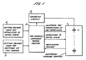
- FIG. 1 there is shown a connection-switched capacitor storage system according to the present invention, the capacitor storage system being fitted with parallel monitors.
- This system has an electrical storage portion 1, a charging circuit 2, and a charge/discharge control portion 3.
- the electrical storage portion 1 includes capacitors C.
- a set voltage used for initializing to initial state is indicated by 4.
- Another set voltage used for switching or full charge is indicated by 5.
- the electrical storage portion 1 includes the capacitors C having parallel monitors as shown in Figs. 5 and 6, as well as switches for switching the connections of the capacitors from a series combination to a parallel combination or vice versa.
- the electrical storage portion has a function of switching the connections of the parallel monitors and the capacitors C.
- the parallel monitors have a function of initializing the capacitors to their initial state.
- the charging circuit 2 controls the charging current and charges the capacitors C of the electrical storage portion 1 in plural charging modes including constant-current charging mode and trickle charging mode.
- the charge/discharge control portion 3 monitors voltages in the electrical storage portion 1, controls initializing to initial state, and switches the connections of the capacitors, thus controlling the charging circuit 2.
- the control portion 3 When the charge/discharge control portion 3 is monitoring the voltages in the electrical storage portion 1, the control portion detects the terminal voltage of each capacitor C or the terminal voltage of a typical one of the capacitors C, thus monitoring the charge state. For example, in the circuit shown in Fig. 5, the control portion 3 monitors a bypass operation signal I for initializing to initial state and a bypass operation signal F on full charge. When a initializing operation to initial state is performed and the charge/discharge control portion 3 controls the initializing operation of the electrical storage portion 1, the initializing circuit is activated. In the circuit of Fig. 5, for example, switches S1 are closed by an initialization execution signal S.
- the control portion 3 When the charge/discharge control portion 3 switches the connections of the capacitors in the electrical storage portion 1, the control portion monitors the voltages in the electrical storage portion 1, judges a switching voltage, and controls the switches, thus switching the connections of the capacitors. For instance, in the circuit shown in Fig. 6, the control portion controls the states of switches SS, SA1-SA3, and SB1-SB3, i.e., selectively opens and closes them.
- the control portion monitors the charge state of the electrical storage portion 1 to thereby judge whether a full charge has been reached. Then, the charging is stopped or the charging mode is switched to trickle charging mode. For example, in the circuit shown in Fig. 5, the bypass operation signal F on full charge is detected, and the full charge state is determined.
- the set voltage 4 for initializing to initial state is stored, for example, in a memory that holds the set voltage Vini for setting each capacitor of the electrical storage portion 1 to its initial state .
- the voltage Vini is set for each individual capacitor, if the connections of some capacitors have been switched to parallel combinations and initialization should be done.
- the set voltage 5 for switching or on full charge is stored, for example, in a memory that holds the full charge voltage Vful at which the connections of the capacitors of the electrical storage portion 1 are switched, charging is stopped, or charging mode is switched to trickle charging.
- the voltage at which the connections of the capacitors are switched may be the overall voltage of the electrical storage portion 1 or the terminal voltage of a capacitor that forms a reference. For example, in the circuit shown in Fig. 6, whenever the overall voltage of the electrical storage portion 1 reaches a given voltage, the connections are switched from combination D to combination E, from combination E to combination F, and from combination F to combination G. The charging is stopped when a full charge condition is reached. At this time, the determination may be made based on the terminal voltage of the capacitor CA1 while regarding it as a typical capacitor.
- Fig. 2 is a flowchart schematically illustrating processing performed in charging mode, the processing including execution of initializing to initial state.
- Fig. 3 is a diagram showing a method of switching the connections of shift-type, two stages of capacitors.
- Fig. 4 shows variations of the overall voltage of the electrical storage portion 1 when the connections of the two stages of capacitors of shift type are switched, variations in the terminal voltages of the capacitors, and an example of method of setting a voltage Vini used for initializing to initial state.
- the processing in the charging mode including execution of initialization starts with making a decision as to whether the voltage has reached a voltage range in which initializing to initial state can be executed (step S11).
- the initialization execution signal S for the capacitors to be initialized is kept ON for a given time (step S12).
- a decision is made as to whether the voltage has reached a voltage at which the connections should be switched (step S13). If the voltage has reached the latter voltage, only those switches which correspond to the capacitors whose connections should be switched are switched (step S14). After that, if a full charge voltage is detected (step S15), trickle charging is done, or charger stops (step S16).
- Some methods are available to switch the connections of the capacitor depending on the type of arrangement of the capacitors and on the number of stages of the capacitors.
- a shift-type, two-stage-switched capacitor arrangement consisting of four capacitors is shown in Fig. 3. Variations of the overall voltage of the electrical storage portion 1 when the connections of the capacitors are switched are shown in Fig. 4. Variations of the voltages of the capacitors are also shown in Fig. 4.
- An example of method of setting the voltage Vini used for initializing to initial state is also shown in Fig. 4.
- the connections of the capacitors are switched from a combination shown in Fig. 3(d) to a combination shown in Fig. 3(c) at point A of Fig. 4.
- the connections of the capacitors are switched from the combination shown in Fig.
- capacitors C2 and C3 are switched from a series combination to a parallel combination. Therefore, if there is a difference between the charging voltage of the capacitor C2 and the charging voltage of the capacitor C3 at this point, the higher one is discharged, while the lower one is charged. A relatively large current is supplied. The two capacitors are forced to have the same voltage in a short time.
- the capacitor bank is made up of a single capacitor, essentially the same operation is performed, though the method is different from the initializing of parallel monitors.
- the set voltage Vini set for initializing the parallel monitors to their initial state is selected to lie at point C of Fig. 4 that is close to the full charge set voltage Vful where the capacitor bank is not affected by switching of the connections of the capacitors, each capacitor will experience two operations in one charging cycle, i.e., initializing operation and equalizing operation under different conditions.
- the initializing operation is performed relatively slowly.
- the connections of the capacitors are switched almost instantly. Therefore, priority is given to the latter voltage allotment. If the initializing operation using the parallel monitor is performed more completely, then more electric power will be consumed. The result is that the charge/discharge efficiency of the electrical storage system drops.
- the voltage Vini for the parallel monitors is essentially set in such a way that the initializing operation using the parallel monitors is completed before an operation for switching the connections of the capacitors is started.
- all the capacitors C1-C4 may be initialized to their original state immediately before the connections of the capacitors are switched from the combination of Fig. 3(d) to the combination of Fig. 3(c).
- only the capacitors C2 and C3 whose connections should be switched may be initialized (point A of Fig. 4), and only capacitors C1 and C4 whose connections should be switched may be initialized (point B of Fig. 4) immediately before the connections of the capacitors are switched from the combination of Fig. 3(c) to the combination of Fig. 3(b).
- initialization is done immediately before the connections of some capacitors are switched.
- the initialization may also be done immediately after the connections of such capacitors are switched.
- Energy loss due to two operations, i.e., initializing and equalization increases in going away from the points A and B at which the connections of the capacitors are switched, such as the point C of Fig. 6. Therefore, the loss can be reduced greatly simply by bringing the initializing point close to the points A and B where the connections of the capacitors are switched instead of close to the point C of Fig. 6 (e.g., a voltage point lying in an approximately ⁇ 10% range about the voltage point at which the connections of the capacitors are switched).
- the parallel monitors for the capacitors of the electrical storage portion 1 may be set by the charge/discharge control portion 3. In addition, parallel monitors having fixed settings may also be used.
- connection-switched capacitor storage system comprising: a plurality of capacitors; parallel monitors connected in parallel with the capacitors, respectively, each of the parallel monitors acting to limit increases of the terminal voltage of a respective one of the capacitors by bypassing a charging current for the capacitor when the terminal voltage exceeds a given set voltage, the parallel monitors having a function of initializing their respective capacitors to their initial state; switching means for switching the connections of the capacitors from a series combination to a parallel combination or vice versa; and control means for controlling initializing operation of each parallel monitor to initialize the terminal voltage of a respective one of the capacitors to its initial level based on the overall voltage of the capacitors or on the terminal voltage of a given capacitor typical of the plurality of capacitors .
- the control means also acts to control the operation of the switching means to switch the connections of the capacitors.
- the control means causes the parallel monitors to initialize the terminal voltages of the capacitors near a voltage at which the connections of the capacitors are switched by the switching means. Therefore, the initialization is done at a low voltage. This reduces power loss. Decrease of the efficiency due to switching of the connections of the capacitors can be alleviated.
- Initialization using the parallel monitors is done by the control means at a voltage assumed immediately before the connections of the capacitors are switched by the switching means.
- the control means causes the parallel monitors to initialization only capacitors whose connections should be switched by the switching means. Alternatively, when all the capacitors are connected in series, initialization using the parallel monitors is done.
- the control means causes the parallel monitors to initialization their respective capacitors at a voltage assumed immediately after the connections of the capacitors are switched by the switching means. Only capacitors whose connections have not been switched by the switching means are initialized by the parallel monitors. Therefore, power loss due to initialization is reduced to a minimum. The power loss of the capacitors having the parallel monitors due to initialization is decreased. The energy efficiency of the electrical storage system having a function of switching the connections of the capacitors can be improved.
Landscapes
- Engineering & Computer Science (AREA)
- Power Engineering (AREA)
- Charge And Discharge Circuits For Batteries Or The Like (AREA)
- Direct Current Feeding And Distribution (AREA)
- Stand-By Power Supply Arrangements (AREA)
Abstract
Description
Claims (9)
- A connection-switched capacitor storage system comprising:wherein said control means causes said parallel monitors to initialize the capacitor voltages to their original level near a voltage at which the connections of the capacitors are switched by said switching means.a plurality of capacitors;parallel monitors connected in parallel with said capacitors, respectively, each of said parallel monitors acting to limit increases of a terminal voltage of a respective one of the capacitors by bypassing a charging current for the capacitor when the terminal voltage exceeds a given set voltage, the parallel monitors having a function of initializing terminal voltages of the capacitors to their initial state;switching means for switching connections of said capacitors from a series combination to a parallel combination or vice versa; andcontrol means for controlling initializing operation of each parallel monitor to initialize the terminal voltage of a respective one of the capacitors to its initial level based on an overall voltage of the capacitors or on the terminal voltage of a certain capacitor typical of said plurality of capacitors, said control means also acting to control operation of said switching means to switch the connections of the capacitors;
- The connection-switched capacitor storage system of claim 1, wherein said voltage at which the connections of the capacitors are switched by said switching means is within a ± 10% range about the voltage at which the connections of the capacitors are switched.
- The connection-switched capacitor storage system of claim 1, wherein said control means causes said parallel monitors to do initialization at a voltage assumed immediately before the connections of the capacitors are switched by said switching means.
- The connection-switched capacitor storage system of claim 3, wherein said voltage assumed immediately before the connections of the capacitors are switched by said switching means is within a -10% range from the voltage at which the connections are switched.
- The connection-switched capacitor storage system of claim 3, wherein said control means causes only capacitors whose connections should be switched by said switching means to be initialized by said parallel monitors.
- The connection-switched capacitor storage system of claim 3, wherein said control means causes said parallel monitors to do initialization when all of said capacitors have been connected in series.
- The connection-switched capacitor storage system of claim 1, wherein said control means causes said parallel monitors to do initialization at a voltage assumed immediately after the connections of the capacitors are switched by said switching means.
- The connection-switched capacitor storage system of claim 7, wherein said voltage assumed immediately after the connections of the capacitors are switched by said switching means is within a +10% range from the voltage at which the connections of the capacitors are switched.
- The connection-switched capacitor storage system of claim 7, wherein said control means causes only capacitors whose connections have not been switched by said switching means to be initialized by said parallel monitors.
Applications Claiming Priority (2)
| Application Number | Priority Date | Filing Date | Title |
|---|---|---|---|
| JP2001305944A JP2003111286A (en) | 2001-10-02 | 2001-10-02 | Bank switching capacitor power storage device with parallel monitor |
| JP2001305944 | 2001-10-02 |
Publications (2)
| Publication Number | Publication Date |
|---|---|
| EP1300933A2 true EP1300933A2 (en) | 2003-04-09 |
| EP1300933A3 EP1300933A3 (en) | 2005-06-01 |
Family
ID=19125657
Family Applications (1)
| Application Number | Title | Priority Date | Filing Date |
|---|---|---|---|
| EP02256315A Withdrawn EP1300933A3 (en) | 2001-10-02 | 2002-09-12 | Connection-switched capacitor storage system |
Country Status (4)
| Country | Link |
|---|---|
| US (1) | US6885170B2 (en) |
| EP (1) | EP1300933A3 (en) |
| JP (1) | JP2003111286A (en) |
| CN (1) | CN1333510C (en) |
Cited By (3)
| Publication number | Priority date | Publication date | Assignee | Title |
|---|---|---|---|---|
| US7180277B2 (en) | 2004-04-09 | 2007-02-20 | Maxwell Technologies, Inc. | Capacitor start-up apparatus and method with fail safe short circuit protection |
| WO2009127377A1 (en) * | 2008-04-18 | 2009-10-22 | Forschungszentrum Karlsruhe Gmbh | Method for charging and discharging a capacitor block, and charging station for charging and consumer for discharging the same |
| FR2981520A1 (en) * | 2011-10-13 | 2013-04-19 | Renault Sa | Method for managing electric energy storage battery i.e. lithium-ion battery in electric car, involves disconnecting series connection of selected storage elements, and performing parallel connection between disconnected storage elements |
Families Citing this family (16)
| Publication number | Priority date | Publication date | Assignee | Title |
|---|---|---|---|---|
| JP4169128B2 (en) * | 2003-11-11 | 2008-10-22 | 株式会社リコー | Capacitor charging semiconductor device |
| JP3781124B2 (en) * | 2004-03-29 | 2006-05-31 | 東光電気株式会社 | Capacitor power storage device |
| JP2006081321A (en) * | 2004-09-09 | 2006-03-23 | Rohm Co Ltd | Capacitor charging apparatus, semiconductor integrated circuit therefor, and capacitor charging / discharging system |
| JP4368924B2 (en) | 2005-10-19 | 2009-11-18 | 有限会社ティーエム | Power storage device using capacitor and control method thereof |
| US7656050B2 (en) * | 2007-09-27 | 2010-02-02 | William Riley | Hydroelectric pumped-storage |
| US7983021B2 (en) * | 2007-10-31 | 2011-07-19 | Corning Incorporated | Oblong electrochemical double layer capacitor |
| US8823323B2 (en) | 2009-04-16 | 2014-09-02 | Valence Technology, Inc. | Batteries, battery systems, battery submodules, battery operational methods, battery system operational methods, battery charging methods, and battery system charging methods |
| US9312705B2 (en) | 2010-12-22 | 2016-04-12 | Ge Energy Power Conversion Technology Limited | Capacitor balancing circuit and control method for an electronic device such as a multilevel power inverter |
| EP2656496B1 (en) | 2010-12-22 | 2019-09-11 | GE Energy Power Conversion Technology Limited | Mechanical arrangement of a multilevel power converter circuit |
| WO2012088447A1 (en) | 2010-12-24 | 2012-06-28 | Marc Henness | Electrical circuit for controlling electrical power to drive an inductive load |
| CN103904734B (en) * | 2014-03-10 | 2016-07-06 | 浙江工业大学 | A kind of super capacitor charge and discharge process method for handover control |
| CN106233564B (en) * | 2014-06-10 | 2019-04-23 | 株式会社Kagra | Charging method of power storage element and power storage device |
| JP6631174B2 (en) | 2015-11-06 | 2020-01-15 | 株式会社Ihi | Charge control device |
| CN106696748B (en) * | 2017-01-25 | 2019-06-28 | 华为技术有限公司 | A kind of charging pile system |
| CN112636311B (en) * | 2020-11-12 | 2021-11-12 | 中国南方电网有限责任公司超高压输电公司广州局 | Multi-port current-limiting circuit breaker based on voltage clamping principle and fault removing method |
| US12556009B2 (en) * | 2021-01-19 | 2026-02-17 | The Boeing Company | Reconfigurable battery system for efficient charging and discharging |
Family Cites Families (13)
| Publication number | Priority date | Publication date | Assignee | Title |
|---|---|---|---|---|
| CN87202343U (en) * | 1987-02-20 | 1987-10-14 | 钟国中 | Extra-reliable energy-storing device with capacitor |
| US5734205A (en) * | 1996-04-04 | 1998-03-31 | Jeol Ltd. | Power supply using batteries undergoing great voltage variations |
| US5886887A (en) | 1997-03-27 | 1999-03-23 | Integrated Memory Technologies, Inc. | Voltage multiplier with low threshold voltage sensitivity |
| JP3504871B2 (en) * | 1998-11-16 | 2004-03-08 | 株式会社岡村研究所 | Power storage device with capacitor initialization function |
| JP3761336B2 (en) | 1998-08-27 | 2006-03-29 | 株式会社パワーシステム | Capacitor power storage device |
| JP3414655B2 (en) * | 1998-11-16 | 2003-06-09 | 株式会社岡村研究所 | Series switching capacitor power supply |
| JP2000184508A (en) * | 1998-12-18 | 2000-06-30 | Nissan Diesel Motor Co Ltd | Hibrid drive system of vehicle |
| JP3487780B2 (en) * | 1999-03-01 | 2004-01-19 | 株式会社岡村研究所 | Connection switching control capacitor power supply |
| JP4079403B2 (en) * | 1999-05-17 | 2008-04-23 | 株式会社パワーシステム | Series-parallel switching capacitor power storage device |
| US6323623B1 (en) * | 1999-08-23 | 2001-11-27 | Casio Computer Co., Ltd. | Charging device and charging method thereof |
| JP3743948B2 (en) * | 1999-08-23 | 2006-02-08 | カシオ計算機株式会社 | Commercial power supply synchronous charging circuit and charging method |
| CN2393251Y (en) * | 1999-09-21 | 2000-08-23 | 陈信 | Capacity-adjustable charger |
| JP3507384B2 (en) | 1999-12-28 | 2004-03-15 | 株式会社岡村研究所 | Capacitor storage device with initialization function |
-
2001
- 2001-10-02 JP JP2001305944A patent/JP2003111286A/en active Pending
-
2002
- 2002-09-12 EP EP02256315A patent/EP1300933A3/en not_active Withdrawn
- 2002-09-29 CN CNB021435758A patent/CN1333510C/en not_active Expired - Fee Related
- 2002-10-02 US US10/263,474 patent/US6885170B2/en not_active Expired - Fee Related
Cited By (4)
| Publication number | Priority date | Publication date | Assignee | Title |
|---|---|---|---|---|
| US7180277B2 (en) | 2004-04-09 | 2007-02-20 | Maxwell Technologies, Inc. | Capacitor start-up apparatus and method with fail safe short circuit protection |
| US7880449B2 (en) | 2004-04-09 | 2011-02-01 | Maxwell Technologies, Inc. | Capacitor start-up apparatus and method with fail-safe short circuit protection |
| WO2009127377A1 (en) * | 2008-04-18 | 2009-10-22 | Forschungszentrum Karlsruhe Gmbh | Method for charging and discharging a capacitor block, and charging station for charging and consumer for discharging the same |
| FR2981520A1 (en) * | 2011-10-13 | 2013-04-19 | Renault Sa | Method for managing electric energy storage battery i.e. lithium-ion battery in electric car, involves disconnecting series connection of selected storage elements, and performing parallel connection between disconnected storage elements |
Also Published As
| Publication number | Publication date |
|---|---|
| EP1300933A3 (en) | 2005-06-01 |
| JP2003111286A (en) | 2003-04-11 |
| CN1409457A (en) | 2003-04-09 |
| US6885170B2 (en) | 2005-04-26 |
| US20030128013A1 (en) | 2003-07-10 |
| CN1333510C (en) | 2007-08-22 |
Similar Documents
| Publication | Publication Date | Title |
|---|---|---|
| EP1300933A2 (en) | Connection-switched capacitor storage system | |
| US5621300A (en) | Charging control method and apparatus for power generation system | |
| CN104348226B (en) | Battery control with block selection | |
| KR101948983B1 (en) | Battery system | |
| CN101202470B (en) | Voltage Equalization Circuit for Series Supercapacitor Banks | |
| JP3507384B2 (en) | Capacitor storage device with initialization function | |
| JP2000197276A (en) | Battery charge management device and method | |
| US6441583B1 (en) | Method, arrangement and interface system to enable electrical batteries of different kinds to be charged by means of the same charger device | |
| US6777917B2 (en) | Supercapacitor balancing method and system | |
| JP2001283932A (en) | Charge / discharge control circuit and rechargeable power supply | |
| US20090091302A1 (en) | Method of charging and discharging of supercapacitors without the use of converters or chargers | |
| JP2001309563A (en) | Building power supply system and battery device | |
| JP2000324710A (en) | Series / parallel switching type capacitor power storage device | |
| CN117543740A (en) | Storage system | |
| US20050212493A1 (en) | Capacitor system | |
| US5773957A (en) | Charge control system for set of cells | |
| JPH11355966A (en) | Battery charging and discharging devices | |
| JP3705274B2 (en) | Abnormality detection device for battery pack | |
| JP3313647B2 (en) | Capacitor charge monitoring and control device | |
| JPH0787673A (en) | Charge control method | |
| JP3414655B2 (en) | Series switching capacitor power supply | |
| JP2000323365A (en) | DC power supply | |
| JP3311670B2 (en) | Series / parallel switching power supply | |
| KR101806700B1 (en) | Power supplying apparatus for vehicle | |
| JP2001211549A (en) | Instantaneous received power control system |
Legal Events
| Date | Code | Title | Description |
|---|---|---|---|
| PUAI | Public reference made under article 153(3) epc to a published international application that has entered the european phase |
Free format text: ORIGINAL CODE: 0009012 |
|
| AK | Designated contracting states |
Kind code of ref document: A2 Designated state(s): AT BE BG CH CY CZ DE DK EE ES FI FR GB GR IE IT LI LU MC NL PT SE SK TR Designated state(s): AT BE BG CH CY CZ DE DK EE ES FI FR GB GR IE IT LI LU MC NL PT SE SK TR |
|
| AX | Request for extension of the european patent |
Extension state: AL LT LV MK RO SI |
|
| RAP1 | Party data changed (applicant data changed or rights of an application transferred) |
Owner name: KABUSHIKI KAISHA POWERSYSTEMS Owner name: OKAMURA LABORATORY INC. Owner name: ADVANCED CAPACITOR TECHNOLOGIES, INC. |
|
| PUAL | Search report despatched |
Free format text: ORIGINAL CODE: 0009013 |
|
| AK | Designated contracting states |
Kind code of ref document: A3 Designated state(s): AT BE BG CH CY CZ DE DK EE ES FI FR GB GR IE IT LI LU MC NL PT SE SK TR |
|
| AX | Request for extension of the european patent |
Extension state: AL LT LV MK RO SI |
|
| RIC1 | Information provided on ipc code assigned before grant |
Ipc: 7H 02J 7/00 B Ipc: 7H 02M 3/07 A |
|
| 17P | Request for examination filed |
Effective date: 20050816 |
|
| AKX | Designation fees paid |
Designated state(s): DE FR GB NL |
|
| 17Q | First examination report despatched |
Effective date: 20070921 |
|
| STAA | Information on the status of an ep patent application or granted ep patent |
Free format text: STATUS: THE APPLICATION IS DEEMED TO BE WITHDRAWN |
|
| 18D | Application deemed to be withdrawn |
Effective date: 20120403 |