EP1300521A1 - Connecting device for a wooden mullion-transom connection - Google Patents
Connecting device for a wooden mullion-transom connection Download PDFInfo
- Publication number
- EP1300521A1 EP1300521A1 EP02017210A EP02017210A EP1300521A1 EP 1300521 A1 EP1300521 A1 EP 1300521A1 EP 02017210 A EP02017210 A EP 02017210A EP 02017210 A EP02017210 A EP 02017210A EP 1300521 A1 EP1300521 A1 EP 1300521A1
- Authority
- EP
- European Patent Office
- Prior art keywords
- post
- anchoring
- connecting element
- bolts
- connecting device
- Prior art date
- Legal status (The legal status is an assumption and is not a legal conclusion. Google has not performed a legal analysis and makes no representation as to the accuracy of the status listed.)
- Granted
Links
Images


Classifications
-
- E—FIXED CONSTRUCTIONS
- E04—BUILDING
- E04B—GENERAL BUILDING CONSTRUCTIONS; WALLS, e.g. PARTITIONS; ROOFS; FLOORS; CEILINGS; INSULATION OR OTHER PROTECTION OF BUILDINGS
- E04B1/00—Constructions in general; Structures which are not restricted either to walls, e.g. partitions, or floors or ceilings or roofs
- E04B1/18—Structures comprising elongated load-supporting parts, e.g. columns, girders, skeletons
- E04B1/26—Structures comprising elongated load-supporting parts, e.g. columns, girders, skeletons the supporting parts consisting of wood
- E04B1/2604—Connections specially adapted therefor
Definitions
- the invention relates to a connecting device for a wood-mullion-transom connection for the front connection at least one transom to a post.
- Mullion-transom connections are known from the prior art different design known.
- Construction angle iron are used, which with the Posts and the transom are screwed.
- Modified connecting devices have additional pocket-like receiving areas in which the latch or frame can be inserted, to prevent sideways shifting.
- Constructions previously known in which the front in the end areas cross-shaped or plate-shaped elements of posts are introduced, in which by means of hook-shaped components, which are included in the bar ends, bars can be hung are.
- the invention has for its object a connecting device to create the type mentioned above, which at simple structure and simple, inexpensive to manufacture enables a high degree of pre-assembly and also by non-skilled users easily and safely use is.
- the object is characterized by the features of Main claim solved, the sub-claims show further advantageous Embodiments of the invention.
- the connecting device for a wooden post-and-beam connection to the front Connection of at least one transom to a post comprises first plate-like connecting element, which in a slot of the post is insertable, and a second plate-like connecting element, which in an end Recess of the bolt can be used.
- the two fasteners each have an anchoring element. This the two anchoring elements can be connected to one another.
- the main idea of the invention is therefore a common one to separate plate-like connecting element into two areas, which can be preassembled both on the post and on the transom are.
- the user can thus, similar to a plug-in module put the post and the bolt together and the two Connect the anchoring elements together.
- the mechanical Anchoring the two connecting elements in the post and in the bolt can be done in advance at the factory. This ensures that both the introduction the slot or the recess is carried out correctly, as well as the respective anchoring of the connecting element the post or on the transom itself.
- connection between the two anchoring elements can be done in a simple manner. Such manual measures can easily be done by less trained personnel be performed. Especially in terms of weight and the size of the posts and bars in question this makes work considerably easier. moreover Occupational safety increases because of lengthy assembly work can essentially be dispensed with.
- the bars or Posts only have to be aligned with each other and by means of the anchoring elements are connected.
- the first and / or the second anchoring element each comprises at least one bearing plate.
- the two bearing plates each extend vertically to the central plane of the respective connecting element. The Both bearing plates are thus against each other during assembly placed and lead to a correspondingly sufficient investment area. Furthermore, the two bearing surfaces provide good support, so that lateral stability is also guaranteed is.
- the bearing block with the other Anchoring element connected.
- connection of the individual connecting elements with each other is preferably done via bolts, these can for example be designed as a threaded bolt.
- Such threaded bolts can easily be screwed in by laypersons.
- these threaded bolts can be dimensioned accordingly to ensure a sufficient level of strength.
- Another advantage is that the threaded bolts are also removable so that the overall construction is disassembled for repair purposes.
- the anchoring of the two connecting elements in the post or in the bolt is preferably carried out by means of a Large number of recesses, each in the free ends the connecting elements are provided. Such recesses are used to carry out screws, bolts, dowels or Like.
- the connecting elements according to the invention are designed as sheet metal plates. You can for example, have a thickness of 10 mm.
- the production can be done by punching, laser welding or in any other way. In this respect, there is a very significant reduction in costs.
- the two anchoring elements, which preferably are also plate-shaped, can with the connecting elements are welded.
- a construction is created in which a horizontal bar 1 can be anchored to a vertical post 2 is. It is understood that the construction chosen is that the mullion and / or the transom also in other ways can be aligned. In particular, multiple connections are Cross connections or similar possible. So can instead of the assembly of a bolt shown in Fig. 6b and 7b 1 on a post 2 several bars 1 on a post 2 be attached.
- a first connecting element 3 is provided, which can be inserted into a slot in a post 2, and a second connecting element 4, which in an end Recess of a bolt 1 can be mounted, so as shown in FIGS. 5a and 5b.
- the second connecting element 4 is a second anchoring element 6, which is also designed as a bearing plate is.
- the two anchoring elements 5 and 6 are each fixed (in one piece) connected to the connecting elements 3, 4.
- bearing blocks 7, 8 and / or 9 integrally formed to the assembly with the respective To allow anchoring element 5 or 6.
- FIG second anchoring element 6 an overhead bearing block 7 on which with two recesses for the implementation of bolts 10 is provided.
- the front upper side of the first anchoring element 5 of the first connecting element 3 is corresponding provided with two recesses into which the bolts 10 are insertable.
- a lower bracket 9 of the first serves for further fastening Anchoring element 5, which to facilitate the Assembly is provided with an elongated hole through which a Bolt 10 is feasible, which, as shown, in a Recess of the second connecting element 4 can be screwed in is.
- This construction corresponds to the representation of Fig. 6a and 6b and is particularly suitable for the cases in which the latch 1 is also accessible from its underside.
- the latch as shown in Figs. 7a and 7b, possibly is difficult to access from below, the 1b construction used. It is possible on a lower bracket 8 of the second connecting element 4 pre-assemble two bolts 10. The corresponding lower recesses or bores of the first anchoring element 5 are not visible in Fig. 1b. Can be used for assembly then the pre-assembled, protruding bolts 10 in the lower end recesses of the first anchoring element 5 be plugged in. The rest of the latch is then positioned and by means of the upper bolts 10 which pass through the upper Bearing block 7 are introduced, assembled.
- FIGS. 8 and 9 show a further embodiment of the Connection device according to the invention.
- a first Connecting element 3 in a vertical slot Post 2 mounted.
- a variety of attachments are used Recesses 11 through which screws or dowels can be inserted are.
- On the first connecting element 3 is a plate-shaped, from this protruding towards a bolt 1 first anchoring element 12 attached or in one piece formed with the first connecting element 3.
- a plurality of recesses 13 are provided in the first Anchoring element 12.
- a second connecting element 4 added which also for its attachment is provided with a plurality of recesses 11 through which dowels 14 or screws can be pushed through.
- This second anchoring element 15 comprises two mutually parallel plates 16, 17, which so are spaced from each other that there is a slot between forms them into which the first anchoring element 12 can be inserted is.
- the two plates 16, 17 each have several Recesses 18, 19, which with the recesses 13 of the first anchoring element 12 are aligned. So it is possible the fastening by means of screws 20, which are in the form of Allen screws can be trained to make.
- screws 20, which are in the form of Allen screws can be trained to make.
- the recess 19 can be provided with an internal thread, while the recess 18 is designed as a smooth bore. It goes without saying that counter nuts can also be provided, to hold the screw 20.
- first connecting element 3 on both sides can be provided with a first anchoring element 12 in order to to realize bars on both sides.
- the first Connecting element 3 would then be symmetrical to one Longitudinal plane or longitudinal axis of the post built up.
- An embodiment provides that the plates 16 and 17 up and down over the plate of the second connector 4 project.
- One of the nuts 22 can also be replaced by a head of the screw 21.
- the screw 21 (Threaded rod) can be easily through the in the post 1 inserted slot in which the first connecting element 3 is included. It results thus a very significant additional increase in Rigidity of the overall construction.
Abstract
Description
Die Erfindung bezieht sich auf eine Verbindungseinrichtung für eine Holz-Pfosten-Riegel-Verbindung zum stirnseitigen Anschluss zumindest eines Riegels an einen Pfosten.The invention relates to a connecting device for a wood-mullion-transom connection for the front connection at least one transom to a post.
Pfosten-Riegel-Verbindungen sind aus dem Stand der Technik in unterschiedlicher Ausgestaltungsform bekannt. In der einfachsten Konstruktion werden Winkeleisen verwendet, welche mit dem Pfosten und dem Riegel verschraubt werden. Abgewandelte Verbindungseinrichtungen weisen zusätzliche taschenartige Aufnahmebereiche auf, in welche der Riegel oder Rähm einlegbar ist, um ein seitliches Verschieben zu verhindern. Weiterhin sind Konstruktionen vorbekannt, bei welchen stirnseitig in die Endbereiche von Pfosten kreuzförmige oder plattenförmige Elemente eingebracht werden, in welche mittels hakenförmiger Bauelemente, die in den Riegelenden aufgenommen sind, Riegel einhängbar sind.Mullion-transom connections are known from the prior art different design known. In the simplest Construction angle iron are used, which with the Posts and the transom are screwed. Modified connecting devices have additional pocket-like receiving areas in which the latch or frame can be inserted, to prevent sideways shifting. Furthermore are Constructions previously known, in which the front in the end areas cross-shaped or plate-shaped elements of posts are introduced, in which by means of hook-shaped components, which are included in the bar ends, bars can be hung are.
Die beschriebenen Konstruktionen zeichnen sich allesamt durch den Nachteil aus, dass sie zum einen eine sehr exakte handwerkliche Montage und Anpassung erfordern, um eine feste, dauerhafte, winkeltreue Konstruktion zu erzielen. Weiterhin sind einige der vorbekannten Elemente nur dazu geeignet, am oberen, stirnseitigen Ende eines Pfostens montiert zu werden.The constructions described are all characterized by the disadvantage of being a very precise craft Assembly and adjustment require a firm, permanent, Achieve angled construction. Furthermore are some of the known elements are only suitable at the top, end of a post to be mounted.
Es sind Lösungen vorgeschlagen worden, bei welchen es möglich ist, auf einfach Weise die beiden Verbindungselemente, aus welchen eine Verbindungseinrichtung aufgebaut sein kann, in einfacher Weise aneinander zu montieren. Als nachteilig hierbei kann es sich jedoch erweisen, dass es erforderlich ist, entsprechende Ausnehmungen sowohl in den Pfosten als auch in den Riegel einzubringen und nachfolgend die Verbindungselemente zu befestigen. Insbesondere bei Anwendern, die nicht über besondere handwerkliche Fähigkeiten verfügen, kann dies zu Problemen führen.Solutions have been proposed where it is possible is, in a simple way, the two connecting elements which a connecting device can be constructed in easy to assemble. As a disadvantage here however, it may prove necessary to corresponding recesses both in the posts and in insert the latch and then the connecting elements to fix. Especially for users who do not have have special manual skills, this can Cause problems.
Der Erfindung liegt die Aufgabe zugrunde, eine Verbindungseinrichtung der eingangs genannten Art zu schaffen, welche bei einfachem Aufbau und einfacher, kostengünstiger Herstellbarkeit ein hohes Maß an Vormontage ermöglicht und auch durch handwerklich nicht vorgebildete Anwender leicht und sicher zu verwenden ist.The invention has for its object a connecting device to create the type mentioned above, which at simple structure and simple, inexpensive to manufacture enables a high degree of pre-assembly and also by non-skilled users easily and safely use is.
Erfindungsgemäß wird die Aufgabe durch die Merkmale des Hauptanspruchs gelöst, die Unteransprüche zeigen weitere vorteilhafte Ausgestaltungen der Erfindung.According to the invention, the object is characterized by the features of Main claim solved, the sub-claims show further advantageous Embodiments of the invention.
Erfindungsgemäß ist somit vorgesehen, dass die Verbindungseinrichtung für eine Holz-Pfosten-Riegel-Verbindung zum stirnseitigen Anschluss zumindest eines Riegels an einen Pfosten ein erstes plattenartiges Verbindungselement umfasst, welches in einen Schlitz des Pfostens einführbar ist, sowie ein zweites plattenartiges Verbindungselement, welches in eine stirnseitige Ausnehmung des Riegels einsetzbar ist. Die beiden Verbindungselemente weisen jeweils ein Verankerungselement auf. Diese beiden Verankerungselemente sind miteinander verbindbar.According to the invention it is thus provided that the connecting device for a wooden post-and-beam connection to the front Connection of at least one transom to a post comprises first plate-like connecting element, which in a slot of the post is insertable, and a second plate-like connecting element, which in an end Recess of the bolt can be used. The two fasteners each have an anchoring element. This the two anchoring elements can be connected to one another.
Der Kerngedanke der Erfindung liegt somit darin, ein übliches plattenartiges Verbindungselement in zwei Bereiche zu trennen, die jeweils sowohl an dem Pfosten als auch an dem Riegel vormontierbar sind. Der Anwender kann somit, ähnlich einem Steckmodul den Pfosten und den Riegel zusammenstecken und die beiden Verankerungselemente miteinander verbinden. Die mechanische Verankerung der beiden Verbindungselemente in dem Pfosten und in dem Riegel kann beispielsweise werkseitig vorab erfolgen. Hierdurch ist sichergestellt, dass sowohl die Einbringung des Schlitzes bzw. der Ausnehmung in korrekter Weise erfolgt, als auch die jeweilige Verankerung des Verbindungselements an dem Pfosten bzw. an dem Riegel selbst.The main idea of the invention is therefore a common one to separate plate-like connecting element into two areas, which can be preassembled both on the post and on the transom are. The user can thus, similar to a plug-in module put the post and the bolt together and the two Connect the anchoring elements together. The mechanical Anchoring the two connecting elements in the post and in the bolt, for example, can be done in advance at the factory. This ensures that both the introduction the slot or the recess is carried out correctly, as well as the respective anchoring of the connecting element the post or on the transom itself.
Die Verbindung der beiden Verankerungselemente miteinander kann in einfacher Weise erfolgen. Derartige handwerkliche Maßnahmen können auch von weniger geschultem Personal leicht durchgeführt werden. Insbesondere im Hinblick auf das Gewicht und die Größe der zur Rede stehenden Pfosten und Riegel ergibt sich dadurch eine ganz erhebliche Arbeitserleichterung. Zudem steigt die Arbeitssicherheit, da auf langwierigere Montagearbeiten im Wesentlichen verzichtet werden kann. Die Riegel bzw. Pfosten müssen nur noch zueinander ausgerichtet und mittels der Verankerungselemente verbunden werden.The connection between the two anchoring elements can be done in a simple manner. Such manual measures can easily be done by less trained personnel be performed. Especially in terms of weight and the size of the posts and bars in question this makes work considerably easier. moreover Occupational safety increases because of lengthy assembly work can essentially be dispensed with. The bars or Posts only have to be aligned with each other and by means of the anchoring elements are connected.
In einer besonders günstigen Weiterbildung der Erfindung ist vorgesehen, dass das erste und/oder das zweite Verankerungselement jeweils zumindest eine Lagerplatte umfasst. Bevorzugterweise erstrecken sich die beiden Lagerplatten jeweils senkrecht zur Mittelebene des jeweiligen Verbindungselements. Die beiden Lagerplatten werden somit bei der Montage gegeneinander gelegt und führen zu einer entsprechend ausreichenden Anlagefläche. Weiterhin bilden die beiden Lagerflächen eine gute Abstützung, so dass auch die seitliche Stabilität gewährleistet ist.In a particularly favorable development of the invention provided that the first and / or the second anchoring element each comprises at least one bearing plate. preferably, the two bearing plates each extend vertically to the central plane of the respective connecting element. The Both bearing plates are thus against each other during assembly placed and lead to a correspondingly sufficient investment area. Furthermore, the two bearing surfaces provide good support, so that lateral stability is also guaranteed is.
Um nicht nur eine flächige Anlage der beiden Verbindungselemente aneinander zu gewährleisten, sondern um auch insbesondere vertikale Kräfte aufnehmen zu können, ist es besonders günstig, wenn an dem ersten und/oder dem zweiten Verankerungselement zumindest ein Lagerbock angeordnet bzw. einstückig mit diesem ausgebildet ist. Es ist somit möglich, den Lagerbock auf das jeweils andere Verankerungselement aufzulegen oder diesen gegen das Verankerungselement anzulegen. Bereits hierdurch ergibt sich ein zusätzliches Maß an Festigkeit, welches insbesondere auch während des Montagevorganges wichtig ist. Bevorzugterweise wird der Lagerbock mit dem jeweils anderen Verankerungselement verbunden.Not just a two-dimensional contact between the two connecting elements to ensure each other, but also in particular to be able to absorb vertical forces, it is particularly favorable if on the first and / or the second anchoring element at least one bearing block arranged or in one piece with this is trained. It is thus possible to use the pedestal to be placed on the other anchoring element or to place this against the anchoring element. Already through this there is an additional level of strength, which is especially important during the assembly process. Preferably, the bearing block with the other Anchoring element connected.
Erfindungsgemäß steht somit eine in drei Dimensionen stabile Verbindung der beiden Verbindungselemente zur Verfügung, so dass ausreichende Kräfte aufgenommen werden können, um die Gesamtkonstruktion sicher und stabil zu machen.According to the invention there is thus a stable in three dimensions Connection of the two connecting elements available, so that sufficient forces can be absorbed to the overall construction to make it safe and stable.
Die Verbindung der einzelnen Verbindungselemente untereinander erfolgt bevorzugterweise über Bolzen, diese können beispielsweise als Gewindebolzen ausgebildet sein. Derartige Gewindebolzen sind in einfacher Weise auch durch Laien einschraubbar. Weiterhin können diese Gewindebolzen entsprechend dimensioniert werden, um ein ausreichendes Maß an Festigkeit zu gewährleisten. Ein weiterer Vorteil besteht darin, dass die Gewindebolzen auch demontierbar sind, so dass die Gesamtkonstruktion zu Reparaturzwecken auseinandernehmbar ist.The connection of the individual connecting elements with each other is preferably done via bolts, these can for example be designed as a threaded bolt. Such threaded bolts can easily be screwed in by laypersons. Furthermore, these threaded bolts can be dimensioned accordingly to ensure a sufficient level of strength. Another advantage is that the threaded bolts are also removable so that the overall construction is disassembled for repair purposes.
Zur Stabilisierung kann es vorteilhaft sein, wenn nebeneinander jeweils mehrere derartige Bolzen bzw. Gewindebolzen vorgesehen sind.For stabilization, it can be advantageous if next to each other several such bolts or threaded bolts are provided are.
Die Verankerung der beiden Verbindungselemente in dem Pfosten bzw. in dem Riegel erfolgt bevorzugterweise mittels einer Vielzahl von Ausnehmungen, welche jeweils in den freien Enden der Verbindungselemente vorgesehen sind. Derartige Ausnehmungen dienen zur Durchführung von Schrauben, Bolzen, Dübeln oder Ähnlichem.The anchoring of the two connecting elements in the post or in the bolt is preferably carried out by means of a Large number of recesses, each in the free ends the connecting elements are provided. Such recesses are used to carry out screws, bolts, dowels or Like.
Besonders günstig ist es, wenn die erfindungsgemäßen Verbindungselemente als Blechplatten ausgebildet sind. Sie können beispielsweise eine Dicke von 10 mm haben. Die Herstellung kann durch Stanzen, Laserschweißen oder auf andere Weise erfolgen. Insofern ergibt sich eine ganz erhebliche Kostenreduzierung. Die beiden Verankerungselemente, welche bevorzugterweise ebenfalls plattenförmig ausgestaltet sind, können mit den Verbindungselementen verschweißt sein. Es ist jedoch auch möglich, andere Ausgestaltungs- und Herstellungsverfahren zu wählen, beispielsweise mittels stranggepresster Profile oder in Form von gegossenen Elementen.It is particularly favorable if the connecting elements according to the invention are designed as sheet metal plates. You can for example, have a thickness of 10 mm. The production can be done by punching, laser welding or in any other way. In this respect, there is a very significant reduction in costs. The two anchoring elements, which preferably are also plate-shaped, can with the connecting elements are welded. However, it is also possible to use other design and manufacturing processes choose, for example using extruded profiles or in the form of cast elements.
Im Folgenden wird die Erfindung anhand von Ausführungsbeispielen in Verbindung mit der Zeichnung beschrieben. Dabei zeigt:
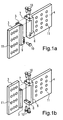
- Fig. 1a
- eine perspektivische Ansicht eines ersten Ausführungsbeispiels zweier zueinander passender Verbindungselemente,
- Fig. 1b
- eine perspektivische Ausgestaltung eines zweiten Ausführungsbeispiels zweier zueinander passender Verbindungselemente,
- Fig. 2a
- eine perspektivische Ansicht eines Teilbereichs eines Riegels und eines Pfostens mit der in Fig. 1a gezeigten Konstruktion,
- Fig. 2b
- eine Ansicht analog Fig. 2a mit der in Fig. 1b gezeigten Konstruktion,
- Fig. 3a
- Ansichten des zweiten Verbindungselements gemäß der Ausgestaltung von Fig. 1a,
- Fig. 3b
- Ansichten analog Fig. 3a, gemäß dem Ausführungsbeispiel der Fig. 1b,
- Fig. 4a
- Ansichten des ersten Verbindungselements gemäß der Ausgestaltung zu Fig. 1a,
- Fig. 4b
- Ansichten des Verbindungselements analog Fig. 4a, jedoch in Darstellung des Ausführungsbeispiels der Fig. 1b,
- Fig. 5a
- eine stirnseitige Ansicht eines Riegels zur Aufnahme des zweiten Verbindungselements,
- Fig. 5b
- eine stirnseitige Ansicht des Riegels, analog Fig. 5a, mit eingesetztem Verbindungselement,
- Fig. 6a und 6b
- perspektivische Darstellungen der Montage und Verwendung des Ausführungsbeispiels der Fig. 1a,
- Fig. 7a und 7b
- Ansichten analog Fig. 6a und 6b des in Fig. 1b dargestellten Ausführungsbeispiels,
- Fig. 8
- eine perspektivische, stark vereinfachte Ansicht eines weiteren Ausführungsbeispiels der Erfindung, und
- Fig. 9
- eine Draufsicht auf die in Fig. 1 gezeigte Anordnung.
- Fig. 1a
- 2 shows a perspective view of a first exemplary embodiment of two connecting elements which match one another,
- Fig. 1b
- 3 shows a perspective configuration of a second exemplary embodiment of two connecting elements which match one another,
- Fig. 2a
- 1 shows a perspective view of a partial region of a transom and a post with the construction shown in FIG. 1a,
- Fig. 2b
- 2a with the construction shown in FIG. 1b,
- Fig. 3a
- Views of the second connecting element according to the embodiment of Fig. 1a,
- Fig. 3b
- 3a, according to the embodiment of FIG. 1b,
- Fig. 4a
- Views of the first connecting element according to the embodiment of Fig. 1a,
- Fig. 4b
- Views of the connecting element analogous to FIG. 4a, but showing the exemplary embodiment of FIG. 1b,
- Fig. 5a
- an end view of a bolt for receiving the second connecting element,
- Fig. 5b
- 5 shows an end view of the bolt, analogous to FIG. 5a, with the connecting element inserted,
- 6a and 6b
- perspective representations of the assembly and use of the embodiment of Fig. 1a,
- 7a and 7b
- 6a and 6b of the embodiment shown in FIG. 1b,
- Fig. 8
- a perspective, greatly simplified view of another embodiment of the invention, and
- Fig. 9
- a plan view of the arrangement shown in Fig. 1.
In den nachfolgenden Ausführungsbeispielen sind gleiche Teile jeweils mit gleichen Bezugsziffern bezeichnet.The same parts are used in the following exemplary embodiments each with the same reference numerals.
Erfindungsgemäß ist eine Konstruktion geschaffen, in welcher
ein horizontaler Riegel 1 an einem vertikalen Pfosten 2 verankerbar
ist. Es versteht sich, dass die Konstruktion so gewählt
ist, dass der Pfosten und/oder der Riegel auch in anderer Weise
ausgerichtet sein können. Insbesondere sind mehrfache Anbindungen,
Kreuzverbindungen oder Ähnliches möglich. So können
an Stelle der in Fig. 6b und 7b gezeigten Montage eines Riegels
1 an einem Pfosten 2 mehrere Riegel 1 an einem Pfosten 2
befestigt werden.According to the invention, a construction is created in which
a
Erfindungsgemäß ist ein erstes Verbindungselement 3 vorgesehen,
welches in einen Schlitz eines Pfostens 2 einsetzbar ist,
sowie ein zweites Verbindungselement 4, welches in eine stirnseitige
Ausnehmung eines Riegels 1 montiert werden kann, so
wie dies die Fig. 5a und 5b zeigen.According to the invention, a first connecting
Das erste Verbindungselement 3, welches, ebenso wie das zweite
Verbindungselement 4, plattenförmig ausgebildet ist und eine
Vielzahl von Ausnehmungen 11 zur Befestigung aufweist, ist mit
einem ersten Verankerungselement 5, welches in Form einer Lagerplatte
ausgestaltet ist, versehen. In analoger Weise weist
das zweite Verbindungselement 4 ein zweites Verankerungselement
6 auf, welches ebenfalls als Lagerplatte ausgestaltet
ist. Die beiden Verankerungselemente 5 und 6 sind jeweils fest
(einstückig) mit den Verbindungselementen 3, 4 verbunden.The first connecting
An dem Verankerungselement 5 bzw. 6 sind Lagerböcke 7, 8
und/oder 9 einstückig ausgebildet, um die Montage mit dem jeweiligen
Verankerungselement 5 bzw. 6 zu ermöglichen.On the
Bei dem in Fig. 1a gezeigten Ausführungsbeispiel weist das
zweite Verankerungselement 6 einen oben liegenden Lagerbock 7
auf, welcher mit zwei Ausnehmungen zur Durchführung von Bolzen
10 versehen ist. Die stirnseitige Oberseite des ersten Verankerungselements
5 des ersten Verbindungselements 3 ist entsprechend
mit zwei Ausnehmungen versehen, in welche die Bolzen
10 einführbar sind. In the exemplary embodiment shown in FIG
Zur weiteren Befestigung dient ein unterer Lagerbock 9 des ersten
Verankerungselements 5, welcher zur Erleichterung der
Montage mit einem Langloch versehen ist, durch welches ein
Bolzen 10 durchführbar ist, welcher, wie dargestellt, in eine
Ausnehmung des zweiten Verbindungselements 4 einschraubbar
ist. Diese Konstruktion entspricht der Darstellung der Fig. 6a
und 6b und eignet sich insbesondere für die Fälle, bei welchen
der Riegel 1 auch von seiner Unterseite zugänglich ist.A lower bracket 9 of the first serves for further
Sofern der Riegel, wie in den Fig. 7a und 7b gezeigt, möglicherweise
von unten schlecht zugänglich ist, kann die in Fig.
1b gezeigte Konstruktion zur Anwendung kommen. Dabei ist es
möglich, an einem unteren Lagerbock 8 des zweiten Verbindungselements
4 zwei Bolzen 10 vorzumontieren. Die entsprechenden
unteren Ausnehmungen oder Bohrungen des ersten Verankerungselements
5 sind in Fig. 1b nicht sichtbar. Zur Montage können
dann die vormontierten, vorstehenden Bolzen 10 in die unteren
stirnseitigen Ausnehmungen des ersten Verankerungselements 5
eingesteckt werden. Nachfolgend wird der Riegel restlich positioniert
und mittels der oberen Bolzen 10, die durch den oberen
Lagerbock 7 eingebracht werden, montiert.If the latch, as shown in Figs. 7a and 7b, possibly
is difficult to access from below, the
1b construction used. It is
possible on a
Bei der in Fig. 1b gezeigten Ausgestaltungsform (siehe auch
Fig. 2b, 3b und 4b) ist es möglich, lediglich eine stirnseitige
Ausnehmung an dem Riegel 1 vorzusehen, auf seitliche Ausnehmungen,
wie bei dem in Fig. 5a gezeigten Ausführungsbeispiel,
kann verzichtet werden. Insofern ergibt sich möglicherweise
auch eine verbesserte optische Gesamtansicht.In the embodiment shown in Fig. 1b (see also
2b, 3b and 4b) it is possible to have only one end face
Provide recess on the
Die Fig. 8 und 9 zeigen ein weiteres Ausführungsbeispiel der
erfindungsgemäßen Verbindungseinrichtung. Hierbei ist ein erstes
Verbindungselement 3 in einem vertikalen Schlitz eines
Pfostens 2 montiert. Zur Befestigung dienen eine Vielzahl von
Ausnehmungen 11, durch welche Schrauben oder Dübel durchsteckbar
sind. An dem ersten Verbindungselement 3 ist ein plattenförmiges,
von diesem in Richtung auf einen Riegel 1 vorstehendes
erstes Verankerungselement 12 befestigt bzw. einstückig
mit dem ersten Verbindungselement 3 ausgebildet. In dem ersten
Verankerungselement 12 sind mehrere Ausnehmungen 13 vorgesehen.8 and 9 show a further embodiment of the
Connection device according to the invention. Here is a first
Zur lösbaren Lagerung des Riegels 1 an dem Pfosten 2 ist, wie
oben beschrieben, in dem Riegel 1 ein zweites Verbindungselement
4 aufgenommen, welches zu seiner Befestigung ebenfalls
mit einer Vielzahl von Ausnehmungen 11 versehen ist, durch
welche Dübel 14 oder Schrauben durchsteckbar sind.For releasable storage of the
Wie sich insbesondere aus der Darstellung der Fig. 9 ergibt,
ist ein zweites Verankerungselement 15 an dem zweiten Verbindungselement
4 befestigt. Dieses zweite Verankerungselement 15
umfasst zwei zueinander parallele Platten 16, 17, welche so
zueinander beabstandet sind, dass sich ein Schlitz zwischen
ihnen bildet, in welchen das erste Verankerungselement 12 einschiebbar
ist. Die beiden Platten 16, 17 weisen jeweils mehrere
Ausnehmungen 18, 19 auf, die mit den Ausnehmungen 13 des
ersten Verankerungselements 12 fluchten. Somit ist es möglich,
die Befestigung mittels Schrauben 20, welche in Form von Imbus-Schrauben
ausgebildet sein können, vorzunehmen. Hierzu
kann die Ausnehmung 19 mit einem Innengewinde versehen sein,
während die Ausnehmung 18 als glatte Bohrung ausgebildet ist.
Es versteht sich, dass auch Gegen-Muttern vorgesehen sein können,
um die Schraube 20 zu halten.As can be seen in particular from the illustration in FIG. 9,
is a
Bei der beschriebenen Ausgestaltung erweist es sich als vorteilhaft, dass sich eine sehr einfache Montage ergibt. Wie auch bei den vorangehend beschriebenen Ausführungsbeispielen ist es besonders vorteilhaft, dass die Gebäudekonstruktion leicht demontierbar ist, sei es zum vollständigen Abbau des Gebäudes oder zu dessen Umbau.In the embodiment described, it proves to be advantageous that there is a very simple assembly. How also in the exemplary embodiments described above it is particularly advantageous that the building construction is easy to dismantle, be it to completely dismantle the Building or for its conversion.
Gerade die zuletzt beschriebene Ausgestaltungsform zeichnet
sich dadurch aus, dass wenig Holzarbeiten erforderlich sind,
da lediglich ein an seinem freien Ende abgestufter Schlitz in
den Riegel eingefräst werden muss. Die Einbringung der zusätzlichen
Bohrungen in den Riegel, die zur Durchführung der
Schraube 20 erforderlich sind, sind ebenfalls einfach und kostengünstig
realisierbar.It is the last embodiment described that draws
is characterized by the fact that little woodwork is required,
because only one slot in
the bolt must be milled. The introduction of additional
Holes in the latch that are used to carry out the
Es versteht sich, dass bei dem in den Fig. 8 und 9 gezeigten
Ausführungsbeispiel das erste Verbindungselement 3 beidseitig
mit einem ersten Verankerungselement 12 versehen sein kann, um
den beidseitigen Anschluss von Riegeln zu realisieren. Das erste
Verbindungselement 3 wäre dann symmetrisch zu einer
Längsebene oder Längsachse des Pfostens aufgebaut.It is understood that the one shown in FIGS. 8 and 9
Embodiment the first connecting
In einer günstigen Weiterbildung des in den Fig. 8 und 9 gezeigten
Ausführungsbeispiels ist vorgesehen, dass die Platten
16 und 17 nach oben und unten über die Platte des zweiten Verbindungselements
4 vorstehen. Somit bildet sich eine Anlagefläche,
mittels der eine Schraube 21 bzw. eine Gewindestange
abgestützt werden kann. Diese dient als Zugelement, um zwei
benachbarte zweite Verbindungselemente 4 zusätzlich gegeneinander
zu verspannen und die Biegesteifigkeit zu erhöhen. Hierzu
sind beidseitig jeweils Muttern 22 auf die Schraube 21 bzw.
die Gewindestange aufgebracht. Eine der Muttern 22 kann auch
durch einen Kopf der Schraube 21 ersetzt sein. Die Schraube 21
(Gewindestange) kann in einfacher Weise durch den in den Pfosten
1 eingebrachten Schlitz, in welchem das erste Verbindungselement
3 aufgenommen ist, durchgeführt werden. Es ergibt
sich somit eine ganz erhebliche zusätzliche Steigerung der
Steifigkeit der Gesamtkonstruktion. In a favorable further development of the one shown in FIGS. 8 and 9
An embodiment provides that the
Die Erfindung ist nicht auf die gezeigten Ausführungsbeispiele beschränkt, vielmehr ergeben sich im Rahmen der Erfindung vielfältige Abwandlungs- und Modifikationsmöglichkeiten.The invention is not based on the exemplary embodiments shown limited, rather arise within the scope of the invention diverse options for modification and modification.
Claims (10)
Applications Claiming Priority (2)
| Application Number | Priority Date | Filing Date | Title |
|---|---|---|---|
| DE10149537A DE10149537B4 (en) | 2001-10-08 | 2001-10-08 | Connecting device for a timber post-tie connection |
| DE10149537 | 2001-10-08 |
Publications (2)
| Publication Number | Publication Date |
|---|---|
| EP1300521A1 true EP1300521A1 (en) | 2003-04-09 |
| EP1300521B1 EP1300521B1 (en) | 2009-12-16 |
Family
ID=7701763
Family Applications (1)
| Application Number | Title | Priority Date | Filing Date |
|---|---|---|---|
| EP02017210A Expired - Lifetime EP1300521B1 (en) | 2001-10-08 | 2002-07-31 | Connecting device for a wooden mullion-transom connection |
Country Status (4)
| Country | Link |
|---|---|
| EP (1) | EP1300521B1 (en) |
| AT (1) | ATE452251T1 (en) |
| DE (2) | DE10149537B4 (en) |
| DK (1) | DK1300521T3 (en) |
Cited By (2)
| Publication number | Priority date | Publication date | Assignee | Title |
|---|---|---|---|---|
| EP1736606A1 (en) | 2005-06-23 | 2006-12-27 | Neue Holzbau AG Lungern | Resistant to bending and pluggable connection for structural elements |
| US10422123B2 (en) * | 2016-11-07 | 2019-09-24 | Simpson Strong-Tie Company Inc. | Concealed joist tie with sloped center flange |
Families Citing this family (1)
| Publication number | Priority date | Publication date | Assignee | Title |
|---|---|---|---|---|
| DE10352992B4 (en) * | 2003-11-13 | 2008-11-13 | Bohrenkämper, Gustav | wood connectors |
Citations (3)
| Publication number | Priority date | Publication date | Assignee | Title |
|---|---|---|---|---|
| US4299509A (en) * | 1978-08-31 | 1981-11-10 | Streif Ohg | Beam connector |
| EP0130145A1 (en) * | 1983-05-24 | 1985-01-02 | BSB Holzkonstruktionen AG | Fastening joint for wooden beams |
| DE20022076U1 (en) * | 2000-12-29 | 2001-03-01 | Heidemann Modular Space System | Connection system for structural elements in timber construction |
Family Cites Families (3)
| Publication number | Priority date | Publication date | Assignee | Title |
|---|---|---|---|---|
| DE3401303C2 (en) * | 1984-01-16 | 1986-01-16 | Jan Dipl.-Ing. 8000 München Forster | Fasteners for wooden components |
| DE3641799A1 (en) * | 1986-12-06 | 1988-06-16 | Gustav Bohrenkaemper | Device which is intended for connecting two wooden beams |
| DE20011793U1 (en) * | 2000-07-07 | 2000-09-28 | Bohrenkaemper Gustav | Connecting fitting |
-
2001
- 2001-10-08 DE DE10149537A patent/DE10149537B4/en not_active Expired - Fee Related
-
2002
- 2002-07-31 EP EP02017210A patent/EP1300521B1/en not_active Expired - Lifetime
- 2002-07-31 DE DE50214091T patent/DE50214091D1/en not_active Expired - Lifetime
- 2002-07-31 DK DK02017210.2T patent/DK1300521T3/en active
- 2002-07-31 AT AT02017210T patent/ATE452251T1/en active
Patent Citations (3)
| Publication number | Priority date | Publication date | Assignee | Title |
|---|---|---|---|---|
| US4299509A (en) * | 1978-08-31 | 1981-11-10 | Streif Ohg | Beam connector |
| EP0130145A1 (en) * | 1983-05-24 | 1985-01-02 | BSB Holzkonstruktionen AG | Fastening joint for wooden beams |
| DE20022076U1 (en) * | 2000-12-29 | 2001-03-01 | Heidemann Modular Space System | Connection system for structural elements in timber construction |
Cited By (2)
| Publication number | Priority date | Publication date | Assignee | Title |
|---|---|---|---|---|
| EP1736606A1 (en) | 2005-06-23 | 2006-12-27 | Neue Holzbau AG Lungern | Resistant to bending and pluggable connection for structural elements |
| US10422123B2 (en) * | 2016-11-07 | 2019-09-24 | Simpson Strong-Tie Company Inc. | Concealed joist tie with sloped center flange |
Also Published As
| Publication number | Publication date |
|---|---|
| DE10149537A1 (en) | 2003-06-05 |
| DE50214091D1 (en) | 2010-01-28 |
| DE10149537B4 (en) | 2005-09-22 |
| DK1300521T3 (en) | 2010-04-19 |
| ATE452251T1 (en) | 2010-01-15 |
| EP1300521B1 (en) | 2009-12-16 |
Similar Documents
| Publication | Publication Date | Title |
|---|---|---|
| DE2618442C2 (en) | Support for a railing or the like | |
| DE1927040C3 (en) | Device for the end connection of an extruded profile to an extruded profile running through at least at the connection point, in particular made of light metal, plastic or the like | |
| DE102009012438B4 (en) | pinheader | |
| EP0436869A2 (en) | Butt joint junction between column and crossbar of a supporting structure of or for a façade wall | |
| DE2525791B2 (en) | ARRANGEMENT FOR CONNECTING TWO EACH OTHER PLATE OR ROD ELEMENTS | |
| DE1003937B (en) | Railing construction, especially for stairs | |
| DE2838163A1 (en) | DETACHABLE FRAME SYSTEM | |
| EP0976891B1 (en) | Construction system | |
| EP1300521A1 (en) | Connecting device for a wooden mullion-transom connection | |
| DE19623870C1 (en) | Device for releasable connection of two profile bars at different angles to each other | |
| DE4447208C2 (en) | Hook carrier system | |
| DE3839369A1 (en) | Connecting element and process for connecting solid-wood or glued-wood beams in the same plane | |
| DE3442231A1 (en) | ROOM CONSTRUCTION | |
| EP1251478A2 (en) | Strut structure | |
| DE10140878B4 (en) | Connection device for a wood-post-transom connection | |
| DE19604665A1 (en) | Cross connector for profiles in groove-locking design | |
| EP1491696A2 (en) | System for joining profiles | |
| WO1986005667A1 (en) | Hollow profile material for the construction of support mounts and frames | |
| DE3829424C2 (en) | ||
| DE102005005807A1 (en) | Fitting device for adjusting window frames/door frames in a structural opening has fixing elements and a threaded sleeve | |
| DE19622306A1 (en) | Facade system with polygonal sections for cladding buildings | |
| DE3721869A1 (en) | CONNECTING DEVICE | |
| DE2410211A1 (en) | COMBINATION FURNITURE | |
| DE19732938C1 (en) | Steel door frame with threshold | |
| DE102010019385B4 (en) | Plug foot holder for a platform, stage and grandstand construction and such a construction |
Legal Events
| Date | Code | Title | Description |
|---|---|---|---|
| PUAI | Public reference made under article 153(3) epc to a published international application that has entered the european phase |
Free format text: ORIGINAL CODE: 0009012 |
|
| AK | Designated contracting states |
Kind code of ref document: A1 Designated state(s): AT BE BG CH CY CZ DE DK EE ES FI FR GB GR IE IT LI LU MC NL PT SE SK TR |
|
| AX | Request for extension of the european patent |
Extension state: AL LT LV MK RO SI |
|
| 17P | Request for examination filed |
Effective date: 20030729 |
|
| AKX | Designation fees paid |
Designated state(s): AT BE BG CH CY CZ DE DK EE ES FI FR GB GR IE IT LI LU MC NL PT SE SK TR |
|
| RAP1 | Party data changed (applicant data changed or rights of an application transferred) |
Owner name: HEIDEMANN, MAREN |
|
| 17Q | First examination report despatched |
Effective date: 20061204 |
|
| GRAP | Despatch of communication of intention to grant a patent |
Free format text: ORIGINAL CODE: EPIDOSNIGR1 |
|
| GRAS | Grant fee paid |
Free format text: ORIGINAL CODE: EPIDOSNIGR3 |
|
| GRAA | (expected) grant |
Free format text: ORIGINAL CODE: 0009210 |
|
| AK | Designated contracting states |
Kind code of ref document: B1 Designated state(s): AT BE BG CH CY CZ DE DK EE ES FI FR GB GR IE IT LI LU MC NL PT SE SK TR |
|
| REG | Reference to a national code |
Ref country code: GB Ref legal event code: FG4D Free format text: NOT ENGLISH |
|
| REG | Reference to a national code |
Ref country code: CH Ref legal event code: EP |
|
| REG | Reference to a national code |
Ref country code: IE Ref legal event code: FG4D |
|
| REG | Reference to a national code |
Ref country code: SE Ref legal event code: TRGR |
|
| REF | Corresponds to: |
Ref document number: 50214091 Country of ref document: DE Date of ref document: 20100128 Kind code of ref document: P |
|
| REG | Reference to a national code |
Ref country code: CH Ref legal event code: NV Representative=s name: KELLER & PARTNER PATENTANWAELTE AG WINTERTHUR |
|
| REG | Reference to a national code |
Ref country code: DK Ref legal event code: T3 |
|
| REG | Reference to a national code |
Ref country code: NL Ref legal event code: VDEP Effective date: 20091216 |
|
| PG25 | Lapsed in a contracting state [announced via postgrant information from national office to epo] |
Ref country code: FI Free format text: LAPSE BECAUSE OF FAILURE TO SUBMIT A TRANSLATION OF THE DESCRIPTION OR TO PAY THE FEE WITHIN THE PRESCRIBED TIME-LIMIT Effective date: 20091216 |
|
| REG | Reference to a national code |
Ref country code: IE Ref legal event code: FD4D |
|
| PG25 | Lapsed in a contracting state [announced via postgrant information from national office to epo] |
Ref country code: NL Free format text: LAPSE BECAUSE OF FAILURE TO SUBMIT A TRANSLATION OF THE DESCRIPTION OR TO PAY THE FEE WITHIN THE PRESCRIBED TIME-LIMIT Effective date: 20091216 Ref country code: EE Free format text: LAPSE BECAUSE OF FAILURE TO SUBMIT A TRANSLATION OF THE DESCRIPTION OR TO PAY THE FEE WITHIN THE PRESCRIBED TIME-LIMIT Effective date: 20091216 Ref country code: BG Free format text: LAPSE BECAUSE OF FAILURE TO SUBMIT A TRANSLATION OF THE DESCRIPTION OR TO PAY THE FEE WITHIN THE PRESCRIBED TIME-LIMIT Effective date: 20100316 Ref country code: ES Free format text: LAPSE BECAUSE OF FAILURE TO SUBMIT A TRANSLATION OF THE DESCRIPTION OR TO PAY THE FEE WITHIN THE PRESCRIBED TIME-LIMIT Effective date: 20100327 Ref country code: IE Free format text: LAPSE BECAUSE OF FAILURE TO SUBMIT A TRANSLATION OF THE DESCRIPTION OR TO PAY THE FEE WITHIN THE PRESCRIBED TIME-LIMIT Effective date: 20091216 Ref country code: PT Free format text: LAPSE BECAUSE OF FAILURE TO SUBMIT A TRANSLATION OF THE DESCRIPTION OR TO PAY THE FEE WITHIN THE PRESCRIBED TIME-LIMIT Effective date: 20100416 |
|
| PG25 | Lapsed in a contracting state [announced via postgrant information from national office to epo] |
Ref country code: CZ Free format text: LAPSE BECAUSE OF FAILURE TO SUBMIT A TRANSLATION OF THE DESCRIPTION OR TO PAY THE FEE WITHIN THE PRESCRIBED TIME-LIMIT Effective date: 20091216 Ref country code: SK Free format text: LAPSE BECAUSE OF FAILURE TO SUBMIT A TRANSLATION OF THE DESCRIPTION OR TO PAY THE FEE WITHIN THE PRESCRIBED TIME-LIMIT Effective date: 20091216 |
|
| PLBE | No opposition filed within time limit |
Free format text: ORIGINAL CODE: 0009261 |
|
| STAA | Information on the status of an ep patent application or granted ep patent |
Free format text: STATUS: NO OPPOSITION FILED WITHIN TIME LIMIT |
|
| PG25 | Lapsed in a contracting state [announced via postgrant information from national office to epo] |
Ref country code: CY Free format text: LAPSE BECAUSE OF FAILURE TO SUBMIT A TRANSLATION OF THE DESCRIPTION OR TO PAY THE FEE WITHIN THE PRESCRIBED TIME-LIMIT Effective date: 20091216 Ref country code: GR Free format text: LAPSE BECAUSE OF FAILURE TO SUBMIT A TRANSLATION OF THE DESCRIPTION OR TO PAY THE FEE WITHIN THE PRESCRIBED TIME-LIMIT Effective date: 20100317 |
|
| 26N | No opposition filed |
Effective date: 20100917 |
|
| BERE | Be: lapsed |
Owner name: HEIDEMANN, MAREN Effective date: 20100731 |
|
| PG25 | Lapsed in a contracting state [announced via postgrant information from national office to epo] |
Ref country code: MC Free format text: LAPSE BECAUSE OF NON-PAYMENT OF DUE FEES Effective date: 20100731 |
|
| PG25 | Lapsed in a contracting state [announced via postgrant information from national office to epo] |
Ref country code: IT Free format text: LAPSE BECAUSE OF FAILURE TO SUBMIT A TRANSLATION OF THE DESCRIPTION OR TO PAY THE FEE WITHIN THE PRESCRIBED TIME-LIMIT Effective date: 20091216 |
|
| REG | Reference to a national code |
Ref country code: FR Ref legal event code: ST Effective date: 20110331 |
|
| PG25 | Lapsed in a contracting state [announced via postgrant information from national office to epo] |
Ref country code: FR Free format text: LAPSE BECAUSE OF NON-PAYMENT OF DUE FEES Effective date: 20100802 |
|
| PG25 | Lapsed in a contracting state [announced via postgrant information from national office to epo] |
Ref country code: BE Free format text: LAPSE BECAUSE OF NON-PAYMENT OF DUE FEES Effective date: 20100731 |
|
| PG25 | Lapsed in a contracting state [announced via postgrant information from national office to epo] |
Ref country code: LU Free format text: LAPSE BECAUSE OF NON-PAYMENT OF DUE FEES Effective date: 20100731 |
|
| PG25 | Lapsed in a contracting state [announced via postgrant information from national office to epo] |
Ref country code: TR Free format text: LAPSE BECAUSE OF FAILURE TO SUBMIT A TRANSLATION OF THE DESCRIPTION OR TO PAY THE FEE WITHIN THE PRESCRIBED TIME-LIMIT Effective date: 20091216 |
|
| REG | Reference to a national code |
Ref country code: CH Ref legal event code: PCAR Free format text: NEW ADDRESS: EIGERSTRASSE 2 POSTFACH, 3000 BERN 14 (CH) |
|
| PGFP | Annual fee paid to national office [announced via postgrant information from national office to epo] |
Ref country code: GB Payment date: 20170724 Year of fee payment: 16 Ref country code: DE Payment date: 20170731 Year of fee payment: 16 Ref country code: CH Payment date: 20170724 Year of fee payment: 16 |
|
| PGFP | Annual fee paid to national office [announced via postgrant information from national office to epo] |
Ref country code: AT Payment date: 20170719 Year of fee payment: 16 Ref country code: SE Payment date: 20170724 Year of fee payment: 16 Ref country code: DK Payment date: 20170724 Year of fee payment: 16 |
|
| REG | Reference to a national code |
Ref country code: DE Ref legal event code: R119 Ref document number: 50214091 Country of ref document: DE |
|
| REG | Reference to a national code |
Ref country code: DK Ref legal event code: EBP Effective date: 20180731 |
|
| REG | Reference to a national code |
Ref country code: CH Ref legal event code: PL |
|
| REG | Reference to a national code |
Ref country code: AT Ref legal event code: MM01 Ref document number: 452251 Country of ref document: AT Kind code of ref document: T Effective date: 20180731 |
|
| GBPC | Gb: european patent ceased through non-payment of renewal fee |
Effective date: 20180731 |
|
| REG | Reference to a national code |
Ref country code: SE Ref legal event code: EUG |
|
| PG25 | Lapsed in a contracting state [announced via postgrant information from national office to epo] |
Ref country code: LI Free format text: LAPSE BECAUSE OF NON-PAYMENT OF DUE FEES Effective date: 20180731 Ref country code: CH Free format text: LAPSE BECAUSE OF NON-PAYMENT OF DUE FEES Effective date: 20180731 Ref country code: DE Free format text: LAPSE BECAUSE OF NON-PAYMENT OF DUE FEES Effective date: 20190201 Ref country code: GB Free format text: LAPSE BECAUSE OF NON-PAYMENT OF DUE FEES Effective date: 20180731 Ref country code: AT Free format text: LAPSE BECAUSE OF NON-PAYMENT OF DUE FEES Effective date: 20180731 |
|
| PG25 | Lapsed in a contracting state [announced via postgrant information from national office to epo] |
Ref country code: SE Free format text: LAPSE BECAUSE OF NON-PAYMENT OF DUE FEES Effective date: 20180801 |
|
| PG25 | Lapsed in a contracting state [announced via postgrant information from national office to epo] |
Ref country code: DK Free format text: LAPSE BECAUSE OF NON-PAYMENT OF DUE FEES Effective date: 20180731 |