EP1300357A1 - Yarn winder - Google Patents
Yarn winder Download PDFInfo
- Publication number
- EP1300357A1 EP1300357A1 EP02021475A EP02021475A EP1300357A1 EP 1300357 A1 EP1300357 A1 EP 1300357A1 EP 02021475 A EP02021475 A EP 02021475A EP 02021475 A EP02021475 A EP 02021475A EP 1300357 A1 EP1300357 A1 EP 1300357A1
- Authority
- EP
- European Patent Office
- Prior art keywords
- yarn
- traverse
- tension
- fulcrum guide
- traverse device
- Prior art date
- Legal status (The legal status is an assumption and is not a legal conclusion. Google has not performed a legal analysis and makes no representation as to the accuracy of the status listed.)
- Granted
Links
- 238000004804 winding Methods 0.000 claims abstract description 46
- 238000000034 method Methods 0.000 claims abstract description 25
- 238000011144 upstream manufacturing Methods 0.000 claims abstract description 8
- 230000003028 elevating effect Effects 0.000 claims description 19
- 239000012209 synthetic fiber Substances 0.000 description 3
- 229920002994 synthetic fiber Polymers 0.000 description 3
- 238000001514 detection method Methods 0.000 description 2
- 238000009987 spinning Methods 0.000 description 2
- 238000005516 engineering process Methods 0.000 description 1
- 238000012544 monitoring process Methods 0.000 description 1
Images


Classifications
-
- B—PERFORMING OPERATIONS; TRANSPORTING
- B65—CONVEYING; PACKING; STORING; HANDLING THIN OR FILAMENTARY MATERIAL
- B65H—HANDLING THIN OR FILAMENTARY MATERIAL, e.g. SHEETS, WEBS, CABLES
- B65H59/00—Adjusting or controlling tension in filamentary material, e.g. for preventing snarling; Applications of tension indicators
- B65H59/40—Applications of tension indicators
-
- B—PERFORMING OPERATIONS; TRANSPORTING
- B65—CONVEYING; PACKING; STORING; HANDLING THIN OR FILAMENTARY MATERIAL
- B65H—HANDLING THIN OR FILAMENTARY MATERIAL, e.g. SHEETS, WEBS, CABLES
- B65H2553/00—Sensing or detecting means
- B65H2553/20—Sensing or detecting means using electric elements
- B65H2553/21—Variable resistances, e.g. rheostats, potentiometers or strain gauges
-
- B—PERFORMING OPERATIONS; TRANSPORTING
- B65—CONVEYING; PACKING; STORING; HANDLING THIN OR FILAMENTARY MATERIAL
- B65H—HANDLING THIN OR FILAMENTARY MATERIAL, e.g. SHEETS, WEBS, CABLES
- B65H2701/00—Handled material; Storage means
- B65H2701/30—Handled filamentary material
- B65H2701/31—Textiles threads or artificial strands of filaments
Definitions
- the present invention relates to a yarn winder for continuously winding a filament yarn such as synthetic fiber, which comprises a tension detector for monitoring yarn tension during winding.
- the yarn speed control method had problems that when the traverse speed is changed during winding, the yarn tension also changed, and it was difficult to control this change in the yarn tension.
- the yarn tension control method can form satisfying yarn packages, without any bulge or saddle. Therefore, the yarn tension control method is considered as an extremely effective technology in carrying out winding process that changes the traverse speed during winding.
- the yarn tension control method it is necessary to provide the tension detector for detecting the tension of the yarn by contacting against such yarn.
- having the tension detector to contact against the yarn that is running at a high speed generally causes the yarn quality to deteriorate. Therefore, to reduce bad influence on the yarn as much as possible, there is a method proposed conventionally for the detection of the yarn tension.
- Such method is to provide the tension detector directly below a traverse fulcrum, where the tension detector includes a contact member that contacts minutely against both ends of the amplitude of the yarn that is traversed like a swing of a pendulum (for example, Japanese Patent Publication No. 51-44668, and Japanese Patent Publication No. 60-47985).
- the traverse fulcrum guide and the tension detector can be attached to a fixed frame, and the traverse device and a contact roller can be provided within an elevating unit.
- the elevating unit comprising the contact roller can be elevated accompanying the increase in the winding diameter of the yarn package. As a result, the contact pressure against the yarn package is maintained suitable.
- a yarn winder comprises a bobbin holder that is set with at least a bobbin for winding at least a yarn, a contact roller that rotates while contacting against at least a yarn package, a traverse device that is provided to an upstream side of the contact roller and traverses the yarn that is being fed, a traverse fulcrum guide that is to be a traverse fulcrum of the yarn that is traversed in the upstream side of the traverse device, and a tension detector that is located between the traverse device and the traverse fulcrum guide and that detects a tension of the yarn by contacting against a contact element, the yarn that is located at both ends of the traverse amplitude.
- each of the distance between the traverse fulcrum guide and the tension detector, the distance between the tension detector and the traverse device, and the distance between the traverse fulcrum guide and the traverse device is set constant regardless of a winding diameter of the yarn package. According to the present invention, since each of the afore-mentioned distances are set constant respectively, by maintaining the condition to be constant when the yarn that runs while traversing like a swing of a pendulum is contacted against the tension detector at both ends of the amplitude to measure the yarn tension, an accurate tension value can be obtained.
- the present invention is preferable to be applied to the yarn winder in which a traverse fulcrum guide and a tension detector are attached to an elevating unit that includes the traverse device and that elevates accompanying an increase in a winding diameter of a yarn package.
- the present invention can be applied to the yarn winder wherein the bobbin holder descends accompanying the increase in the winding diameter of a yarn package, and a contact pressure of the yarn package against the contact roller is maintained suitable.
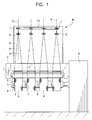
- FIG. 1 is a side view showing a schematic configuration of a yarn winder M according to an embodiment of the present invention.
- a plurality of bobbins B are set on one bobbin holder H so that a plurality of yarn packages P can be formed at the same time.
- four bobbins B are set on the bobbin holder H, however, the number of bobbins set on the bobbin holder H can be six, eight, twelve, etc..
- a machine body K of the yarn winder M is provided with the bobbin holder H for holding a plurality of bobbins B, and an elevating unit U including a traverse device T and a contact roller C.
- the elevating unit U can elevate and descend in relation to the machine body K.
- the yarn winder M is set such that accompanying the increase in the winding diameter of the package P that is formed by the yarn being wound on the bobbin B, the contact roller C elevates to maintain the contact pressure suitable.
- the contact roller C is cylinder shaped, arranged in parallel to the bobbin holder H, and is supported rotatable to a casing of the elevating unit U.
- the bobbin holder H is cylinder shaped, supported in a cantilever to the machine body K, and is made rotatable and driven by a motor (not shown in the drawings).
- two bobbin holders H are provided in 180 degrees interval on a turret plate that is attached rotatable to the machine body K, and one of the bobbin holders H is provided at a winding position, and the other bobbin holder H is provided at a standby position.
- the turret plate and the bobbin holder H at the standby position are abbreviated.
- the elevating unit U includes the traverse device T and the contact roller C.
- a rotary blade traverse device, a cam traverse device, or the like are adopted for the traverse device T.
- the traverse device T is provided with a traverse guide 12 for guiding a yarn S in a traverse direction.
- a traverse fulcrum guide 1 and a tension detector 3 are provided in this order.
- the traverse fulcrum guide 1 and the tension detector 3 are attached to a support member 9 that is joined to a casing of the elevating unit U.
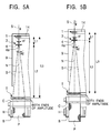
- the traverse fulcrum guide 1, the tension detector 3 and the traverse device T are joined to the elevating unit U so that to form one body, and as shown in Figure 5A that shows a case in which the diameter of the yarn package P is small, and as shown in Figure 5B that shows a case in which the diameter of the yarn package P is large, each of distances during winding process, a distance L1 from the traverse fulcrum guide 1 to the tension detector 3, a distance L2 from the tension detector 3 to the traverse device T, and a distance L3 from the traverse fulcrum guide 1 to the traverse device T, are set to be constant regardless of the winding diameter of the yarn package P.
- the traverse fulcrum guide 1 that is provided to the upstream side of the yarn running direction in relation to the traverse device T determines a standard position when traversing the yarn S from side to side by the traverse device T.
- the standard position at the winding process is set on approximately a bisector N of the traverse width of the traverse device T.
- the traverse fulcrum guide 1 is guided by a guide member 14 that is attached to the support member 9.
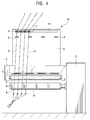
- the traverse fulcrum guide 1 is made transferable along the axis direction of the bobbin holder H toward a tip end (free end) of the bobbin holder H, from the standard position shown in Figure 1 to an initial stage threading work position shown in Figure 4.
- the traverse fulcrum guide 1 is, as shown in an enlarged view in Figure 3, formed with a ring-shaped guide section 1a where the yarn S passes through, and a base 1c that supports the guide section 1a.
- a notch 1b is formed so that the yarn S can be inserted to the ring section 1a easily.
- the tension detector 3 is provided between the traverse fulcrum guide 1 and the traverse device T, and detects the tension of the yarn S that passes through the traverse fulcrum guide 1 and that is traversed by the traverse device T.
- the tension detector 3 is fixed on the support member 9, and is provided on approximately the bisector N of the traverse width of each corresponding traverse device T and directly below the standard position of the traverse fulcrum guide 1 in the winding process.
- the tension detector 3 includes a contact element 4 that holds the yarn S at the tension detecting position, a shaft 5 that is interlocked to the contact element 4, a pressure-sensitive sensor 6 that is attached to both the left and the right sides of the shaft 5 in proximity to a base 7, and the base 7 that supports the shaft 5.
- a storing section 4a for the yarn S is formed on the contact element 4, by notching appropriate length from the center tip of the contact element 4 in the axis direction of the shaft 5.
- insert guide sections 4b that have slanting edges are provided to the left and right edges of the contact element 4 so as to sandwich the storing section 4a.
- the storing section 4a is a section for holding the yarn S at the tension detecting position.
- the insert guide sections 4b guides the yarn S into the storing section 4a, which is the tension detecting position, by a traverse movement of the yarn S at time of the initial stage threading.
- the tension detector 3 measures the tension of the yarn S during the winding process in the following way.
- the contact element 4 and the shaft 5 of the tension detector 3 are preferable to be light weighted as much as possible.
- the left and right edges of tip of the contact element 4 are preferably to be tapered off by the insert guide sections 4b that have slanting edges.
- the insert guide sections 4b are also contributing to reducing the weight of the contact element 4 by narrowing the width of the contact element 4 toward the tip end.
- the yarn winder M of the present embodiment is provided with the traverse fulcrum guide 1, the tension detector 3 and the traverse device T for each bobbin B.
- the elevating unit U elevates to maintain the contact pressure of the contact roller C against the yarn package P to be suitable. Since the traverse device T, the traverse fulcrum guide 1 and the tension detector 3 elevate as one body with the elevating unit U that is elevating, as shown in Figures 5A and 5B, each of the distance L1 from the traverse fulcrum guide 1 to the tension detector 3, the distance L2 from the tension detector 3 to the traverse device T, and the distance L3 from the traverse fulcrum guide 1 to the traverse device T is also maintained at a constant value respectively.
- the angle ⁇ 1 is an algle between the traverse fulcrum guide 1 and the tension detector 3 that the yarn S is slanting in relation to the bisector N or the traverse width of the traverse device T.
- the angle ⁇ 2 is an angle between the tension detector 3 and the traverse device T that the yarn S is slanting in relation to the bisector N.
- the present invention wherein each of the distance between the traverse device T and the traverse fulcrum guide 1, between the traverse fulcrum guide 1 and the tension detector 3, and between the traverse device T and the tension detector 3 are maintained constant during the winding process, can be applied to the yarn winder M, which the elevating unit U is elevated along with the contact roller C accompanying the increase in the winding diameter of the yarn package.
- the present invention can be applied to a yarn winder, which maintains the contact pressure of the yarn package P against the contact roller C to be suitable by descending the bobbin holder H in the direction of an arrow D, accompanying the increase in the winding diameter of the yarn package P.
- the condition of when detecting the yarn tension by contacting the yarn that is traversed like a swing of a pendulum against the tension detector at both ends of the amplitude of the yarn during the winding process is maintained constant, and an accurate tension value can be obtained regardless of the winding diameter of the package.
- high quality yarn packages, which the tension is controlled at a target value can be obtained.
- the contact pressure of the contact roller against the yarn package is maintained suitable by elevating the elevating unit, accompanying the increase in the winding diameter of the yarn package, it is especially preferable to apply the second aspect of the present invention.
- the relationship of each of the distances, the distance between the traverse device and the traverse fulcrum guide, the distance between the traverse fulcrum guide and the tension detector, and the distance between the traverse device and the tension detector can be maintained constant easily during the winding process.
Landscapes
- Winding Filamentary Materials (AREA)
- Tension Adjustment In Filamentary Materials (AREA)
- Yarns And Mechanical Finishing Of Yarns Or Ropes (AREA)
- Filamentary Materials, Packages, And Safety Devices Therefor (AREA)
Abstract
Description
- The present invention relates to a yarn winder for continuously winding a filament yarn such as synthetic fiber, which comprises a tension detector for monitoring yarn tension during winding.
- For winding control methods in the yarn winder for winding the filament yarn of synthetic fiber that is melt-spun continuously from a spinning machine, to a bobbin while traversing the filament yarn by a traverse device, two kinds of methods are mainly known, a yarn speed control with yarn speed as control target, and a yarn tension control with yarn tension as target.
- The yarn speed control method had problems that when the traverse speed is changed during winding, the yarn tension also changed, and it was difficult to control this change in the yarn tension.
- On the other hand, the yarn tension control method can form satisfying yarn packages, without any bulge or saddle. Therefore, the yarn tension control method is considered as an extremely effective technology in carrying out winding process that changes the traverse speed during winding.
- In the case the yarn tension control method is adopted, it is necessary to provide the tension detector for detecting the tension of the yarn by contacting against such yarn. However, having the tension detector to contact against the yarn that is running at a high speed generally causes the yarn quality to deteriorate. Therefore, to reduce bad influence on the yarn as much as possible, there is a method proposed conventionally for the detection of the yarn tension. Such method is to provide the tension detector directly below a traverse fulcrum, where the tension detector includes a contact member that contacts minutely against both ends of the amplitude of the yarn that is traversed like a swing of a pendulum (for example, Japanese Patent Publication No. 51-44668, and Japanese Patent Publication No. 60-47985).
- In the yarn winder adapting the yarn tension control method, the traverse fulcrum guide and the tension detector can be attached to a fixed frame, and the traverse device and a contact roller can be provided within an elevating unit. When forming a yarn package by winding the yarn, which passes through the traverse fulcrum guide and the tension detector and which is traversed by the traverse device, while contacting the yarn against the contact roller, the elevating unit comprising the contact roller can be elevated accompanying the increase in the winding diameter of the yarn package. As a result, the contact pressure against the yarn package is maintained suitable. However, accompanying the approach of the traverse device to a fixed traverse fulcrum guide by the elevating unit that is elevating, the traverse angle of the yarn that is traversed like a swing of a pendulum increases, and the yarn presses hard against the contact member of the tension detector at both ends of the amplitude. As a result, there is a problem in that an accurate tension value cannot be obtained.
- The object of the present invention is to provide a means for obtaining accurate tension value, especially in a yarn winder that adopts the above-mentioned tension detecting method. According to a first aspect of the present invention, a yarn winder comprises a bobbin holder that is set with at least a bobbin for winding at least a yarn, a contact roller that rotates while contacting against at least a yarn package, a traverse device that is provided to an upstream side of the contact roller and traverses the yarn that is being fed, a traverse fulcrum guide that is to be a traverse fulcrum of the yarn that is traversed in the upstream side of the traverse device, and a tension detector that is located between the traverse device and the traverse fulcrum guide and that detects a tension of the yarn by contacting against a contact element, the yarn that is located at both ends of the traverse amplitude. In addition, during winding process, each of the distance between the traverse fulcrum guide and the tension detector, the distance between the tension detector and the traverse device, and the distance between the traverse fulcrum guide and the traverse device, is set constant regardless of a winding diameter of the yarn package. According to the present invention, since each of the afore-mentioned distances are set constant respectively, by maintaining the condition to be constant when the yarn that runs while traversing like a swing of a pendulum is contacted against the tension detector at both ends of the amplitude to measure the yarn tension, an accurate tension value can be obtained.
- According to a second aspect of the present invention, the present invention is preferable to be applied to the yarn winder in which a traverse fulcrum guide and a tension detector are attached to an elevating unit that includes the traverse device and that elevates accompanying an increase in a winding diameter of a yarn package.
- According to a third aspect of the present invention, the present invention can be applied to the yarn winder wherein the bobbin holder descends accompanying the increase in the winding diameter of a yarn package, and a contact pressure of the yarn package against the contact roller is maintained suitable.
-
- Figure 1 is a side view showing schematic configuration of a yarn winder according to an embodiment of the present invention.
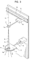
- Figure 2 is a front view showing principal components of the yarn winder of Figure 1.
- Figure 3 is a perspective view showing a traverse fulcrum guide and a tension detector of the yarn winder of Figure 1.
- Figure 4 is a side view showing the yarn winder of Figure 1, under a condition in which threading work is started.
- Figures 5A and 5B are side views showing principal components corresponding to one bobbin of the yarn winder of Figure 1 during a regular yarn winding process. Figure 5A shows a state in which the diameter of a yarn package is small. Figure 5B shows a state in which the diameter of the yarn package is large.
- Figure 6 is a front view showing principal components of the yarn winder, according to another embodiment of the present invention.
-
- An embodiment of the present invention will be described where the present invention is applied to a yarn winder that forms a yarn package by winding while traversing by a traverse device, a filament yarn of synthetic fiber that is melt-spun continuously from a spinning machine.
- Figure 1 is a side view showing a schematic configuration of a yarn winder M according to an embodiment of the present invention. A plurality of bobbins B are set on one bobbin holder H so that a plurality of yarn packages P can be formed at the same time. In the drawing, four bobbins B are set on the bobbin holder H, however, the number of bobbins set on the bobbin holder H can be six, eight, twelve, etc.. A machine body K of the yarn winder M is provided with the bobbin holder H for holding a plurality of bobbins B, and an elevating unit U including a traverse device T and a contact roller C. The elevating unit U can elevate and descend in relation to the machine body K. The yarn winder M is set such that accompanying the increase in the winding diameter of the package P that is formed by the yarn being wound on the bobbin B, the contact roller C elevates to maintain the contact pressure suitable.
- The contact roller C is cylinder shaped, arranged in parallel to the bobbin holder H, and is supported rotatable to a casing of the elevating unit U. The bobbin holder H is cylinder shaped, supported in a cantilever to the machine body K, and is made rotatable and driven by a motor (not shown in the drawings). Generally, in the yarn winder M, two bobbin holders H are provided in 180 degrees interval on a turret plate that is attached rotatable to the machine body K, and one of the bobbin holders H is provided at a winding position, and the other bobbin holder H is provided at a standby position. In the yarn winder M shown in Figure 1, the turret plate and the bobbin holder H at the standby position are abbreviated.
- As shown in Figure 2, the elevating unit U includes the traverse device T and the contact roller C. A rotary blade traverse device, a cam traverse device, or the like are adopted for the traverse device T. The traverse device T is provided with a
traverse guide 12 for guiding a yarn S in a traverse direction. - Above the elevating unit U, from the upstream side of the yarn path toward the downstream side, a
traverse fulcrum guide 1, and atension detector 3 are provided in this order. Thetraverse fulcrum guide 1 and thetension detector 3 are attached to asupport member 9 that is joined to a casing of the elevating unit U. As a result, the distance between thetraverse fulcrum guide 1 and thetension detector 3 during a winding process (when the yarn S is wound around the bobbin B) is set to be constant regardless of the winding diameter of the yarn package P. In other words, thetraverse fulcrum guide 1, thetension detector 3 and the traverse device T are joined to the elevating unit U so that to form one body, and as shown in Figure 5A that shows a case in which the diameter of the yarn package P is small, and as shown in Figure 5B that shows a case in which the diameter of the yarn package P is large, each of distances during winding process, a distance L1 from thetraverse fulcrum guide 1 to thetension detector 3, a distance L2 from thetension detector 3 to the traverse device T, and a distance L3 from thetraverse fulcrum guide 1 to the traverse device T, are set to be constant regardless of the winding diameter of the yarn package P. - The
traverse fulcrum guide 1 that is provided to the upstream side of the yarn running direction in relation to the traverse device T determines a standard position when traversing the yarn S from side to side by the traverse device T. The standard position at the winding process is set on approximately a bisector N of the traverse width of the traverse device T. In addition, thetraverse fulcrum guide 1 is guided by aguide member 14 that is attached to thesupport member 9. Thetraverse fulcrum guide 1 is made transferable along the axis direction of the bobbin holder H toward a tip end (free end) of the bobbin holder H, from the standard position shown in Figure 1 to an initial stage threading work position shown in Figure 4. Thetraverse fulcrum guide 1 is, as shown in an enlarged view in Figure 3, formed with a ring-shaped guide section 1a where the yarn S passes through, and abase 1c that supports theguide section 1a. In addition, at an appropriate part of theguide section 1a, anotch 1b is formed so that the yarn S can be inserted to thering section 1a easily. - As shown in Figure 1, the
tension detector 3 is provided between thetraverse fulcrum guide 1 and the traverse device T, and detects the tension of the yarn S that passes through thetraverse fulcrum guide 1 and that is traversed by the traverse device T. For connecting cable for transmitting tension detecting signal to controllers provided appropriately, thetension detector 3 is fixed on thesupport member 9, and is provided on approximately the bisector N of the traverse width of each corresponding traverse device T and directly below the standard position of thetraverse fulcrum guide 1 in the winding process. As shown in Figure 3, thetension detector 3 includes acontact element 4 that holds the yarn S at the tension detecting position, ashaft 5 that is interlocked to thecontact element 4, a pressure-sensitive sensor 6 that is attached to both the left and the right sides of theshaft 5 in proximity to abase 7, and thebase 7 that supports theshaft 5. Astoring section 4a for the yarn S is formed on thecontact element 4, by notching appropriate length from the center tip of thecontact element 4 in the axis direction of theshaft 5. In addition, insertguide sections 4b that have slanting edges are provided to the left and right edges of thecontact element 4 so as to sandwich thestoring section 4a. The storingsection 4a is a section for holding the yarn S at the tension detecting position. Theinsert guide sections 4b guides the yarn S into thestoring section 4a, which is the tension detecting position, by a traverse movement of the yarn S at time of the initial stage threading. - The
tension detector 3 measures the tension of the yarn S during the winding process in the following way. - As shown in Figure 3, when the yarn S, which passes through the
traverse fulcrum guide 1, is inserted through thestoring section 4a of thecontact element 4 and the winding is carried out, the yarn S is traversed from side to side by the traverse device T, as shown with chained double-dashed line in Figure 3. As a result, since the yarn S is pressurized against the left and right inner edges of thestoring section 4a, theshaft 5 transforms so as to vibrate to the traverse direction via thecontact element 4. The pressure-sensitive sensor 6 that is attached to theshaft 5 detects the size of a force applied to theshaft 5 when the yarn S contacts against thecontact element 4, and calculates the tension of the yarn S in accordance with the detected size. The tension detecting method adopted in the present embodiment can minimize the influence to be applied on the yarn S, because the time when thetension detector 3 and the yarn S are contacting against one another is extremely short, and the bent of the yarn S during the contact with thetension detector 3 is extremely small. - Further, for a subtle detection of the tension, the
contact element 4 and theshaft 5 of thetension detector 3 are preferable to be light weighted as much as possible. In this regard, the left and right edges of tip of thecontact element 4 are preferably to be tapered off by theinsert guide sections 4b that have slanting edges. In other words, theinsert guide sections 4b are also contributing to reducing the weight of thecontact element 4 by narrowing the width of thecontact element 4 toward the tip end. - For winding each of the yarns S to each of a plurality of bobbins B that are set on one bobbin holder H at the same time, the yarn winder M of the present embodiment is provided with the
traverse fulcrum guide 1, thetension detector 3 and the traverse device T for each bobbin B. - Accompanying the increase in the winding diameter of the yarn package P, the elevating unit U elevates to maintain the contact pressure of the contact roller C against the yarn package P to be suitable. Since the traverse device T, the
traverse fulcrum guide 1 and thetension detector 3 elevate as one body with the elevating unit U that is elevating, as shown in Figures 5A and 5B, each of the distance L1 from thetraverse fulcrum guide 1 to thetension detector 3, the distance L2 from thetension detector 3 to the traverse device T, and the distance L3 from thetraverse fulcrum guide 1 to the traverse device T is also maintained at a constant value respectively. Accordingly, when measuring the tension of the yarn S by pressurizing thecontact element 4 of thetension detector 3 against the yarn S at both ends of the amplitude of the yarn S that is traversed like a swing of pendulum while running, an agle 1 and an agle 2 are maintained at constant value. As a result, a precise tension value can be obtained. Further, the angle 1 is an algle between thetraverse fulcrum guide 1 and thetension detector 3 that the yarn S is slanting in relation to the bisector N or the traverse width of the traverse device T. The angle 2 is an angle between thetension detector 3 and the traverse device T that the yarn S is slanting in relation to the bisector N. - Further, the present invention wherein each of the distance between the traverse device T and the
traverse fulcrum guide 1, between thetraverse fulcrum guide 1 and thetension detector 3, and between the traverse device T and thetension detector 3 are maintained constant during the winding process, can be applied to the yarn winder M, which the elevating unit U is elevated along with the contact roller C accompanying the increase in the winding diameter of the yarn package. In addition, as shown in Figure 6, the present invention can be applied to a yarn winder, which maintains the contact pressure of the yarn package P against the contact roller C to be suitable by descending the bobbin holder H in the direction of an arrow D, accompanying the increase in the winding diameter of the yarn package P. - According to the first aspect of the present invention, the condition of when detecting the yarn tension by contacting the yarn that is traversed like a swing of a pendulum against the tension detector at both ends of the amplitude of the yarn during the winding process, is maintained constant, and an accurate tension value can be obtained regardless of the winding diameter of the package. As a result, high quality yarn packages, which the tension is controlled at a target value, can be obtained.
- In the case the contact pressure of the contact roller against the yarn package is maintained suitable by elevating the elevating unit, accompanying the increase in the winding diameter of the yarn package, it is especially preferable to apply the second aspect of the present invention. As a result, the relationship of each of the distances, the distance between the traverse device and the traverse fulcrum guide, the distance between the traverse fulcrum guide and the tension detector, and the distance between the traverse device and the tension detector, can be maintained constant easily during the winding process.
- According to the third aspect of the present invention, even in the case the contact pressure of the yarn package against the contact roller is maintained suitable by descending the bobbin holder accompanying the progress in the winding of the yarn, accurate tension value of the yarn can be obtained regardless of the winding diameter of the yarn package. As a result, high quality yarn packages, which the yarn tension is controlled at a targeted value, can be obtained.
Claims (3)
- A yarn winder comprising:wherein each of distances during the winding process, between the traverse fulcrum guide and the tension detector, between the tension detector and the traverse device, and between the traverse fulcrum guide and the traverse device, is maintained constant regardless of a winding diameter of the yarn package.a bobbin holder that is set with at least a bobbin for winding at least a yarn;a contact roller that rotates while contacting against at least a yarn package;a traverse device that is provided to an upstream side of the contact roller and traverses the yarn;a traverse fulcrum guide which is to be a traverse fulcrum of the yarn that is traversed in the upstream of the traverse device; anda tension detector that is located between the traverse device and the traverse fulcrum guide, and that detects a tension of the yarn by contacting the yarn located at both ends of an amplitude of traversing yarn against a contact element;
- A yarn winder according to claim 1, wherein the traverse fulcrum guide and the tension detector are attached to an elevating unit, which includes the traverse device and which elevates accompanying an increase in the winding diameter of the yarn package.
- A yarn winder according to claim 1, wherein the bobbin holder descends accompanying the increase in the winding diameter of the yarn package for a contact pressure of the yarn package against the contact roller to be maintained suitable.
Applications Claiming Priority (2)
| Application Number | Priority Date | Filing Date | Title |
|---|---|---|---|
| JP2001306027A JP3724402B2 (en) | 2001-10-02 | 2001-10-02 | Yarn winding machine |
| JP2001306027 | 2001-10-02 |
Publications (2)
| Publication Number | Publication Date |
|---|---|
| EP1300357A1 true EP1300357A1 (en) | 2003-04-09 |
| EP1300357B1 EP1300357B1 (en) | 2006-03-15 |
Family
ID=19125731
Family Applications (1)
| Application Number | Title | Priority Date | Filing Date |
|---|---|---|---|
| EP02021475A Expired - Lifetime EP1300357B1 (en) | 2001-10-02 | 2002-09-25 | Yarn winder |
Country Status (4)
| Country | Link |
|---|---|
| EP (1) | EP1300357B1 (en) |
| JP (1) | JP3724402B2 (en) |
| CN (1) | CN1270955C (en) |
| DE (1) | DE60209843T2 (en) |
Cited By (1)
| Publication number | Priority date | Publication date | Assignee | Title |
|---|---|---|---|---|
| CN116330690A (en) * | 2023-04-03 | 2023-06-27 | 洛阳双瑞橡塑科技有限公司 | Tooling and method for preparing peelable variable-diameter module |
Families Citing this family (2)
| Publication number | Priority date | Publication date | Assignee | Title |
|---|---|---|---|---|
| EP2479129B1 (en) * | 2011-01-25 | 2016-08-10 | Murata Machinery, Ltd. | Yarn winding machine |
| JP6935243B2 (en) * | 2017-06-21 | 2021-09-15 | Tmtマシナリー株式会社 | Thread winder |
Citations (10)
| Publication number | Priority date | Publication date | Assignee | Title |
|---|---|---|---|---|
| JPS4848171A (en) * | 1971-10-20 | 1973-07-07 | ||
| US3931938A (en) * | 1974-03-18 | 1976-01-13 | Toray Industries, Inc. | Method and apparatus for winding yarn into yarn package |
| US4245794A (en) * | 1978-02-16 | 1981-01-20 | Toray Industries, Inc. | Yarn winding apparatus |
| US4394986A (en) * | 1981-05-13 | 1983-07-26 | Toray Industries, Inc. | Yarn winding apparatus |
| JPS5990229A (en) * | 1982-11-16 | 1984-05-24 | Anritsu Corp | Positioning mechanism for magnetic head |
| US5029762A (en) * | 1988-12-22 | 1991-07-09 | Barmag A.G. | Yarn winding apparatus and method |
| US5074481A (en) * | 1989-05-25 | 1991-12-24 | W. Schlafhorst Ag & Co. | Method and apparatus for monitoring the yarn winding production process |
| JPH08324889A (en) * | 1995-06-05 | 1996-12-10 | Toray Ind Inc | Thread switching method for turret type yarn winding machine, turret type yarn winding machine and bobbin for winding yarn |
| JPH10273268A (en) * | 1997-03-28 | 1998-10-13 | Toray Ind Inc | How to switch yarns in the turret yarn winding machine |
| DE19938491A1 (en) * | 1999-08-13 | 2001-02-15 | Schlafhorst & Co W | Winding station for cross wound bobbins has a monitor system to give the actual draw force on the yarn using two time spans with and without limit stop sensors and a given threshold value for computation |
-
2001
- 2001-10-02 JP JP2001306027A patent/JP3724402B2/en not_active Expired - Lifetime
-
2002
- 2002-09-25 EP EP02021475A patent/EP1300357B1/en not_active Expired - Lifetime
- 2002-09-25 DE DE60209843T patent/DE60209843T2/en not_active Expired - Lifetime
- 2002-09-29 CN CN02143970.2A patent/CN1270955C/en not_active Expired - Lifetime
Patent Citations (10)
| Publication number | Priority date | Publication date | Assignee | Title |
|---|---|---|---|---|
| JPS4848171A (en) * | 1971-10-20 | 1973-07-07 | ||
| US3931938A (en) * | 1974-03-18 | 1976-01-13 | Toray Industries, Inc. | Method and apparatus for winding yarn into yarn package |
| US4245794A (en) * | 1978-02-16 | 1981-01-20 | Toray Industries, Inc. | Yarn winding apparatus |
| US4394986A (en) * | 1981-05-13 | 1983-07-26 | Toray Industries, Inc. | Yarn winding apparatus |
| JPS5990229A (en) * | 1982-11-16 | 1984-05-24 | Anritsu Corp | Positioning mechanism for magnetic head |
| US5029762A (en) * | 1988-12-22 | 1991-07-09 | Barmag A.G. | Yarn winding apparatus and method |
| US5074481A (en) * | 1989-05-25 | 1991-12-24 | W. Schlafhorst Ag & Co. | Method and apparatus for monitoring the yarn winding production process |
| JPH08324889A (en) * | 1995-06-05 | 1996-12-10 | Toray Ind Inc | Thread switching method for turret type yarn winding machine, turret type yarn winding machine and bobbin for winding yarn |
| JPH10273268A (en) * | 1997-03-28 | 1998-10-13 | Toray Ind Inc | How to switch yarns in the turret yarn winding machine |
| DE19938491A1 (en) * | 1999-08-13 | 2001-02-15 | Schlafhorst & Co W | Winding station for cross wound bobbins has a monitor system to give the actual draw force on the yarn using two time spans with and without limit stop sensors and a given threshold value for computation |
Non-Patent Citations (3)
| Title |
|---|
| PATENT ABSTRACTS OF JAPAN vol. 008, no. 204 (P - 301) 18 September 1984 (1984-09-18) * |
| PATENT ABSTRACTS OF JAPAN vol. 1997, no. 04 30 April 1997 (1997-04-30) * |
| PATENT ABSTRACTS OF JAPAN vol. 1999, no. 01 29 January 1999 (1999-01-29) * |
Cited By (1)
| Publication number | Priority date | Publication date | Assignee | Title |
|---|---|---|---|---|
| CN116330690A (en) * | 2023-04-03 | 2023-06-27 | 洛阳双瑞橡塑科技有限公司 | Tooling and method for preparing peelable variable-diameter module |
Also Published As
| Publication number | Publication date |
|---|---|
| CN1270955C (en) | 2006-08-23 |
| JP2003113544A (en) | 2003-04-18 |
| DE60209843D1 (en) | 2006-05-11 |
| DE60209843T2 (en) | 2006-11-30 |
| CN1408630A (en) | 2003-04-09 |
| EP1300357B1 (en) | 2006-03-15 |
| JP3724402B2 (en) | 2005-12-07 |
Similar Documents
| Publication | Publication Date | Title |
|---|---|---|
| US6145775A (en) | Yarn winding apparatus and method | |
| JP4178034B2 (en) | Untreated spinning fiber unwinding machine | |
| US6189826B1 (en) | Apparatus and method for guiding and cutting a continuously advancing yarn during a winding process | |
| CN220578615U (en) | Yarn winding unit | |
| JPH028151A (en) | Method and device for rolling conical cheese rolls | |
| JPH10115565A (en) | Apparatus for measuring thread tension of running thread | |
| JP2002145527A (en) | Winder for particularly sensitive winding materials | |
| EP1300357B1 (en) | Yarn winder | |
| US6533211B2 (en) | Method of operating a textile machine for producing cheeses | |
| GB2137239A (en) | Coiling systems | |
| US4060207A (en) | Yarn winding mechanism in spinning machine | |
| JP4395828B2 (en) | Yarn winder with tension detector | |
| US6315236B1 (en) | Apparatus and method for guiding and cutting an advancing yarn during a package doff | |
| US4076181A (en) | Precision winder for drawing and packaging synthetic fibers | |
| US5285975A (en) | Process and device to spool a yarn on a spinning machine/spooling device | |
| US4495758A (en) | Apparatus and method for forming a wrapped yarn | |
| EP0156452A1 (en) | Textile yarn spinning machine with supply strand interruption | |
| CN111132918A (en) | Yarn Coiler | |
| JP7513657B2 (en) | Yarn winding device | |
| US4677387A (en) | Package quality monitor | |
| JP3213768B2 (en) | Wire rod winding method and device | |
| SU1414744A1 (en) | Device for winding filamentary material onto package | |
| US4672801A (en) | Apparatus for producing two-component thread | |
| NL1013452C2 (en) | Method and device for reducing or preventing damage to a fiber. | |
| CA2018004C (en) | Detection apparatus for paper build up on reel bar |
Legal Events
| Date | Code | Title | Description |
|---|---|---|---|
| PUAI | Public reference made under article 153(3) epc to a published international application that has entered the european phase |
Free format text: ORIGINAL CODE: 0009012 |
|
| AK | Designated contracting states |
Kind code of ref document: A1 Designated state(s): AT BE BG CH CY CZ DE DK EE ES FI FR GB GR IE IT LI LU MC NL PT SE SK TR Designated state(s): AT BE BG CH CY CZ DE DK EE ES FI FR GB GR IE IT LI LU MC NL PT SE SK TR |
|
| AX | Request for extension of the european patent |
Extension state: AL LT LV MK RO SI |
|
| 17P | Request for examination filed |
Effective date: 20030807 |
|
| AKX | Designation fees paid |
Designated state(s): CH DE LI |
|
| 17Q | First examination report despatched |
Effective date: 20040702 |
|
| GRAP | Despatch of communication of intention to grant a patent |
Free format text: ORIGINAL CODE: EPIDOSNIGR1 |
|
| GRAS | Grant fee paid |
Free format text: ORIGINAL CODE: EPIDOSNIGR3 |
|
| GRAA | (expected) grant |
Free format text: ORIGINAL CODE: 0009210 |
|
| AK | Designated contracting states |
Kind code of ref document: B1 Designated state(s): CH DE LI |
|
| REG | Reference to a national code |
Ref country code: CH Ref legal event code: EP |
|
| REF | Corresponds to: |
Ref document number: 60209843 Country of ref document: DE Date of ref document: 20060511 Kind code of ref document: P |
|
| REG | Reference to a national code |
Ref country code: CH Ref legal event code: NV Representative=s name: E. BLUM & CO. PATENTANWAELTE |
|
| PLBE | No opposition filed within time limit |
Free format text: ORIGINAL CODE: 0009261 |
|
| STAA | Information on the status of an ep patent application or granted ep patent |
Free format text: STATUS: NO OPPOSITION FILED WITHIN TIME LIMIT |
|
| 26N | No opposition filed |
Effective date: 20061218 |
|
| REG | Reference to a national code |
Ref country code: CH Ref legal event code: PFA Owner name: MURATA KIKAI KABUSHIKI KAISHA Free format text: MURATA KIKAI KABUSHIKI KAISHA#3 MINAMI, OCHIAI-CHO, KISSHOIN#MINAMI-KU KYOTO-SHI KYOTO 601 (JP) -TRANSFER TO- MURATA KIKAI KABUSHIKI KAISHA#3 MINAMI, OCHIAI-CHO, KISSHOIN#MINAMI-KU KYOTO-SHI KYOTO 601 (JP) |
|
| REG | Reference to a national code |
Ref country code: DE Ref legal event code: R082 Ref document number: 60209843 Country of ref document: DE Representative=s name: PATENTANWAELTE WEICKMANN & WEICKMANN, DE Ref country code: DE Ref legal event code: R082 Ref document number: 60209843 Country of ref document: DE Representative=s name: WEICKMANN & WEICKMANN PATENTANWAELTE - RECHTSA, DE Ref country code: DE Ref legal event code: R082 Ref document number: 60209843 Country of ref document: DE Representative=s name: WEICKMANN & WEICKMANN PATENT- UND RECHTSANWAEL, DE |
|
| PGFP | Annual fee paid to national office [announced via postgrant information from national office to epo] |
Ref country code: CH Payment date: 20210920 Year of fee payment: 20 |
|
| PGFP | Annual fee paid to national office [announced via postgrant information from national office to epo] |
Ref country code: DE Payment date: 20210920 Year of fee payment: 20 |
|
| REG | Reference to a national code |
Ref country code: DE Ref legal event code: R071 Ref document number: 60209843 Country of ref document: DE |
|
| REG | Reference to a national code |
Ref country code: CH Ref legal event code: PL |