EP1299628B1 - Procede permettant de reguler la pression d'admission dans un moteur thermique dote d'un turbocompresseur a gaz d'echappement - Google Patents
Procede permettant de reguler la pression d'admission dans un moteur thermique dote d'un turbocompresseur a gaz d'echappement Download PDFInfo
- Publication number
- EP1299628B1 EP1299628B1 EP01951425A EP01951425A EP1299628B1 EP 1299628 B1 EP1299628 B1 EP 1299628B1 EP 01951425 A EP01951425 A EP 01951425A EP 01951425 A EP01951425 A EP 01951425A EP 1299628 B1 EP1299628 B1 EP 1299628B1
- Authority
- EP
- European Patent Office
- Prior art keywords
- turbine
- exhaust gas
- compressor
- determined
- pressure
- Prior art date
- Legal status (The legal status is an assumption and is not a legal conclusion. Google has not performed a legal analysis and makes no representation as to the accuracy of the status listed.)
- Expired - Lifetime
Links
Images


Classifications
-
- F—MECHANICAL ENGINEERING; LIGHTING; HEATING; WEAPONS; BLASTING
- F02—COMBUSTION ENGINES; HOT-GAS OR COMBUSTION-PRODUCT ENGINE PLANTS
- F02D—CONTROLLING COMBUSTION ENGINES
- F02D41/00—Electrical control of supply of combustible mixture or its constituents
- F02D41/0002—Controlling intake air
- F02D41/0007—Controlling intake air for control of turbo-charged or super-charged engines
-
- Y—GENERAL TAGGING OF NEW TECHNOLOGICAL DEVELOPMENTS; GENERAL TAGGING OF CROSS-SECTIONAL TECHNOLOGIES SPANNING OVER SEVERAL SECTIONS OF THE IPC; TECHNICAL SUBJECTS COVERED BY FORMER USPC CROSS-REFERENCE ART COLLECTIONS [XRACs] AND DIGESTS
- Y02—TECHNOLOGIES OR APPLICATIONS FOR MITIGATION OR ADAPTATION AGAINST CLIMATE CHANGE
- Y02T—CLIMATE CHANGE MITIGATION TECHNOLOGIES RELATED TO TRANSPORTATION
- Y02T10/00—Road transport of goods or passengers
- Y02T10/10—Internal combustion engine [ICE] based vehicles
- Y02T10/12—Improving ICE efficiencies
Definitions
- the invention relates to a method for regulating a boost pressure in an internal combustion engine with an exhaust gas turbocharger.
- An exhaust gas turbocharger (ATL) consists of two turbomachines: a turbine and a compressor, which are mounted on a common shaft.
- the turbine uses the energy contained in the exhaust gas to drive the compressor, which sucks fresh air and presses pre-compressed air into the cylinders of an internal combustion engine.
- the exhaust gas turbocharger is coupled by the air and exhaust gas mass flow fluidly with the internal combustion engine.
- Exhaust gas turbochargers are used in passenger car, truck and large combustion engines. In particular, in passenger car exhaust gas turbochargers, a regulation of the exhaust gas turbocharger is required because of the large speed range in order to achieve a nearly constant and accurate boost pressure in another speed range.
- boost pressure control and regulating devices are known. It must be considered that the charge pressure generated at the exhaust gas turbocharger usually depends on the operating point of the internal combustion engine.
- One option for influencing the boost pressure of an exhaust gas turbocharger is provided by turbochargers with variable turbine geometry (VTG).
- VTG controller variable turbine geometry
- WASTEGATE wastegate arranged on the exhaust side
- a method for controlling an internal combustion engine with a turbocharger and an exhaust gas recirculation is known in which by integrating the difference between the powers of the compressor and the turbine of the turbocharger, the speed of the supercharger shaft is determined. Based on the speed of the supercharger shaft, a boost pressure signal is then calculated. The boost pressure signal is then used together with other signals for controlling the internal combustion engine.
- the invention has for its object to provide a method for controlling the boost pressure, which allows simple means an accurate and reliable adjustment of the boost pressure.
- the power or the torque of the compressor is determined in a first step in the method.
- the power and torque of the compressor are linked by the turbocharger speed, where the torque is inversely proportional to the turbocharger speed and proportional to the power of the compressor.
- the power or torque losses occurring during the transmission from the turbine to the compressor are determined in a second step.
- gap losses, frictional losses of the shaft, etc. are taken into account.
- the proportionality factor depends on the operating condition and is determined by means of a characteristic curve.
- the power or the torque of the turbine is determined from the previously determined powers and torques.
- the power or torque of the compressor is determined using the isentropic compressor efficiency, wherein the isentropic compressor efficiency is determined by a first map depending on the pressure after the compressor and the fresh air mass flow and the ambient pressure and the ambient temperature.
- the isentropic compressor efficiency is stored as a first map depending on the pressure ratio between the pressure after the compressor and the ambient pressure and the quotient of fresh air mass flow and ambient pressure multiplied by the root from the ambient temperature.
- the value of the turbine speed is calculated by a second map depending on the mass flow through the compressor, the exhaust gas pressure after the compressor, ambient pressure and the exhaust gas temperature.
- the second map may additionally depend on the value of the control value for the boost pressure. It is also possible that the turbine speed is measured directly on the turbine. A contactless measurement of the turbine speed, such as, for example, an inductive or optical measurement, preferably takes place here.
- the power or torque loss is determined depending on the turbine speed over a predetermined characteristic.
- the losses in the characteristic curve not detected by the isentropic efficiency of the compressor are taken into account.
- the losses are shown as a function of the turbine speed.
- the characteristic is preferably not directly dependent on the turbine speed, but is normalized to the maximum turbine speed depending on the turbine speed.
- the manipulated variable is determined depending on the pressure ratio of the turbine, which is calculated via a polytropic relationship depending on the isentropic efficiency of the turbine, wherein the isentropic efficiency of the turbine using a third map depending on the mass flow through the turbine, the Exhaust temperature and the exhaust pressure in front of the turbine is determined.
- the value of the control value for the boost pressure is taken into account in the third map.
- the manipulated variable itself is determined via a fourth map depending on the exhaust gas mass flow, the exhaust pressure upstream of the turbine and the exhaust gas temperature, and the turbine pressure ratio, the turbine pressure ratio in turn depends on the calculated isentropic efficiency of the turbine.
- the fourth map depends on the turbine pressure ratio, which simplifies the use of already known and assembled turbine maps.
- the manipulated variable is determined by a map depending on the temperature ratio of the turbine, in which case the sizes of the exhaust gas mass flow, the exhaust pressure upstream of the turbine and the exhaust gas temperature are taken into account.
- the characteristic field is dependent on the temperature ratio at the turbine, whereby on the one hand a calculation of the isentropic efficiency of the turbine can be omitted, on the other hand, however, the fourth characteristic field must be set up temperature-dependent.
- the boost pressure is set via a turbine with a variable turbine geometry or via a WASTEGATE with a valve.
- the mass flow flowing through the WASTEGATE is formed as the difference between the exhaust mass flow and a maximum turbine mass flow to protect the turbine.
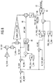
- the illustrated in Fig. 1 schematic structure of the control has an activation unit 10, which switch depending on the operating points of the internal combustion engine either in a controlled (closed-loop) or controlled (open-loop) operation.
- the activation conditions are dependent on the operating points of the internal combustion engine, which are determined either via a measurement or in the model of the air exhaust path 12.
- the setpoint unit 14 determines setpoint values which are dependent on the operating parameters of the internal combustion engine, the turbocharger, the ambient conditions and the calculated variables from the model 12. These setpoint values are additionally corrected dynamically in order to achieve an optimum adaptation of the setpoint value to unsteady operating states.
- the setpoints are forwarded to a pilot control unit 16 and to a controller 18.
- the pilot unit 16 may include a VTG model to drive the variable turbine geometry according to the predetermined setpoints.
- the controller can be designed as a conventional PI controller, which preferably has a parallel correction branch with DT 1 behavior. The controller compensates for inaccuracies of the pilot control and the model unit 12 for the air and exhaust path.
- a compressor model element 20 the power of the compressor is calculated from the thermodynamic conditions at the compressor.
- POW_CMP power of the compressor
- POW_TUR losses occurring at the shaft between the compressor and the turbine
- the sum of compressor power and power loss gives the turbine power (POW_TUR), which is applied as an input to the turbine model element 24.
- the turbine model element determines the duty cycle (BPAPWM) for variable turbine geometry (VTG) or WASTEGATE (WG). It will be apparent from the foregoing that the same view applies to the torques acting on the shaft.
- FIG. 3 shows the calculation of the compressor power (POW_CMP).
- the compressor power is the quotient of ambient pressure (AMP) 28 and pressure at the compressor (MAP) 26, the quotient 30 is applied to a characteristic KL 1 .
- the fresh air mass flow (MAF) 34 and the ambient temperature (TIA) 32 are also taken into account in the characteristic map KF 1 .
- the isentropic compressor efficiency (EFF_CMP) is determined. Taking into account the fresh air mass flow and the ambient temperature as well as the specific heat capacity of air can be calculated so the performance of the compressor. If the torque balance is to be considered instead of the power balance in FIG. 2, then the power of the compressor calculated in FIG. 3 is to be divided by the turbo speed (N_TCHA) and the factor 2 ⁇ .
- N_TCHA turbo speed
- T_UP_CMP 38 is also a Setpoint specification possible via the temperature ratio at the compressor.
- FIG. 4 illustrates that the compressor model explained with reference to FIG. 3 may also be used to derive the set point for the temperature from a desired value for the pressure at the compressor (MAP_SP) 40 and from a desired value for the fresh air mass flow (MAF_SP) after the compressor (T_UP_CMP_SP) 44 to calculate.
- MAP_SP pressure at the compressor
- MAF_SP fresh air mass flow
- T_UP_CMP_SP fresh air mass flow
- Fig. 5 shows the example of the power balance, the calculation of the power loss when no measurement of the turbine speed.
- the turbine speed (N_TCHA) 64 is determined using the map KF 2 depending on the pressure at the compressor (MAP) 56, the fresh air mass flow (MAF) 58, the ambient pressure (AMP) 60 and the ambient temperature (TIA) 62.
- MAP pressure at the compressor
- MAF fresh air mass flow
- AMP ambient pressure
- TIA ambient temperature
- N_TCHA_NOM the non-isentropic loss of the turbocharger
- Fig. 6 illustrates the calculation of the turbine torque in the event that the measured turbine speed (N_TCHA) 70 is known.
- the suitably normalized turbine speed can be used directly with the characteristic map KL 2 .
- An exemplary course for such a map is shown in the lower part of FIG. 6. It is shown that the non-isentropic losses of the turbocharger increase with the normalized turbine speed (N_TCHA / N_TCHA_NOM).
- FIG. 7 and 8 illustrate the calculation of the duty cycle (BPAPWM) 72 for the actuator. Both figures explain the calculation of the manipulated variable based on the turbine torque (TQ_TUR) 74. However, the same calculation can also be performed on the basis of the turbine power (POW_TUR) 74.
- the model shown in Fig. 7 allows a particularly simple switching for a WASTEGATE control.
- a control signal NC_WG
- NC_WG control signal
- a VTG control takes place in which the exhaust gas mass flow is used via the turbine (M_EXH) 76.
- M_WG mass flow over WASTEGATE 80
- M_TUR_MAX maximum mass flow across the turbine
- FIG. 8 shows the calculation of the manipulated variable 72 as a function of a characteristic map KF 4 84, which depends on the pressure ratio (DIV_PRS_TUR) 86 on the turbine.
- the pre-turbine exhaust pressure (PRS_EXH) and exhaust temperature (T_EXH) and mass flow over EGR values are estimated in the model of FIG. 8. It has been found that the sensitivity of the model to the manipulated variable 72 (BPAPWM), which on the one hand is the result of the model, on the other hand in the third characteristic field (KF 3 ) 88 is low, so that stable and accurate results are achieved.
- the manipulated variable 72 (duty cycle) on the third characteristic map it is also possible to use a position feedback of the wastegate or the VTG position on the characteristic map.
Claims (12)
- Procédé pour régler la pression de suralimentation dans un moteur à combustion interne comprenant un turbocompresseur à gaz d'échappement constitué d'une turbine et d'un compresseur d'air de suralimentation, procédé dans lequel une valeur de réglage pour ajuster la pression de suralimentation fournie par le compresseur d'air de suralimentation est déterminée, et qui comprend les étapes suivantes :- dans une première étape, la puissance ou le couple du compresseur (POW_CMP, TQ_CMP) est déterminé,- dans une deuxième étape, la perte de puissance ou de couple (POW_LOSS_TCHA, TQ_LOSS_TCHA) se produisant lors de la transmission depuis la turbine au compresseur, est déterminée, et,- dans une troisième étape, la puissance ou le couple de la turbine (POW_TUR, TQ_TUR) est déterminé à partir de la puissance ou du couple du compresseur et de la perte de puissance ou de couple, et une valeur de consigne de la valeur de réglage (BPAPWM) est établie.
- Procédé selon la revendication 1, caractérisé en ce que la puissance ou le couple du compresseur est déterminé en utilisant un rendement isentropique du compresseur (EFF_CMP),
le rendement isentropique du compresseur étant déterminé à l'aide d'un premier champ caractéristique KF1 en fonction des grandeurs suivantes :- la pression en aval du compresseur (MAP),- le débit massique d'air frais (MAF) amené au moteur à combustion interne,- la pression ambiante (AMP), et- la température ambiante (TIA). - Procédé selon la revendication 1 ou 2, caractérisé en ce que le nombre de tours de la turbine (N_TCHA) est calculé,
la valeur du nombre de tours de la turbine étant calculée à l'aide d'un deuxième champ caractéristique (KF2) en fonction des grandeurs suivantes :- le débit massique sur le compresseur (MAF),- la pression des gaz d'échappement en aval du compresseur, pression ambiante (AMP), et- la température ambiante (TIA). - Procédé selon la revendication 3, caractérisé en ce que le deuxième champ caractéristique (KF2) dépend en plus de la valeur de réglage (BPAPWH) de la pression de suralimentation.
- Procédé selon la revendication 1 ou 2, caractérisé en ce que le nombre de tours de la turbine (N_TCHA) est mesuré.
- Procédé selon l'une des revendications 3 à 5, caractérisé en ce que la perte de puissance ou de couple est déterminée en fonction du nombre de tours de la turbine (N_TCHA) à l'aide d'une ligne caractéristique prédéterminée.
- Procédé selon l'une des revendications 1 à 6, caractérisé en ce que la valeur de réglage (BPAPWH) de la pression de suralimentation est déterminée en fonction du rendement isentropique de la turbine, et que le rendement isentropique de la turbine (EFF_TUR) est déterminé à l'aide d'un troisième champ caractéristique KF3) en fonction des grandeurs suivantes :- le débit massique sur la turbine (M_TUR),- la température des gaz d'échappement (T_EXH), et- la pression des gaz d'échappement en amont de la turbine (PRS_EXH),- le troisième champ caractéristique (KF3) dépendant en plus du montant de la valeur de réglage (BPAPWH) de la pression de suralimentation.
- Procédé selon la revendication 7, caractérisé en ce que la valeur de réglage (BPAPWH) de la pression de suralimentation est calculée à l'aide d'un quatrième champ caractéristique (KF4) en fonction des grandeurs suivantes :- le débit massique des gaz d'échappement (M_EXH),- la pression des gaz d'échappement en amont de la turbine (PRS_EXH), et- la température des gaz d'échappement (T_EXH),ainsi que d'un rapport de pression de turbine (DIV_PRS_TUR) qui dépend du rendement isentropique déterminé de la turbine.
- Procédé selon l'une des revendications 1 à 6, caractérisé en ce que la valeur de réglage (BPAPWH) de la pression de suralimentation est déterminée à l'aide d'un champ caractéristique (KF4) en fonction du rapport de température sur la turbine (DIV_T_TUR) et des grandeurs suivantes :- le débit massique des gaz d'échappement (M_EXH),- la pression des gaz d'échappement en amont de la turbine (PRS_EXH), et- la température des gaz d'échappement (T_EXH).
- Procédé selon l'une des revendications 1 à 9, caractérisé en ce que la valeur de réglage (BPAPWH) de la pression de suralimentation agit sur une géométrie de turbine variable.
- Procédé selon l'une des revendications 1 à 9, caractérisé en ce que la valeur de réglage (BPAPWH) de la pression de suralimentation agit sur une soupape de pression de suralimentation (WASTEGATE) disposée du côté des gaz d'échappement.
- Procédé selon la revendication 11, caractérisé en ce que le débit massique sur la soupape de pression de suralimentation (M_WG) est formé par la différence entre le débit massique des gaz d'échappement (M_EXH) et un débit massique de turbine maximal (M_TUR_MAX).
Applications Claiming Priority (3)
| Application Number | Priority Date | Filing Date | Title |
|---|---|---|---|
| DE10033114 | 2000-07-07 | ||
| DE10033114 | 2000-07-07 | ||
| PCT/DE2001/002328 WO2002004799A1 (fr) | 2000-07-07 | 2001-06-25 | Procede permettant de reguler la pression d'admission dans un moteur thermique dote d'un turbocompresseur a gaz d'echappement |
Publications (2)
| Publication Number | Publication Date |
|---|---|
| EP1299628A1 EP1299628A1 (fr) | 2003-04-09 |
| EP1299628B1 true EP1299628B1 (fr) | 2006-08-02 |
Family
ID=7648168
Family Applications (1)
| Application Number | Title | Priority Date | Filing Date |
|---|---|---|---|
| EP01951425A Expired - Lifetime EP1299628B1 (fr) | 2000-07-07 | 2001-06-25 | Procede permettant de reguler la pression d'admission dans un moteur thermique dote d'un turbocompresseur a gaz d'echappement |
Country Status (4)
| Country | Link |
|---|---|
| US (1) | US6732523B2 (fr) |
| EP (1) | EP1299628B1 (fr) |
| DE (1) | DE50110631D1 (fr) |
| WO (1) | WO2002004799A1 (fr) |
Families Citing this family (36)
| Publication number | Priority date | Publication date | Assignee | Title |
|---|---|---|---|---|
| DE10145038A1 (de) * | 2001-09-13 | 2003-04-03 | Bosch Gmbh Robert | Verfahren und Vorrichtung zum Betreiben wenigstens eines Laders eines Verbrennungsmotors |
| US7058556B2 (en) | 2001-09-26 | 2006-06-06 | Goodrich Pump & Engine Control Systems, Inc. | Adaptive aero-thermodynamic engine model |
| DE10243268A1 (de) * | 2002-09-18 | 2004-03-25 | Robert Bosch Gmbh | Verfahren zum Regeln der Aufladung einer Brennkraftmaschine |
| DE10318243A1 (de) * | 2003-04-23 | 2004-11-11 | Robert Bosch Gmbh | Verfahren und Vorrichtung zum Betreiben einer Brennkraftmaschine |
| DE10319347A1 (de) * | 2003-04-30 | 2004-11-18 | Robert Bosch Gmbh | Verfahren und Vorrichtung zum Betreiben einer Brennkraftmaschine |
| DE10320977A1 (de) * | 2003-05-09 | 2004-12-09 | Siemens Ag | Verfahren zur Drehzahlüberwachung eines Bi-Turboladers |
| FR2858659B1 (fr) * | 2003-08-06 | 2006-03-17 | Peugeot Motocycles Sa | Systeme de controle du fonctionnement d'un moteur de vehicule a deux roues, de type scooter. |
| DE102004015742A1 (de) * | 2004-03-31 | 2005-10-27 | Robert Bosch Gmbh | Verfahren und Vorrichtung zum Betreiben einer Brennkraftmaschine |
| DE102004016010A1 (de) * | 2004-04-01 | 2005-10-20 | Bosch Gmbh Robert | Verfahren und Vorrichtung zum Betreiben einer Brennkraftmaschine |
| DE102004051837B4 (de) * | 2004-10-25 | 2006-11-09 | Siemens Ag | Verfahren und Vorrichtungen zum Steuern und zum Diagnostizieren eines Abgasturboladers |
| FR2882576B1 (fr) * | 2005-02-28 | 2007-05-25 | Renault Sas | Procede de regulation optimise en phase transitoire dans un turbocompresseur |
| DE102005054524A1 (de) * | 2005-11-14 | 2007-05-16 | Porsche Ag | Verfahren und Steuergerät zur Steuerung eines Turboladers mit steuerbarem Turbinen-Strömungsquerschnitt |
| US7668704B2 (en) * | 2006-01-27 | 2010-02-23 | Ricardo, Inc. | Apparatus and method for compressor and turbine performance simulation |
| JP4673818B2 (ja) * | 2006-10-26 | 2011-04-20 | トヨタ自動車株式会社 | ターボチャージャ付き内燃機関の制御装置 |
| FR2910055B1 (fr) * | 2006-12-15 | 2010-09-24 | Peugeot Citroen Automobiles Sa | Methode de determination d'une pression en entree d'une turbine de turbocompresseur equipant un moteur thermique |
| FR2910059A1 (fr) * | 2006-12-19 | 2008-06-20 | Renault Sas | Procede d'estimation de la pression des gaz d'echappement en amont d'une turbine de turbocompresseur |
| US7730724B2 (en) * | 2007-05-10 | 2010-06-08 | Ford Global Technologies, Llc | Turbocharger shaft over-speed compensation |
| FR2921114B1 (fr) * | 2007-09-13 | 2018-01-12 | Peugeot Citroen Automobiles Sa | Methode de determination d'une pression en entree d'une turbine de turbocompresseur equipant un moteur thermique |
| FR2921691B1 (fr) * | 2007-09-28 | 2012-08-17 | Inst Francais Du Petrole | Procede pour controler un turbocompresseur a l'aide d'un modele physique du regime du turbocompresseur |
| US7788922B2 (en) * | 2007-10-04 | 2010-09-07 | Delphi Technologies, Inc. | System and method for model based boost control of turbo-charged engines |
| US7748217B2 (en) * | 2007-10-04 | 2010-07-06 | Delphi Technologies, Inc. | System and method for modeling of turbo-charged engines and indirect measurement of turbine and waste-gate flow and turbine efficiency |
| FR2923538A3 (fr) * | 2007-11-12 | 2009-05-15 | Renault Sas | Systeme et procede d'estimation de la pression en amont d'une turbine de turbocompresseur et moteur thermique associ associe |
| DE102008054926B4 (de) * | 2007-12-19 | 2019-08-14 | Denso Corporation | Gerät zum Steuern einer zwangsbefüllten Kraftmaschine |
| JP4853471B2 (ja) * | 2007-12-19 | 2012-01-11 | 株式会社デンソー | 過給機付き内燃機関の制御装置 |
| DE102008017164B3 (de) * | 2008-04-03 | 2009-08-06 | Continental Automotive Gmbh | Vorrichtung zum Steuern einer Abgasturboaufladung eines Verbrennungsmotors und Verbrennungsmotor |
| US8090456B2 (en) * | 2008-11-03 | 2012-01-03 | United Technologies Corporation | System and method for design and control of engineering systems utilizing component-level dynamic mathematical model |
| FR2945318B1 (fr) * | 2009-05-06 | 2011-04-29 | Renault Sas | Systeme et procede de commande de la suralimentation d'un moteur a combustion interne |
| US8302397B2 (en) * | 2009-08-11 | 2012-11-06 | GM Global Technology Operations LLC | Mode transition systems and methods for a sequential turbocharger |
| US8668434B2 (en) * | 2009-09-02 | 2014-03-11 | United Technologies Corporation | Robust flow parameter model for component-level dynamic turbine system control |
| US8315741B2 (en) * | 2009-09-02 | 2012-11-20 | United Technologies Corporation | High fidelity integrated heat transfer and clearance in component-level dynamic turbine system control |
| DE102010050161A1 (de) * | 2010-10-30 | 2012-05-03 | Volkswagen Ag | Verfahren zur Bestimmung eines Drucks am Ausgang einer Abgasanlage |
| GB2511767B (en) * | 2013-03-12 | 2017-04-26 | Gm Global Tech Operations | Method and system for controlling a boost pressure of a turbocharged internal combustion engine |
| US10584630B2 (en) * | 2016-06-06 | 2020-03-10 | Fca Us Llc | Power-based turbocharger boost control techniques |
| FR3063108A1 (fr) * | 2017-02-17 | 2018-08-24 | Peugeot Citroen Automobiles Sa | Procede de determination de la temperature des gaz d’echappement en amont de la turbine d’un turbocompresseur equipant un moteur thermique |
| FR3088371A1 (fr) * | 2018-11-08 | 2020-05-15 | Psa Automobiles Sa | Procede de determination de la position d’un organe de reglage d’une turbine a geometrie variable |
| US11454180B1 (en) | 2021-06-17 | 2022-09-27 | Cummins Inc. | Systems and methods for exhaust gas recirculation |
Family Cites Families (7)
| Publication number | Priority date | Publication date | Assignee | Title |
|---|---|---|---|---|
| US4426982A (en) * | 1980-10-08 | 1984-01-24 | Friedmann & Maier Aktiengesellschaft | Process for controlling the beginning of delivery of a fuel injection pump and device for performing said process |
| US5186081A (en) * | 1991-06-07 | 1993-02-16 | General Motors Corporation | Method of regulating supercharger boost pressure |
| DE4214648A1 (de) | 1992-05-02 | 1993-11-04 | Bosch Gmbh Robert | System zur steuerung einer brennkraftmaschine |
| US6161384A (en) * | 1994-05-02 | 2000-12-19 | Waukesha Engine Division, Dresser Equipment Group, Inc. | Turbocharger control management system throttle reserve control |
| DE4417647A1 (de) * | 1994-05-20 | 1995-11-23 | Bosch Gmbh Robert | System zur Leistungssteuerung oder Leistungsregelung einer aufgeladenen Brennkraftmaschine |
| DE19607773A1 (de) * | 1996-03-01 | 1997-09-04 | Bosch Gmbh Robert | Elektromagnetisch betätigtes Wegeventil |
| DE19709955C2 (de) | 1997-03-11 | 2003-10-02 | Siemens Ag | Verfahren und Einrichtung zum Steuern einer Brennkraftmaschine |
-
2001
- 2001-06-25 WO PCT/DE2001/002328 patent/WO2002004799A1/fr active IP Right Grant
- 2001-06-25 EP EP01951425A patent/EP1299628B1/fr not_active Expired - Lifetime
- 2001-06-25 DE DE50110631T patent/DE50110631D1/de not_active Expired - Lifetime
-
2002
- 2002-12-31 US US10/334,332 patent/US6732523B2/en not_active Expired - Lifetime
Also Published As
| Publication number | Publication date |
|---|---|
| US20030101723A1 (en) | 2003-06-05 |
| US6732523B2 (en) | 2004-05-11 |
| WO2002004799A1 (fr) | 2002-01-17 |
| EP1299628A1 (fr) | 2003-04-09 |
| DE50110631D1 (de) | 2006-09-14 |
Similar Documents
| Publication | Publication Date | Title |
|---|---|---|
| EP1299628B1 (fr) | Procede permettant de reguler la pression d'admission dans un moteur thermique dote d'un turbocompresseur a gaz d'echappement | |
| DE102008017164B3 (de) | Vorrichtung zum Steuern einer Abgasturboaufladung eines Verbrennungsmotors und Verbrennungsmotor | |
| EP1247016B1 (fr) | Procede et dispositif pour commander un moteur a combustion interne pourvu d'un systeme d'alimentation en air | |
| EP1440231B1 (fr) | Procede et dispositif pour commander un compresseur actionne electriquement | |
| DE102005013977B4 (de) | Abgasrückführsystem für ein Kraftfahrzeug und Verfahren zum Einstellen der Abgasrückführrate in einem Gasrückführsystem | |
| EP1427929B1 (fr) | Procede et dispositif pour actionner au moins un turbocompresseur de moteur a combustion interne | |
| DE10329763B4 (de) | Koordinierte Regelung einer elektronischen Drosselklappe und eines Turboladers mit variabler Geometrie in ladedruckverstärkten und stöchiometrisch betriebenen Ottomotoren | |
| EP1809876B1 (fr) | Procede et dispositif pour commander ou reguler une pression d'admission d'un moteur a combustion interne dote d'un compresseur | |
| EP1623103B1 (fr) | Procede pour controler le regime d'un bi-turbocompresseur | |
| DE102015200906B4 (de) | Steuervorrichtung und Steuerverfahren für einen Verbrennungsmotor mit einem Auflader | |
| DE10310221A1 (de) | Verfahren zur Begrenzung eines Ladedrucks | |
| WO1999014476A1 (fr) | Procede et dispositif pour determiner le degre d'admission de gaz d'un moteur a combustion interne | |
| WO1999004150A1 (fr) | Procede et dispositif pour proteger un turbocompresseur | |
| EP1409855A1 (fr) | Moteur a combustion interne a compression d'air secondaire et procede de reglage du compresseur d'air secondaire | |
| DE102004003378B4 (de) | Regelungs- und Steuerungsvorrichtung und Regelungs- und Steuerungsverfahren für einen mehrstufigen Turbolader | |
| DE3438176C2 (de) | Einrichtung zur Regelung des Ladedrucks einer Brennkraftmaschine | |
| EP3594480B1 (fr) | Procédé de commande d'un système de charge | |
| DE3411496A1 (de) | Vorrichtung zur steuerung der aufladung in einer brennkraftmaschine | |
| EP1076166A2 (fr) | Méthode et dispositif pour la determination de la quantité d'air d'admission d'un moteur à combustion interne | |
| DE2818447C2 (de) | Aufladesystem für Brennkraftmaschinen | |
| DE102015210226A1 (de) | Verfahren und Vorrichtung zur Erhöhung der Leistung eines Verbrennungsmotors durch Nutzung eines Turboladerdrehzahlmodells und eines Turboladerdrehzahlsensors | |
| DE19804466C2 (de) | Verfahren zur Steuerung eines Abgasturboladers mit variabler Turbinengeometrie | |
| EP0728922B1 (fr) | Régulation de débit de masse d'air avec constante d'intégration adaptée pour moteur à combustion interne turbocompressée | |
| EP2469061B1 (fr) | Procédé et dispositif de commande pour déterminer la charge en suies d'un filtre à particules | |
| DE102019109364A1 (de) | Steuerung des kompressordruckverhältnisses |
Legal Events
| Date | Code | Title | Description |
|---|---|---|---|
| PUAI | Public reference made under article 153(3) epc to a published international application that has entered the european phase |
Free format text: ORIGINAL CODE: 0009012 |
|
| 17P | Request for examination filed |
Effective date: 20021227 |
|
| AK | Designated contracting states |
Kind code of ref document: A1 Designated state(s): AT BE CH CY DE DK ES FI FR GB GR IE IT LI LU MC NL PT SE TR |
|
| RBV | Designated contracting states (corrected) |
Designated state(s): DE FR GB IT |
|
| GRAP | Despatch of communication of intention to grant a patent |
Free format text: ORIGINAL CODE: EPIDOSNIGR1 |
|
| GRAS | Grant fee paid |
Free format text: ORIGINAL CODE: EPIDOSNIGR3 |
|
| GRAA | (expected) grant |
Free format text: ORIGINAL CODE: 0009210 |
|
| AK | Designated contracting states |
Kind code of ref document: B1 Designated state(s): DE FR GB IT |
|
| PG25 | Lapsed in a contracting state [announced via postgrant information from national office to epo] |
Ref country code: IT Free format text: LAPSE BECAUSE OF FAILURE TO SUBMIT A TRANSLATION OF THE DESCRIPTION OR TO PAY THE FEE WITHIN THE PRESCRIBED TIME-LIMIT;WARNING: LAPSES OF ITALIAN PATENTS WITH EFFECTIVE DATE BEFORE 2007 MAY HAVE OCCURRED AT ANY TIME BEFORE 2007. THE CORRECT EFFECTIVE DATE MAY BE DIFFERENT FROM THE ONE RECORDED. Effective date: 20060802 |
|
| REG | Reference to a national code |
Ref country code: GB Ref legal event code: FG4D Free format text: NOT ENGLISH |
|
| REF | Corresponds to: |
Ref document number: 50110631 Country of ref document: DE Date of ref document: 20060914 Kind code of ref document: P |
|
| GBT | Gb: translation of ep patent filed (gb section 77(6)(a)/1977) |
Effective date: 20061018 |
|
| ET | Fr: translation filed | ||
| PLBE | No opposition filed within time limit |
Free format text: ORIGINAL CODE: 0009261 |
|
| STAA | Information on the status of an ep patent application or granted ep patent |
Free format text: STATUS: NO OPPOSITION FILED WITHIN TIME LIMIT |
|
| 26N | No opposition filed |
Effective date: 20070503 |
|
| PGFP | Annual fee paid to national office [announced via postgrant information from national office to epo] |
Ref country code: IT Payment date: 20080624 Year of fee payment: 8 |
|
| PGFP | Annual fee paid to national office [announced via postgrant information from national office to epo] |
Ref country code: FR Payment date: 20080613 Year of fee payment: 8 |
|
| PGFP | Annual fee paid to national office [announced via postgrant information from national office to epo] |
Ref country code: GB Payment date: 20080620 Year of fee payment: 8 |
|
| GBPC | Gb: european patent ceased through non-payment of renewal fee |
Effective date: 20090625 |
|
| REG | Reference to a national code |
Ref country code: FR Ref legal event code: ST Effective date: 20100226 |
|
| PG25 | Lapsed in a contracting state [announced via postgrant information from national office to epo] |
Ref country code: FR Free format text: LAPSE BECAUSE OF NON-PAYMENT OF DUE FEES Effective date: 20090630 |
|
| PG25 | Lapsed in a contracting state [announced via postgrant information from national office to epo] |
Ref country code: GB Free format text: LAPSE BECAUSE OF NON-PAYMENT OF DUE FEES Effective date: 20090625 |
|
| PG25 | Lapsed in a contracting state [announced via postgrant information from national office to epo] |
Ref country code: IT Free format text: LAPSE BECAUSE OF NON-PAYMENT OF DUE FEES Effective date: 20090625 |
|
| PGFP | Annual fee paid to national office [announced via postgrant information from national office to epo] |
Ref country code: DE Payment date: 20180630 Year of fee payment: 18 |
|
| REG | Reference to a national code |
Ref country code: DE Ref legal event code: R119 Ref document number: 50110631 Country of ref document: DE |
|
| PG25 | Lapsed in a contracting state [announced via postgrant information from national office to epo] |
Ref country code: DE Free format text: LAPSE BECAUSE OF NON-PAYMENT OF DUE FEES Effective date: 20200101 |