EP1299628B1 - Method for controlling a charge pressure in an internal combustion engine with an exhaust-gas turbocharger - Google Patents
Method for controlling a charge pressure in an internal combustion engine with an exhaust-gas turbocharger Download PDFInfo
- Publication number
- EP1299628B1 EP1299628B1 EP01951425A EP01951425A EP1299628B1 EP 1299628 B1 EP1299628 B1 EP 1299628B1 EP 01951425 A EP01951425 A EP 01951425A EP 01951425 A EP01951425 A EP 01951425A EP 1299628 B1 EP1299628 B1 EP 1299628B1
- Authority
- EP
- European Patent Office
- Prior art keywords
- turbine
- exhaust gas
- compressor
- determined
- pressure
- Prior art date
- Legal status (The legal status is an assumption and is not a legal conclusion. Google has not performed a legal analysis and makes no representation as to the accuracy of the status listed.)
- Expired - Lifetime
Links
Images


Classifications
-
- F—MECHANICAL ENGINEERING; LIGHTING; HEATING; WEAPONS; BLASTING
- F02—COMBUSTION ENGINES; HOT-GAS OR COMBUSTION-PRODUCT ENGINE PLANTS
- F02D—CONTROLLING COMBUSTION ENGINES
- F02D41/00—Electrical control of supply of combustible mixture or its constituents
- F02D41/0002—Controlling intake air
- F02D41/0007—Controlling intake air for control of turbo-charged or super-charged engines
-
- Y—GENERAL TAGGING OF NEW TECHNOLOGICAL DEVELOPMENTS; GENERAL TAGGING OF CROSS-SECTIONAL TECHNOLOGIES SPANNING OVER SEVERAL SECTIONS OF THE IPC; TECHNICAL SUBJECTS COVERED BY FORMER USPC CROSS-REFERENCE ART COLLECTIONS [XRACs] AND DIGESTS
- Y02—TECHNOLOGIES OR APPLICATIONS FOR MITIGATION OR ADAPTATION AGAINST CLIMATE CHANGE
- Y02T—CLIMATE CHANGE MITIGATION TECHNOLOGIES RELATED TO TRANSPORTATION
- Y02T10/00—Road transport of goods or passengers
- Y02T10/10—Internal combustion engine [ICE] based vehicles
- Y02T10/12—Improving ICE efficiencies
Definitions
- the invention relates to a method for regulating a boost pressure in an internal combustion engine with an exhaust gas turbocharger.
- An exhaust gas turbocharger (ATL) consists of two turbomachines: a turbine and a compressor, which are mounted on a common shaft.
- the turbine uses the energy contained in the exhaust gas to drive the compressor, which sucks fresh air and presses pre-compressed air into the cylinders of an internal combustion engine.
- the exhaust gas turbocharger is coupled by the air and exhaust gas mass flow fluidly with the internal combustion engine.
- Exhaust gas turbochargers are used in passenger car, truck and large combustion engines. In particular, in passenger car exhaust gas turbochargers, a regulation of the exhaust gas turbocharger is required because of the large speed range in order to achieve a nearly constant and accurate boost pressure in another speed range.
- boost pressure control and regulating devices are known. It must be considered that the charge pressure generated at the exhaust gas turbocharger usually depends on the operating point of the internal combustion engine.
- One option for influencing the boost pressure of an exhaust gas turbocharger is provided by turbochargers with variable turbine geometry (VTG).
- VTG controller variable turbine geometry
- WASTEGATE wastegate arranged on the exhaust side
- a method for controlling an internal combustion engine with a turbocharger and an exhaust gas recirculation is known in which by integrating the difference between the powers of the compressor and the turbine of the turbocharger, the speed of the supercharger shaft is determined. Based on the speed of the supercharger shaft, a boost pressure signal is then calculated. The boost pressure signal is then used together with other signals for controlling the internal combustion engine.
- the invention has for its object to provide a method for controlling the boost pressure, which allows simple means an accurate and reliable adjustment of the boost pressure.
- the power or the torque of the compressor is determined in a first step in the method.
- the power and torque of the compressor are linked by the turbocharger speed, where the torque is inversely proportional to the turbocharger speed and proportional to the power of the compressor.
- the power or torque losses occurring during the transmission from the turbine to the compressor are determined in a second step.
- gap losses, frictional losses of the shaft, etc. are taken into account.
- the proportionality factor depends on the operating condition and is determined by means of a characteristic curve.
- the power or the torque of the turbine is determined from the previously determined powers and torques.
- the power or torque of the compressor is determined using the isentropic compressor efficiency, wherein the isentropic compressor efficiency is determined by a first map depending on the pressure after the compressor and the fresh air mass flow and the ambient pressure and the ambient temperature.
- the isentropic compressor efficiency is stored as a first map depending on the pressure ratio between the pressure after the compressor and the ambient pressure and the quotient of fresh air mass flow and ambient pressure multiplied by the root from the ambient temperature.
- the value of the turbine speed is calculated by a second map depending on the mass flow through the compressor, the exhaust gas pressure after the compressor, ambient pressure and the exhaust gas temperature.
- the second map may additionally depend on the value of the control value for the boost pressure. It is also possible that the turbine speed is measured directly on the turbine. A contactless measurement of the turbine speed, such as, for example, an inductive or optical measurement, preferably takes place here.
- the power or torque loss is determined depending on the turbine speed over a predetermined characteristic.
- the losses in the characteristic curve not detected by the isentropic efficiency of the compressor are taken into account.
- the losses are shown as a function of the turbine speed.
- the characteristic is preferably not directly dependent on the turbine speed, but is normalized to the maximum turbine speed depending on the turbine speed.
- the manipulated variable is determined depending on the pressure ratio of the turbine, which is calculated via a polytropic relationship depending on the isentropic efficiency of the turbine, wherein the isentropic efficiency of the turbine using a third map depending on the mass flow through the turbine, the Exhaust temperature and the exhaust pressure in front of the turbine is determined.
- the value of the control value for the boost pressure is taken into account in the third map.
- the manipulated variable itself is determined via a fourth map depending on the exhaust gas mass flow, the exhaust pressure upstream of the turbine and the exhaust gas temperature, and the turbine pressure ratio, the turbine pressure ratio in turn depends on the calculated isentropic efficiency of the turbine.
- the fourth map depends on the turbine pressure ratio, which simplifies the use of already known and assembled turbine maps.
- the manipulated variable is determined by a map depending on the temperature ratio of the turbine, in which case the sizes of the exhaust gas mass flow, the exhaust pressure upstream of the turbine and the exhaust gas temperature are taken into account.
- the characteristic field is dependent on the temperature ratio at the turbine, whereby on the one hand a calculation of the isentropic efficiency of the turbine can be omitted, on the other hand, however, the fourth characteristic field must be set up temperature-dependent.
- the boost pressure is set via a turbine with a variable turbine geometry or via a WASTEGATE with a valve.
- the mass flow flowing through the WASTEGATE is formed as the difference between the exhaust mass flow and a maximum turbine mass flow to protect the turbine.
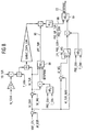
- the illustrated in Fig. 1 schematic structure of the control has an activation unit 10, which switch depending on the operating points of the internal combustion engine either in a controlled (closed-loop) or controlled (open-loop) operation.
- the activation conditions are dependent on the operating points of the internal combustion engine, which are determined either via a measurement or in the model of the air exhaust path 12.
- the setpoint unit 14 determines setpoint values which are dependent on the operating parameters of the internal combustion engine, the turbocharger, the ambient conditions and the calculated variables from the model 12. These setpoint values are additionally corrected dynamically in order to achieve an optimum adaptation of the setpoint value to unsteady operating states.
- the setpoints are forwarded to a pilot control unit 16 and to a controller 18.
- the pilot unit 16 may include a VTG model to drive the variable turbine geometry according to the predetermined setpoints.
- the controller can be designed as a conventional PI controller, which preferably has a parallel correction branch with DT 1 behavior. The controller compensates for inaccuracies of the pilot control and the model unit 12 for the air and exhaust path.
- a compressor model element 20 the power of the compressor is calculated from the thermodynamic conditions at the compressor.
- POW_CMP power of the compressor
- POW_TUR losses occurring at the shaft between the compressor and the turbine
- the sum of compressor power and power loss gives the turbine power (POW_TUR), which is applied as an input to the turbine model element 24.
- the turbine model element determines the duty cycle (BPAPWM) for variable turbine geometry (VTG) or WASTEGATE (WG). It will be apparent from the foregoing that the same view applies to the torques acting on the shaft.
- FIG. 3 shows the calculation of the compressor power (POW_CMP).
- the compressor power is the quotient of ambient pressure (AMP) 28 and pressure at the compressor (MAP) 26, the quotient 30 is applied to a characteristic KL 1 .
- the fresh air mass flow (MAF) 34 and the ambient temperature (TIA) 32 are also taken into account in the characteristic map KF 1 .
- the isentropic compressor efficiency (EFF_CMP) is determined. Taking into account the fresh air mass flow and the ambient temperature as well as the specific heat capacity of air can be calculated so the performance of the compressor. If the torque balance is to be considered instead of the power balance in FIG. 2, then the power of the compressor calculated in FIG. 3 is to be divided by the turbo speed (N_TCHA) and the factor 2 ⁇ .
- N_TCHA turbo speed
- T_UP_CMP 38 is also a Setpoint specification possible via the temperature ratio at the compressor.
- FIG. 4 illustrates that the compressor model explained with reference to FIG. 3 may also be used to derive the set point for the temperature from a desired value for the pressure at the compressor (MAP_SP) 40 and from a desired value for the fresh air mass flow (MAF_SP) after the compressor (T_UP_CMP_SP) 44 to calculate.
- MAP_SP pressure at the compressor
- MAF_SP fresh air mass flow
- T_UP_CMP_SP fresh air mass flow
- Fig. 5 shows the example of the power balance, the calculation of the power loss when no measurement of the turbine speed.
- the turbine speed (N_TCHA) 64 is determined using the map KF 2 depending on the pressure at the compressor (MAP) 56, the fresh air mass flow (MAF) 58, the ambient pressure (AMP) 60 and the ambient temperature (TIA) 62.
- MAP pressure at the compressor
- MAF fresh air mass flow
- AMP ambient pressure
- TIA ambient temperature
- N_TCHA_NOM the non-isentropic loss of the turbocharger
- Fig. 6 illustrates the calculation of the turbine torque in the event that the measured turbine speed (N_TCHA) 70 is known.
- the suitably normalized turbine speed can be used directly with the characteristic map KL 2 .
- An exemplary course for such a map is shown in the lower part of FIG. 6. It is shown that the non-isentropic losses of the turbocharger increase with the normalized turbine speed (N_TCHA / N_TCHA_NOM).
- FIG. 7 and 8 illustrate the calculation of the duty cycle (BPAPWM) 72 for the actuator. Both figures explain the calculation of the manipulated variable based on the turbine torque (TQ_TUR) 74. However, the same calculation can also be performed on the basis of the turbine power (POW_TUR) 74.
- the model shown in Fig. 7 allows a particularly simple switching for a WASTEGATE control.
- a control signal NC_WG
- NC_WG control signal
- a VTG control takes place in which the exhaust gas mass flow is used via the turbine (M_EXH) 76.
- M_WG mass flow over WASTEGATE 80
- M_TUR_MAX maximum mass flow across the turbine
- FIG. 8 shows the calculation of the manipulated variable 72 as a function of a characteristic map KF 4 84, which depends on the pressure ratio (DIV_PRS_TUR) 86 on the turbine.
- the pre-turbine exhaust pressure (PRS_EXH) and exhaust temperature (T_EXH) and mass flow over EGR values are estimated in the model of FIG. 8. It has been found that the sensitivity of the model to the manipulated variable 72 (BPAPWM), which on the one hand is the result of the model, on the other hand in the third characteristic field (KF 3 ) 88 is low, so that stable and accurate results are achieved.
- the manipulated variable 72 (duty cycle) on the third characteristic map it is also possible to use a position feedback of the wastegate or the VTG position on the characteristic map.
Description
Die Erfindung betrifft ein Verfahren zur Regelung eines Ladedrucks in einer Brennkraftmaschine mit einem Abgasturbolader.The invention relates to a method for regulating a boost pressure in an internal combustion engine with an exhaust gas turbocharger.
Ein Abgasturbolader (ATL) besteht aus zwei Strömungsmaschinen: einer Turbine und einem Verdichter, die auf einer gemeinsamen Welle angebracht sind. Die Turbine nutzt die im Abgas enthaltene Energie zum Antrieb des Verdichters, der Frischluft ansaugt und vorverdichtete Luft in die Zylinder einer Brennkraftmaschine drückt. Der Abgasturbolader ist durch den Luft- und Abgasmassenstrom strömungstechnisch mit der Brennkraftmaschine gekoppelt. Abgasturbolader werden bei Pkw-, Lkw- und Großbrennkraftmaschinen eingesetzt. Insbesondere bei Pkw-Abgasturboladern ist wegen des großen Drehzahlbereichs eine Regelung des Abgasturboladers erforderlich, um einen nahezu konstanten und genauen Ladedruck in einem weiteren Drehzahlbereich zu erzielen.An exhaust gas turbocharger (ATL) consists of two turbomachines: a turbine and a compressor, which are mounted on a common shaft. The turbine uses the energy contained in the exhaust gas to drive the compressor, which sucks fresh air and presses pre-compressed air into the cylinders of an internal combustion engine. The exhaust gas turbocharger is coupled by the air and exhaust gas mass flow fluidly with the internal combustion engine. Exhaust gas turbochargers are used in passenger car, truck and large combustion engines. In particular, in passenger car exhaust gas turbochargers, a regulation of the exhaust gas turbocharger is required because of the large speed range in order to achieve a nearly constant and accurate boost pressure in another speed range.
Um einen bestimmten Soll-Ladedruck bereitzustellen, sind Regel- und Steuervorrichtungen bekannt. Dabei muß berücksichtigt werden, daß der am Abgasturbolader erzeugte Ladedruck in der Regel vom Betriebspunkt der Brennkraftmaschine abhängt. Eine Möglichkeit, den Ladedruck eines Abgasturboladers zu beeinflussen, bieten Abgasturbolader mit variabler Turbinengeometrie (VTG). Die Steuerung des Ladedrucks mit Hilfe der variablen Turbinengeometrie erfolgt durch einen VTG-Steller, der unter Vorgabe einer Stellgröße angesteuert wird. Zur Ladedruckregelung ist es ebenfalls möglich, ein abgasseitig angeordnetes Ladedruckregelventil (WASTEGATE) zu verwenden. Bei dieser abgasseitigen Regelung wird ein Teil der Abgase um die Turbine herumgeführt, so daß abhängig von dem herumgeführten Abgasstrom ein geringerer Abgasstrom durch die Turbine strömt.In order to provide a certain desired boost pressure, control and regulating devices are known. It must be considered that the charge pressure generated at the exhaust gas turbocharger usually depends on the operating point of the internal combustion engine. One option for influencing the boost pressure of an exhaust gas turbocharger is provided by turbochargers with variable turbine geometry (VTG). The control of the boost pressure with the aid of the variable turbine geometry is carried out by a VTG controller, which is controlled by presetting a manipulated variable. For boost pressure control, it is also possible to use a wastegate arranged on the exhaust side (WASTEGATE). In this exhaust gas control part of the exhaust gases is guided around the turbine, so that depending on the bypassed exhaust gas flow, a smaller exhaust gas flow through the turbine.
Aus DE 197 09 955 A1 ist ein Verfahren zum Steuern einer Brennkraftmaschine bekannt, das mit einer Steuereinrichtung versehen ist, die physikalische Modelle einer Aufladeeinrichtung und eines Ansaugtrakts aufweist. Mit Hilfe dieser Modelle werden Schätzwerte für den Ladedruck und für den Luftmassenstrom in die Zylinder ermittelt, die zur Steuerung der Brennkraftmaschine dienen.From DE 197 09 955 A1 a method for controlling an internal combustion engine is known, which is provided with a control device having physical models of a charging device and an intake tract. With the help of these models estimated values for the boost pressure and for the air mass flow into the cylinders are determined, which serve to control the internal combustion engine.
Aus der DE 42 14 648 A1 ist ein Verfahren zum Steuern einer Brennkraftmaschine mit einem Turbolader und eine Abgasrückführung bekannt, bei dem durch Integration der Differenz zwischen den Leistungen des Verdichters und der Turbine des Turboladers die Drehzahl der Laderwelle bestimmt wird. Ausgehend von der Drehzahl der Laderwelle wird dann ein Ladedrucksignal berechnet. Das Ladedrucksignal wird dann zusammen mit weiteren Signalen zur Steuerung der Brennkraftmaschine verwendet.From
Der Erfindung liegt die Aufgabe zugrunde, ein Verfahren zur Regelung des Ladedrucks bereitzustellen, das mit einfachen Mitteln eine genaue und zuverlässige Einstellung des Ladedrucks ermöglicht.The invention has for its object to provide a method for controlling the boost pressure, which allows simple means an accurate and reliable adjustment of the boost pressure.
Die Aufgabe wird durch die Merkmale des Hauptanspruchs gelöst.The object is solved by the features of the main claim.
Erfindungsgemäß wird in dem Verfahren in einem ersten Schritt die Leistung oder das Drehmoment des Verdichters bestimmt. Leistung und Drehmoment des Verdichters sind über die Turboladerdrehzahl miteinander verknüpft, wobei das Drehmoment umgekehrt proportional zur Turboladerdrehzahl und proportional zur Leistung des Verdichters ist. Erfindungsgemäß werden in einem zweiten Schritt die bei der Übertragung von der Turbine auf den Verdichter auftretenden Leistungs- oder Drehmomentverluste bestimmt. Hierbei werden insbesondere Spaltverluste, Reibungsverluste der Welle usw. berücksichtigt. Zur Ermittlung der Verlustleistung bzw. des Verlustdrehmoments wird angenommen, daß die Verluste abhängig von der Leistung bzw. dem Drehmoment des Verdichters sind. Der Proportionalitätsfaktor ist abhängig von dem Betriebszustand und wird mit Hilfe einer Kennlinie bestimmt. In einem dritten Schritt wird aus den zuvor bestimmten Leistungen und Drehmomenten die Leistung bzw. das Drehmoment der Turbine bestimmt. Dieses ergibt sich direkt als Summe der beiden zuvor bestimmten physikalischen Größen. Abhängig von der Leistung oder dem Drehmoment der Turbine wird nun nachfolgend eine Sollwertvorgabe für die Stellgröße zur Einstellung des Ladedrucks ermittelt. Hierbei ist vorteilhaft, daß nicht nur die Parameter, die die Betriebszustände des Motors kennzeichnen, sondern auch die Zustände der Turbine berücksichtigt werden. Bei dem erfindungsgemäßen Verfahren wird der eindeutige thermodynamische Zustand der Turbine beschrieben. Dies ermöglicht eine schnelle und sehr genaue Einstellung bzw. Regelung des Ladedrucks bei einer Brennkraftmaschine mit ATL.According to the invention, the power or the torque of the compressor is determined in a first step in the method. The power and torque of the compressor are linked by the turbocharger speed, where the torque is inversely proportional to the turbocharger speed and proportional to the power of the compressor. According to the invention, the power or torque losses occurring during the transmission from the turbine to the compressor are determined in a second step. Here, in particular gap losses, frictional losses of the shaft, etc. are taken into account. To determine the power loss or the loss torque is assumed that the losses are dependent on the power or the torque of the compressor. The proportionality factor depends on the operating condition and is determined by means of a characteristic curve. In a third step, the power or the torque of the turbine is determined from the previously determined powers and torques. This results directly as the sum of the two previously determined physical quantities. Depending on the power or the torque of the turbine, a setpoint specification for the manipulated variable for setting the boost pressure will now be determined below. It is advantageous that not only the parameters that characterize the operating states of the engine, but also the states of the turbine are taken into account. In the method according to the invention, the unique thermodynamic state of the turbine is described. This allows a fast and very accurate adjustment of the boost pressure in an internal combustion engine with ATL.
In einer bevorzugten Ausgestaltung des Verfahrens wird die Leistung oder das Drehmoment des Verdichters unter Verwendung des isentropen Verdichterwirkungsgrades bestimmt, wobei der isentrope Verdichterwirkungsgrad durch ein erstes Kennfeld abhängig von dem Druck nach dem Verdichter und dem Frischluftmassenstrom sowie dem Umgebungsdruck und der Umgebungstemperatur bestimmt wird. Der isentrope Verdichterwirkungsgrad ist als ein erstes Kennfeld abhängig von dem Druckverhältnis zwischen Druck nach dem Verdichter und dem Umgebungsdruck und dem Quotienten aus Frischluftmassenstrom und Umgebungsdruck multipliziert mit der Wurzel aus der Umgebungstemperatur abgelegt.In a preferred embodiment of the method, the power or torque of the compressor is determined using the isentropic compressor efficiency, wherein the isentropic compressor efficiency is determined by a first map depending on the pressure after the compressor and the fresh air mass flow and the ambient pressure and the ambient temperature. The isentropic compressor efficiency is stored as a first map depending on the pressure ratio between the pressure after the compressor and the ambient pressure and the quotient of fresh air mass flow and ambient pressure multiplied by the root from the ambient temperature.
Sofern an dem Abgasturbolader keine Meßeinrichtung zur Messung der Turbinendrehzahl vorgesehen ist, wird der Wert der Turbinendrehzahl durch ein zweites Kennfeld abhängig von dem Massenstrom über den Verdichter, dem Abgasdruck nach dem Verdichter, Umgebungsdruck und der Abgastemperatur berechnet.If no measuring device for measuring the turbine speed is provided on the exhaust gas turbocharger, the value of the turbine speed is calculated by a second map depending on the mass flow through the compressor, the exhaust gas pressure after the compressor, ambient pressure and the exhaust gas temperature.
Zu einer genaueren Berechnung der Turbinendrehzahl, insbesondere bei einer variablen Turbinengeometrie kann das zweite Kennfeld zusätzlich von dem Wert der Stellgröße für den Ladedruck abhängen. Ebenfalls ist es möglich, daß die Turbinendrehzahl direkt an der Turbine gemessen wird. Bevorzugt erfolgt hier eine kontaktlose Messung der Turbinendrehzahl, wie beispielsweise eine induktive oder optische Messung.For a more accurate calculation of the turbine speed, in particular for a variable turbine geometry, the second map may additionally depend on the value of the control value for the boost pressure. It is also possible that the turbine speed is measured directly on the turbine. A contactless measurement of the turbine speed, such as, for example, an inductive or optical measurement, preferably takes place here.
Der Leistungs- oder der Drehmomentverlust wird abhängig von der Turbinendrehzahl über eine vorbestimmte Kennlinie ermittelt. Zur Ermittlung des Verlustes werden die nicht durch den isentropen Wirkungsgrad des Verdichters erfaßten Verluste in der Kennlinie berücksichtigt. Hierzu werden die Verluste abhängig von der Turbinendrehzahl dargestellt. Bevorzugt ist die Kennlinie nicht direkt abhängig von der Turbinendrehzahl dargestellt, sondern abhängig von der Turbinendrehzahl normiert auf die maximale Turbinendrehzahl.The power or torque loss is determined depending on the turbine speed over a predetermined characteristic. To determine the loss, the losses in the characteristic curve not detected by the isentropic efficiency of the compressor are taken into account. For this purpose, the losses are shown as a function of the turbine speed. The characteristic is preferably not directly dependent on the turbine speed, but is normalized to the maximum turbine speed depending on the turbine speed.
In einer Weiterführung des Verfahrens wird die Stellgröße abhängig von dem Druckverhältnis der Turbine ermittelt, das über eine polytrope Beziehung abhängig vom isentropen Wirkungsgrad der Turbine berechnet wird, wobei der isentrope Wirkungsgrad der Turbine unter Verwendung eines dritten Kennfeldes abhängig von dem Massenstrom über die Turbine, der Abgastemperatur und dem Abgasdruck vor der Turbine ermittelt wird. Zusätzlich wird bei dem dritten Kennfeld der Wert der Stellgröße für den Ladedruck berücksichtigt. Die Stellgröße selber wird über ein viertes Kennfeld abhängig von dem Abgasmassenstrom, dem Abgasdruck vor der Turbine und der Abgastemperatur, sowie dem Turbinendruckverhältnis ermittelt, wobei das Turbinendruckverhältnis wiederum von dem berechneten isentropen Wirkungsgrad der Turbine abhängt. Entscheidend ist hierbei, daß das vierte Kennfeld vom Turbinendruckverhältnis abhängt, was die Verwendung von bereits bekannten und zusammengestellten Turbinenkennfeldern vereinfacht.In a continuation of the method, the manipulated variable is determined depending on the pressure ratio of the turbine, which is calculated via a polytropic relationship depending on the isentropic efficiency of the turbine, wherein the isentropic efficiency of the turbine using a third map depending on the mass flow through the turbine, the Exhaust temperature and the exhaust pressure in front of the turbine is determined. In addition, the value of the control value for the boost pressure is taken into account in the third map. The manipulated variable itself is determined via a fourth map depending on the exhaust gas mass flow, the exhaust pressure upstream of the turbine and the exhaust gas temperature, and the turbine pressure ratio, the turbine pressure ratio in turn depends on the calculated isentropic efficiency of the turbine. Crucial here is that the fourth map depends on the turbine pressure ratio, which simplifies the use of already known and assembled turbine maps.
Alternativ hierzu ist es auch möglich, daß die Stellgröße durch ein Kennfeld abhängig von dem Temperaturverhältnis an der Turbine bestimmt wird, wobei dann die Größen des Abgasmassenstroms, des Abgasdrucks vor der Turbine und der Abgastemperatur berücksichtigt werden. Bei dieser Bestimmung der Stellgröße ist das Kennfeld abhängig von dem Temperaturverhältnis an der Turbine, wodurch einerseits eine Berechnung des isentropen Wirkungsgrades der Turbine unterbleiben kann, andererseits jedoch das vierte Kennfeld temperaturabhängig aufgestellt werden muß.Alternatively, it is also possible that the manipulated variable is determined by a map depending on the temperature ratio of the turbine, in which case the sizes of the exhaust gas mass flow, the exhaust pressure upstream of the turbine and the exhaust gas temperature are taken into account. In this determination of the manipulated variable, the characteristic field is dependent on the temperature ratio at the turbine, whereby on the one hand a calculation of the isentropic efficiency of the turbine can be omitted, on the other hand, however, the fourth characteristic field must be set up temperature-dependent.
Mit dem erfindungsgemäßen Verfahren wird der Ladedruck über eine Turbine mit einer variablen Turbinengeometrie oder über ein WASTEGATE mit einem Ventil eingestellt.With the method according to the invention, the boost pressure is set via a turbine with a variable turbine geometry or via a WASTEGATE with a valve.
Bei der Verwendung eines WASTEGATEs wird der über das WASTEGATE fließende Massenstrom als die Differenz aus Abgasmassenstrom und einem maximalen Turbinenmassenstrom gebildet, um die Turbine zu schützen.When using a WASTEGATE, the mass flow flowing through the WASTEGATE is formed as the difference between the exhaust mass flow and a maximum turbine mass flow to protect the turbine.
Ausführungsbeispiele der Erfindung werden im folgenden unter Bezugnahme auf die Zeichnungen näher erläutert. Es zeigen:
- Fig. 1
- einen schematischen Aufbau der Reglerstruktur,
- Fig. 2
- drei Funktionsblöcke für das Modell des Turboladers,
- Fig. 3
- die Bestimmung der Leistung des Verdichters einmal abhängig von den Drücken und einmal abhängig von der Temperatur,
- Fig. 4
- die Bestimmung von Sollwerten für das Temperaturverhältnis,
- Fig. 5
- die Berechnung der Turbinenleistung,
- Fig. 6
- die Berechnung des Turbinendrehmoments für den Fall, daß die Turbinendrehzahl gemessen wird,
- Fig. 7
- die Berechnung des Tastverhältnisses für das Stellglied, wenn das Temperaturverhältnis verwendet wird, und
- Fig. 8
- die Berechnung des Tastverhältnisses, wenn das Druckverhältnis an der Turbine der Berechnung des Tastverhältnisses zugrunde gelegt wird.
- Fig. 1
- a schematic structure of the controller structure,
- Fig. 2
- three function blocks for the turbocharger model,
- Fig. 3
- the determination of the capacity of the compressor once depending on the pressures and once depending on the temperature,
- Fig. 4
- the determination of setpoints for the temperature ratio,
- Fig. 5
- the calculation of the turbine power,
- Fig. 6
- the calculation of the turbine torque in the event that the turbine speed is measured
- Fig. 7
- the calculation of the duty cycle for the actuator when the temperature ratio is used, and
- Fig. 8
- the calculation of the duty cycle, if the pressure ratio at the turbine is used as a basis for calculating the duty cycle.
Der in Fig. 1 dargestellte schematische Aufbau der Regelung besitzt eine Aktivierungseinheit 10, die abhängig von den Betriebspunkten der Brennkraftmaschine entweder in einen geregelten (closed-loop) oder gesteuerten (open-loop) Betrieb schalten. Die Aktivierungsbedingungen sind abhängig von den Betriebspunkten der Brennkraftmaschine, die entweder über eine Messung oder in dem Modell des Luft-Abgaspfades 12 ermittelt werden.The illustrated in Fig. 1 schematic structure of the control has an
Die Sollwerteinheit 14 bestimmt Sollwerte, die abhängig von den Betriebsparametern der Brennkraftmaschine, des Turboladers, den Umgebungsbedingungen und den berechneten Größen aus dem Modell 12 sind. Diese Sollwerte werden zusätzlich noch dynamisch korrigiert, um eine optimale Anpassung des Sollwertes an instationäre Betriebszustände zu erreichen. Die Sollwerte werden an eine Vorsteuereinheit 16 und an einen Regler 18 weitergeleitet. Die Vorsteuereinheit 16 kann beispielsweise ein VTG-Modell enthalten, um die variable Turbinengeometrie gemäß den vorgegebenen Sollwerten anzusteuern.The
In der Modelleinheit 12 für den Luft- und Abgaspfad werden die nicht gemessenen Zustände im Luft-Abgaspfad ermittelt und den übrigen Einheiten 10, 14, 16 und 18 zur Verfügung gestellt. Der Regler kann als ein konventioneller PI-Regler ausgebildet sein, der vorzugsweise einen parallelen Korrekturzweig mit DT1-Verhalten besitzt. Mit dem Regler werden Ungenauigkeiten der Vorsteuerung und der Modelleinheit 12 für den Luft- und Abgaspfad kompensiert.In the
Die Modellstruktur wird mit Bezug auf Fig. 2 am Beispiel der Leistungsbilanz näher beschrieben. In einem Verdichter-Modellelement 20 wird die Leistung des Verdichters über die thermodynamischen Zustände am Verdichter berechnet. Um diese Leistung des Verdichters (POW_CMP) in die Leistung der Turbine (POW_TUR) umrechnen zu können, wird in einem Verlust-Modellelement 22 die an der Welle zwischen Verdichter und Turbine auftretenden Verluste berechnet. Die Summe aus Verdichterleistung und Verlustleistung ergibt die Turbinenleistung (POW_TUR), die als Eingangsgröße an das Turbinen-Modellelement 24 anliegt. Das Turbinen-Modellelement bestimmt das Tastverhältnis (BPAPWM) für die variable Turbinengeometrie (VTG) oder das WASTEGATE (WG). Aus dem Vorstehenden wird deutlich, daß dieselbe Betrachtungsweise für die an der Welle angreifenden Drehmomente gilt.The model structure will be described in more detail with reference to FIG. 2 using the example of the power balance. In a
Nachfolgend werden die einzelnen Modellelemente im Detail erläutert. Fig. 3 zeigt die Berechnung der Verdichterleistung (POW_CMP). In die Verdichterleistung geht ein der Quotient aus Umgebungsdruck (AMP) 28 und Druck am Verdichter (MAP) 26, deren Quotient 30 an einer Kennlinie KL1 anliegt. Die Kennlinie KL1 berechnet die folgende Größe: 
wobei CAPA_MAF den isentropen Exponenten von Luft bezeichnet.The individual model elements are explained in detail below. 3 shows the calculation of the compressor power (POW_CMP). In the compressor power is the quotient of ambient pressure (AMP) 28 and pressure at the compressor (MAP) 26, the
where CAPA_MAF denotes the isentropic exponent of air.
Zusätzlich zu dem Umgebungsdruck (AMP) 28 wird in dem Kennfeld KF1 noch der Frischluftmassenstrom (MAF) 34 und die Umgebungstemperatur (TIA) 32 berücksichtigt. In dem Kennfeld KF1 36 wird der isentrope Verdichter-Wirkungsgrad (EFF_CMP) bestimmt. Unter Berücksichtigung des Frischluftmassenstroms und der Umgebungstemperatur sowie der spezifischen Wärmekapazität von Luft läßt sich so die Leistung des Verdichters berechnen. Soll statt der Leistungsbilanz in Fig. 2 die Drehmomentbilanz betrachtet werden, so ist die in Fig. 3 berechnete Leistung des Verdichters durch die Turbodrehzahl (N_TCHA) und den Faktor 2π zu dividieren. Bei einem vorhandenen Sollwert der Temperatur nach dem Verdichter (T_UP_CMP) 38 ist auch eine Sollwertvorgabe über das Temperaturverhältnis am Verdichter möglich.In addition to the ambient pressure (AMP) 28, the fresh air mass flow (MAF) 34 and the ambient temperature (TIA) 32 are also taken into account in the characteristic map KF 1 . In the
Fig. 4 verdeutlicht, daß das mit Bezug auf Fig. 3 erläuterte Verdichtermodell ebenfalls dazu verwendet werden kann, um aus einem Sollwert für den Druck am Verdichter (MAP_SP) 40 und aus einem Sollwert für den Frischluftmassenstrom (MAF_SP) 42 den Sollwert für die Temperatur nach dem Verdichter (T_UP_CMP_SP) 44 zu berechnen.FIG. 4 illustrates that the compressor model explained with reference to FIG. 3 may also be used to derive the set point for the temperature from a desired value for the pressure at the compressor (MAP_SP) 40 and from a desired value for the fresh air mass flow (MAF_SP) after the compressor (T_UP_CMP_SP) 44 to calculate.
Die beiden Möglichkeiten zur Berechnung der Verluste werden mit Bezug auf die Figuren 5 und 6 beschrieben. Fig. 5 zeigt am Beispiel der Leistungsbilanz die Berechnung der Verlustleistung, wenn keine Messung der Turbinendrehzahl erfolgt. In diesem Fall wird mit Hilfe des Kennfeldes KF2 abhängig von dem Druck am Verdichter (MAP) 56, dem Frischluftmassenstrom (MAF) 58, dem Umgebungsdruck (AMP) 60 und der Umgebungstemperatur (TIA) 62 die Turbinendrehzahl (N_TCHA) 64 bestimmt. Bezogen auf eine normierte Turbinendrehzahl (N_TCHA_NOM) 66 kann über die Kennlinie KL2 der nicht isentrope Verlust des Turboladers (EFF_LOSS_TCHA) 68 berechnet werden. Die Verlustleistung des Abgasturboladers ergibt sich damit zu: ![]()
![]()
Fig. 6 erläutert die Berechnung des Turbinendrehmoments für den Fall, daß die gemessene Turbinendrehzahl (N_TCHA) 70 bekannt ist. Im Vergleich zu der mit Bezug auf Fig. 5 beschriebenen Berechnung kann hierbei direkt die geeignet normierte Turbinendrehzahl mit dem Kennfeld KL2 benutzt werden. Ein beispielhafter Verlauf für ein solches Kennfeld ist im unteren Teil der Fig. 6 wiedergegeben. Es ist dargestellt, daß die nicht isentropen Verluste des Turboladers mit der normierten Turbinendrehzahl (N_TCHA/N_TCHA_NOM) steigen.Fig. 6 illustrates the calculation of the turbine torque in the event that the measured turbine speed (N_TCHA) 70 is known. In comparison with the calculation described with reference to FIG. 5, the suitably normalized turbine speed can be used directly with the characteristic map KL 2 . An exemplary course for such a map is shown in the lower part of FIG. 6. It is shown that the non-isentropic losses of the turbocharger increase with the normalized turbine speed (N_TCHA / N_TCHA_NOM).
Die Figuren 7 und 8 erläutern die Berechnung des Tastverhältnisses (BPAPWM) 72 für das Stellglied. Beide Figuren erläutern die Berechnung der Stellgröße anhand des Turbinendrehmoments (TQ_TUR) 74. Jedoch kann die gleiche Berechnung auch ausgehend von der Turbinenleistung (POW_TUR) 74 ausgeführt werden. In der in Fig. 7 dargestellten Berechnung wird die Stellgröße 72 (BPAPWM) abhängig von dem Temperaturverhältnis (DIV_T_TUR = T_UP_TDR/T_EXH) berechnet. Das vierte Kennfeld KF4 hat die folgenden Abhängigkeiten: 
wobei T_UP_TUR die Temperatur nach der Turbine, T_EXH die Abgastemperatur, M_EXH den Abgasmassenstrom über die Turbine und PRS_EXH den Abgasdruck vor der Turbine bezeichnet.Figures 7 and 8 illustrate the calculation of the duty cycle (BPAPWM) 72 for the actuator. Both figures explain the calculation of the manipulated variable based on the turbine torque (TQ_TUR) 74. However, the same calculation can also be performed on the basis of the turbine power (POW_TUR) 74. In the calculation illustrated in FIG. 7, the manipulated variable 72 (BPAPWM) is calculated as a function of the temperature ratio (DIV_T_TUR = T_UP_TDR / T_EXH). The fourth map KF 4 has the following dependencies:
where T_UP_TUR is the temperature after the turbine, T_EXH the exhaust gas temperature, M_EXH the exhaust gas mass flow through the turbine, and PRS_EXH the exhaust gas pressure upstream of the turbine.
Abhängig von dem Druckverhältnis (DIV_PRS_TUR = PRS_UP_TUR/PRS_EXH) hat das vierte Kennfeld die folgende Gestalt: 
Das in Fig. 7 dargestellte Modell ermöglicht eine besonders einfache Umschaltung für eine WASTEGATE-Steuerung. Ansprechend auf ein Steuersignal (NC_WG) wird zwischen zwei Zuständen hin und her geschaltet. Bei der in Fig. 7 dargestellten Verbindung erfolgt eine VTG-Steuerung, bei der der Abgasmassenstrom über die Turbine (M_EXH) 76 verwendet wird. Bei einer WASTEGATE-Steuerung wird ansprechend auf das Steuersignal 74 der Kontakt mit dem Anschluß 78 hergestellt, so daß der Massenstrom über das WASTEGATE 80 (M_WG) an die Stelle des Abgasstroms über die Turbine tritt. Der Massenstrom über das WASTEGATE ergibt sich als der Massenstrom über die Turbine minus einem maximalen Massenstrom über die Turbine (M_TUR_MAX) 82. Die Verwendung des maximalen Massenstroms über die Turbine 82 ermöglicht es, die Turbine vor einer Zerstörung durch einen zu großen Massenstrom zu schützen.The model shown in Fig. 7 allows a particularly simple switching for a WASTEGATE control. In response to a control signal (NC_WG) is switched between two states back and forth. In the connection illustrated in FIG. 7, a VTG control takes place in which the exhaust gas mass flow is used via the turbine (M_EXH) 76. In a WASTEGATE controller, contact with
Fig. 8 zeigt die Berechnung der Stellgröße 72 abhängig von einem Kennfeld KF4 84, das von dem Druckverhältnis (DIV_PRS_TUR) 86 an der Turbine abhängt. Zur Bestimmung des Druckverhältnisses 86 wird mit Hilfe des dritten Kennfeldes (KF3) 88 der isentrope Turbinenwirkungsgrad 90 berechnet. Dieser kann über die Kennlinie KL3 (polytropen Beziehung zwischen Temperatur- und Druckverhältnis) in das Druckverhältnis wie folgt umgerechnet werden: 
Die Werte für den Abgasdruck vor der Turbine (PRS_EXH) und die Abgastemperatur (T_EXH) sowie den Massenstrom über EGR werden in dem Modell aus Fig. 8 geschätzt. Es hat sich herausgestellt, daß die Sensitivität des Modells auf die Stellgröße 72 (BPAPWM), die einerseits Ergebnis des Modells ist, andererseits in dem dritten Kennfeld (KF3) 88 eingeht, gering ist, so daß stabile und genaue Ergebnisse erzielt werden. Alternativ zur Stellgröße 72 (Tastverhältnis) am dritten Kennfeld kann auch eine Lagerückmeldung des Wastegates oder der VTG-Stellung an dem Kennfeld verwendet werden.The pre-turbine exhaust pressure (PRS_EXH) and exhaust temperature (T_EXH) and mass flow over EGR values are estimated in the model of FIG. 8. It has been found that the sensitivity of the model to the manipulated variable 72 (BPAPWM), which on the one hand is the result of the model, on the other hand in the third characteristic field (KF 3 ) 88 is low, so that stable and accurate results are achieved. As an alternative to the manipulated variable 72 (duty cycle) on the third characteristic map, it is also possible to use a position feedback of the wastegate or the VTG position on the characteristic map.
Claims (12)
- Method for controlling a charge pressure in an internal combustion engine with an exhaust gas turbocharger consisting of a turbine and a charge air compressor in which a manipulated variable is determined for setting the charge pressure which is emitted by the charge air compressor and has the following method steps:- in a first step the power or the torque of the compressor (POW_CMP, TQ_CMP) is determined,- in a second step, the power or torque loss (POW_LOSS_TCHA, TQ_LOSS_TCHA) which occurs during the transmission from the turbine to the compressor is determined, and- in a third step the power or the torque of the turbine (POW_TUR, TQ_TUR) is determined from the power or the torque of the compressor and the power or torque loss, and a predefined setpoint value is determined for the manipulated variable (BPAPWM) as a function of the power or the torque of the turbine.
- Method according to Claim 1, characterized in that the power or the torque of the compressor is determined using an isentropic compressor efficiency level (EFF_CMP),
the isentropic compressor efficiency level being determined by means of a first characteristic diagram (KF1) as a function of the following variables:pressure downstream of the compressor (MAP),fresh air mass flow rate (MAF) fed to the internal combustion engine,ambient pressure (AMP) andambient temperature (TIA). - Method according to Claim 1 or 2, characterized in that the rotational speed (N_TCHA) of the turbine is calculated,
the value of the rotational speed of the turbine being calculated by means of a second characteristic diagram (KF2) as a function of the following variables,
mass flow rate across the compressor (MAF),
exhaust gas pressure downstream of the compressor, ambient pressure (AMP), and
ambient temperature (TIA). - Method according to Claim 3, characterized in that the second characteristic diagram (KF2) additionally depends on the value of the manipulated variable (BPAPWH) for the charge pressure.
- Method according to Claim 1 or 2, characterized in that the rotational speed (N_TCHA) of the turbine is measured.
- Method according to one of Claims 3 to 5, characterized in that the power or torque loss is determined as a function of the rotational speed (N_TCHA) of the turbine by means of a predetermined characteristic curve.
- Method according to one of Claims 1 to 6, characterized in that the manipulated variable (BPAPWH) for the charge pressure is determined as a function of the isentropic efficiency level of the turbine, and the isentropic efficiency level of the turbine (EFF_TUR) is determined using a third characteristic diagram (KF3) as a function of the following variables:- mass flow rate across the turbine (M_TUR),- exhaust gas temperature (T_EXH) and- exhaust gas pressure upstream of the turbine (PRS_EXH),- the third characteristic diagram (KF3) depending additionally on the value of the manipulated variable (BPAPWH) for the charge pressure.
- Method according to Claim 7, characterized in that the manipulated variable (BPAPWH) for the charge pressure is calculated by a fourth characteristic diagram (KF4) as a function of the following variables:- exhaust gas mass flow rate (M_EXH),- exhaust gas pressure upstream of the turbine (PRS_EXH) and- exhaust gas temperature (T_EXH),and a turbine pressure ratio (DIV_PRS_TUR) which depends on the isentropic efficiency level of the turbine which is determined.
- Method according to one of Claims 1 to 6, characterized in that the manipulated variable (BPAPWH) for the charge pressure is determined by means of a characteristic diagram (KF4) as a function of the temperature ratio at the turbine (DIV_T_TUR) and the following variables:- exhaust gas mass flow rate (M_EXH),- exhaust gas pressure upstream of the turbine (PRS_EXH) and- exhaust gas temperature (T_EXH).
- Method according to one Claims 1 to 9, characterized in that the manipulated variable (BPAPWH) for the charge pressure acts on a variable turbine geometry.
- Method according to one of Claims 1 to 9, characterized in that the manipulated variable (BPAPWH) for the charge pressure acts on a charge pressure valve (WASTEGATE) which is arranged at the exhaust gas end.
- Method according to Claim 11, characterized in that the mass flow rate across the charge pressure valve (M_WG) is obtained as the difference between the exhaust gas mass flow rate (M_EXH) and a maximum turbine mass flow rate (M_TUR_MAX).
Applications Claiming Priority (3)
| Application Number | Priority Date | Filing Date | Title |
|---|---|---|---|
| DE10033114 | 2000-07-07 | ||
| DE10033114 | 2000-07-07 | ||
| PCT/DE2001/002328 WO2002004799A1 (en) | 2000-07-07 | 2001-06-25 | Method for controlling a charge pressure in an internal combustion engine with an exhaust-gas turbocharger |
Publications (2)
| Publication Number | Publication Date |
|---|---|
| EP1299628A1 EP1299628A1 (en) | 2003-04-09 |
| EP1299628B1 true EP1299628B1 (en) | 2006-08-02 |
Family
ID=7648168
Family Applications (1)
| Application Number | Title | Priority Date | Filing Date |
|---|---|---|---|
| EP01951425A Expired - Lifetime EP1299628B1 (en) | 2000-07-07 | 2001-06-25 | Method for controlling a charge pressure in an internal combustion engine with an exhaust-gas turbocharger |
Country Status (4)
| Country | Link |
|---|---|
| US (1) | US6732523B2 (en) |
| EP (1) | EP1299628B1 (en) |
| DE (1) | DE50110631D1 (en) |
| WO (1) | WO2002004799A1 (en) |
Families Citing this family (36)
| Publication number | Priority date | Publication date | Assignee | Title |
|---|---|---|---|---|
| DE10145038A1 (en) * | 2001-09-13 | 2003-04-03 | Bosch Gmbh Robert | Method and device for operating at least one supercharger of an internal combustion engine |
| US7058556B2 (en) * | 2001-09-26 | 2006-06-06 | Goodrich Pump & Engine Control Systems, Inc. | Adaptive aero-thermodynamic engine model |
| DE10243268A1 (en) * | 2002-09-18 | 2004-03-25 | Robert Bosch Gmbh | Control of vehicle engine supercharging, adapts limiting value by modification as function of second, characteristic operational magnitude |
| DE10318243A1 (en) * | 2003-04-23 | 2004-11-11 | Robert Bosch Gmbh | Method and device for operating an internal combustion engine |
| DE10319347A1 (en) * | 2003-04-30 | 2004-11-18 | Robert Bosch Gmbh | Method and device for operating an internal combustion engine |
| DE10320977A1 (en) * | 2003-05-09 | 2004-12-09 | Siemens Ag | Procedure for monitoring the speed of a bi-turbocharger |
| FR2858659B1 (en) * | 2003-08-06 | 2006-03-17 | Peugeot Motocycles Sa | SYSTEM FOR MONITORING THE OPERATION OF A MOTOR OF A TWO-WHEEL VEHICLE OF THE SCOOTER TYPE. |
| DE102004015742A1 (en) * | 2004-03-31 | 2005-10-27 | Robert Bosch Gmbh | Method and device for operating an internal combustion engine |
| DE102004016010A1 (en) * | 2004-04-01 | 2005-10-20 | Bosch Gmbh Robert | Method and device for operating an internal combustion engine |
| DE102004051837B4 (en) * | 2004-10-25 | 2006-11-09 | Siemens Ag | Methods and apparatus for controlling and diagnosing an exhaust gas turbocharger |
| FR2882576B1 (en) * | 2005-02-28 | 2007-05-25 | Renault Sas | OPTIMIZED TRANSIENT PHASE CONTROL METHOD IN A TURBOCHARGER |
| DE102005054524A1 (en) * | 2005-11-14 | 2007-05-16 | Porsche Ag | Method and control unit for controlling a turbocharger with controllable turbine flow cross section |
| US7668704B2 (en) * | 2006-01-27 | 2010-02-23 | Ricardo, Inc. | Apparatus and method for compressor and turbine performance simulation |
| JP4673818B2 (en) * | 2006-10-26 | 2011-04-20 | トヨタ自動車株式会社 | Control device for turbocharged internal combustion engine |
| FR2910055B1 (en) * | 2006-12-15 | 2010-09-24 | Peugeot Citroen Automobiles Sa | METHOD FOR DETERMINING A PRESSURE INTO A TURBO-PRESSURE TURBINE EQUIPPED WITH A THERMAL ENGINE |
| FR2910059A1 (en) * | 2006-12-19 | 2008-06-20 | Renault Sas | Exhaust gas pressure estimating method for oil engine of motor vehicle, involves estimating pressure of exhaust gas in upstream of turbine by choosing one of two formulas comprising parameters e.g. pressure of gas in downstream of turbine |
| US7730724B2 (en) * | 2007-05-10 | 2010-06-08 | Ford Global Technologies, Llc | Turbocharger shaft over-speed compensation |
| FR2921114B1 (en) * | 2007-09-13 | 2018-01-12 | Peugeot Citroen Automobiles Sa | METHOD FOR DETERMINING A PRESSURE INTO A TURBO-PRESSURE TURBINE EQUIPPED WITH A THERMAL ENGINE |
| FR2921691B1 (en) * | 2007-09-28 | 2012-08-17 | Inst Francais Du Petrole | METHOD FOR CONTROLLING A TURBOCHARGER USING A PHYSICAL MODEL OF THE TURBOCHARGER REGIME |
| US7788922B2 (en) * | 2007-10-04 | 2010-09-07 | Delphi Technologies, Inc. | System and method for model based boost control of turbo-charged engines |
| US7748217B2 (en) * | 2007-10-04 | 2010-07-06 | Delphi Technologies, Inc. | System and method for modeling of turbo-charged engines and indirect measurement of turbine and waste-gate flow and turbine efficiency |
| FR2923538A3 (en) * | 2007-11-12 | 2009-05-15 | Renault Sas | Turbine upstream pressure estimating system for supercharged oil engine of motor vehicle, has calculation units calculating expansion ratio of turbine from magnitude representing temperature variation to deduce upstream pressure of turbine |
| DE102008054926B4 (en) * | 2007-12-19 | 2019-08-14 | Denso Corporation | Device for controlling a forced-filled engine |
| JP4853471B2 (en) * | 2007-12-19 | 2012-01-11 | 株式会社デンソー | Control device for an internal combustion engine with a supercharger |
| DE102008017164B3 (en) * | 2008-04-03 | 2009-08-06 | Continental Automotive Gmbh | Device for controlling an exhaust gas turbocharging of an internal combustion engine and internal combustion engine |
| US8090456B2 (en) * | 2008-11-03 | 2012-01-03 | United Technologies Corporation | System and method for design and control of engineering systems utilizing component-level dynamic mathematical model |
| FR2945318B1 (en) * | 2009-05-06 | 2011-04-29 | Renault Sas | SYSTEM AND METHOD FOR CONTROLLING OVER-POWERING OF AN INTERNAL COMBUSTION ENGINE |
| US8302397B2 (en) * | 2009-08-11 | 2012-11-06 | GM Global Technology Operations LLC | Mode transition systems and methods for a sequential turbocharger |
| US8668434B2 (en) * | 2009-09-02 | 2014-03-11 | United Technologies Corporation | Robust flow parameter model for component-level dynamic turbine system control |
| US8315741B2 (en) * | 2009-09-02 | 2012-11-20 | United Technologies Corporation | High fidelity integrated heat transfer and clearance in component-level dynamic turbine system control |
| DE102010050161A1 (en) * | 2010-10-30 | 2012-05-03 | Volkswagen Ag | Method for determining a pressure at the outlet of an exhaust system |
| GB2511767B (en) * | 2013-03-12 | 2017-04-26 | Gm Global Tech Operations | Method and system for controlling a boost pressure of a turbocharged internal combustion engine |
| US10584630B2 (en) * | 2016-06-06 | 2020-03-10 | Fca Us Llc | Power-based turbocharger boost control techniques |
| FR3063108A1 (en) * | 2017-02-17 | 2018-08-24 | Peugeot Citroen Automobiles Sa | METHOD FOR DETERMINING THE EXHAUST GAS TEMPERATURE BEYOND THE TURBINE OF A TURBOCHARGER COMPRISING A THERMAL ENGINE |
| FR3088371A1 (en) * | 2018-11-08 | 2020-05-15 | Psa Automobiles Sa | METHOD FOR DETERMINING THE POSITION OF A VARIABLE GEOMETRIC TURBINE ADJUSTING MEMBER |
| US11454180B1 (en) | 2021-06-17 | 2022-09-27 | Cummins Inc. | Systems and methods for exhaust gas recirculation |
Family Cites Families (7)
| Publication number | Priority date | Publication date | Assignee | Title |
|---|---|---|---|---|
| US4426982A (en) * | 1980-10-08 | 1984-01-24 | Friedmann & Maier Aktiengesellschaft | Process for controlling the beginning of delivery of a fuel injection pump and device for performing said process |
| US5186081A (en) * | 1991-06-07 | 1993-02-16 | General Motors Corporation | Method of regulating supercharger boost pressure |
| DE4214648A1 (en) | 1992-05-02 | 1993-11-04 | Bosch Gmbh Robert | SYSTEM FOR CONTROLLING AN INTERNAL COMBUSTION ENGINE |
| US6161384A (en) * | 1994-05-02 | 2000-12-19 | Waukesha Engine Division, Dresser Equipment Group, Inc. | Turbocharger control management system throttle reserve control |
| DE4417647A1 (en) * | 1994-05-20 | 1995-11-23 | Bosch Gmbh Robert | System for power control or power regulation of a supercharged internal combustion engine |
| DE19607773A1 (en) * | 1996-03-01 | 1997-09-04 | Bosch Gmbh Robert | Electromagnetically operated directional valve |
| DE19709955C2 (en) | 1997-03-11 | 2003-10-02 | Siemens Ag | Method and device for controlling an internal combustion engine |
-
2001
- 2001-06-25 EP EP01951425A patent/EP1299628B1/en not_active Expired - Lifetime
- 2001-06-25 DE DE50110631T patent/DE50110631D1/en not_active Expired - Lifetime
- 2001-06-25 WO PCT/DE2001/002328 patent/WO2002004799A1/en active IP Right Grant
-
2002
- 2002-12-31 US US10/334,332 patent/US6732523B2/en not_active Expired - Lifetime
Also Published As
| Publication number | Publication date |
|---|---|
| EP1299628A1 (en) | 2003-04-09 |
| US20030101723A1 (en) | 2003-06-05 |
| WO2002004799A1 (en) | 2002-01-17 |
| DE50110631D1 (en) | 2006-09-14 |
| US6732523B2 (en) | 2004-05-11 |
Similar Documents
| Publication | Publication Date | Title |
|---|---|---|
| EP1299628B1 (en) | Method for controlling a charge pressure in an internal combustion engine with an exhaust-gas turbocharger | |
| DE102008017164B3 (en) | Device for controlling an exhaust gas turbocharging of an internal combustion engine and internal combustion engine | |
| EP1247016B1 (en) | Method and device for controlling an internal combustion engine that is provided with an air system | |
| EP1440231B1 (en) | Method and device for controlling an electrically driven charger | |
| DE102005013977B4 (en) | Exhaust gas recirculation system for a motor vehicle and method for setting the exhaust gas recirculation rate in a gas recirculation system | |
| EP1427929B1 (en) | Method and device for operating at least one turbocharger on an internal combustion engine | |
| DE10329763B4 (en) | Coordinated control of an electronic throttle and a variable geometry turbocharger in supercharged and stoichiometric gasoline engines | |
| EP1809876B1 (en) | Method and device for controlling or regulating the boost pressure of an internal combustion engine comprising a compressor | |
| EP1623103B1 (en) | Method for monitoring the speed of a bi-turbocharger | |
| DE102015200906B4 (en) | Control device and control method for an internal combustion engine with a supercharger | |
| DE10310221A1 (en) | Method for limiting a boost pressure | |
| WO1999014476A1 (en) | Method and device for determining the gas intake in an internal combustion engine | |
| EP0046872B1 (en) | Combustion piston engine with exhaust gas turbocharger | |
| EP1002192A1 (en) | Method and device for protecting a turbo-supercharger | |
| EP1409855A1 (en) | Internal combustion engine comprising a secondary air charge and a method for controlling the secondary air-charge assembly | |
| DE102004003378B4 (en) | Control and control apparatus and control method for a multi-stage turbocharger | |
| DE3438176C2 (en) | Device for regulating the boost pressure of an internal combustion engine | |
| EP3594480B1 (en) | Method for controlling a charging system | |
| DE3411496A1 (en) | Device for control of the supercharging in an internal combustion engine | |
| EP1076166A2 (en) | Method and apparatus for the determination of the intake air in an internal combustion engine | |
| DE102015210226A1 (en) | Method and apparatus for increasing the performance of an internal combustion engine by using a turbocharger speed model and a turbocharger speed sensor | |
| DE19804466C2 (en) | Method for controlling an exhaust gas turbocharger with variable turbine geometry | |
| EP0728922B1 (en) | Controller with adapted integral part for the air mass flow of a turbocharged internal combustion engine | |
| EP2469061B1 (en) | Method and control equipment for determining a carbon black loading of a particulate filter | |
| DE102019109364A1 (en) | CONTROL OF THE COMPRESSOR PRESSURE RATIO |
Legal Events
| Date | Code | Title | Description |
|---|---|---|---|
| PUAI | Public reference made under article 153(3) epc to a published international application that has entered the european phase |
Free format text: ORIGINAL CODE: 0009012 |
|
| 17P | Request for examination filed |
Effective date: 20021227 |
|
| AK | Designated contracting states |
Kind code of ref document: A1 Designated state(s): AT BE CH CY DE DK ES FI FR GB GR IE IT LI LU MC NL PT SE TR |
|
| RBV | Designated contracting states (corrected) |
Designated state(s): DE FR GB IT |
|
| GRAP | Despatch of communication of intention to grant a patent |
Free format text: ORIGINAL CODE: EPIDOSNIGR1 |
|
| GRAS | Grant fee paid |
Free format text: ORIGINAL CODE: EPIDOSNIGR3 |
|
| GRAA | (expected) grant |
Free format text: ORIGINAL CODE: 0009210 |
|
| AK | Designated contracting states |
Kind code of ref document: B1 Designated state(s): DE FR GB IT |
|
| PG25 | Lapsed in a contracting state [announced via postgrant information from national office to epo] |
Ref country code: IT Free format text: LAPSE BECAUSE OF FAILURE TO SUBMIT A TRANSLATION OF THE DESCRIPTION OR TO PAY THE FEE WITHIN THE PRESCRIBED TIME-LIMIT;WARNING: LAPSES OF ITALIAN PATENTS WITH EFFECTIVE DATE BEFORE 2007 MAY HAVE OCCURRED AT ANY TIME BEFORE 2007. THE CORRECT EFFECTIVE DATE MAY BE DIFFERENT FROM THE ONE RECORDED. Effective date: 20060802 |
|
| REG | Reference to a national code |
Ref country code: GB Ref legal event code: FG4D Free format text: NOT ENGLISH |
|
| REF | Corresponds to: |
Ref document number: 50110631 Country of ref document: DE Date of ref document: 20060914 Kind code of ref document: P |
|
| GBT | Gb: translation of ep patent filed (gb section 77(6)(a)/1977) |
Effective date: 20061018 |
|
| ET | Fr: translation filed | ||
| PLBE | No opposition filed within time limit |
Free format text: ORIGINAL CODE: 0009261 |
|
| STAA | Information on the status of an ep patent application or granted ep patent |
Free format text: STATUS: NO OPPOSITION FILED WITHIN TIME LIMIT |
|
| 26N | No opposition filed |
Effective date: 20070503 |
|
| PGFP | Annual fee paid to national office [announced via postgrant information from national office to epo] |
Ref country code: IT Payment date: 20080624 Year of fee payment: 8 |
|
| PGFP | Annual fee paid to national office [announced via postgrant information from national office to epo] |
Ref country code: FR Payment date: 20080613 Year of fee payment: 8 |
|
| PGFP | Annual fee paid to national office [announced via postgrant information from national office to epo] |
Ref country code: GB Payment date: 20080620 Year of fee payment: 8 |
|
| GBPC | Gb: european patent ceased through non-payment of renewal fee |
Effective date: 20090625 |
|
| REG | Reference to a national code |
Ref country code: FR Ref legal event code: ST Effective date: 20100226 |
|
| PG25 | Lapsed in a contracting state [announced via postgrant information from national office to epo] |
Ref country code: FR Free format text: LAPSE BECAUSE OF NON-PAYMENT OF DUE FEES Effective date: 20090630 |
|
| PG25 | Lapsed in a contracting state [announced via postgrant information from national office to epo] |
Ref country code: GB Free format text: LAPSE BECAUSE OF NON-PAYMENT OF DUE FEES Effective date: 20090625 |
|
| PG25 | Lapsed in a contracting state [announced via postgrant information from national office to epo] |
Ref country code: IT Free format text: LAPSE BECAUSE OF NON-PAYMENT OF DUE FEES Effective date: 20090625 |
|
| PGFP | Annual fee paid to national office [announced via postgrant information from national office to epo] |
Ref country code: DE Payment date: 20180630 Year of fee payment: 18 |
|
| REG | Reference to a national code |
Ref country code: DE Ref legal event code: R119 Ref document number: 50110631 Country of ref document: DE |
|
| PG25 | Lapsed in a contracting state [announced via postgrant information from national office to epo] |
Ref country code: DE Free format text: LAPSE BECAUSE OF NON-PAYMENT OF DUE FEES Effective date: 20200101 |