EP1298890A2 - Foldable portable information terminal - Google Patents
Foldable portable information terminal Download PDFInfo
- Publication number
- EP1298890A2 EP1298890A2 EP02021875A EP02021875A EP1298890A2 EP 1298890 A2 EP1298890 A2 EP 1298890A2 EP 02021875 A EP02021875 A EP 02021875A EP 02021875 A EP02021875 A EP 02021875A EP 1298890 A2 EP1298890 A2 EP 1298890A2
- Authority
- EP
- European Patent Office
- Prior art keywords
- unit
- information terminal
- display
- portable information
- foldable portable
- Prior art date
- Legal status (The legal status is an assumption and is not a legal conclusion. Google has not performed a legal analysis and makes no representation as to the accuracy of the status listed.)
- Granted
Links
Images





Classifications
-
- H—ELECTRICITY
- H04—ELECTRIC COMMUNICATION TECHNIQUE
- H04M—TELEPHONIC COMMUNICATION
- H04M1/00—Substation equipment, e.g. for use by subscribers
- H04M1/02—Constructional features of telephone sets
- H04M1/0202—Portable telephone sets, e.g. cordless phones, mobile phones or bar type handsets
- H04M1/0206—Portable telephones comprising a plurality of mechanically joined movable body parts, e.g. hinged housings
- H04M1/0208—Portable telephones comprising a plurality of mechanically joined movable body parts, e.g. hinged housings characterized by the relative motions of the body parts
- H04M1/021—Portable telephones comprising a plurality of mechanically joined movable body parts, e.g. hinged housings characterized by the relative motions of the body parts using combined folding and rotation motions
- H04M1/0212—Portable telephones comprising a plurality of mechanically joined movable body parts, e.g. hinged housings characterized by the relative motions of the body parts using combined folding and rotation motions with a two degrees of freedom mechanism, i.e. folding around a first axis and rotating around a second axis perpendicular to the first
-
- H—ELECTRICITY
- H04—ELECTRIC COMMUNICATION TECHNIQUE
- H04M—TELEPHONIC COMMUNICATION
- H04M1/00—Substation equipment, e.g. for use by subscribers
- H04M1/02—Constructional features of telephone sets
- H04M1/0202—Portable telephone sets, e.g. cordless phones, mobile phones or bar type handsets
- H04M1/0206—Portable telephones comprising a plurality of mechanically joined movable body parts, e.g. hinged housings
- H04M1/0241—Portable telephones comprising a plurality of mechanically joined movable body parts, e.g. hinged housings using relative motion of the body parts to change the operational status of the telephone set, e.g. switching on/off, answering incoming call
Definitions
- the present invention relates to a portable information terminal such as a portable telephone and a personal digital terminal, and in particular to a portable information terminal of a novel foldable structure that has an unprecedented function by further developing a foldable structure.
- a straight type and a foldable type have been used for the structure of a portable information terminal, particularly a portable telephone.
- a portable telephone of a foldable structure type has been widely used and the demand for this has expanded because it can be accommodated in compact.
- a typical example of the foldable portable telephone as shown in Fig. 1, is provided with a substantially oblong lower unit 100' disposed with an operation section 102' and an upper unit 200' of substantially the same shape having a rectangular display section 202', which are engaged together so as to be able to be freely opened and closed, by rotatably and axially connecting linear portions at respective one end of both units with a connection member 300' such that a operation section surface 101a faces a display unit fitting section 201a.
- a display unit has a sufficient length in its longitudinal axis direction in order to take a large display area. Further, the directions of a operation section and display contents are determined with respect to a state where the operation section is positioned downward (frontward) at the open time.
- a portable telephone has come to be utilized as a portable information terminal that has additional functions of a browser of the Internet, an e-mail transmission/reception terminal, and a schedule management, not only communications. Therefore, the display contents are wide including large quantity of character information and images, and increase in sizes of a display unit has been progressed.
- a foldable apparatus like a PDA (Personal Digital Assistant), for example, having a display unit and a operation section disposed separately in two units that are connected to be freely opened and closed in a similar manner.
- PDA Personal Digital Assistant
- a "foldable portable electronic apparatus” is disclosed in Japanese Patent Application Laid-open Publication No. 11-30226, which tries to solve the above-described problem of the portable telephone of a foldable structure that it is necessary to open the upper and lower units in order to look at the display or carry out an operation, and it is not easy to handle the apparatus.
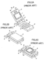
- FIGS. 2A-2C show a foldable portable telephone described in the above publication No. 11-30226.
- FIG. 2A is a perspective view in an opened state
- FIG. 2B is a perspective view that shows a usual folded state
- FIG. 2C is a perspective view that shows a reversed folded state.
- reference numerals and symbols corresponding to those used in this publication are attached with a prime symbol "'".
- a pivot 6' that makes it possible to reverse the front and back of a casing 2' at the display section is provided at a right angle to an axis portion 5a' of a hinge 5' that connects the casing 2' at the display section side with a casing 4' at the operation section side.
- This publication also discloses a structure that the pivot 6' is provided with a rotation limiting mechanism that limits the rotation at a front and back reversing position, and a click stopping mechanism that holds a rotation limited state.
- Japanese Patent Application Laid-open Publication No. 11-215218 also discloses a "portable radio communication apparatus" that tries to solve a similar problem.
- FIGS. 3A-3C show a portable radio communication apparatus described in the above publication No. 11-215218.
- FIG. 3A is a perspective view in a state that a casing at a display side is rotated in an opened state
- FIG. 3B is a top plan view that shows a first posture that the apparatus is closed with the display set to the inside
- FIG. 3C is a top plan view that shows a second posture that the apparatus is closed with the display exposed to the outside.
- reference numerals and symbols corresponding to those used in this publication are attached with a prime symbol "'".
- a hinge section 5' structured with a ball joint for example, is used to connect a second casing (a casing at a display section) 6' provided with a display 7' to a first casing 1' that forms a pair with the second casing so that they can be freely opened and closed and supported to rotate relatively in an opened state.
- a portable radio communication apparatus 10' is allowed to be closed with the second casing 6' reversed.
- Japanese Patent Application Laid-open Publication No. 2000-353030 proposes an "open/close type portable information terminal" such as a portable telephone that makes it possible to look at a display or carry out a simple operation without setting the upper and lower units to an opened state.
- a display section casing having a display section and a operation section casing having a operation section are structured to be able to rotate freely by connecting respective one end of both casings with a rotation mechanism in a state that a display section surface faces the same direction as that of a operation section surface.
- Operation keys that make it possible to look at the display section in a closed state, and carry out an operation in a closed state are provided in the display section casing. With this arrangement, it is possible to carry out a simple operation in a closed state.
- a technique for solving the other problem that it is difficult to read sentences is disclosed in Japanese Patent Application Laid-open Publication No. 2001-156893.
- This technique is designed as a communication display system to be provided with a display unit section that can rotate a liquid display unit from vertically oriented to horizontally oriented and vice versa, and a display switching section that changes over a display of the liquid display section from vertically oriented to horizontally oriented and vice versa in synchronization with the rotation of the display unit section.
- a rotatable display unit section is fitted to a main body in the case of a bar-type portable telephone, and is fitted to an upper unit of a main body in the case of a foldable portable telephone.
- the rotatable display unit section is axially supported rotatably in a plane parallel with a main body surface.
- this publication also proposes a structure that a operation button is provided on a main body of the communication apparatus that appears after the display unit section has been rotated from vertical orientation to horizontal orientation.
- Japanese Patent Application Laid-open Publication No. 7-202748 discloses a portable radio apparatus having a display section that does not rotate but having a casing simply divided into two flat casings which overlap each other and connected rotatably along a plane parallel to the flat surface thereof, allowing the casings to be folded when not used, resulting in improved portability.
- Japanese Patent Application Laid-open Publication No. 5-211547 discloses a portable telephone also having a fixed display section, in which a casing having a transmitter is rotatably and axially supported relative to a main casing, and a connection surface of both casings is formed in a curve. With this arrangement, when opened, a receiver and the transmitter are in a distance and at an angle suitable for communications.
- the present invention has been made to solve the above problems in the conventional portable telephone.
- An object of the present invention is to provide a foldable portable information terminal that is a further improvement of the conventional foldable structure, to avoid the need of opening upper and lower units to see various displays and carry out corresponding operations, to display a large quantity of characters easy to read, and to improve display of various images, in a novel structure with improved operability compared to the conventional one.
- a foldable portable information terminal includes a first unit having a display section on its one side, a second unit having an operation section, and a movable connecting mechanism connecting the first unit and the second unit at one end thereof.
- the foldable portable information terminal is characterized in that the movable connecting mechanism allows the first unit to be opened, closed, and freely rotated with respect to a longitudinal direction of the second unit.
- the movable connecting mechanism may be a biaxial hinge, which connects the first unit to the second unit so that the first unit is allowed to be opened and closed and rotated freely.
- the biaxial hinge include: a first rotation axis which is securely and rotatably provided on an operation surface of the second unit in vicinity of one end thereof, the first rotation axis protruding approximately vertically from the operation surface; and a second rotation axis which is orthogonal to the first rotation axis and is provided in vicinity of a front end of the first rotation axis to axially and rotatably support the first unit.
- the movable connecting mechanism may be fixedly disposed at a position that is deviated from center of one end of the operation surface of the second unit.
- a part of the operation section on the second unit is exposed in a state that the first unit and the second unit are closed with the display section facing out, wherein a predetermined function is allocated to each key included in the part of the operation section.
- the foldable portable information terminal may further include: a first stopping mechanism for stopping the first unit and the second unit at a predetermined rotation position; and a second stopping mechanism for stopping the first unit and the second unit in a predetermined open and close state.
- the foldable portable information terminal may further include: a rotation energizing mechanism for energizing the first unit and the second unit from the vicinity of the predetermined rotation position to a stop state position; and an open and close energizing mechanism for energizing the first unit and the second unit from the vicinity of the predetermined open and close state position to a stop state position.
- the foldable portable information terminal may further include: a first restricting means for restricting a range of rotation of the first unit with respect to the second unit within a predetermined rotation angle range; and a second restricting means for restricting the first unit and the second unit within a predetermined open and close angle range.
- a rotation range of the first unit may be restricted within a rotation angle range from -180° to +180°.
- the first unit may further have a secondary display section on the other side thereof.
- the foldable portable information terminal may further include a position detector for determining an open and closed state and a rotation positional relationship of the first unit and the second unit.
- the position detector may include: a plurality of magnetic field generators which are each provided at predetermined positions within one of the first and second units; a plurality of magnetic field detectors which are each provided at predetermined positions within the other of the first and second units, corresponding to the magnetic field generators; and a position determining section for determining a position of the first unit based on a detection signal of the magnetic field detector, wherein the detection signal varies depending on a positional relationship between the first unit and the second unit.
- the foldable portable information terminal may further include a display controller controlling the display section of an approximately rectangular shape such that a displaying mode of the display section is changed depending on a positional relationship between the first unit and the second unit.
- the display controller may change a direction of displayed contents on the display section so that the direction of the displayed contents matches a longitudinal direction of the second unit independently of a longitudinal direction of the display section which is one of a parallel direction and an orthogonal direction with respect to the longitudinal direction of the second unit.
- the display controller may change a direction of displayed contents on the display section so that the direction of the displayed contents matches a position of the second unit in a state that the first unit and the second unit are closed with the display section facing out.
- the first unit may have a second operation section which faces out when the first unit and the second unit are closed with the display section facing out so that the second operation section be used to perform a menu operation, an image operation, and a call arrival operation while visually confirming displayed contents on the display section.
- the second operation section may be a touch panel provided on the display surface of the display section.
- the foldable portable information terminal may further include a touch panel function controller for changing a touch panel function enabled area of the touch panel on the display surface depending on a positional relationship between the first unit and the second unit.
- the second operation section may include at least one operation button provided on a side surface of the first unit.
- a directional operation performed by using the operation section may be changed depending on a positional relationship between the first unit and the second unit.
- a direction instructed by a direction indication key of the operation section may be changed depending on a positional relationship between the first unit and the second unit, which is one of an open state, a rotated state, and a closed state with the display section facing out.
- the display section may be stopped displaying and/or backlighting in a state that the first unit and the second unit are closed with the display section facing in.
- the foldable portable information terminal may further include: an alert device for generating an alert for at least a call arrival by using at least one of sound, vibration, light, and the display section; and an alert controller controlling the alert device such that, when the position detector detects that the first unit and the second unit are shifted to a normal conversation position in a state that the alert device is alerting for the call arrival, the alert controller stops the alert device alerting.
- the foldable portable information terminal may further include a call arrival and termination controller controlling such that the foldable portable information terminal is made off-hook when the position detector detects that the first unit and the second unit are shifted to a normal conversation position at an occurrence of an incoming call, and on-hook when the position detector detects that the first unit and the second unit are shifted from the normal conversation position to another position after the call has been terminated.
- a call arrival and termination controller controlling such that the foldable portable information terminal is made off-hook when the position detector detects that the first unit and the second unit are shifted to a normal conversation position at an occurrence of an incoming call, and on-hook when the position detector detects that the first unit and the second unit are shifted from the normal conversation position to another position after the call has been terminated.
- the foldable portable information terminal can be folded and freely rotated with respect to a longitudinal direction of the second unit, so that it can be folded with the display section facing out. Therefore, without opening the terminal, the user can read a mail, look at a map or other image, or confirm a calling party on the display. Consequently, the user can immediately carry out the operation of receiving a call after judging the display contents in the closed state.
- the terminal is folded with the display section facing out, it is possible to carry it in compact while looking at a map or the like on the screen, resulting in improved ease of use.
- the first unit having the display section can be rotated in a display plane direction, it is possible to suitably display the contents of both vertically and horizontally orientations without increasing in size, that is, the same size as a conventional portable telephone.
- a structure in which the connecting member occupies only at the center or in the vicinity of the center on the end section of the terminal increases the degree of freedom in designing, allowing the design of an unprecedented shape.
- a portable information terminal such as a portable telephone having an upper unit and a lower unit such that a unit having a display section (hereinafter, an upper unit) and a unit having a operation section (hereinafter, a lower unit) are connected to be able to be freely opened and closed
- a movable connecting member such as a biaxial hinge
- a hinge section a movable connecting member that connects both units to each other.
- the movable connecting member may be provided at the center position of the end portion of the upper unit and the lower unit, or may be provided at a position deviated from the center position.
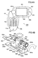
- FIG. 4A shows a state that the upper unit is extended to a horizontal orientation by facing the display surface outward.
- FIG. 4B shows a structure of the vicinity of a biaxial hinge (movable connecting member) 300 used in the present embodiment.
- a portable telephone 500 is composed mainly of three portions: a lower unit 100 that has a operation section; an upper unit 200 that has a display section; and the biaxial hinge 300 as a movable connecting member (a universal hinge section) that connects the lower unit 100 and the upper unit 200 allowing free rotation.
- the lower unit 100 and the upper unit 200 have flat and oval shapes having predetermined thickness and the approximately same size.
- the lower unit 100 and the upper unit 200 are mechanically connected via the biaxial hinge 300, which will be described in detail later.
- the upper unit 200 can rotate freely relative to the lower unit 100 around the biaxial hinge.
- the lower unit 100 and the upper unit 200 are electrically connected by an appropriate connection means via the biaxial hinge section.
- An external case 101 of the lower unit 100 accommodates various electronic circuits encircled with a broken line 100A of FIG. 6. Each of the circuits will be described later.
- An operation section is disposed on one surface (the operation surface) 101a of the lower unit 100 and is composed of a plurality of operation keys 102 to be used to perform functions of the portable telephone 500. Further, an opening section for a microphone 103 is disposed at the front end of the same operation surface.
- a first rotation axis 301 to be described later is rotatably fixed in a direction approximately perpendicular to the operation surface at the end portion of the lower unit and the center position in a width direction thereof with a predetermined distance (a distance of approximately a half of the thickness of the upper unit) from the edge of the lower unit in the vicinity of the base of the operation surface.
- An external case 201 of the upper unit 200 accommodates various electronic circuits encircled with a broken line 200A in FIG. 6. Each of the circuits will be described later.
- a display unit 202 having approximately a rectangular shape is disposed in vertical orientation on one surface (a display surface) of the upper unit.
- a speaker 203 is disposed at the front end.
- a small secondary display unit 206 is provided on the surface opposite to the display surface 201a (not shown in this figure).
- a second rotation axis 302 is rotatably fitted to a position at approximately the center in a thickness direction of the upper unit on the base (the connection side) of the upper unit.
- This second rotation axis 302 has its center rotatably connected to the end of the first rotation axis 301, and has brackets 303 and 303 fitted to both ends of the axis that extends to both sides.
- the brackets 303 and 303 are securely fixed to the upper unit 200 from the inside.
- the portable telephone 500 has such a structure that the two upper and lower units 200 and 100 are connected together with the biaxial hinge 300 that is structured to include the two orthogonal rotation axes 301 and 302 that can rotate independently, at the respective bases of the units.
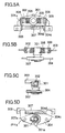
- This biaxial hinge 300 is structured to include a first rotation axis (hereinafter, a horizontal rotation axis) 301 made of metal that is accommodated within the lower unit 100, rotatably fixed to a base plate 304 made of metal, which is in turn fixed to the lower unit 100 from the inside, with its end protruding perpendicularly from the lower unit operation surface, and a second rotation axis (hereinafter, an open/close rotation axis) 302 made of metal that is horizontal (parallel with the lower unit), and pierces through the end portion of the horizontal rotation axis 301 at a right angle relative to the horizontal rotation axis 301, and is fixed rotatably.
- a first rotation axis hereinafter, a horizontal rotation axis
- base plate 304 made of metal
- the open/close rotation axis 302 has a coiled click plate spring 305 and a ring-shaped click plate 306 made of metal loosely and windingly engaged with each of axis portions extended to both sides thereof.
- a bracket 303 of an L-shaped metal plate is fixed to the front end of the extended axis portion at one end 303a thereof.
- the other end 303b of each bracket 303 is a fitting wing 303c that has its L-shaped leg bent at a right angle, which appears to extend horizontally in the drawing.
- the end of the horizontal rotation axis 301, the open/close rotation axis 302, and the brackets 303, 303 are accommodated in the upper unit 200.
- Fitting holes 303d provided on the fitting wing 303c are used to fix the brackets 303, 303 to the upper unit 200 from the inside.
- the horizontal rotation axis 301 and the open/close rotation axis 302 can rotate independently within a limited range.
- a restricting means (a stopper) is provided in each rotation axis mechanism so that a horizontal direction rotation range of the horizontal rotation axis 301 is restricted between -180° and +180°, and a rotation range of the open/close rotation axis 302 is restricted between 0° and 180°.
- a horizontal rotation axis restricting means (a stopper) restricts a horizontal rotation. The open and close rotation is restricted by butting a click mechanism against the external cases.
- the horizontal rotation axis restricting means will be described.
- the base plate 304 is in approximately a rectangular shape, and one long side 304a is matched with a curve shape of a connection side end of the external case of the lower unit.
- a long guide hole 304c of a predetermined width and a predetermined length is formed at the center of the other long side with a constant distance from the other long side 304b of the base plate 304.
- the center portion of the long side 304b corresponding to the long guide hole 304c is cut away by a constant width.
- Such a structure forms a guide bar 304d having a rectangular shape at its cross section in the long side 304b.
- a horizontal rotation angle restricting stopper piece 307 is wound around this guide bar 304d so as to be slidable within a predetermined distance.
- a stopping claw 307a (see FIG. 5D) is formed at the center of the lower side of the horizontal rotation angle restricting stopper piece 307 protruding towords the horizontal rotation axis 301 side.
- a projection 301a that is engaged with the stopping claw 307a is fitted to a lower end of the horizontal rotation axis 301, and this rotates together with the horizontal rotation axis 301.
- a horizontal direction rotation range (a rotation angle) of the upper unit is restricted.
- the rotation angle is restricted to ⁇ 180° (rotates by 180° in the clockwise direction and in the counterclockwise direction from a completely folded state). Therefore, it is structured such that the horizontal rotation angle restricting stopper piece 307 slides by the width of the projection 301a of the horizontal rotation axis stopper.
- Such an arrangement avoids the upper unit 200 excessively rotating by exceeding a folding position. It is preferable that a stopping mechanism is provided that holds the rotation angles with weak force corresponding to the normal communication position, the folding position, and intermediate positions between both positions (rotation angles +90° and -90°).
- the click mechanism is a mechanism that generates a suction torque to an opened state and a closed state (a torque to suck to an open position and a close position near the open position and the close position), and generates a holding torque at these positions.
- the click mechanism of the present embodiment is structured by the click plate 306 having a click plate projection 306a, a bracket groove 308, and the click plate spring 305.
- the click plate 306 has the click plate projection 306a extending to the bracket side (outwardly).
- Each of the brackets 303, 303 has the bracket groove 308 formed on its inside surface so as to be engaged with the click plate projection 306a when the bracket is at a predetermined rotation position.
- the bracket groove 308 is provided at positions (angles, for example, 160° and 180°) at which a click is generated at the close position and open position.
- the click plate spring 305 presses the click plate 306 against the bracket 303. This pressing force defines the click torque. In the drawing, it appears that the click plate spring 305 is separated from the click plate 306 because the drawing is partly omitted. However, actually, the spring 305 is mounted in a compressed state between the click plate 306 and the horizontal rotation axis 301 to energize the click plate 306 outwardly at all times. A click is generated when the click plate projection 306a drops into the bracket groove 308 at predetermined open and close positions. When the click plate projection 306a is not at a click generation position, an open and closed state (an extension angle) is held with weak force, based on frictional force between the click plate 306 and the bracket 303.
- the upper unit and the lower unit can be electrically connected using a known method.
- both units may be electrically connected by hollowing both the horizontal rotation axis and the open/close rotation axis and passing interconnection wires through the hollows.
- an FPC flexible print circuit
- an FPC flexible print circuit
- the open/close rotation axis is rotatable relative to the horizontal rotation axis.
- structure such that the open/close rotation axis and the horizontal rotation axis are firmly fixed, and a bracket is rotatably fixed to each of both ends of the horizontal axis.
- This biaxial hinge structure can provide a second rotation axis acting as the open/close rotation axis composed of the axis portion and the bracket constitute. Such a structure is also included in the concept of the biaxial hinge in the present invention.
- the portable telephone is structured to include an antenna 104, an RF circuit 105, a modem 106, a baseband processing circuit 107, a codec circuit 108, a control unit 109, a microphone 103, operation keys 102, a alert means 110, and three magnetic sensors 111a, 111b and 111c that detect a position of the upper unit (a posture relative to the lower unit).
- These functional sections are mounted within the lower unit 100.
- a means for detecting a position of the upper unit (a posture relative to the lower unit) is not restricted to the magnetic sensors (Hall elements) . It is also possible to use a reed switch or a known mechanical switch, for example.
- the control unit 109 includes a rotation angle detector 112 that decides a rotation angle of the upper unit 200 based on the output of each magnetic sensor 111, an open/close detector 113 that detects an open/close state including a front/back state, a display controller 114 that controls a direction of display contents so as to reflect outputs of the rotation angle detector 112 and the open/close detector 113, a call arrival and termination controller 115 that can carry out a call arrival control operation corresponding to the open/close and movement operation of the upper unit, and an alert controller 116 that can control a call arrival notification corresponding to the open/close and movement operation of the upper unit.
- the RF circuit 105 has a receiving circuit, a transmitting circuit, and a frequency synthesizer, which are not shown.
- the operation keys 102 includes a transmission key, conversion keys for alphabet/Kana/Kanji/numeral, a power source on/off key, a cross key for cursor operation, and an end key.
- the portable telephone of the embodiment is structured to include a speaker 203, a magnet 204a corresponding to the magnetic sensors 111a and 111b, a magnet 204c corresponding to the magnetic sensor 111c, a display unit (a liquid crystal display: LCD) 202 that becomes a main screen, and a touch panel mechanism 205, a secondary display unit 206, and a secondary operation key 207, which are built in the surface of the display unit 202. These functional sections are mounted on the upper unit.
- the speaker 203 acts as a telephone receiver and also as an alert means 110.
- the upper unit 200 can be opened and closed relative to the lower unit by rotating around the second rotation axis 302, and can rotate around the first rotation axis 301 relative to the lower unit 100. Therefore, although front and back surface direction of the upper unit 200 is limited to a direction parallel with the second rotation axis 302, the upper unit can pivot around the position of the first rotation axis to an arbitrary position on one surface side of the lower unit. Further, it is also possible to turn upside down on the same position. In other words, the lower unit 100 and the upper unit 200 can take various relative postures as demanded. At one of the predetermined stop positions, it is possible to hold a relative posture with the horizontal rotation axis restricting means and the click mechanism.
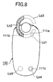
- the magnetic sensors 111a, 111b and 111c and the magnets 204 cooperate to detect a relative position between the lower unit 100 and the upper unit 200. Installation positions of the magnetic sensors 111 and the magnets 204 will be described in detail.
- three Hall elements (magnetic sensors) 111 are disposed inside the lower unit 100 with the sensitive sides of the sensors facing the operation surface side.
- the two Hall elements 111a and 111b are disposed on the circumference of a predetermined radius around the horizontal rotation axis 301 and on two radius lines that each form an angle of 45° with respect to a long axis of the lower unit to form a central angle of 90° in the drawing.
- the third Hall element 111c is disposed at a position shifting to one side in the front end of the lower unit.
- the magnet 204a that has a semicircle shape and is magnetized in a thickness direction in the drawing is fitted along the circumference of the predetermined radius around the first rotation axis 301 inside the upper unit 200. Further, the magnet 204b is provided at a position corresponding to the Hall element 111c in the front end of the upper unit.
- the magnetic sensors 111 may be disposed on the upper unit 200, and the magnets 204 may be disposed on the lower unit 100. It is essential that one of the magnetic sensor and the magnet forming a pair is disposed on the upper unit and the other is disposed on the lower unit. It is not always necessary to use a semicircle magnet, and separate magnets may be disposed at corresponding positions of the Hall elements 111a and 111b.
- Lo1 indicates a position of the magnet 204a and Lo4 indicates a position of the magnet 204b in the case where both units are folded with the display surface exposed to the outside.
- the respective Hall elements 111a, 111b, and 111c generate outputs and therefore a current state (position) of the upper unit can be determined based on the outputs from the rotation angle detector 112 and the open/close detector 113.
- Lo2 indicates a position of the magnet 204a when rotated by 90° in a clockwise direction in the drawing.
- the Hall element 111b generates an output and thereby a state (position) of the upper unit can be determined.
- Lo3 indicates a position of the magnet 204a when further rotated by 90° in the clockwise direction in the drawing (a normal communication position). In this case, no output is obtained from any one the Hall elements. Therefore, it is possible to decide a state (position) of the upper unit.
- the position of the magnet 204a also becomes Lo1 (the direction of the magnetic field becomes opposite in case of FIG.8).
- the position of the magnet 204c becomes Lo4' which does not coincide with the Hall element 111c, it is possible to determine that both units are in the folded state with the display surface facing inside.
- the Hall element also detects a direction of the magnetic field of the magnet, it is possible to decide various kinds of position without providing the Hall element 111c and the magnet 204b, and it is possible to detect a finer difference in position.
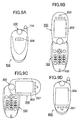
- the lower unit and the upper unit can take various mutual positions (relative postures) as demanded. Particularly, at stop positions as shown in FIGS. 9A-9D, it is possible to hold the relative position.
- the portable telephone is folded as the conventional case, which is compact and convenient to carry. Further, the display surface is protected without being exposed to outside.
- the secondary display section 206 provides a minimum display for information.
- FIG. 9B shows a state (a normal communication state) that the upper unit 200 is erected and extended from the state of FIG. 9A. In this state, confirmation of the display, various kinds of operation, and communications can be performed in a similar manner to that of the conventional portable telephone.
- FIG. 9C shows a state that the upper unit 200 is rotated by approximately 90 degrees in the clockwise direction from the state shown in FIG. 9B, for example, along a plane parallel with the operation surface 101a of the lower unit 100. At this time, the display section is horizontally oriented. The state of FIG. 9C is also obtained when the upper unit is rotated in the counterclockwise direction by sliding it from the folded state of FIG. 9D.
- this positional relationship is detected by the above-described position detecting means, which causes the display controller 114 to convert the display contents to be displayed on the display unit 202 into a horizontally oriented display (the left and right direction of the display contents matches the long side direction of the display unit).
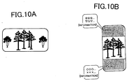
- FIG. 10A shows a display example (an image) of the display unit 202 in a state that the horizontally oriented contents information is displayed on the horizontally oriented screen. As shown in FIG. 10A, the whole display image of the horizontally long contents is displayed on the horizontally oriented screen.
- the vertically oriented contents can be displayed as it is in the vertically oriented position of the display section as shown in FIGS. 9B and 9D, and further it is also possible to display the center portion of a horizontally oriented image together with additional information by a predetermined operation or setting.
- FIG. 10B shows another display example of the display unit 202 that horizontally long contents information is displayed on the vertically oriented display screen as shown in FIGS. 9B and 9D.
- both units can take the above-described various positions
- the direction-included operation by a key such as a direction instructing key (cursor key) matches the display direction corresponding to each of the above-described various positions.
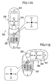
- a "direction key" in the operation keys 102 of the lower unit 100 is used to move a cursor or select a menu item.
- the "direction key” corresponding to one of directions D1-D4 is depressed, a processing in a corresponding one of directions D1'-D4' is carried out on the display screen.
- a move direction by the operation key 102 (the direction key) is changed so as to match the top, bottom, left and right of the display unit 202 of the upper unit 200 as shown in FIG. 11B.
- the processing in a corresponding one of directions D1'' to D4'' that are different from the above directions is carried out on the horizontally oriented display screen.
- the operation instructed by an operation key is suitably changed depending on the changeover between vertical and horizontal orientations of the display unit.
- the portable telephone of the embodiment it is possible to look at the display by rotating the display unit to a desired direction in the opened state, and carry out a desired operation.
- the upper unit 200 and the lower unit 100 also become in an approximately orthogonal state within approximately the same plane, and the display unit becomes horizontally oriented with respect to the top and bottom directions of the operation surface.
- such a positional relation of the upper unit and the lower unit can be detected by the above-described position detecting means, which causes the display controller 114 to convert the display contents to be displayed on the display unit 202 to a horizontally oriented display, that is, the left and right direction of the display contents matches the long side direction of the display unit, which is an opposite direction to the direction shown in FIG. 9C. Further, the processing instructed by a predetermined operation key is appropriately changed as described before.
- the portable telephone it is also possible to set the upper and lower units to a closed state such that the display unit faces out, which is opposite to the usual state that the display unit is accommodated inside when closed.
- the upper unit 200 is folded to the lower unit 100 with the display surface of the upper unit 200 facing out.
- the portable telephone becomes compact and becomes convenient for carrying it.
- the second operation section 207 since the second operation section 207 is exposed to the outside, it is possible to carry out a desired operation in response to the display contents by using the second operation section 207.
- Such a folded state as shown in FIG. 9D is detected by the above-described upper unit position detecting means, which causes the display contents on the display unit to turn upside down.
- the direction-included operation by a key such as a direction instructing key (cursor key) matches the display direction.
- the antenna 104 receives a radio signal from a base station, and transmits a radio signal.
- a radio signal received by the antenna 104 is output to a receiving circuit of the RF circuit 105.
- the receiving circuit selects a signal of a frequency indicated by a frequency synthesizer, and determines whether the selected signal includes a signal notifying of an incoming call to its own terminal (standby reception).
- the receiving circuit When the receiving circuit has detected a signal that notifies a call arrival to the own terminal, the receiving circuit notifies the call arrival to the control unit 109.
- the control unit 109 receives the notification from the receiving circuit that there is a call arrival to the own terminal, and drives the alert means 110 such as a beeper, a vibrator and/or a light-emitting diode to notify the user by sound, vibration and/or light blinking of the occurrence of an incoming call to the own terminal.
- the alert means 110 such as a beeper, a vibrator and/or a light-emitting diode to notify the user by sound, vibration and/or light blinking of the occurrence of an incoming call to the own terminal.
- a user can set the portable telephone to a mode such that, when it is detected that the upper unit and the lower unit are opened in a normal communication position, the call arrival and termination controller 115 automatically sets the operation to an off-hook state to connect the telephone line.
- the reception signal transmitted from a call originating terminal is output to the modem (modem) 106 via the RF circuit 105.
- the call arrival and termination controller 115 stops the alert operation.
- the modem 106 demodulates the reception signal to produce a baseband reception signal and output it to the baseband processing circuit 107.
- the baseband processing circuit 107 processes the baseband reception signal and outputs it to the codec circuit 108.
- the codec circuit 108 decodes the baseband reception signal to output a sound signal to the speaker (telephone receiver) 203, which outputs sound waves.
- the codec circuit 108 also encodes a sound signal received by the microphone 103 to output a transmission signal to the baseband processing circuit 107 and the transmission signal is transmitted to the destination through the modem 106 and the RF circuit 105. With this arrangement, the user can carry out communications immediately after the upper and lower units are opened.
- the telephone line is connected upon the off-hook operation of the user with a communication start key to allow communication.
- the unit position detector detects this position change, and the call arrival and termination controller automatically sets the operation state to the on-hook state (communication termination processing).
- the same communication termination can be made by the user operating a predetermined termination key for off-hook in the normal communication position.
- the portable telephone monitors whether the selected signal includes a signal indicating transmission of character data to its own terminal (standby reception).
- the control unit 109 automatically receives the transmitted character data without waiting for the off-hook operation, and displays information in the display unit 202 based on the received data.
- the alert controller 116 drives the alert means 110 such as a beeper or a vibrator in a predetermined fashion different from that at the occurrence of an incoming call to notify the user that character data or graphics data has been received.
- a signal carrying character data received from the call originating terminal is output to the modem 106 via the RF circuit 105, and is demodulated by the modem 106.
- the demodulated signal enters the baseband processing circuit 107, which extracts character data from the demodulated signal, to output it to the control unit 109.
- the control unit 109 includes the a CPU, a ROM storing programs, data necessary to process various kinds of processing, and character font data, a RAM used as a work area, a Video RAM to display information on the display unit 202, and the display controller 114 that controls the display unit 202 and/or the secondary display 206.
- the display controller 114 forms character information or graphic information to be displayed on the display unit 202 (or the secondary display unit 206 if necessary) based on data received from the baseband processing circuit 107.
- the portable telephone can create message data and transmit it to a destination.
- alphabet letters and Katakana characters are allocated to dial operation keys such as 0 to 9, *, and # that are provided on the operation section 102, and these keys include a conversion key for alphabet/Kana/Kanji/numeral conversion. It is possible to input message data and transmit it to a destination designated by the user operating these dial operation keys and the conversion key.
- the display unit 202 when character data or graphics data is transmitted or received, the display unit 202 can be rotated to set the display to be horizontally long or horizontally oriented, making it easy to read displayed information, compared with the case of a vertically oriented screen.
- the display unit 202 When character data or graphics data has been received, it is possible to use the display unit 202 as a horizontally oriented display unit as shown in FIG. 9C if the user wishes.
- the display controller 114 displays the display contents on the display unit 202 by converting the contents so as to match the direction of the horizontally oriented screen.
- the upper unit 202 may be fixed to be reversed left to right, which is opposite to that in FIG. 9C.
- the display controller 114 also displays the contents on the display unit 202 by converting the contents to match the direction of the horizontally oriented screen. Further, the processing instructed by a predetermined operation key is appropriately changed as described before.
- this portable telephone it is possible to transmit and receive character data or graphics data in the state that the upper unit and the lower unit are folded with the display unit 202 facing out.
- the user in the folded state with the display unit 202 facing out, the user can see the display unit 202 as it is.
- the secondary operation keys 207 are also exposed to the external surface, when character data or graphics data has been received, it is possible to confirm the display instantly, and it is also possible to carry out a simple response operation in a state that the portable telephone is closed.
- the display controller 114 displays the display contents on the display unit 202 by converting the contents to match the direction of the display screen that is reversed, the user can look at the display and carry out a response operation in the manner that the user is used to holding the terminal in the hand.
- the portable telephone according to the present embodiment can provide the following advantages.
- a conventional foldable portable telephone that is commercially available cannot see the main display without opening it.
- the portable telephone can be folded with the display section facing out. Therefore, without opening the portable telephone, the user can read a mail, look at a map or other image, or confirm a calling party on the display. Consequently, the user can immediately carry out the operation of receiving a telephone call after judging the display contents in the closed state.
- the portable telephone is folded with the display section facing out, it is possible to carry it in compact while looking at a map or the like on the screen.
- the portable telephone is folded with the display section facing in as in the conventional case, it is possible to carry the portable telephone with protecting the display section. Further, by rotating the display unit to vertical orientation, it is possible to display the contents in a desired one of vertically oriented and horizontally oriented states with one portable telephone having the same size as the conventional one.
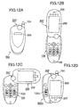
- FIGS. 12A-12D show different positions of of a portable information terminal according to the second embodiment of the present invention.
- the portable telephone 500A according to the present embodiment is also composed mainly of three portions including a lower unit 100 that has an operation section, an upper unit 200 that has a display section, and a biaxial hinge 300' as a movable connecting member that connects the lower unit 100 and the upper unit 200 so as to be freely rotatable.
- the present embodiment is characterized in that the biaxial hinge (movable connecting member) 300' is located at a position deviated from the center position at the end of the upper unit and the lower unit.
- the other members and their structure are similar to those of the first embodiment, and therefore, their descriptions will be omitted.
- members similar to those of the first embodiment are denoted by the same reference numerals or symbols.
- FIG. 12A shows a state that the units are folded with the display surface of the upper unit 200 facing the lower unit 100.
- FIG. 12B shows a state (a normal communication state) that the upper unit 200 is erected and extended from the state of FIG. 12A.
- FIG. 12C shows a state that the upper unit 200 is rotated by approximately 90 degrees in the clockwise direction from the state shown in FIG. 12B, for example, along a plane parallel with the operation surface 101a of the lower unit 100.
- FIG. 12D shows a state that the upper unit 200 is folded to the lower unit 100 with the display surface of the upper unit 200 facing out.
- the biaxial hinge (movable connecting member) 300' is located at a position deviated from the center position on the end of the upper unit and the lower unit. Therefore, particularly as shown in FIG. 12D, a part of operation keys 102, which is denoted by reference symbol 102b, is exposed in a state that the upper unit 200 is folded to the lower unit 100 with the display surface of the upper unit 200 facing out. In this state, the exposed part 102b of the operation keys 102 can be operated to which a predetermined key function is allocated. It is possible to suitably carry out a desired operation with the exposed part of the operation key 102a, thereby to improve the operability of the portable information terminal. In this structure, the secondary operation key 207 may be omitted.
- FIGS. 13A-13D show different positions of a portable information terminal according to a third embodiment of the present invention.
- a portable telephone 500B according to the present embodiment has a main structure similar to that of the first embodiment and therefore has similar appearance and mechanics.
- members similar to those of the first embodiment are denoted by the same reference numerals or symbols and their descriptions will be omitted.
- the present embodiment is characterized by control of a touch panel function.
- FIG. 13A shows a state that the units are folded with the display surface of the upper unit 200 facing the lower unit 100.
- FIG. 13B shows a state (a normal communication state) that the upper unit 200 is erected and extended from the state of FIG. 13A.
- FIG. 13C shows a state that the upper unit 200 is rotated by approximately 90 degrees in the clockwise direction from the state shown in FIG. 13B, for example, along a plane parallel with the operation surface 101a of the lower unit 100.
- FIG. 13D shows a state that the upper unit 200 is folded to the lower unit 100 with the display surface of the upper unit 200 facing out.
- a shaded area of the display section 202 in each of FIGS 13B-13D shows an example of a touch panel function enabled area 202t.
- the control unit 109 is further provided with a touch panel controller 208, which performs a touch panel control such that the touch panel function of the display unit 202 is made active or inactive.
- the touch panel controller 208 changes a touch panel function enabled area 202t of the display unit 202 depending on which one of a plurality of positions of the upper unit 200 and the lower unit 100 is currently taken.
- the touch panel controller 208 switches each portion of the full screen of the display unit 202 between active and inactive depending on a position of the upper unit 200 and the lower unit 100, which is one of a plurality of predetermined stop positions.
- the control unit 109 is provided with a memory (RAM) that previously stores the settings of a touch panel function enabled area 202t of the display unit 202, each settings corresponding to an opened state, a display horizontal-orientation state, and a closed state (display facing out) of the stop position between the upper unit 200 and the lower unit 100.
- RAM memory
- the shaded lower portion of the display section in the vertically oriented display state is set to a touch panel function enabled area 202t.
- the shaded lower portion of the horizontally oriented display section is set to a touch panel function enabled area 202t.
- the full screen of the display section is set to a touch panel function enabled area 202t.
- the control unit 109 monitors sensor outputs of the magnetic sensors to detect a current position of the upper and lower units: open, close or rotation positions (step S101).
- a current position of the upper and lower units open, close or rotation positions
- step S101 When the current position has been detected (YES at step S101), it is determined whether the detected position is a stop position (1.) (step S102).
- step S102 When it is the stop position (1.) (YES at step S102), a touch panel enabled area is changed to the lower portion in the vertically oriented display state (step S104).
- it is determined whether the detected position is a stop position (2.) (step S103).
- a touch panel enabled area is changed to the lower portion in the horizontally oriented display state (step S105).
- a touch panel enabled area is set to the full screen of the display section (step S106).
- the touch panel enabled area 202t of the display unit 202 is changed between the lower portion and the full screen of the display section depending on which one of the plurality of stop positions is detected.
- the enabled area may be expressed as a number of rows in a predetermined character size display, instead of a zone (area) of the display section.
- the settings stored in the memory (RAM) may be arbitrarily determined by a user.
- the hinge section (movable connecting member) may be designed in a structure different from the above-described embodiments. It is essential that the connecting member can connect the upper unit to the lower unit so that the upper unit can be freely rotated, opened and closed to allow a desired relative position thereof as described above.
- Other members may be modified within the technical scope of the present invention.
- the display unit is not limited to an LCD, and may use an electro luminescent (EL).
- operation buttons may be provided on the side surface of the upper unit as a secondary operation section.
- the present invention has been explained taking a portable telephone as embodiments, the present invention is not limited to the portable telephone. It is also possible to apply the present invention to a portable information terminal such as a PDA, provided that the operation section and the display section are separated and foldable, which can achieve similar operations and effects as described above.
- a portable information terminal such as a PDA
- the portable information terminal according to the present invention can provide the following advantages.
- a conventional foldable portable telephone that is commercially available cannot see the main display without opening it.
- the portable telephone can be folded and freely rotated with respect to a longitudinal direction of the lower unit, so that it can be folded with the display section facing out. Therefore, without opening the portable telephone, the user can read a mail, look at a map or other image, or confirm a calling party on the display. Consequently, the user can immediately carry out the operation of receiving a telephone call after judging the display contents in the closed state.
- the portable telephone is folded with the display section facing out, it is possible to carry it in compact while looking at a map or the like on the screen, resulting in improved ease of use.
- the upper unit having the display section can be rotated in a display plane direction, it is possible to suitably display the contents of both vertically and horizontally orientations without increasing in size, that is, the same size as the conventional portable telephone.
- connection section occupies only the center portion increases the degree of freedom in designing, allowing the design of an unprecedented shape.
Landscapes
- Engineering & Computer Science (AREA)
- Signal Processing (AREA)
- Telephone Set Structure (AREA)
- Pivots And Pivotal Connections (AREA)
- Casings For Electric Apparatus (AREA)
- Telephone Function (AREA)
- Mobile Radio Communication Systems (AREA)
Abstract
Description
Claims (23)
- A foldable portable information terminal comprising:characterized in that the movable connecting mechanism allows the first unit to be opened, closed, and freely rotated with respect to a longitudinal direction of the second unit.a first unit (200) having a display section (202) on its one side;a second unit (100) having an operation section (102); anda movable connecting mechanism (300) connecting the first unit and the second unit at one end thereof,
- The foldable portable information terminal according to claim 1, wherein the movable connecting mechanism is a biaxial hinge which connects the first unit to the second unit so that the first unit is allowed to be opened and closed and rotated freely,
wherein the biaxial hinge comprises:a first rotation axis (301) which is securely and rotatably provided on an operation surface of the second unit in vicinity of one end thereof, the first rotation axis protruding approximately vertically from the operation surface; anda second rotation axis (302) which is orthogonal to the first rotation axis and is provided in vicinity of a front end of the first rotation axis to axially and rotatably support the first unit. - The foldable portable information terminal according to claim 1 or 2, wherein the movable connecting mechanism is fixedly disposed at a position that is deviated from center of one end of the operation surface of the second unit.
- The foldable portable information terminal according to claim 1, further comprising:a first stopping mechanism for stopping the first unit and the second unit at a predetermined rotation position; anda second stopping mechanism for stopping the first unit and the second unit in a predetermined open and close state.
- The foldable portable information terminal according to claim 4, further comprising:a rotation energizing mechanism for energizing the first unit and the second unit from the vicinity of the predetermined rotation position to a stop state position; andan open and close energizing mechanism for energizing the first unit and the second unit from the vicinity of the predetermined open and close state position to a stop state position.
- The foldable portable information terminal according to claim 1, further comprising:a first restricting means for restricting a range of rotation of the first unit with respect to the second unit within a predetermined rotation angle range; anda second restricting means for restricting the first unit and the second unit within a predetermined open and close angle range.
- The foldable portable information terminal according to claim 6, wherein a rotation range of the first unit is restricted within a rotation angle range from -180° to +180°.
- The foldable portable information terminal according to claim 1, wherein the first unit further has a secondary display section on the other side thereof.
- The foldable portable information terminal according to claim 1, further comprising:a position detector (112, 113) for determining an open and closed state and a rotation positional relationship of the first unit and the second unit.
- The foldable portable information terminal according to claim 9, wherein the position detector comprises:a plurality of magnetic field generators (204a, 204b) which are each provided at predetermined positions within one of the first and second units;a plurality of magnetic field detectors (111a, 111b, 111c) which are each provided at predetermined positions within the other of the first and second units, corresponding to the magnetic field generators; anda position determining section for determining a position of the first unit based on detection signals of the magnetic field detectors, wherein each detection signal varies depending on a positional relationship between the first unit and the second unit.
- The foldable portable information terminal according to claim 9 or 10, further comprising:a display controller (114) controlling the display section of an approximately rectangular shape such that a displaying mode of the display section is changed depending on a positional relationship between the first unit and the second unit.
- The foldable portable information terminal according to claim 11, wherein the display controller changes a direction of displayed contents on the display section so that the direction of the displayed contents matches a longitudinal direction of the second unit independently of a longitudinal direction of the display section which is one of a parallel direction and an orthogonal direction with respect to the longitudinal direction of the second unit.
- The foldable portable information terminal according to claim 11, wherein the display controller changes a direction of displayed contents on the display section so that the direction of the displayed contents matches a position of the second unit in a state that the first unit and the second unit are closed with the display section facing out.
- The foldable portable information terminal according to claim 3, wherein a part of the operation section on the second unit is exposed in a state that the first unit and the second unit are closed with the display section facing out, wherein a predetermined function is allocated to each key included in the part of the operation section.
- The foldable portable information terminal according to claim 1, wherein the first unit has a second operation section which faces out when the first unit and the second unit are closed with the display section facing out so that the second operation section be used to perform a menu operation, an image operation, and a call arrival operation while visually confirming displayed contents on the display section.
- The foldable portable information terminal according to claim 15, wherein the second operation section is a touch panel provided on the display surface of the display section.
- The foldable portable information terminal according to claim 15 or 16, wherein the second operation section comprises at least one operation button provided on a side surface of the first unit.
- The foldable portable information terminal according to claim 1, wherein a directional operation performed by using the operation section is changed depending on a positional relationship between the first unit and the second unit.
- The foldable portable information terminal according to claim 18, wherein a direction instructed by a direction indication key of the operation section is changed depending on a positional relationship between the first unit and the second unit, which is one of an open state, a rotated state, and a closed state with the display section facing out.
- The foldable portable information terminal according to claim 16, further comprising:a touch panel function controller (208) for changing a touch panel function enabled area of the touch panel on the display surface depending on a positional relationship between the first unit and the second unit.
- The foldable portable information terminal according to claim 1, wherein the display section is stopped displaying and/or backlighting in a state that the first unit and the second unit are closed with the display section facing in.
- The foldable portable information terminal according to claim 9, further comprising:an alert device (110) for generating an alert for at least a call arrival by using at least one of sound, vibration, light, and the display section; andan alert controller (116) controlling the alert device such that, when the position detector detects that the first unit and the second unit are shifted to a normal conversation position in a state that the alert device is alerting for the call arrival, the alert controller stops the alert device alerting.
- The foldable portable information terminal according to claim 9, further comprising:a call arrival and termination controller (115) controlling such that the foldable portable information terminal is made off-hook when the position detector detects that the first unit and the second unit are shifted to a normal conversation position at an occurrence of an incoming call, and on-hook when the position detector detects that the first unit and the second unit are shifted from the normal conversation position to another position after the call has been terminated.
Applications Claiming Priority (4)
| Application Number | Priority Date | Filing Date | Title |
|---|---|---|---|
| JP2001303959 | 2001-09-28 | ||
| JP2001303959 | 2001-09-28 | ||
| JP2002189488A JP2003174495A (en) | 2001-09-28 | 2002-06-28 | Folding portable information terminal |
| JP2002189488 | 2002-06-28 |
Publications (3)
| Publication Number | Publication Date |
|---|---|
| EP1298890A2 true EP1298890A2 (en) | 2003-04-02 |
| EP1298890A3 EP1298890A3 (en) | 2004-04-28 |
| EP1298890B1 EP1298890B1 (en) | 2006-07-19 |
Family
ID=26623453
Family Applications (1)
| Application Number | Title | Priority Date | Filing Date |
|---|---|---|---|
| EP02021875A Expired - Lifetime EP1298890B1 (en) | 2001-09-28 | 2002-09-30 | Foldable portable information terminal |
Country Status (5)
| Country | Link |
|---|---|
| US (3) | US7499737B2 (en) |
| EP (1) | EP1298890B1 (en) |
| JP (3) | JP2003174495A (en) |
| CN (1) | CN1213585C (en) |
| DE (1) | DE60213178T2 (en) |
Cited By (22)
| Publication number | Priority date | Publication date | Assignee | Title |
|---|---|---|---|---|
| EP1467537A1 (en) * | 2003-04-07 | 2004-10-13 | Sony Ericsson Mobile Communications Japan, Inc. | Portable communication terminal device |
| EP1505478A1 (en) * | 2003-08-08 | 2005-02-09 | Sony Ericsson Mobile Communications AB | Navigation unit in hinge |
| EP1533983A1 (en) * | 2003-11-21 | 2005-05-25 | Lg Electronics Inc. | Mobile terminal having rotatable camera and swivel hinge structure |
| WO2005065145A2 (en) | 2003-12-23 | 2005-07-21 | Nokia Corporation | A communication device with rotating housing |
| WO2005069588A1 (en) | 2003-12-31 | 2005-07-28 | Sony Ericsson Mobile Communications Ab | Apparatus for mobile terminal display |
| WO2005015885A3 (en) * | 2003-08-08 | 2005-08-04 | Sony Ericsson Mobile Comm Ab | Navigation unit in hinge |
| EP1575248A1 (en) * | 2004-03-08 | 2005-09-14 | Nec Corporation | Portable and foldable information terminal |
| EP1610530A1 (en) * | 2004-06-21 | 2005-12-28 | Samsung Electronics Co., Ltd. | Dual-axis rotation folder-type portable apparatus |
| KR100547735B1 (en) * | 2003-06-16 | 2006-01-31 | 삼성전자주식회사 | Display device and method of mobile terminal |
| EP1699209A1 (en) * | 2005-03-02 | 2006-09-06 | Sharp Kabushiki Kaisha | Folding cellular phone with open/close restriction means |
| EP1783985A1 (en) | 2005-11-07 | 2007-05-09 | LG Electronics Inc. | Mobile terminal and method for changing screen mode thereof |
| EP1615408A3 (en) * | 2004-07-08 | 2007-05-23 | Sharp Kabushiki Kaisha | Foldable device with a 3d hinge having a displaced vertical axis |
| EP1898604A2 (en) | 2006-09-06 | 2008-03-12 | Sony Ericsson Mobile Communications Japan, Inc. | Portable terminal |
| WO2008058555A1 (en) * | 2006-11-14 | 2008-05-22 | Nokia Corporation | Swivel hinge mechanism and related device comprising a plurality of housing parts |
| EP1925904A1 (en) * | 2006-11-21 | 2008-05-28 | C.R.F. Società Consortile per Azioni | Method and device for determining the relative position of two elements that are mobile with respect to one another |
| RU2342801C2 (en) * | 2005-11-07 | 2008-12-27 | ЭлДжи ЭЛЕКТРОНИКС ИНК. | Mobile terminal and method of change of its mode |
| EP1517220A3 (en) * | 2003-09-19 | 2008-12-31 | Kabushiki Kaisha Toshiba | Information processing apparatus having function of changing orientation of screen image |
| US7486323B2 (en) | 2004-02-27 | 2009-02-03 | Samsung Electronics Co., Ltd. | Portable electronic device for changing menu display state according to rotating degree and method thereof |
| EP1865693A4 (en) * | 2005-03-30 | 2009-06-24 | Nec Corp | Portable information terminal device and function selection startup method used for the same |
| EP1473910A3 (en) * | 2003-04-30 | 2009-11-11 | NEC Corporation | Folding mobile communication apparatus |
| EP1980930A4 (en) * | 2006-01-30 | 2012-03-14 | Nec Corp | Mobile electronic apparatus |
| GB2535430B (en) * | 2014-11-24 | 2018-12-05 | New Dawn Innovations Ltd | An audio playing apparatus with a rotatable control console including a display |
Families Citing this family (195)
| Publication number | Priority date | Publication date | Assignee | Title |
|---|---|---|---|---|
| US6560468B1 (en) * | 1999-05-10 | 2003-05-06 | Peter V. Boesen | Cellular telephone, personal digital assistant, and pager unit with capability of short range radio frequency transmissions |
| US20030104791A1 (en) * | 2001-05-17 | 2003-06-05 | Engstrom G. Eric | Adding peripherals to mobile device via smart interchangeable cover |
| FI20015005A7 (en) * | 2001-05-31 | 2002-12-01 | Nokia Corp | Mobile device including display element |
| JP4063571B2 (en) * | 2002-04-10 | 2008-03-19 | 日本電気株式会社 | Foldable mobile communication terminal |
| CA102494S (en) * | 2002-09-20 | 2004-02-11 | Kyocera Corp | Cellular phone |
| JP3961397B2 (en) * | 2002-10-29 | 2007-08-22 | 京セラ株式会社 | Mobile terminal device |
| JP4125653B2 (en) * | 2002-10-30 | 2008-07-30 | 日本電気株式会社 | Portable information terminal device |
| WO2005081417A1 (en) * | 2004-02-23 | 2005-09-01 | Matsushita Electric Industrial Co., Ltd. | Portable wireless device |
| JP3920196B2 (en) | 2002-11-11 | 2007-05-30 | 松下電器産業株式会社 | Portable wireless device |
| JP4073296B2 (en) * | 2002-11-14 | 2008-04-09 | 京セラ株式会社 | Stackable mobile phone |
| JP2004172986A (en) * | 2002-11-20 | 2004-06-17 | Nec Access Technica Ltd | Portable terminal and its posture detection method |
| US7023421B2 (en) * | 2002-11-26 | 2006-04-04 | Motorola, Inc. | Subscriber device with adaptable user interface and method thereof |
| JP4238571B2 (en) * | 2002-12-06 | 2009-03-18 | 日本電気株式会社 | Foldable portable device, its wiring device and wiring method |
| US20040203520A1 (en) * | 2002-12-20 | 2004-10-14 | Tom Schirtzinger | Apparatus and method for application control in an electronic device |
| US7117009B2 (en) * | 2002-12-20 | 2006-10-03 | Motorola, Inc. | Apparatus and method for electronic device control |
| JP3796222B2 (en) * | 2003-01-08 | 2006-07-12 | 三洋電機株式会社 | Portable wireless terminal |
| JP4402355B2 (en) * | 2003-01-21 | 2010-01-20 | 京セラ株式会社 | Stackable mobile terminal device |
| KR100504144B1 (en) * | 2003-01-30 | 2005-07-27 | 삼성전자주식회사 | Method for sensing a position of folder in a rotation touchable phone having a camera |
| JP2004240878A (en) * | 2003-02-07 | 2004-08-26 | Nec Corp | Portable electronic appliance, display direction switching method and program |
| JP4018002B2 (en) * | 2003-02-24 | 2007-12-05 | 京セラ株式会社 | Mobile terminal device with camera |
| JP4150615B2 (en) * | 2003-03-10 | 2008-09-17 | 京セラ株式会社 | Hinge device |
| JP2004293633A (en) * | 2003-03-26 | 2004-10-21 | Nec Corp | Folding portable terminal |
| US20040198439A1 (en) * | 2003-04-01 | 2004-10-07 | Dong-Ryong Kim | Device and method for displaying pictures in a mobile terminal |
| JP2004312476A (en) * | 2003-04-09 | 2004-11-04 | Nec Corp | Foldable portable information terminal |
| JP4089487B2 (en) * | 2003-04-10 | 2008-05-28 | 松下電器産業株式会社 | Information equipment |
| JP2004328279A (en) * | 2003-04-23 | 2004-11-18 | Kato Electrical Mach Co Ltd | Portable terminal machine |
| US7856251B2 (en) | 2003-04-24 | 2010-12-21 | Samsung Electronics Co., Ltd. | Device and method for using a rotating key and controlling a display in a mobile terminal |
| JP4021797B2 (en) * | 2003-04-28 | 2007-12-12 | 京セラ株式会社 | Mobile terminal device |
| US7475452B2 (en) * | 2003-05-21 | 2009-01-13 | Premier Image Technology Corporation | Swivel structure for information product |
| USD524776S1 (en) * | 2003-05-26 | 2006-07-11 | Lg Electronics Inc. | Cellular phone |
| USD488453S1 (en) | 2003-06-02 | 2004-04-13 | Inventec Appliances Corporation | Mobile communication device |
| USD498734S1 (en) | 2003-07-23 | 2004-11-23 | Lg Electronics Inc. | Cellular phone |
| USD506452S1 (en) * | 2003-07-26 | 2005-06-21 | Lg Electronics Inc. | Cellular phone |
| CA105722S (en) * | 2003-07-31 | 2005-09-19 | Kyocera Corp | Portable telephone |
| US7450977B2 (en) * | 2003-07-31 | 2008-11-11 | Vodafone K.K. | Mobile communication terminal |
| US20050078211A1 (en) * | 2003-07-31 | 2005-04-14 | Symon Whitehorn | Handheld device with integral axial camera |
| JP2005078316A (en) | 2003-08-29 | 2005-03-24 | Kyocera Corp | Mobile terminal device |
| US7529571B2 (en) * | 2003-09-03 | 2009-05-05 | Samsung Electronics Co., Ltd. | Sliding/hinge apparatus for sliding/rotating type mobile terminals |
| US8155718B2 (en) * | 2003-09-03 | 2012-04-10 | Samsung Electronics Co., Ltd. | Sliding/hinge apparatus for sliding/rotating type mobile terminals |
| JP4791687B2 (en) * | 2003-09-05 | 2011-10-12 | 修司 北澤 | Input device |
| USD498737S1 (en) | 2003-09-26 | 2004-11-23 | Lg Electronics Inc. | Cellular phone |
| JP4905871B2 (en) * | 2003-09-30 | 2012-03-28 | 京セラ株式会社 | Information display device |
| JP4288134B2 (en) * | 2003-10-16 | 2009-07-01 | 京セラ株式会社 | Imaging device |
| WO2005039157A1 (en) * | 2003-10-22 | 2005-04-28 | Sanyo Electric Co., Ltd. | Mobile telephone apparatus, display method, and program |
| JP4113092B2 (en) * | 2003-10-24 | 2008-07-02 | 三菱製鋼株式会社 | Biaxial hinge rotation mechanism and mobile phone equipped with the same |
| KR100606108B1 (en) | 2003-10-31 | 2006-07-28 | 삼성전자주식회사 | Swing type portable digital communication terminal and swing hinge device thereof |
| JP4771655B2 (en) * | 2003-11-25 | 2011-09-14 | ソニー・エリクソン・モバイルコミュニケーションズ株式会社 | Portable electronic device, information processing method, program, and recording medium |
| USD503699S1 (en) * | 2003-12-01 | 2005-04-05 | Samsung Electronics Co., Ltd. | Cellular phone |
| USD502162S1 (en) * | 2003-12-02 | 2005-02-22 | Samsung Electronics Co., Ltd. | Cellular phone |
| USD539773S1 (en) * | 2003-12-11 | 2007-04-03 | Samsung Electronics Co. | Portable telephone |
| KR100608731B1 (en) | 2003-12-22 | 2006-08-04 | 엘지전자 주식회사 | Swivel handset and call method using same |
| US20050136998A1 (en) * | 2003-12-23 | 2005-06-23 | Spence Michael F. | Spring biased hinge and methods therefor |
| CA2535671A1 (en) * | 2004-01-16 | 2005-07-28 | Temco Japan Co., Ltd. | Portable telephone using bone conduction device |
| KR100631677B1 (en) * | 2004-02-11 | 2006-10-09 | 엘지전자 주식회사 | Handheld terminal with swivel type folder |
| JP4975240B2 (en) * | 2004-03-26 | 2012-07-11 | カシオ計算機株式会社 | Terminal device and program |
| US7747226B2 (en) | 2004-04-13 | 2010-06-29 | Sony Ericsson Mobile Communications Ab | Portable electronic devices including multi-mode matching circuits and methods of operating the same |
| US7339600B2 (en) * | 2004-04-26 | 2008-03-04 | Samsung Electronics Co., Ltd. | Apparatus and method for displaying a picture in a wireless terminal |
| USD503164S1 (en) * | 2004-05-05 | 2005-03-22 | Samsung Electronics Co., Ltd. | Portable telephone |
| US20060007139A1 (en) * | 2004-06-03 | 2006-01-12 | Ong Dee N | Device and method for configuring a user operated screen controller |
| TWM259413U (en) * | 2004-06-04 | 2005-03-11 | Fih Co Ltd | Mobile phone having a keyboard convenient for inputting |
| JP4616597B2 (en) | 2004-08-27 | 2011-01-19 | 富士通株式会社 | Electronic equipment |
| USD519971S1 (en) * | 2004-08-27 | 2006-05-02 | Kabushiki Kaisha Toshiba | Portable phone |
| JP4603317B2 (en) * | 2004-08-27 | 2010-12-22 | 富士通株式会社 | Electronic device and circuit board |
| JP4747537B2 (en) * | 2004-09-07 | 2011-08-17 | 日本電気株式会社 | Portable terminal, control method therefor, and computer program for portable terminal |
| USD526987S1 (en) * | 2004-09-23 | 2006-08-22 | Lg Electronics, Inc. | Cellular phone |
| US20060073807A1 (en) * | 2004-10-01 | 2006-04-06 | Baker Thomas W | Cellular pedometer |
| JP2006106613A (en) * | 2004-10-08 | 2006-04-20 | Toshiba Corp | Video display device |
| WO2006040726A1 (en) * | 2004-10-15 | 2006-04-20 | Koninklijke Philips Electronics N.V. | Method of operating a rfid system |
| JPWO2006046681A1 (en) * | 2004-10-25 | 2008-05-22 | 松下電器産業株式会社 | Mobile phone equipment |
| JP2006140571A (en) * | 2004-11-10 | 2006-06-01 | Matsushita Electric Ind Co Ltd | Foldable portable radio |
| KR100678162B1 (en) * | 2004-11-15 | 2007-02-02 | 삼성전자주식회사 | Sliding and Folding Portable Communication Device |
| USD519972S1 (en) * | 2004-11-16 | 2006-05-02 | Samsung Electronics Co., Ltd. | Cellular phone |
| JP4533098B2 (en) * | 2004-11-16 | 2010-08-25 | キヤノン株式会社 | Image display device, display control method for image display device, program, and storage medium |
| JP4522233B2 (en) * | 2004-11-17 | 2010-08-11 | パナソニック株式会社 | Mobile device |
| JP4498115B2 (en) * | 2004-12-09 | 2010-07-07 | 株式会社東芝 | Mobile terminal device |
| JP2006191438A (en) * | 2005-01-07 | 2006-07-20 | Matsushita Electric Ind Co Ltd | Mobile device |
| JP2006197420A (en) * | 2005-01-17 | 2006-07-27 | Sanyo Electric Co Ltd | Broadcast receiver |
| USD543169S1 (en) * | 2005-01-21 | 2007-05-22 | Samsung Electronics Co., Ltd. | Mobile phone |
| USD531974S1 (en) * | 2005-01-26 | 2006-11-14 | Samsung Electronics Co., Ltd. | Portable phone |
| USD531975S1 (en) * | 2005-01-26 | 2006-11-14 | Samsung Electronics Co., Ltd. | Portable phone |
| USD531973S1 (en) * | 2005-01-26 | 2006-11-14 | Samsung Electronics Co., Ltd. | Portable phone |
| USD546794S1 (en) * | 2005-01-26 | 2007-07-17 | Samsung Electronics Co., Ltd. | Portable phone |
| JP2006211394A (en) | 2005-01-28 | 2006-08-10 | Toshiba Corp | Folding type mobile terminal device |
| JP4384059B2 (en) * | 2005-01-31 | 2009-12-16 | シャープ株式会社 | Folding cell phone |
| KR20080004546A (en) * | 2005-03-30 | 2008-01-09 | 코닌클리케 필립스 일렉트로닉스 엔.브이. | Portable Electronic Device with Rotating Camera Unit |
| JP2006286359A (en) * | 2005-03-31 | 2006-10-19 | Smc Corp | pressure switch |
| KR100566184B1 (en) * | 2005-04-22 | 2006-03-29 | 삼성전자주식회사 | How to display an image on a mobile communication terminal and its mobile communication terminal |
| USD530699S1 (en) * | 2005-05-02 | 2006-10-24 | Samsung Electronics Co., Ltd. | Mobile phone |
| KR100703332B1 (en) * | 2005-06-07 | 2007-04-03 | 삼성전자주식회사 | How to change the operation mode of a mobile terminal |
| JP4034796B2 (en) * | 2005-06-17 | 2008-01-16 | 株式会社東芝 | Mobile terminal device |
| JP4671779B2 (en) * | 2005-06-20 | 2011-04-20 | シャープ株式会社 | Electronics |
| CN1697462A (en) * | 2005-06-24 | 2005-11-16 | 朱占新 | Bi-directional rolling screen type mobile communication terminal |
| JP4642588B2 (en) * | 2005-08-05 | 2011-03-02 | パナソニック株式会社 | Portable wireless device |
| KR100734631B1 (en) * | 2005-08-16 | 2007-07-02 | 주식회사 팬택 | Hinge module of swing type mobile communication terminal |
| US7603143B2 (en) * | 2005-08-26 | 2009-10-13 | Lg Electronics Inc. | Mobile telecommunication handset having touch pad |
| BRPI0615818A2 (en) * | 2005-09-14 | 2011-05-24 | Matsushita Electric Industrial Co, Ltd | portable terminal |
| KR100784542B1 (en) * | 2005-10-20 | 2007-12-11 | 엘지전자 주식회사 | Surface Contact Axial Rotary Mobile Communication Terminal |
| JP4667227B2 (en) * | 2005-12-20 | 2011-04-06 | シャープ株式会社 | Mobile phone |
| TWI283983B (en) * | 2005-12-29 | 2007-07-11 | Htc Corp | Electronic device and connecting mechanism |
| WO2007108093A1 (en) | 2006-03-20 | 2007-09-27 | Olympus Corporation | Information presentation device |
| KR101049364B1 (en) * | 2006-03-28 | 2011-07-13 | 샤프 가부시키가이샤 | Mobile communication terminal |
| BRPI0709215A2 (en) * | 2006-03-29 | 2011-07-12 | Sharp Kk | cell phone |
| US8243021B2 (en) * | 2006-03-31 | 2012-08-14 | Intel Corporation | Slide and rotate display configurations for a handheld computing device |
| JP5224673B2 (en) * | 2006-08-08 | 2013-07-03 | 富士通株式会社 | Portable terminal device and position detection method used therefor |
| US8564544B2 (en) | 2006-09-06 | 2013-10-22 | Apple Inc. | Touch screen device, method, and graphical user interface for customizing display of content category icons |
| US9304675B2 (en) | 2006-09-06 | 2016-04-05 | Apple Inc. | Portable electronic device for instant messaging |
| KR100800677B1 (en) * | 2006-09-07 | 2008-02-01 | 삼성전자주식회사 | Multi-axis hinge device of mobile terminal and connecting member having same |
| JP5176300B2 (en) * | 2006-09-22 | 2013-04-03 | 富士通株式会社 | Electronic device, control method thereof, and control program thereof |
| JP4709720B2 (en) * | 2006-09-22 | 2011-06-22 | 富士通株式会社 | Electronic device, control method thereof, and control program thereof |
| KR100800712B1 (en) * | 2006-10-02 | 2008-02-01 | 삼성전자주식회사 | Semi-automatic Swing Device of Swing Type Mobile Communication Terminal |
| KR101134851B1 (en) * | 2006-11-17 | 2012-04-16 | 엘지전자 주식회사 | Mobile terminal |
| KR100836139B1 (en) * | 2006-12-28 | 2008-06-09 | 삼성전자주식회사 | Swivel type portable terminal having a device for detecting the direction of rotation of the swivel body and a rotation direction sensing method of the swivel body using the same |
| US8689132B2 (en) | 2007-01-07 | 2014-04-01 | Apple Inc. | Portable electronic device, method, and graphical user interface for displaying electronic documents and lists |
| KR100800713B1 (en) * | 2007-01-29 | 2008-02-01 | 삼성전자주식회사 | Handheld terminal |
| USD578098S1 (en) * | 2007-01-31 | 2008-10-07 | Pantech Co., Ltd. | Mobile phone |
| KR100866232B1 (en) * | 2007-02-02 | 2008-10-30 | 삼성전자주식회사 | Handheld terminal |
| JP2008198040A (en) * | 2007-02-15 | 2008-08-28 | Fujitsu Ltd | Portable terminal device and display control method thereof |
| US8031461B2 (en) * | 2007-03-19 | 2011-10-04 | Motorola Mobility, Inc. | Hinged device with rotational hinge actuation |
| JP4679543B2 (en) * | 2007-03-27 | 2011-04-27 | 京セラ株式会社 | Communication terminal |
| US20080278897A1 (en) * | 2007-05-10 | 2008-11-13 | Samsung Electronics Co., Ltd. | Portable electronic device |
| JP5140867B2 (en) * | 2007-06-21 | 2013-02-13 | Necカシオモバイルコミュニケーションズ株式会社 | Electronic device and program |
| KR100878473B1 (en) * | 2007-08-09 | 2009-01-14 | 삼성전자주식회사 | Multi-function remote controller and its control method |
| JP4379505B2 (en) * | 2007-08-23 | 2009-12-09 | 株式会社カシオ日立モバイルコミュニケーションズ | Mobile terminal device |
| JP2008022571A (en) * | 2007-08-29 | 2008-01-31 | Kyocera Corp | Mobile terminal device |
| JP4917513B2 (en) * | 2007-10-29 | 2012-04-18 | シャープ株式会社 | Portable information terminal with electrostatic pad |
| JP5528665B2 (en) | 2007-10-30 | 2014-06-25 | 京セラ株式会社 | Portable electronic devices |
| WO2009057720A1 (en) | 2007-10-30 | 2009-05-07 | Kyocera Corporation | Portable electronic apparatus |
| JP4531088B2 (en) * | 2007-12-03 | 2010-08-25 | 京セラ株式会社 | Mobile terminal device with imaging function |
| JP4839488B2 (en) * | 2007-12-07 | 2011-12-21 | Necカシオモバイルコミュニケーションズ株式会社 | Subtitled video playback apparatus and method, and program |
| DE102007061088B4 (en) * | 2007-12-19 | 2017-08-17 | Airbus Operations Gmbh | Temperature monitoring of an aircraft |
| US8428667B2 (en) * | 2007-12-27 | 2013-04-23 | Nec Corporation | Portable terminal device |
| US20090170574A1 (en) * | 2007-12-28 | 2009-07-02 | Motorola Inc | Methods and slider form factor devices with contiguous surfaces when open |
| US7986983B2 (en) * | 2007-12-28 | 2011-07-26 | Motorola Mobility, Inc. | Methods and slider form factor devices with continguous surfaces when open |
| USD590804S1 (en) * | 2008-01-28 | 2009-04-21 | Samsung Electronics Co., Ltd. | Mobile phone |
| WO2009104596A1 (en) * | 2008-02-20 | 2009-08-27 | 日本電気株式会社 | Two-axis hinge mechanism and portable terminal |
| WO2009104637A1 (en) * | 2008-02-20 | 2009-08-27 | 日本電気株式会社 | Two-axis hinge mechanism and portable terminal |
| JP2009212683A (en) | 2008-03-03 | 2009-09-17 | Casio Hitachi Mobile Communications Co Ltd | Hinge apparatus and portable electronic device |
| JP4600501B2 (en) * | 2008-03-26 | 2010-12-15 | ブラザー工業株式会社 | Image processing device |
| JP4596039B2 (en) * | 2008-05-15 | 2010-12-08 | ソニー株式会社 | Electronics |
| JP2009284018A (en) * | 2008-05-19 | 2009-12-03 | Fujitsu Ltd | Information terminal |
| US7912523B2 (en) * | 2008-06-18 | 2011-03-22 | Kyocera Corporation | Crescent hinge |
| WO2010023870A1 (en) | 2008-08-25 | 2010-03-04 | 信越ポリマー株式会社 | Input devices and electronic device using said input devices |
| WO2010038653A1 (en) * | 2008-10-01 | 2010-04-08 | 日本電気株式会社 | Portable terminal device, image display method used for same, and recording medium to record program for same |
| US8296686B1 (en) | 2008-10-14 | 2012-10-23 | Handhold Adaptive, LLC | Portable prompting aid for the developmentally disabled |
| JP4874316B2 (en) * | 2008-10-27 | 2012-02-15 | シャープ株式会社 | Portable information terminal |
| TWI384850B (en) * | 2008-12-25 | 2013-02-01 | Inventec Appliances Corp | Mobile phone and method for automatically switching the telephoning alert of mobile phone |
| JP4954333B2 (en) * | 2008-12-26 | 2012-06-13 | 三菱電機株式会社 | FPC fixing structure of biaxial hinge mechanism |
| US8508480B2 (en) * | 2009-01-09 | 2013-08-13 | Research In Motion Limited | Method and apparatus to facilitate non-flush general navigation buttons for a clamshell handheld device |
| US8150481B2 (en) * | 2009-02-13 | 2012-04-03 | Research In Motion Limited | System for opening and closing a mobile communication device |
| JP4917124B2 (en) * | 2009-03-30 | 2012-04-18 | 京セラ株式会社 | Portable information display device |
| JP4917125B2 (en) * | 2009-03-30 | 2012-04-18 | 京セラ株式会社 | Information display device |
| JP5212226B2 (en) * | 2009-03-31 | 2013-06-19 | 富士通モバイルコミュニケーションズ株式会社 | Electronics |
| JP2010244429A (en) * | 2009-04-08 | 2010-10-28 | Toshiba Tec Corp | POS terminal |
| WO2010129755A1 (en) * | 2009-05-08 | 2010-11-11 | The Gillette Company | Personal care systems, products, and methods |
| JP4444364B2 (en) * | 2009-05-11 | 2010-03-31 | パナソニック株式会社 | Foldable portable radio |
| USD616854S1 (en) * | 2009-06-05 | 2010-06-01 | Samsung Electronics Co., Ltd. | Mobile phone |
| US20100331059A1 (en) * | 2009-06-30 | 2010-12-30 | Jeffrey Apgar | Apparatus with swivel hinge and associated method |
| JP5313802B2 (en) * | 2009-07-31 | 2013-10-09 | 加藤電機株式会社 | Opening / closing device for portable device and portable device using this opening / closing device |
| JP4875137B2 (en) * | 2009-11-30 | 2012-02-15 | 株式会社東芝 | Electronics |
| KR101621563B1 (en) * | 2010-02-08 | 2016-05-17 | 삼성전자주식회사 | Swing-type portable communication device and hinge apparatus thereof |
| US8302266B2 (en) * | 2010-03-26 | 2012-11-06 | Hsi-Hsin Chen | Resilient rotation buckle |
| CA3158859C (en) | 2010-06-09 | 2023-11-14 | Shearwater Geoservices Software Inc. | Seismic data acquisition using designed non-uniform receiver spacing |
| CN101917499A (en) * | 2010-08-12 | 2010-12-15 | 惠州Tcl移动通信有限公司 | Mobile terminal and action recognition method thereof |
| JP5465138B2 (en) * | 2010-09-08 | 2014-04-09 | カシオ計算機株式会社 | Display terminal device and program |
| US8264310B2 (en) * | 2010-09-17 | 2012-09-11 | Apple Inc. | Accessory device for peek mode |
| CN105141728B (en) * | 2010-12-27 | 2019-07-30 | 株式会社精好 | Mobile phone |
| CN102840220A (en) * | 2011-06-21 | 2012-12-26 | 鸿富锦精密工业(深圳)有限公司 | hinge structure |
| TWI660618B (en) | 2012-01-20 | 2019-05-21 | 日商精良股份有限公司 | Mobile phone |
| JP5907617B2 (en) * | 2012-03-26 | 2016-04-26 | キヤノン株式会社 | Display control apparatus, display control apparatus control method, program, and recording medium |
| JP5355751B1 (en) * | 2012-06-12 | 2013-11-27 | 株式会社東芝 | Electronic device and control method of electronic device |
| EP3407621B1 (en) | 2012-06-29 | 2021-12-22 | FINEWELL Co., Ltd. | Stereo earphone |
| JP6031893B2 (en) * | 2012-08-24 | 2016-11-24 | アイコム株式会社 | L-shaped bracket for mounting electronic equipment |
| US8976202B2 (en) | 2013-01-28 | 2015-03-10 | Dave CAISSY | Method for controlling the display of a portable computing device |
| CN103368281A (en) * | 2013-07-25 | 2013-10-23 | 华南理工大学 | Resonant radio energy transmitting device with PFC (power factor correction) |
| JP6551919B2 (en) | 2014-08-20 | 2019-07-31 | 株式会社ファインウェル | Watch system, watch detection device and watch notification device |
| US10605941B2 (en) | 2014-12-18 | 2020-03-31 | Conocophillips Company | Methods for simultaneous source separation |
| KR102110094B1 (en) | 2014-12-18 | 2020-05-12 | 파인웰 씨오., 엘티디 | Hearing device for bicycle riding and bicycle system |
| US9553385B2 (en) * | 2015-06-18 | 2017-01-24 | Dxo Labs | Electronic device comprising an electronic connector and a flexible printed circuit |
| US10967521B2 (en) | 2015-07-15 | 2021-04-06 | Finewell Co., Ltd. | Robot and robot system |
| JP6551929B2 (en) | 2015-09-16 | 2019-07-31 | 株式会社ファインウェル | Watch with earpiece function |
| CA2999920A1 (en) | 2015-09-28 | 2017-04-06 | Conocophillips Company | 3d seismic acquisition |
| KR102108668B1 (en) | 2016-01-19 | 2020-05-07 | 파인웰 씨오., 엘티디 | Pen-type handset |
| CN108370392B (en) * | 2016-01-20 | 2020-07-28 | 株式会社Ntt都科摩 | Communication terminal device and program |
| JP6091677B2 (en) * | 2016-03-15 | 2017-03-08 | キヤノン株式会社 | Display control apparatus, display control apparatus control method, program, and recording medium |
| TWI652414B (en) * | 2016-11-03 | 2019-03-01 | 緯創資通股份有限公司 | Hinge module and assembling method |
| JP2018180813A (en) * | 2017-04-10 | 2018-11-15 | キヤノン株式会社 | Electronic device, control method therefor, program, and storage medium |
| US10809402B2 (en) | 2017-05-16 | 2020-10-20 | Conocophillips Company | Non-uniform optimal survey design principles |
| WO2019100068A1 (en) | 2017-11-20 | 2019-05-23 | Conocophillips Company | Offshore application of non-uniform optimal sampling survey design |
| US11853129B1 (en) | 2018-09-24 | 2023-12-26 | Apple Inc. | Integrated sensor in clutch assembly for determining angle of display |
| JP2020053948A (en) | 2018-09-28 | 2020-04-02 | 株式会社ファインウェル | Hearing device |
| US11481677B2 (en) | 2018-09-30 | 2022-10-25 | Shearwater Geoservices Software Inc. | Machine learning based signal recovery |
| CN109669517B (en) * | 2018-12-25 | 2020-06-26 | 厦门天马微电子有限公司 | Display device |
| US11531374B2 (en) * | 2019-02-28 | 2022-12-20 | Stand Steady Company, Llc | Attachable display screen for electronic devices |
| KR102859226B1 (en) * | 2019-04-25 | 2025-09-12 | 엘지전자 주식회사 | Roll-slide mobile terminal |
| US11194467B2 (en) | 2019-06-01 | 2021-12-07 | Apple Inc. | Keyboard management user interfaces |
Family Cites Families (43)
| Publication number | Priority date | Publication date | Assignee | Title |
|---|---|---|---|---|
| JPS6480145A (en) | 1987-09-22 | 1989-03-27 | Matsushita Electric Industrial Co Ltd | Portable telephone set |
| EP0445635B1 (en) * | 1990-03-07 | 1995-08-16 | TOFUJI E.M.I. Co.,Ltd. | Opening/closing mechanism |
| US5206790A (en) * | 1991-07-11 | 1993-04-27 | Zeos International, Ltd. | Pivot and swivel mechanism for lap top display |
| JPH05211547A (en) | 1991-11-28 | 1993-08-20 | Nec Corp | Portable telephone set |
| US5485517A (en) * | 1993-12-07 | 1996-01-16 | Gray; Robert R. | Portable wireless telephone having swivel chassis |
| JP2867863B2 (en) | 1993-12-28 | 1999-03-10 | 日本電気株式会社 | Portable radio |
| JP2658906B2 (en) | 1994-09-22 | 1997-09-30 | 日本電気株式会社 | Automatic open folding mobile phone |
| JPH08149189A (en) * | 1994-11-18 | 1996-06-07 | Sony Corp | Portable wireless phone |
| JP2723880B2 (en) | 1996-02-26 | 1998-03-09 | 埼玉日本電気株式会社 | Hinge structure of folding electronic device |
| JPH1026128A (en) | 1996-07-10 | 1998-01-27 | Kato Electrical Mach Co Ltd | Tilt hinge |
| JP3751692B2 (en) | 1996-08-20 | 2006-03-01 | 加藤電機株式会社 | Switchgear and portable telephone with the switchgear attached |
| JP2944582B2 (en) * | 1997-06-25 | 1999-09-06 | 埼玉日本電気株式会社 | Foldable mobile phone |
| JP3037217B2 (en) | 1997-07-08 | 2000-04-24 | 埼玉日本電気株式会社 | Foldable portable electronic devices |
| JPH11215218A (en) | 1998-01-21 | 1999-08-06 | Matsushita Electric Ind Co Ltd | Portable wireless communication device |
| JP3360017B2 (en) | 1998-03-03 | 2002-12-24 | 三菱製鋼株式会社 | Hinge device |
| JP3078786B2 (en) * | 1998-08-26 | 2000-08-21 | 株式会社ストロベリーコーポレーション | Hinge device |
| KR100303793B1 (en) | 1998-11-05 | 2001-11-22 | 윤종용 | Display device and display method of folder type communication terminal |
| JP3189818B2 (en) * | 1998-12-24 | 2001-07-16 | 日本電気株式会社 | Foldable portable wireless telephone |
| FR2791508B1 (en) * | 1999-03-22 | 2001-06-08 | Cit Alcatel | PORTABLE TELEPHONE WITH ARTICULATED SHUTTER IN RELATION TO THE HOUSING |
| JP2000358225A (en) | 1999-06-17 | 2000-12-26 | Canon Inc | Wireless information terminal with digital camera |
| US6347433B1 (en) | 1999-06-18 | 2002-02-19 | Cema Technologies, Inc. | Flat panel display tilt and swivel mechanism |
| JP2001022472A (en) * | 1999-07-08 | 2001-01-26 | Nec Corp | Portable information terminal with closing/opening state detecting function |
| JP2001020941A (en) * | 1999-07-09 | 2001-01-23 | Kato Electrical Mach Co Ltd | Tilt hinge |
| JP3428532B2 (en) | 1999-10-22 | 2003-07-22 | 日本電気株式会社 | Opening / closing angle detecting device and folding device |
| JP2001156893A (en) * | 1999-11-29 | 2001-06-08 | Nec Saitama Ltd | Display system and its method for communication apparatus |
| JP3546784B2 (en) * | 1999-12-14 | 2004-07-28 | 日本電気株式会社 | Mobile device |
| US6256837B1 (en) * | 2000-01-05 | 2001-07-10 | Usa Spec, Inc. | Hinge assembly for car-mounted video display unit |
| JP3714092B2 (en) | 2000-02-28 | 2005-11-09 | 凸版印刷株式会社 | Plastic housing with folding hinge |
| JP2001251406A (en) * | 2000-03-07 | 2001-09-14 | Hitachi Ltd | Foldable portable terminal device |
| JP2001268203A (en) | 2000-03-22 | 2001-09-28 | Sanyo Electric Co Ltd | Flip type portable telephone unit |
| US6549789B1 (en) * | 2000-04-28 | 2003-04-15 | Motorola Inc. | Portable electronic device with an adaptable user interface |
| US6658272B1 (en) * | 2000-04-28 | 2003-12-02 | Motorola, Inc. | Self configuring multiple element portable electronic device |
| JP2002135380A (en) * | 2000-10-27 | 2002-05-10 | Matsushita Electric Ind Co Ltd | Foldable portable electronic devices |
| JP2002158758A (en) | 2000-11-20 | 2002-05-31 | Nec Corp | Opening/closing type portable information terminal |
| JP2002209000A (en) * | 2001-01-11 | 2002-07-26 | Matsushita Electric Ind Co Ltd | Mobile terminal device |
| US6850784B2 (en) * | 2001-01-31 | 2005-02-01 | Microsoft Corporation | Modular two-body design for integration of mobile computing device features with a wireless communication device |
| US6768899B2 (en) * | 2001-04-04 | 2004-07-27 | Motorola, Inc. | Rotational mechanism for a wireless communication device |
| JP2002344596A (en) * | 2001-05-21 | 2002-11-29 | Kddi Corp | Mobile terminal device |
| JP2003008695A (en) * | 2001-06-25 | 2003-01-10 | Pioneer Electronic Corp | Personal digital assistant |
| US7129931B2 (en) * | 2001-09-14 | 2006-10-31 | Pappas Nicholas J | Multipurpose computer display system |
| KR100461180B1 (en) * | 2002-04-12 | 2004-12-13 | 삼성전자주식회사 | Portable Computer |
| US6839576B2 (en) * | 2002-12-30 | 2005-01-04 | Motorola, Inc. | Multiple axis hinge assembly |
| JP5211547B2 (en) | 2007-05-14 | 2013-06-12 | 株式会社ブリヂストン | Vehicle seat pad |
-
2002
- 2002-06-28 JP JP2002189488A patent/JP2003174495A/en active Pending
- 2002-09-28 CN CNB021498849A patent/CN1213585C/en not_active Expired - Fee Related
- 2002-09-30 EP EP02021875A patent/EP1298890B1/en not_active Expired - Lifetime
- 2002-09-30 US US10/259,509 patent/US7499737B2/en not_active Expired - Fee Related
- 2002-09-30 DE DE60213178T patent/DE60213178T2/en not_active Expired - Lifetime
-
2006
- 2006-02-06 JP JP2006028254A patent/JP4544170B2/en not_active Expired - Fee Related
- 2006-02-06 JP JP2006028253A patent/JP4683292B2/en not_active Expired - Fee Related
-
2008
- 2008-10-21 US US12/289,138 patent/US8572812B2/en not_active Expired - Fee Related
-
2010
- 2010-10-08 US US12/923,821 patent/US8082633B2/en not_active Expired - Fee Related
Cited By (38)
| Publication number | Priority date | Publication date | Assignee | Title |
|---|---|---|---|---|
| US7502636B2 (en) | 2003-04-07 | 2009-03-10 | Sony Ericsson Mobile Communications Japan, Inc. | Portable communication terminal device for communication and image data |
| CN100463463C (en) * | 2003-04-07 | 2009-02-18 | 索尼爱立信移动通信日本株式会社 | Portable communication terminal device |
| EP1467537A1 (en) * | 2003-04-07 | 2004-10-13 | Sony Ericsson Mobile Communications Japan, Inc. | Portable communication terminal device |
| EP1473910A3 (en) * | 2003-04-30 | 2009-11-11 | NEC Corporation | Folding mobile communication apparatus |
| KR100547735B1 (en) * | 2003-06-16 | 2006-01-31 | 삼성전자주식회사 | Display device and method of mobile terminal |
| EP1505478A1 (en) * | 2003-08-08 | 2005-02-09 | Sony Ericsson Mobile Communications AB | Navigation unit in hinge |
| WO2005015885A3 (en) * | 2003-08-08 | 2005-08-04 | Sony Ericsson Mobile Comm Ab | Navigation unit in hinge |
| EP1517220A3 (en) * | 2003-09-19 | 2008-12-31 | Kabushiki Kaisha Toshiba | Information processing apparatus having function of changing orientation of screen image |
| EP1533983A1 (en) * | 2003-11-21 | 2005-05-25 | Lg Electronics Inc. | Mobile terminal having rotatable camera and swivel hinge structure |
| US7554595B2 (en) | 2003-11-21 | 2009-06-30 | Lg Electronics Inc. | Mobile terminal having rotatable camera and swivel hinge structure |
| EP1698062A4 (en) * | 2003-12-23 | 2009-01-28 | Nokia Corp | COMMUNICATION DEVICE WITH ROTATING HOUSING |
| USRE44286E1 (en) | 2003-12-23 | 2013-06-11 | Nokia Corporation | Communication device with rotating housing |
| WO2005065145A2 (en) | 2003-12-23 | 2005-07-21 | Nokia Corporation | A communication device with rotating housing |
| WO2005069588A1 (en) | 2003-12-31 | 2005-07-28 | Sony Ericsson Mobile Communications Ab | Apparatus for mobile terminal display |
| US7486323B2 (en) | 2004-02-27 | 2009-02-03 | Samsung Electronics Co., Ltd. | Portable electronic device for changing menu display state according to rotating degree and method thereof |
| EP1575248A1 (en) * | 2004-03-08 | 2005-09-14 | Nec Corporation | Portable and foldable information terminal |
| EP1610530A1 (en) * | 2004-06-21 | 2005-12-28 | Samsung Electronics Co., Ltd. | Dual-axis rotation folder-type portable apparatus |
| US7526325B2 (en) | 2004-06-21 | 2009-04-28 | Samsung Electronics Co., Ltd | Triple-axis rotation folder-type portable apparatus |
| EP1615408A3 (en) * | 2004-07-08 | 2007-05-23 | Sharp Kabushiki Kaisha | Foldable device with a 3d hinge having a displaced vertical axis |
| US7433722B2 (en) | 2004-07-08 | 2008-10-07 | Sharp Kabushiki Kaisha | Portable device |
| EP1699209A1 (en) * | 2005-03-02 | 2006-09-06 | Sharp Kabushiki Kaisha | Folding cellular phone with open/close restriction means |
| US7587226B2 (en) | 2005-03-02 | 2009-09-08 | Sharp Kabushiki Kaisha | Folding cellular phone |
| US8036724B2 (en) | 2005-03-30 | 2011-10-11 | Nec Corporation | Portable data terminal and function selecting and starting method used therein |
| EP1865693A4 (en) * | 2005-03-30 | 2009-06-24 | Nec Corp | Portable information terminal device and function selection startup method used for the same |
| EP1783985A1 (en) | 2005-11-07 | 2007-05-09 | LG Electronics Inc. | Mobile terminal and method for changing screen mode thereof |
| US7684822B2 (en) | 2005-11-07 | 2010-03-23 | Lg Electronics Inc. | Mobile terminal and method for changing mode thereof |
| RU2342801C2 (en) * | 2005-11-07 | 2008-12-27 | ЭлДжи ЭЛЕКТРОНИКС ИНК. | Mobile terminal and method of change of its mode |
| CN1964376B (en) * | 2005-11-07 | 2011-05-18 | Lg电子株式会社 | Mobile terminal and method for changing screen mode thereof |
| EP1980930A4 (en) * | 2006-01-30 | 2012-03-14 | Nec Corp | Mobile electronic apparatus |
| US8688178B2 (en) | 2006-01-30 | 2014-04-01 | Nec Corporation | Mobile electronic apparatus |
| EP1898604A3 (en) * | 2006-09-06 | 2009-07-15 | Sony Ericsson Mobile Communications Japan, Inc. | Portable terminal |
| EP1898604A2 (en) | 2006-09-06 | 2008-03-12 | Sony Ericsson Mobile Communications Japan, Inc. | Portable terminal |
| US8515504B2 (en) | 2006-09-06 | 2013-08-20 | Sony Corporation | Portable terminal with rotating display |
| WO2008058555A1 (en) * | 2006-11-14 | 2008-05-22 | Nokia Corporation | Swivel hinge mechanism and related device comprising a plurality of housing parts |
| US8738098B2 (en) | 2006-11-14 | 2014-05-27 | Nokia Corporation | Devices and associated hinge mechanisms |
| EP1925904A1 (en) * | 2006-11-21 | 2008-05-28 | C.R.F. Società Consortile per Azioni | Method and device for determining the relative position of two elements that are mobile with respect to one another |
| US8188728B2 (en) | 2006-11-21 | 2012-05-29 | C.R.F. SOCIETá CONSORTILE PER AZIONI | Method and device for determining the relative position of two elements that are mobile with respect to one another |
| GB2535430B (en) * | 2014-11-24 | 2018-12-05 | New Dawn Innovations Ltd | An audio playing apparatus with a rotatable control console including a display |
Also Published As
| Publication number | Publication date |
|---|---|
| US8082633B2 (en) | 2011-12-27 |
| CN1411253A (en) | 2003-04-16 |
| US20090093283A1 (en) | 2009-04-09 |
| JP2006211690A (en) | 2006-08-10 |
| DE60213178T2 (en) | 2007-07-12 |
| JP4683292B2 (en) | 2011-05-18 |
| US8572812B2 (en) | 2013-11-05 |
| DE60213178D1 (en) | 2006-08-31 |
| JP2003174495A (en) | 2003-06-20 |
| US20110028190A1 (en) | 2011-02-03 |
| JP4544170B2 (en) | 2010-09-15 |
| CN1213585C (en) | 2005-08-03 |
| US7499737B2 (en) | 2009-03-03 |
| EP1298890A3 (en) | 2004-04-28 |
| EP1298890B1 (en) | 2006-07-19 |
| US20030064758A1 (en) | 2003-04-03 |
| HK1055040A1 (en) | 2003-12-19 |
| JP2006207819A (en) | 2006-08-10 |
Similar Documents
| Publication | Publication Date | Title |
|---|---|---|
| EP1298890B1 (en) | Foldable portable information terminal | |
| EP1337103B1 (en) | Folding portable information terminal | |
| US7174195B2 (en) | Foldable portable telephone having a display portion selectively put into a lengthwise state or an oblong state and a pair of front camera portions | |
| US7409059B2 (en) | Portable terminal unit | |
| US20030223576A1 (en) | Portable telephone | |
| KR100557846B1 (en) | Portable terminal | |
| KR20010021133A (en) | Information terminal | |
| JP5206670B2 (en) | Portable terminal device, function activation method and program thereof | |
| JP4309091B2 (en) | Foldable portable information terminal, status notification method used therefor, and program thereof | |
| JP2007281864A (en) | Foldable mobile terminal, and control method thereof | |
| JP3957693B2 (en) | Multi-window display type portable terminal device | |
| JP4019750B2 (en) | Foldable portable information terminal, response hold method used therefor, and program thereof | |
| JP2004280542A (en) | Information input device and portable terminal equipment | |
| JP2005109792A (en) | Foldable portable electronic device | |
| JP2003333139A (en) | Foldable portable information terminal | |
| JP2003224632A (en) | Portable communication device | |
| JP2004135118A (en) | Portable communication terminal | |
| JP2002369252A (en) | Mobile phone terminal and display control method thereof | |
| JP4826926B2 (en) | Mobile communication terminal and information recording control method thereof | |
| JP2004310551A (en) | Foldable personal digital assistant | |
| JP2004134999A (en) | Mobile communication terminal | |
| JP2004240478A (en) | Information processing equipment | |
| JP2003060751A (en) | Foldable portable information processing device | |
| KR20030025437A (en) | Mobile phone having a dual key pad | |
| JP2004128675A (en) | Stackable mobile terminal device |
Legal Events
| Date | Code | Title | Description |
|---|---|---|---|
| PUAI | Public reference made under article 153(3) epc to a published international application that has entered the european phase |
Free format text: ORIGINAL CODE: 0009012 |
|
| AK | Designated contracting states |
Kind code of ref document: A2 Designated state(s): AT BE BG CH CY CZ DE DK EE ES FI FR GB GR IE IT LI LU MC NL PT SE SK TR |
|
| AX | Request for extension of the european patent |
Extension state: AL LT LV MK RO SI |
|
| PUAL | Search report despatched |
Free format text: ORIGINAL CODE: 0009013 |
|
| AK | Designated contracting states |
Kind code of ref document: A3 Designated state(s): AT BE BG CH CY CZ DE DK EE ES FI FR GB GR IE IT LI LU MC NL PT SE SK TR |
|
| AX | Request for extension of the european patent |
Extension state: AL LT LV MK RO SI |
|
| RIC1 | Information provided on ipc code assigned before grant |
Ipc: 7H 04M 1/02 A Ipc: 7H 04M 1/725 B |
|
| 17P | Request for examination filed |
Effective date: 20040317 |
|
| 17Q | First examination report despatched |
Effective date: 20040608 |
|
| AKX | Designation fees paid |
Designated state(s): DE FR GB IT |
|
| GRAP | Despatch of communication of intention to grant a patent |
Free format text: ORIGINAL CODE: EPIDOSNIGR1 |
|
| GRAS | Grant fee paid |
Free format text: ORIGINAL CODE: EPIDOSNIGR3 |
|
| GRAA | (expected) grant |
Free format text: ORIGINAL CODE: 0009210 |
|
| AK | Designated contracting states |
Kind code of ref document: B1 Designated state(s): DE FR GB IT |
|
| REG | Reference to a national code |
Ref country code: GB Ref legal event code: FG4D |
|
| REF | Corresponds to: |
Ref document number: 60213178 Country of ref document: DE Date of ref document: 20060831 Kind code of ref document: P |
|
| ET | Fr: translation filed | ||
| PLBE | No opposition filed within time limit |
Free format text: ORIGINAL CODE: 0009261 |
|
| STAA | Information on the status of an ep patent application or granted ep patent |
Free format text: STATUS: NO OPPOSITION FILED WITHIN TIME LIMIT |
|
| 26N | No opposition filed |
Effective date: 20070420 |
|
| REG | Reference to a national code |
Ref country code: GB Ref legal event code: 732E Free format text: REGISTERED BETWEEN 20141023 AND 20141029 |
|
| REG | Reference to a national code |
Ref country code: FR Ref legal event code: TP Owner name: LENOVO INNOVATIONS LIMITED (HONG KONG), HK Effective date: 20141119 |
|
| REG | Reference to a national code |
Ref country code: FR Ref legal event code: PLFP Year of fee payment: 14 |
|
| PGFP | Annual fee paid to national office [announced via postgrant information from national office to epo] |
Ref country code: FR Payment date: 20150629 Year of fee payment: 14 |
|
| PGFP | Annual fee paid to national office [announced via postgrant information from national office to epo] |
Ref country code: IT Payment date: 20150925 Year of fee payment: 14 |
|
| PGFP | Annual fee paid to national office [announced via postgrant information from national office to epo] |
Ref country code: GB Payment date: 20160928 Year of fee payment: 15 |
|
| PGFP | Annual fee paid to national office [announced via postgrant information from national office to epo] |
Ref country code: DE Payment date: 20160927 Year of fee payment: 15 |
|
| REG | Reference to a national code |
Ref country code: FR Ref legal event code: ST Effective date: 20170531 |
|
| PG25 | Lapsed in a contracting state [announced via postgrant information from national office to epo] |
Ref country code: FR Free format text: LAPSE BECAUSE OF NON-PAYMENT OF DUE FEES Effective date: 20160930 |
|
| PG25 | Lapsed in a contracting state [announced via postgrant information from national office to epo] |
Ref country code: IT Free format text: LAPSE BECAUSE OF NON-PAYMENT OF DUE FEES Effective date: 20160930 |
|
| REG | Reference to a national code |
Ref country code: DE Ref legal event code: R119 Ref document number: 60213178 Country of ref document: DE |
|
| GBPC | Gb: european patent ceased through non-payment of renewal fee |
Effective date: 20170930 |
|
| PG25 | Lapsed in a contracting state [announced via postgrant information from national office to epo] |
Ref country code: GB Free format text: LAPSE BECAUSE OF NON-PAYMENT OF DUE FEES Effective date: 20170930 Ref country code: DE Free format text: LAPSE BECAUSE OF NON-PAYMENT OF DUE FEES Effective date: 20180404 |