EP1337103B1 - Folding portable information terminal - Google Patents
Folding portable information terminal Download PDFInfo
- Publication number
- EP1337103B1 EP1337103B1 EP03002916A EP03002916A EP1337103B1 EP 1337103 B1 EP1337103 B1 EP 1337103B1 EP 03002916 A EP03002916 A EP 03002916A EP 03002916 A EP03002916 A EP 03002916A EP 1337103 B1 EP1337103 B1 EP 1337103B1
- Authority
- EP
- European Patent Office
- Prior art keywords
- information
- upper unit
- predetermined
- posture
- unit
- Prior art date
- Legal status (The legal status is an assumption and is not a legal conclusion. Google has not performed a legal analysis and makes no representation as to the accuracy of the status listed.)
- Expired - Fee Related
Links
Images


Classifications
-
- H—ELECTRICITY
- H04—ELECTRIC COMMUNICATION TECHNIQUE
- H04N—PICTORIAL COMMUNICATION, e.g. TELEVISION
- H04N1/00—Scanning, transmission or reproduction of documents or the like, e.g. facsimile transmission; Details thereof
- H04N1/21—Intermediate information storage
- H04N1/2104—Intermediate information storage for one or a few pictures
- H04N1/2112—Intermediate information storage for one or a few pictures using still video cameras
-
- H—ELECTRICITY
- H04—ELECTRIC COMMUNICATION TECHNIQUE
- H04M—TELEPHONIC COMMUNICATION
- H04M1/00—Substation equipment, e.g. for use by subscribers
- H04M1/02—Constructional features of telephone sets
- H04M1/0202—Portable telephone sets, e.g. cordless phones, mobile phones or bar type handsets
- H04M1/0206—Portable telephones comprising a plurality of mechanically joined movable body parts, e.g. hinged housings
- H04M1/0208—Portable telephones comprising a plurality of mechanically joined movable body parts, e.g. hinged housings characterized by the relative motions of the body parts
- H04M1/021—Portable telephones comprising a plurality of mechanically joined movable body parts, e.g. hinged housings characterized by the relative motions of the body parts using combined folding and rotation motions
- H04M1/0212—Portable telephones comprising a plurality of mechanically joined movable body parts, e.g. hinged housings characterized by the relative motions of the body parts using combined folding and rotation motions with a two degrees of freedom mechanism, i.e. folding around a first axis and rotating around a second axis perpendicular to the first
-
- H—ELECTRICITY
- H04—ELECTRIC COMMUNICATION TECHNIQUE
- H04M—TELEPHONIC COMMUNICATION
- H04M1/00—Substation equipment, e.g. for use by subscribers
- H04M1/02—Constructional features of telephone sets
- H04M1/0202—Portable telephone sets, e.g. cordless phones, mobile phones or bar type handsets
- H04M1/0206—Portable telephones comprising a plurality of mechanically joined movable body parts, e.g. hinged housings
- H04M1/0241—Portable telephones comprising a plurality of mechanically joined movable body parts, e.g. hinged housings using relative motion of the body parts to change the operational status of the telephone set, e.g. switching on/off, answering incoming call
- H04M1/0243—Portable telephones comprising a plurality of mechanically joined movable body parts, e.g. hinged housings using relative motion of the body parts to change the operational status of the telephone set, e.g. switching on/off, answering incoming call using the relative angle between housings
-
- H—ELECTRICITY
- H04—ELECTRIC COMMUNICATION TECHNIQUE
- H04M—TELEPHONIC COMMUNICATION
- H04M1/00—Substation equipment, e.g. for use by subscribers
- H04M1/64—Automatic arrangements for answering calls; Automatic arrangements for recording messages for absent subscribers; Arrangements for recording conversations
- H04M1/65—Recording arrangements for recording a message from the calling party
- H04M1/656—Recording arrangements for recording a message from the calling party for recording conversations
Definitions
- the present invention relates to a portable information terminal, such as a cellular phone set which has a folding type structure and information recording function and, more particularly, to an improvement in information recording control.
- Some portable information terminals have a function of recording information such as voice information and image information.
- recording information such as voice information and image information.
- portable information terminals designed to improve convenience by recording received information during voice communication and recording information as a memo during a standby period.
- a portable information terminal which has a camera section to record sensed image information or moving image information and transmit it has been widely known.
- Apparatuses of this type are disclosed in, for example, Japanese. Unexamined Patent Publication No. 10-257460 ("Portable Videophone Apparatus"), Japanese Unexamined Patent Publication No. 2001-275094 ("Information Communication Apparatus”), and Japanese Unexamined Patent Publication No. 2001-320463 ("Portable Terminal Apparatus").
- a camera opening portion is located on a surface in the same direction as that of the surface on which an image monitoring display unit is disposed.
- a camera opening portion is located on a surface opposite to the surface on which the image monitoring display unit is disposed.
- each of the portable information terminals described above is designed to change the relative posture of the camera opening portion and monitoring display unit so as to allow the use of the terminal as a videophone or to take a picture of the surroundings of the user.
- the apparatus disclosed in Japanese Unexamined Patent Publication No. 2001-275094 has a pivot mechanism between an image sensing section and a main body portion which displays images.
- the apparatus disclosed in Japanese Unexamined Patent Publication No. 2001-320463 is designed such that a lid portion having a display unit is made foldable with respect to a housing body and rotatably and pivotally mounted thereon.
- a folding portable information terminal according to the preamble part of claim 1 is known from US 2001/004269 A1 .
- US 5297146 A1 discloses a communication terminal and its control method which allow the realization of parallel operation of a plurality of communications with use of a plurality of date channels allocated to each line of an ISDN-Network.
- a folding portable information terminal is set in an information recording mode during voice communication or a standby period upon detection of opening-closing/pivoting operation of upper and lower units which are openably or pivotally coupled to each other. This makes it possible to easily and simply record received information such as voice information during voice communication or information as a memo such as voice information or image information during a standby period.
- FIG. 1 shows an embodiment of a folding cellular phone set as a portable information terminal according to the present invention.
- Many components of the arrangement of a cellular phone set 500 according to this embodiment which will be described below are common to the folding cellular phone set disclosed in Japanese Patent Application No. 2001-303959 .
- this embodiment includes a camera section 121 for sensing a moving image or still image, an information storage section 120 for recording received information or the information input from the camera section 121, a microphone 103, or the like, and a setting information storage section 119 which stores various setting information associated with information recording and information recording cancellation depending on the relative position of the upper and lower units and the like.
- a control section 109 in this embodiment further includes a function (rotation/open-close detecting section) of discriminating the open-close/pivot state of the units, a timepiece function (timepiece control section), a function (communication control section 117) of discriminating a communication state, and a function (information recording control section 118) of managing the storage capacity and the like of the information' storage section.
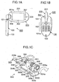
- FIGs. 1A and 1B are outline views of this embodiment in a state wherein the upper unit is so unfolded as to become perpendicular to the lower unit, and the display surface is rotated sideways toward a camera section opening portion formed in a side surface of the lower unit.
- Fig. 1C shows the structure of a portion near a biaxial hinge (movable connecting member) 300 used in this embodiment.
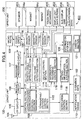
- FIG. 4 is a schematic block diagram of an electric circuit section 400 according to this embodiment.
- the cellular phone set 500 shown in Figs. 1A to 1C is mainly comprised of three sections, namely a lower unit 100 having an operating section, an upper unit 200 having a display section, and the biaxial hinge 300 serving as a movable joining member (universal hinge portion) which pivotally/rotatably couples the lower unit 100 and upper unit 200.
- the lower unit 100 and upper unit 200 have flat, elliptic shapes having predetermined thicknesses and almost the same size.
- the lower unit 100 and upper unit 200 are mechanically coupled to each other via the biaxial hinge 300.
- the upper unit 200 is designed to freely rotate/pivot about the biaxial hinge with respect to the lower unit 100.
- the lower unit 100 and upper unit 200 are electrically connected to each other by a proper connection means via the biaxial hinge.
- the respective sections enclosed with a dashed line 100A in Fig. 4 are housed or mounted in an outer case 101 of the lower unit 100.
- An operating section 102A constituted by a plurality of operation keys 102 for the use of the functions of the cellular phone set 500 is disposed on a one surface (operation surface) 101a of the lower unit 100.
- An opening portion for the microphone 103 is formed in the distal end portion of the same operation surface.
- a first pivot shaft (horizontal rotating shaft) 301 is pivotally fixed on the operation surface almost vertically at a middle position in the direction of width which is near the proximal end portion of the operation surface and spaced apart from an edge portion of the lower unit by a predetermined distance (almost 1/2 the thickness of the upper unit), with the distal end portion of the shaft protruding.
- a dashed line 200A in Fig. 4 The respective portions (to be described later) enclosed with a dashed line 200A in Fig. 4 are housed or mounted in an outer case 201 of the upper unit 200.
- a display unit 202 having an almost rectangular shape is disposed on one surface (display surface) 201a of the upper unit in portrait orientation.
- a speaker 203 is disposed on the distal end portion.
- a compact sub-display unit 206 is disposed on the surface opposite to the display surface 201a.
- a second pivot shaft (opening-closing/rotating shaft) 302 is pivotally mounted on the upper unit proximal end portion (coupling side) so as to be located at a substantially middle portion in the direction of thickness of the upper unit.
- the middle portion of the second pivot shaft 302 is pivotally coupled to the distal end portion of the first pivot shaft 301, and brackets 303 are attached to the distal end portions of the shaft portion extending to two sides.
- the brackets 303 are firmly fixed to the upper unit 200 from the inside.
- the cellular phone set 500 is mechanically designed such that the proximal end portions of the upper and lower units 200 and 100 are coupled to each other by the biaxial hinge 300 including two orthogonal pivot shafts which can pivot independently.
- This biaxial hinge 300 is comprised of the first metal pivot shaft (to be also referred to as the horizontal rotating shaft hereinafter) 301 pivotally fixed to a metal base plate 304 housed in the lower unit 100 and fixed thereto from the inside, with the distal end portion of the shaft vertically protruding from the operation surface of the lower unit, and the second metal pivot shaft (to be also referred to as the opening-closing/rotating shaft hereinafter) 302 which extends through the distal end portion of the horizontal rotating shaft 3ui at a right angle with respect to the horizontal rotating shaft 301 and pivotally' fixed thereto so as to be horizontal (parallel to the lower unit).
- the first metal pivot shaft to be also referred to as the horizontal rotating shaft hereinafter
- the second metal pivot shaft to be also referred to as the opening-closing/rotating shaft hereinafter
- Click plate biasing springs 305 in the form of coils and annular metal click plates 306 are wound, in a loosely fitted state, around the extending shaft portions of the opening-closing/rotating shaft 302 which extend to the two sides.
- Each of the L-shaped metal brackets 303 is fixed to a corresponding one of the distal end portions of the extending shaft portions at one end 303a.
- the other end 303b of the bracket 303 is formed into a mount wing portion 303c which is an L-shaped leg portion bent at a right angle and extending horizontally.
- the distal end portion of the horizontal rotating shaft 301, the opening-closing/rotating shaft 302, the brackets 303, and the like are housed in the upper, unit 200, and the brackets 303 are fixed to the upper unit 200 from the inside by using mount holes 303d formed in the mount wing portions 303c.
- the horizontal rotating shaft 301 and opening-closing/rotating shaft 302 can independently pivot within limited ranges.
- the horizontal pivot range of the horizontal rotating shaft 301 is limited to ⁇ 180° and the pivot range of the opening-closing/rotating shaft 302 is limited to 0° to 180° by providing restriction means (stoppers) for the respective rotating shaft mechanisms.
- Ventpers restriction means
- Horizontal rotation is restricted by a horizontal rotating shaft restriction means (stopper)
- opening-closing rotation is restricted by abutting the click mechanism against the outer case.
- the base plate 304 has a substantially rectangular shape.
- One long side portion 304a of the base plate 304 conforms to the curved shape of the coupling side end portion of the outer case of the lower unit.
- a long guide hole 304c having a predetermined width and predetermined length is formed in the middle portion of the long side portion at a predetermined distance from the other long side portion 304b of the base plate 304.
- a middle portion of the long side portion 304b which corresponds to the long guide hole 304c is cut away by a predetermined width. This forms a guide rod 304d having a rectangular cross-section on the long side portion 304b.
- a horizontal rotation angle restricting stopper, piece 307 is fitted on the guide rod 304d so as to be slidable by a predetermined distance.
- a lock pawl 307a protrudes from the lower middle portion of the horizontal rotation angle restricting stopper piece 307 toward the horizontal rotating shaft 301.
- a projection 301a that comes into contact with the lock pawl 307a is formed on the lower end of the horizontal rotating shaft 301 and rotates together with the horizontal rotating shaft 301.
- the horizontal pivot range (rotation angle) of the upper unit is restricted.
- the horizontal rotation angle restricting stopper piece 307 in order to restrict the rotation angle to ⁇ 180° (the -upper unit rotates through 180° clockwise and counterclockwise from the completely folded state), the horizontal rotation angle restricting stopper piece 307 is designed to slide by an amount corresponding to the width of the projection 301a of the horizontal rotating shaft stopper. This prevents the upper unit 200 from rotating beyond the folding position.
- a lock mechanism for holding a rotation angle with weak force be provided in accordance with the middle position (rotation angles of +90° and -90°) between the two positions, i.e., the normal voice communication position and the folding position.
- the click mechanism is a mechanism for generating an attracting torque for the open state and closed state (a torque that attracts the upper unit toward the opening position or closing position when it comes close to the opening position or closing position) and generating a holding torque at the position.
- the click mechanism in this embodiment is comprised of the click plates 306 having click plate projections 306a, bracket grooves 308, and the click plate biasing springs 305.
- the click plate projections 306a protruding toward the bracket side (outside) are formed on the click plates 306.
- the bracket grooves 308 are formed in the inward surfaces of the brackets 303.
- the bracket grooves 308 engage with the click plate projections 306a when the brackets 303 are at a predetermined pivot position.
- the bracket grooves 308 are located at positions (e.g., angles of 160° and 180°) where clicks are produced at the closing and opening positions.
- the click plate biasing springs 305 press the click plates 306 against the brackets 303.
- This biasing force defines a click torque.
- the illustration of the click plate biasing springs 305 is partly omitted, and hence the click plate biasing springs 305 look as if they were separated from the click plates 306. In fact, however, the biasing springs 305 are compressed and mounted between the click plates 306 and horizontal rotating shaft 301 and always bias the click plates 306 outward.
- a click is produced when the click plate projections 306a fall into the bracket grooves 308 at a predetermined opening/closing position. Note that the frictional force between the click plates 306 and the brackets 303 holds an open/closed state (unfolding angle) with weak force even at' positions other than the click producing positions.
- the upper and lower units can be electrically connected to each other by a known proper method.
- the horizontal rotating shaft and opening-closing/rotating shaft may be formed from hollow shafts, and a stranded wire is sequentially passed through the hollow portions, thereby establishing necessary electrical connection between the upper and lower units.
- film-like FPCs Flexible Print Circuits
- they are preferably wound around the respective rotating shafts by one or more turns.
- the opening-closing/rotating shaft can pivot with respect to the horizontal rotating shaft.
- an arrangement in which an opening-closing/rotating shaft and a horizontal shaft-like portion are firmly fixed and brackets are pivotally fixed to the two end portions of the horizontal shaft-like portion can be used in the same manner as the above biaxial hinge.
- This structure allows the upper and' lower units 200 and 100 to independently pivot in the horizontal direction and opening/closing direction.
- Such a biaxial hinge arrangement can be considered to make the shaft-like portion and brackets form an opening-closing/rotating shaft (second pivot shaft).
- the biaxial hinge according to the present invention therefore includes this arrangement.
- the cellular phone set includes an antenna 104, an RF circuit 105, a modem circuit 106, a baseband processing circuit 107, a codec circuit 108, the control section 109, the microphone 103, the operation keys 102, a notification means 110, and three magnetic sensors 111a, 111b, and 111c for detecting the position of the upper unit (its posture with respect to the lower unit).
- the cellular phone set according to this embodiment also includes the camera section 121 for sensing a moving image or still image, the information storage section 120 for recording received information or the information input from the camera section 121, microphone 103, and the like, and the setting information storage section 119 which stores various setting information associated with information recording and information recording cancellation depending on the relative position of the upper and lower units or the like.
- These functional sections are mounted in the lower unit 100.
- An opening portion for the camera section 121 is formed in one side surface of the lower unit 100.
- the control section 109 includes an upper unit posture detection means (rotation/open-close detecting section) of discriminating the open-close/pivot state of the upper unit, which is constituted by a rotation angle detecting section 112 for discriminating the rotation angle of the upper unit 200 on the basis of an output from each magnetic sensor 111, and an open/close detecting section 113 for discriminating an open/closed state or an upper or lower surface, and a function (communication control section 117) of discriminating a communication state.
- the control section 109 further includes a display control section 114 for controlling the orientation and the like of display contents in accordance with the display contents and outputs from the rotation angle detecting section 112 and open/close detecting section 113, a terminating/on-hook control section 115.
- the control section 109 also has a recording section control means (information recording control section 118) for managing the storage capacity and the like of the information storage section 120 described above, and a timepiece function using a timepiece control section (not shown).
- the RF circuit 105 includes a reception circuit, transmission circuit, and frequency synthesizer (none of which are shown).
- the operation keys 102 constituting the operating section include a known transmission key, alphabet/kana/kanji/numeral conversion keys, a power ON/OFF key, a crisscross key used for cursor operation, an end key, and the like.
- the cellular phone set according to this embodiment further includes the speaker 203, a magnet 204a located in correspondence with the magnetic sensors 111a and 111b, a magnet 204c located in correspondence with the magnetic sensor 111c, the display unit (liquid crystal display: LCD) 202 serving as a main screen, a touch panel mechanism 205 incorporated in the surface of the display unit 202, the sub-display unit 206, and sub-operation keys 207.
- These functional sections are mounted in the upper unit 200.
- the speaker 203 severs both as a telephone receiver and the notification means 110.
- the above respective sections constituting the electric circuit section are known, and hence a detailed description of the arrangement, function, and the like thereof will be omitted in this specification.
- the upper unit 200 can open/close (can pivot about the second pivot shaft 302) with respect to the lower unit 100 and also can pivot about the first pivot shaft 301 with respect to the lower unit 100. Therefore, pivoting of the upper unit 200 in the direction of the upper/lower surfaces is limited to a direction perpendicular to the second pivot shaft 302.
- the upper unit 200 can pivot about the first pivot shaft position and move to an arbitrary position on one surface side of the lower unit 100.
- the upper unit 200 can be turned upside down and located at the same position.
- the lower unit 100 and upper unit 200 can take various relative postures as needed, and the relative posture can be held at a predetermined lock position by the horizontal rotating shaft restriction means and click mechanism.
- the relative posture at each lock position can be detected by the upper unit posture detection means constituted by the magnetic sensors 111 described above, the magnets 204 that work in cooperation with the magnetic sensors 111, and the rotation angle detecting section 112 and open/close detecting section 113 which process outputs from the magnetic sensors 111.
- Figs. 5A and 5B are schematic views, for explaining the arrangement of the magnetic sensors and magnets in this embodiment.
- the four Hall elements (magnetic sensors) 111 are arranged in the lower unit 100 with their sensitive sides facing the operation surface.
- the two Hall elements 111a and 111b are arranged on an arc centered on the horizontal rotating shaft 301 and having a predetermined radius, a lower half arc in Fig. 5A, so as to be located on radial lines each forming an angle of 45° with the major axis of the lower unit (the center opening angle: 90°).
- the third Hall element 111d is placed at the intersection of the major axis of the lower unit and the arc centered on the horizontal rotating shaft 301 and having the.predetermined radius.
- the fourth Hall element 111c is placed on one side of the distal end portion of the lower unit. Each Hall element can also detect the direction of the magnetic field produced by a corresponding one of the magnets.
- a semi-annular magnet 204a. magnetized in the direction of thickness is mounted in.the upper unit 200 along the arc centered on the first pivot shaft 301 on the lower side in Fig. 5B.
- the magnet 204c is mounted.on the distal end portion of the upper unit in correspondence with the Hall element 111c.
- the semi-annular magnet need not always be used, and separate magnets may be arranged at positions corresponding to the Hall elements 111a and 111b, respectively.
- Figs. 6A and 6B are views for explaining the positions of the magnets corresponding to the Hall elements of the lower unit 100 at the respective main pivot positions of the upper unit with respect to the lower unit.
- Fig. 6A shows a case wherein the upper and lower units are parallel to each other.
- reference symbols Lo1 and Lo4 denote the positions of the magnets 204a and a magnet 204b when the two units are folded with the display surface facing outside.
- the current state (posture) of the upper unit can be discriminated from outputs from the rotation angle detecting section 112 and open/close detecting section 113 described above.
- Reference symbol Lo2 denotes the position of the magnet 204a when the upper unit pivots through 90° clockwise in.Fig. 6A. In this case, since an output is obtained from only the Hall element 111b, the state (posture) of the upper unit can be discriminated.
- Reference symbol Lo3 denotes the position of the magnet 204a when the upper unit further pivots through 90° clockwise (normal voice communication posture) in Fig. 5A. In this case, since no output is obtained from any Hall elements, the state (posture) of the upper unit can be discriminated.
- the magnet 204a When the two units are folded with the display surface facing inside, the magnet 204a is also located at the position Lo1 (the direction of the magnetic field is opposite to that in the case shown in Figs. 6A and 6B). In this case, however, since the magnet 204c is located at a position Lo4' and does not coincide with the Hall element 111c, the folded state of the units with the display surface facing inside can be discriminated.
- Fig. 6B shows a case wherein the upper unit is in an upright posture in which the upper unit is almost perpendicular to the lower unit, and the direction of width of the upper unit is parallel to the major axis of the lower unit.
- the display surface side of the upper unit faces the camera opening portion.
- the magnet 204a is located at a position Lo5.
- the magnet 204b (not shown) is located at the longest distance from the lower unit.
- the current state (posture) of the upper unit since an output is obtained from' only the Hall element 111d, the current state (posture) of the upper unit, including whether the display surface faces outside or inside, can be discriminated, from outputs from the rotation angle detecting section 112 and open/close detecting section 113.
- the display surface side of the upper unit faces a side opposite to the camera opening portion, the' state (posture) of the upper unit can be discriminated from the output obtained from only the Hall element 111d.
- the lower and upper units can take various relative positions (relative postures) as needed.
- the relative posture of the units can be held.
- the postures of the units can be separately detected (discriminated) by the upper unit posture detection means constituted by the magnetic sensors 111 described above, the magnets 204 that work in cooperation with the magnets, and the like.
- Fig. 7A is an outline view showing a state wherein the embodiment is folded in a direction in which the display surface of the upper unit faces the lower unit. This state is the same as the state wherein a conventional cellular phone set is folded. In this state, the overall cellular phone set is compact and easy to carry. In addition, the display surface is protected by not being exposed to the outside. Note that information in a minimum range is displayed on the sub-display unit 206.
- Fig. 7B is an outline view showing a state (normal voice communication position) wherein the upper unit 200 in the state shown in Fig. 7A is pulled upward and unfolded. In this state, the user can check displayed information, perform various operations, and make voice communication.
- Fig. 7C is an outline view showing a state wherein the upper unit 200 in, for example, the state shown in Fig. 7B is pivoted through about 90° along a plane parallel to the operation surface 101a of the lower unit 100. At this time, the display section is set in landscape orientation. Note that when the upper unit in the folded state shown in Fig: 7D is slid and pivoted counterclockwise, the cellular phone set is also set in the state shown in Fig. 7C.
- the upper unit posture detection means described above detects this positional relationship, and'the display control section 114 converts the display contents to be displayed on the display unit 202 in accordance with the upward/downward direction of the operation surface 101a and displays the contents in landscape orientation (with the left and right sides of the display contents coinciding with the long side direction of the display unit).
- the corresponding processing contents are matched with the display direction.
- the display surface in landscape orientation allows the user to easily check a large volume of character information and makes a landscape image more eye friendly.
- the cellular phone set according to this embodiment allows the user to perform proper operation as needed, e.g., seeing information upon setting the display section in landscape orientation in an open state.
- the upper unit 200 in the normal voice communication position (standard unfolded state) shown in Fig. 7B can be pivoted through about 90° counterclockwise in the direction of the display surface.
- the upper unit 200 and lower unit 100 become almost perpendicular to each other in substantially the same plane, and the display unit is set in landscape orientation with respect to the upward/downward direction of the operation surface.
- the upper unit posture detection means detects that the upper and lower units are in such a positional relationship.
- the display control section 114 converts the display contents to be displayed on the display unit 202 in accordance with the upward/downward direction of the operation surface (making the left and right sides of the display contents coincide with the long side direction of the display unit; the direction of the display contents becomes relatively opposite to that.in the state shown in Fig. 7C) and displays the contents in landscape orientation.
- the units can be closed in a state opposite to the standard state, i.e., can be closed while the display section that normally faces inside is made to face outside.
- Fig. 7D is an outline view showing a state wherein the upper unit 200 is folded with respect to the lower unit 100 with the display surface of the upper unit facing outside.
- the upper unit 200 is rotated a half turn from the state wherein the cellular phone set is open (Fig. 7B)
- the upper unit can be closed in the opposite direction with its display surface facing outside, as shown in Fig. 7D.
- the cellular phone set becomes compact and easy to carry, and the user can check display contents while the cellular phone set is folded.
- the second operating section 207 since the second operating section 207 is exposed to the outside, the user can perform predetermined operation in accordance with the display contents by using' the second operating section 207.
- the upper unit posture detection means may detect the folded state shown in Fig. 7D, and the display contents may be displayed upside down on the display unit.
- the corresponding processing contents are matched with the display direction.
- the user can read displayed information and perform necessary operation while holding the cellular phone set in his/her hand in the same manner as in the standard folded state without changing the orientation of the cellular phone set from the normal orientation.
- the embodiment is in the state (upright posture) shown in Figs. 1A and 1B.
- the opening portion for the camera section 121 also faces the user.
- the user can check his/her face sensed by the camera section 121 on the display unit 202. This allows the user to use the cellular phone set as a videophone set while transmitting an image of the user himself/herself.
- This state is also suitable when the user records his/her image.
- the embodiment is in the state (upright posture) shown in Figs. 3A and 3C.
- the opening portion for the camera section 121 is located on the side opposite to the display unit 202.
- This state is therefore suitable when the user uses the camera section 121 to sense and record outer scenery, others, and the like while checking them on the display unit 202. Note that recording of an image and the like can be controlled in association with upright posture detecting operation, as will be described later.
- the recording section is set in the information recording mode when a predetermined relative posture, of the relative postures (relative positions) of the lower and upper units, is detected by the sensors 111 and the magnets 204 which work in cooperation therewith during voice communication or a standby period.
- the user can therefore make a setting in advance to enable the information recording mode when the relative position (relative posture) of the lower and upper units shifts to a predetermined posture during voice communication or a standby period.
- the user performs setting operation for input setting to enable the voice information recording mode when, for example, the relative position of the lower and upper units changes in such a manner that the upper unit in the position (posture) shown in Fig. 7B is slightly pivoted about the second pivot shaft 302 (opening/closing operation) so as to shift the current mode to the information recording mode.
- the corresponding information is then stored in the setting information storage section 119.
- a click mechanism is also provided at a pivot position where the information recording mode is started.
- the current mode shifts to the information recording mode to store the voice information input from the microphone 103 in the information storage section 120 for a predetermined period of time or store information corresponding to a predetermined storage capacity therein, if the cellular phone set is in a standby period.
- recording of received information is started in response to the same operation (relative position shift), and information is recorded on the information storage section 120 for a predetermined period of time or information corresponding to a predetermined storage capacity is recorded thereon.
- a control procedure, for enabling the information recording mode when the relative position of the lower and upper units shifts to the above position is set and stored in the setting information storage section 119 in advance.
- a control procedure for canceling the information recording mode when the upper unit of the cellular phone set at a position at which the information recording mode is enabled is pivoted to be shifted again to the position shown in Fig. 7B can be set.
- the following setting can be selectively made.
- the user can make input setting to enable the voice information recording mode when the relative position of the lower and upper, units changes such that the upper unit at the position (posture) shown in Fig. 7B is pivoted to the position (posture) shown in Fig. 7C or the like.
- the corresponding information is then stored in the setting information storage section 119.
- the user can make input setting for a control procedure for canceling the information recording mode when the upper unit at the position shown in Fig. 7C is further pivoted to the position shown in Fig. 7B, and stores the setting in the setting information storage section 119, and can also set a control procedure for canceling the information recording mode when the upper unit of the cellular phone set at the position shown in Fig. 7C at which the information recording mode is enabled is pivoted to be shifted to the position shown in Fig. 7B.
- the current mode shifts to the information recording mode.
- the cellular phone set is in a standby state, the voice information input from the microphone 103 is recorded on the information storage section 120.
- recording of received information is started in response to the same operation (relative position shift) to record information on the information storage section 120 for a predetermined period of time or record information corresponding to a predetermined storage capacity thereon.
- the recording operation is immediately stopped.
- the cellular phone set may be designed such that when the user slightly pivots the upper unit of the cellular phone set in the state shown in Fig. 7B about the first pivot shaft 301 (horizontal pivoting), the current mode shifts to the voice information recording mode during a standby period or voice communication.
- the cellular phone set is controlled in accordance with the same operation as described above to record the received image information on the information storage section 120.
- the embodiment of the present invention has the camera section 121.
- the operation state of the camera section 121 and recording of image output (output information) therefrom can also be controlled on the basis of the relative position of the lower and upper units or its change.
- FIG. 1A and 1B and Figs. 3A to 3C show examples of the relative position of the lower and upper units at which the camera section 121 which senses a moving image or still image is activated.
- the display unit 202 on the display surface 201a of the upper unit is located at a position to face the operator, and the camera section 121 (opening portion) on one side surface of the lower unit is located at a position to face an object to be sensed.
- the display unit 202 on the display surface 201a of the upper unit is located at a position to face the operator, and the camera section 121 on one side surface of the lower unit is located at a position to face the object.
- This embodiment is configured such that when the relative position (relative posture) of the lower and upper units of the cellular phone set in a standby state is changed (operated) to the state shown in Figs. 1A and 1B, the mode of recording information from the camera section 121 and microphone 103 is enabled. If predetermined setting operation is done in advance, therefore, when the user moves the upper unit to change the positional relationship between the two units to the state shown in Figs. 1A and 1B during a standby period, the current mode shifts to the information recording mode. As a consequence, image information (user's portrait in the normal use state) is recorded on the information storage section 120 for a predetermined period of time or information corresponding to a predetermined storage capacity is recorded thereon.
- This embodiment is also configured to allow the following setting.
- the user slightly changes the posture of the upper unit from the posture shown in Figs. 1A and 1B during voice communication using the cellular phone set as a videophone set, recording of received information (image information and/or voice information) is started, and information is recorded on the information storage section 120 for a predetermined period of time or information corresponding to a predetermined storage capacity is recorded thereon.
- this embodiment is configured to enable the mode of recording information from the camera section 121 and microphone 103 when the user changes (operates) the relative position (relative posture) of the lower and upper units of the cellular phone set in a standby state to the state shown in Figs. 3A to 3C. If, therefore, predetermined setting operation is done in advance and the corresponding information is stored in the setting information storage section 119, when the user moves the upper unit to change the positional relationship between the two units to the state shown in Figs.
- the current mode shifts to the information recording mode to store image information (outer scenery or the like in the normal use state) from the camera section 121 in the information storage section 120 for a predetermined period of time or store information corresponding to a predetermined storage capacity therein.
- the user makes desired settings concerning information recording during a standby period.
- the setting contents are stored in the setting information storage section 119.
- the user selects the type of information which he/she wants to store as a setting item.
- voice information from the microphone and image information from the camera section can be separately or simultaneously selected.
- a proper upper unit posture (position) is associated as an initial setting with the selected information.
- a recording start posture can be input/designated and associated with each information, as needed.
- a proper recording time (recording capacity) is associated as an initial setting with the selected information.
- a recording time can be input/designated and associated with each information, as needed.
- Manual operation corresponding to a change in unit position for the cancellation of the recording mode can be arbitrarily and additionally set.
- the user can separately or simultaneously select reception contents (voice information and image information) in a voice communication mode.
- a proper upper unit posture position
- a recording start posture can be input/designated and associated with each information, as needed.
- a proper recording time (recording capacity) is associated as an initial setting with the selected information.
- a recording time can be input/designated and associated with each information, as needed.
- Manual operation corresponding to a change in unit position for the cancellation of the recording mode can be arbitrarily and additionally set.
- the unit posture detection means detects this, and the information recording control section 118 operates.
- the image information sensed by the camera section 121 (input voice from the microphone 103 as well depending on the settings) is recorded on the information storage section 120 for a predetermined period of time.
- the recording mode is canceled (recording is stopped) even in the process of recording when the user moves the upper unit from the unit posture shown in Figs. 3A to 3C.
- the unit posture detection means detects this, and the information recording control section 118. operates to record input voice from the microphone 103 as a memo on the information storage section 120 for a predetermined period of time.
- the unit posture detection means detects this, and the information recording control section 118 operates to record voice information on the information storage section 120 for a predetermined period of time during voice communication.
- the recording mode is canceled (recording is stopped) even in the process of recording when the user returns the upper unit to the unit posture shown in Fig. 7B.
- opening-closing/pivoting operation of the upper and lower units which are openably and pivotally coupled to each other is detected during voice communication or a standby period, and information such as voice information and image information is recorded. Therefore, information such as received information, image information from the camera section, and voice information can be easily and simply recorded, thus greatly improving the operability.
- the cellular phone set according to this embodiment can be folded with the display section facing outside, and hence the user can read mail, see a map or other images, and check a communicating partner upon call termination on the display while the cellular phone set is closed.
- This allows the user to perform operation, e.g., receiving a telephone call upon determining display contents, while the cellular phone set is closed.
- the cellular phone set is folded with the display section facing outside, the user can carry it compactly while seeing the display screen on which a map or the like is displayed.
- the user can also carry the cellular phone set while the cellular phone set is folded with the display section facing inside to protect it as in the conventional manner.
- one cellular phone set having the same size as that of the conventional cellular phone set can cope with contents display in both portrait orientation and landscape orientation.
- Movement from a specific position, movement from a specific position for a predetermined short period of time, a return to the specific position, a shift from a specific position to another specific position, and the like are associated with information recording control or other function control operations.
- control operations can be conceived as follows. For example, when the user moves the cellular phone set during a standby period which is set in the state shown in Figs. 3A to 3C and returns it to the state shown in Fig. 3A to 3C within a predetermined short period of time, the outer scenery (image information) monitored by the display unit is recorded for a predetermined period of time.
- movement of the cellular phone set in the standby state shown in Figs. 3A to 3C to a lock position which slightly differs from the position in Figs. 3A to 3C is associated with the start of recording of image information, and a return to the state shown in Figs. 3A to 3C in the recording mode is associated with the interruption of recording.
- the cellular phone set may be designed to allow the user to make settings to arbitrarily select and record voice information, moving image information, still image information, and the like.
- the recordable capacity of the information storage section may be monitored, and for example, moving image information and voice information, still image information and voice information, only voice information, or only still image information may be selected to be recorded for a predetermined period of time in accordance with the recordable capacity.
- the present invention can be configured to record only necessary type of information.
- the present invention can be applied to recording of voice information in a folding cellular phone set having no camera section.
- Other portions and association of the positions of the two units with information recording control operations can be variously modified within the technical range of the present invention.
- the structure according to this embodiment uses the hinge portion (movable joining member).
- the present invention can be applied to for example, a folding cellular phone set using one rotating shaft in which voice is handled as information to be stored.
- the present invention can be applied to any cellular phone set which has upper and lower units coupled to be relatively movable and allows the detection of the relative posture of the units.
- the cellular phone set has been exemplified as an embodiment of the present invention.
- the present invention is not limited to this and can be applied to a portable information terminal apparatus such as a PDA. In this case' as well, the same effects as those described in the embodiment can be obtained.
Description
- The present invention relates to a portable information terminal, such as a cellular phone set which has a folding type structure and information recording function and, more particularly, to an improvement in information recording control.
- Conventionally, as the structures of portable information terminals, especially cellular phone sets of straight type structures, folding type structures, and the like have been used. Among these cellular phone sets, folding structure type cellular phone sets have been popularized and risen in demand because they can be folded compact. In addition, recently, new folding portable information terminals each having two units such as upper and lower units openably and pivotally coupled to each other have been proposed as in
Japanese Unexamined Patent Publication No. 11-30226 Japanese Unexamined Patent Publication No. 11-215218 Japanese Patent Application No. 2001-303959 - Some portable information terminals have a function of recording information such as voice information and image information. For example, there have proposed many portable information terminals designed to improve convenience by recording received information during voice communication and recording information as a memo during a standby period.
- In addition, a portable information terminal which has a camera section to record sensed image information or moving image information and transmit it has been widely known. Apparatuses of this type are disclosed in, for example,
Japanese. Unexamined Patent Publication No. 10-257460 Japanese Unexamined Patent Publication No. 2001-275094 Japanese Unexamined Patent Publication No. 2001-320463 - In order to use' a portable information terminal having a camera section as a videophone which senses a user himself/herself, a camera opening portion is located on a surface in the same direction as that of the surface on which an image monitoring display unit is disposed. In order to use this terminal to take a picture of the surroundings of the user, a camera opening portion is located on a surface opposite to the surface on which the image monitoring display unit is disposed. For this purpose, each of the portable information terminals described above is designed to change the relative posture of the camera opening portion and monitoring display unit so as to allow the use of the terminal as a videophone or to take a picture of the surroundings of the user. The apparatus disclosed in
Japanese Unexamined Patent Publication. No. 10-2574,60 Japanese Unexamined Patent Publication No. 2001-275094 Japanese Unexamined Patent Publication No. 2001-320463 - In order to use the information recording function of a conventional portable information terminal, however, the user must perform a series of operations by using a predetermined operating section. This applies to the above new folding portable information terminal having the upper and lower units openably and pivotally coupled to each other. The operation in this case is cumbersome for the user. In addition, it is difficult to perform this operation during voice communication. Demand has therefore arisen for an improvement in the usability of the information recording function.
- A folding portable information terminal according to the preamble part of
claim 1 is known fromUS 2001/004269 A1 . -
US 5297146 A1 discloses a communication terminal and its control method which allow the realization of parallel operation of a plurality of communications with use of a plurality of date channels allocated to each line of an ISDN-Network. - It is an object of the present invention to provide a highly operable folding portable information terminal having the above-described upper and lower units openably or openably and pivotally coupled to each other, in which an information recording mode for voice information, image information, and the like is set upon detection of the opening-closing/pivoting operation of the unit during voice communication or a standby period, so that an information recording function of recording received information during voice communication and recording information as a memo during a standby period can be easily and simply used.
- This object is solved by the features of
claim 1. - Advantageous embodiments are mentioned in the subclaims.
- The above and many other objects, features and advantages of the present invention will become manifest to those skilled in the art upon making reference to the following detailed description and accompanying drawings in which a preferred embodiment incorporating the principle of the present invention are shown by way of illustrative examples.
-
- Figs. 1A and 1B are outline views showing an embodiment of a cellular phone set according to the present invention, and Fig. 1C is a perspective view showing a main part to explain the structure of a biaxial hinge used in the embodiment;
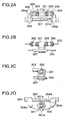
- Figs. 2A to 2D show the structure of the biaxial hinge used in the embodiment of the present invention, in which Fig. 2A is a plan view, Fig. 2B is a front view, Fig. 2C is a side view, and Fig. 2D is a bottom view;
- Figs. 3A to 3C are outline views showing the cellular phone set according to the same embodiment in different postures;
- Fig. 4 is a schematic block diagram of an electric circuit section in the embodiment of the present invention;
- Figs. 5A and 5B are schematic views for explaining the arrangement of magnetic sensors and magnets according to the embodiment of the present invention;
- Figs 6A and 6B are views showing the positions of the magnets with respect to the Hall elements in the lower unit in correspondence with the main pivot positions of the upper unit with respect to the lower unit in the embodiment of the present invention; and
- Figs. 7A to 7D are outline views for explaining the main lock positions (relative postures) of the lower and upper units in the embodiment of the present invention.
- A preferred embodiment of the present invention will be described below with reference to the accompanying drawings.
- A folding portable information terminal according to the present invention is set in an information recording mode during voice communication or a standby period upon detection of opening-closing/pivoting operation of upper and lower units which are openably or pivotally coupled to each other. This makes it possible to easily and simply record received information such as voice information during voice communication or information as a memo such as voice information or image information during a standby period.
- The accompanying drawings show an embodiment of a folding cellular phone set as a portable information terminal according to the present invention. Many components of the arrangement of a cellular phone set 500 according to this embodiment which will be described below are common to the folding cellular phone set disclosed in
Japanese Patent Application No. 2001-303959 - In addition to the arrangement disclosed in
Japanese Patent Application No. 2001-303959 camera section 121 for sensing a moving image or still image, aninformation storage section 120 for recording received information or the information input from thecamera section 121, amicrophone 103, or the like, and a settinginformation storage section 119 which stores various setting information associated with information recording and information recording cancellation depending on the relative position of the upper and lower units and the like. - As compared with the control section in
Japanese Patent Application No. 2001-303959 control section 109 in this embodiment further includes a function (rotation/open-close detecting section) of discriminating the open-close/pivot state of the units, a timepiece function (timepiece control section), a function (communication control section 117) of discriminating a communication state, and a function (information recording control section 118) of managing the storage capacity and the like of the information' storage section. - The respective portions of the embodiment of the present invention will be sequentially described below. Figs. 1A and 1B are outline views of this embodiment in a state wherein the upper unit is so unfolded as to become perpendicular to the lower unit, and the display surface is rotated sideways toward a camera section opening portion formed in a side surface of the lower unit. Fig. 1C shows the structure of a portion near a biaxial hinge (movable connecting member) 300 used in this embodiment.
- The outline views of Figs. 3A to 3C shows the state of the same embodiment in which the upper unit is so unfolded as to become perpendicular to the lower unit, and the display surface is rotated sideways toward the side opposite to the camera section opening portion, thereby taking a different posture. Fig. 4 is a schematic block diagram of an
electric circuit section 400 according to this embodiment. - The cellular phone set 500 shown in Figs. 1A to 1C is mainly comprised of three sections, namely a
lower unit 100 having an operating section, anupper unit 200 having a display section, and thebiaxial hinge 300 serving as a movable joining member (universal hinge portion) which pivotally/rotatably couples thelower unit 100 andupper unit 200. - The
lower unit 100 andupper unit 200 have flat, elliptic shapes having predetermined thicknesses and almost the same size. Thelower unit 100 andupper unit 200 are mechanically coupled to each other via thebiaxial hinge 300. Theupper unit 200 is designed to freely rotate/pivot about the biaxial hinge with respect to thelower unit 100. In addition, thelower unit 100 andupper unit 200 are electrically connected to each other by a proper connection means via the biaxial hinge. - The respective sections enclosed with a dashed line 100A in Fig. 4 are housed or mounted in an
outer case 101 of thelower unit 100. An operating section 102A constituted by a plurality ofoperation keys 102 for the use of the functions of the cellular phone set 500 is disposed on a one surface (operation surface) 101a of thelower unit 100. An opening portion for themicrophone 103 is formed in the distal end portion of the same operation surface. A first pivot shaft (horizontal rotating shaft) 301 is pivotally fixed on the operation surface almost vertically at a middle position in the direction of width which is near the proximal end portion of the operation surface and spaced apart from an edge portion of the lower unit by a predetermined distance (almost 1/2 the thickness of the upper unit), with the distal end portion of the shaft protruding. - The respective portions (to be described later) enclosed with a dashed line 200A in Fig. 4 are housed or mounted in an
outer case 201 of theupper unit 200. Adisplay unit 202 having an almost rectangular shape is disposed on one surface (display surface) 201a of the upper unit in portrait orientation. Aspeaker 203 is disposed on the distal end portion. Note that acompact sub-display unit 206 is disposed on the surface opposite to thedisplay surface 201a. - A second pivot shaft (opening-closing/rotating shaft) 302 is pivotally mounted on the upper unit proximal end portion (coupling side) so as to be located at a substantially middle portion in the direction of thickness of the upper unit. The middle portion of the
second pivot shaft 302 is pivotally coupled to the distal end portion of thefirst pivot shaft 301, andbrackets 303 are attached to the distal end portions of the shaft portion extending to two sides. Thebrackets 303 are firmly fixed to theupper unit 200 from the inside. - As described above, the cellular phone set 500 according to this embodiment is mechanically designed such that the proximal end portions of the upper and
lower units biaxial hinge 300 including two orthogonal pivot shafts which can pivot independently. - The detailed structure of the pivot mechanism formed from the
biaxial hinge 300, which is used in this embodiment and a characteristic feature of the present invention, will be further described with reference to Fig. 1C and Figs. 2A to 2D. Thisbiaxial hinge 300 is comprised of the first metal pivot shaft (to be also referred to as the horizontal rotating shaft hereinafter) 301 pivotally fixed to ametal base plate 304 housed in thelower unit 100 and fixed thereto from the inside, with the distal end portion of the shaft vertically protruding from the operation surface of the lower unit, and the second metal pivot shaft (to be also referred to as the opening-closing/rotating shaft hereinafter) 302 which extends through the distal end portion of the horizontal rotating shaft 3ui at a right angle with respect to the horizontalrotating shaft 301 and pivotally' fixed thereto so as to be horizontal (parallel to the lower unit). - Click plate biasing springs 305 in the form of coils and annular
metal click plates 306 are wound, in a loosely fitted state, around the extending shaft portions of the opening-closing/rotatingshaft 302 which extend to the two sides. Each of the L-shapedmetal brackets 303 is fixed to a corresponding one of the distal end portions of the extending shaft portions at oneend 303a. Theother end 303b of thebracket 303 is formed into amount wing portion 303c which is an L-shaped leg portion bent at a right angle and extending horizontally. The distal end portion of the horizontalrotating shaft 301, the opening-closing/rotatingshaft 302, thebrackets 303, and the like are housed in the upper,unit 200, and thebrackets 303 are fixed to theupper unit 200 from the inside by using mount holes 303d formed in themount wing portions 303c. - The horizontal
rotating shaft 301 and opening-closing/rotatingshaft 302 can independently pivot within limited ranges. In this embodiment, the horizontal pivot range of the horizontalrotating shaft 301 is limited to ± 180° and the pivot range of the opening-closing/rotatingshaft 302 is limited to 0° to 180° by providing restriction means (stoppers) for the respective rotating shaft mechanisms. Horizontal rotation is restricted by a horizontal rotating shaft restriction means (stopper), whereas opening-closing rotation is restricted by abutting the click mechanism against the outer case. - The horizontal rotating shaft restriction means will be described. The
base plate 304 has a substantially rectangular shape. Onelong side portion 304a of thebase plate 304 conforms to the curved shape of the coupling side end portion of the outer case of the lower unit. Along guide hole 304c having a predetermined width and predetermined length is formed in the middle portion of the long side portion at a predetermined distance from the otherlong side portion 304b of thebase plate 304. A middle portion of thelong side portion 304b which corresponds to thelong guide hole 304c is cut away by a predetermined width. This forms aguide rod 304d having a rectangular cross-section on thelong side portion 304b. A horizontal rotation angle restricting stopper,piece 307 is fitted on theguide rod 304d so as to be slidable by a predetermined distance. Alock pawl 307a (Fig. 2D) protrudes from the lower middle portion of the horizontal rotation angle restrictingstopper piece 307 toward the horizontalrotating shaft 301. - A
projection 301a that comes into contact with thelock pawl 307a is formed on the lower end of the horizontalrotating shaft 301 and rotates together with the horizontalrotating shaft 301. When thisprojection 301a comes into contact with thelock pawl 307a of the horizontal rotation angle restrictingstopper piece 307 as the rotating shaft pivots, the horizontal pivot range (rotation angle) of the upper unit is restricted. In this embodiment, in order to restrict the rotation angle to ± 180° (the -upper unit rotates through 180° clockwise and counterclockwise from the completely folded state), the horizontal rotation angle restrictingstopper piece 307 is designed to slide by an amount corresponding to the width of theprojection 301a of the horizontal rotating shaft stopper. This prevents theupper unit 200 from rotating beyond the folding position. It is more preferable that a lock mechanism for holding a rotation angle with weak force be provided in accordance with the middle position (rotation angles of +90° and -90°) between the two positions, i.e., the normal voice communication position and the folding position. - The click mechanism will be described next. The click mechanism is a mechanism for generating an attracting torque for the open state and closed state (a torque that attracts the upper unit toward the opening position or closing position when it comes close to the opening position or closing position) and generating a holding torque at the position. The click mechanism in this embodiment is comprised of the
click plates 306 havingclick plate projections 306a,bracket grooves 308, and the click plate biasing springs 305. - The
click plate projections 306a protruding toward the bracket side (outside) are formed on theclick plates 306. Thebracket grooves 308 are formed in the inward surfaces of thebrackets 303. Thebracket grooves 308 engage with theclick plate projections 306a when thebrackets 303 are at a predetermined pivot position. Thebracket grooves 308 are located at positions (e.g., angles of 160° and 180°) where clicks are produced at the closing and opening positions. - The click plate biasing springs 305 press the
click plates 306 against thebrackets 303. This biasing force defines a click torque. Referring to Figs. 2A and 2B, the illustration of the click plate biasing springs 305 is partly omitted, and hence the click plate biasing springs 305 look as if they were separated from theclick plates 306. In fact, however, the biasing springs 305 are compressed and mounted between theclick plates 306 and horizontalrotating shaft 301 and always bias theclick plates 306 outward. A click is produced when theclick plate projections 306a fall into thebracket grooves 308 at a predetermined opening/closing position. Note that the frictional force between theclick plates 306 and thebrackets 303 holds an open/closed state (unfolding angle) with weak force even at' positions other than the click producing positions. - The upper and lower units can be electrically connected to each other by a known proper method. For example, the horizontal rotating shaft and opening-closing/rotating shaft may be formed from hollow shafts, and a stranded wire is sequentially passed through the hollow portions, thereby establishing necessary electrical connection between the upper and lower units. Alternatively, film-like FPCs (Flexible Print Circuits) may be wound around the two rotating shafts, and the two end portions of each FPC may be connected to the upper and lower units. In this case, in order to increase the durability of the FPCs, they are preferably wound around the respective rotating shafts by one or more turns.
- With the above biaxial hinge, the opening-closing/rotating shaft can pivot with respect to the horizontal rotating shaft. However, an arrangement in which an opening-closing/rotating shaft and a horizontal shaft-like portion are firmly fixed and brackets are pivotally fixed to the two end portions of the horizontal shaft-like portion can be used in the same manner as the above biaxial hinge. This structure allows the upper and'
lower units - The electric circuit and the like in this embodiment will be described next.. As shown in the block diagram of Fig. 4, the cellular phone set according to this embodiment includes an
antenna 104, anRF circuit 105, amodem circuit 106, abaseband processing circuit 107, acodec circuit 108, thecontrol section 109, themicrophone 103, theoperation keys 102, a notification means 110, and threemagnetic sensors camera section 121 for sensing a moving image or still image, theinformation storage section 120 for recording received information or the information input from thecamera section 121,microphone 103, and the like, and the settinginformation storage section 119 which stores various setting information associated with information recording and information recording cancellation depending on the relative position of the upper and lower units or the like. These functional sections are mounted in thelower unit 100. An opening portion for thecamera section 121 is formed in one side surface of thelower unit 100. - The
control section 109 includes an upper unit posture detection means (rotation/open-close detecting section) of discriminating the open-close/pivot state of the upper unit, which is constituted by a rotationangle detecting section 112 for discriminating the rotation angle of theupper unit 200 on the basis of an output from each magnetic sensor 111, and an open/close detectingsection 113 for discriminating an open/closed state or an upper or lower surface, and a function (communication control section 117) of discriminating a communication state. Thecontrol section 109 further includes adisplay control section 114 for controlling the orientation and the like of display contents in accordance with the display contents and outputs from the rotationangle detecting section 112 and open/close detectingsection 113, a terminating/on-hook control section 115. which can perform terminating control operation corresponding to the opening/closing operation and moving operation of the upper unit, and anotification control section 116 which can control incoming call notifying operation corresponding to the opening/closing operation and moving operation of the upper unit. Thecontrol section 109 also has a recording section control means (information recording control section 118) for managing the storage capacity and the like of theinformation storage section 120 described above, and a timepiece function using a timepiece control section (not shown). - The
RF circuit 105 includes a reception circuit, transmission circuit, and frequency synthesizer (none of which are shown). Theoperation keys 102 constituting the operating section include a known transmission key, alphabet/kana/kanji/numeral conversion keys, a power ON/OFF key, a crisscross key used for cursor operation, an end key, and the like. - The cellular phone set according to this embodiment further includes the
speaker 203, amagnet 204a located in correspondence with themagnetic sensors magnet 204c located in correspondence with themagnetic sensor 111c, the display unit (liquid crystal display: LCD) 202 serving as a main screen, atouch panel mechanism 205 incorporated in the surface of thedisplay unit 202, thesub-display unit 206, andsub-operation keys 207. These functional sections are mounted in theupper unit 200. Note that thespeaker 203 severs both as a telephone receiver and the notification means 110. The above respective sections constituting the electric circuit section are known, and hence a detailed description of the arrangement, function, and the like thereof will be omitted in this specification. - Characteristic operation of this embodiment will be described next with reference to the accompanying drawings. In the cellular phone set 500 according to this embodiment having the two units coupled to each other via the
biaxial hinge 300 described above, theupper unit 200 can open/close (can pivot about the second pivot shaft 302) with respect to thelower unit 100 and also can pivot about thefirst pivot shaft 301 with respect to thelower unit 100. Therefore, pivoting of theupper unit 200 in the direction of the upper/lower surfaces is limited to a direction perpendicular to thesecond pivot shaft 302. However, theupper unit 200 can pivot about the first pivot shaft position and move to an arbitrary position on one surface side of thelower unit 100. In addition, theupper unit 200 can be turned upside down and located at the same position. That is, thelower unit 100 andupper unit 200 can take various relative postures as needed, and the relative posture can be held at a predetermined lock position by the horizontal rotating shaft restriction means and click mechanism. The relative posture at each lock position can be detected by the upper unit posture detection means constituted by the magnetic sensors 111 described above, the magnets 204 that work in cooperation with the magnetic sensors 111, and the rotationangle detecting section 112 and open/close detectingsection 113 which process outputs from the magnetic sensors 111. - The mount positions of the magnetic sensors 111 and magnets 204 for detecting the relative posture of the
lower unit 100 andupper unit 200 in this embodiment will be described in detail below. Figs. 5A and 5B are schematic views, for explaining the arrangement of the magnetic sensors and magnets in this embodiment. As shown in Fig. 5A, the four Hall elements (magnetic sensors) 111 are arranged in thelower unit 100 with their sensitive sides facing the operation surface. The twoHall elements rotating shaft 301 and having a predetermined radius, a lower half arc in Fig. 5A, so as to be located on radial lines each forming an angle of 45° with the major axis of the lower unit (the center opening angle: 90°). Thethird Hall element 111d is placed at the intersection of the major axis of the lower unit and the arc centered on the horizontalrotating shaft 301 and having the.predetermined radius. Thefourth Hall element 111c is placed on one side of the distal end portion of the lower unit. Each Hall element can also detect the direction of the magnetic field produced by a corresponding one of the magnets. - As shown in Fig. 5B, a
semi-annular magnet 204a. magnetized in the direction of thickness is mounted in.theupper unit 200 along the arc centered on thefirst pivot shaft 301 on the lower side in Fig. 5B. Themagnet 204c is mounted.on the distal end portion of the upper unit in correspondence with theHall element 111c. Note that the semi-annular magnet need not always be used, and separate magnets may be arranged at positions corresponding to theHall elements - Figs. 6A and 6B are views for explaining the positions of the magnets corresponding to the Hall elements of the
lower unit 100 at the respective main pivot positions of the upper unit with respect to the lower unit. Fig. 6A shows a case wherein the upper and lower units are parallel to each other. Referring to Fig. 6A, reference symbols Lo1 and Lo4 denote the positions of themagnets 204a and amagnet 204b when the two units are folded with the display surface facing outside. At this time, since outputs can be obtained from all theHall elements angle detecting section 112 and open/close detectingsection 113 described above. - Reference symbol Lo2 denotes the position of the
magnet 204a when the upper unit pivots through 90° clockwise in.Fig. 6A. In this case, since an output is obtained from only theHall element 111b, the state (posture) of the upper unit can be discriminated. Reference symbol Lo3 denotes the position of themagnet 204a when the upper unit further pivots through 90° clockwise (normal voice communication posture) in Fig. 5A. In this case, since no output is obtained from any Hall elements, the state (posture) of the upper unit can be discriminated. - When the two units are folded with the display surface facing inside, the
magnet 204a is also located at the position Lo1 (the direction of the magnetic field is opposite to that in the case shown in Figs. 6A and 6B). In this case, however, since themagnet 204c is located at a position Lo4' and does not coincide with theHall element 111c, the folded state of the units with the display surface facing inside can be discriminated. - Fig. 6B shows a case wherein the upper unit is in an upright posture in which the upper unit is almost perpendicular to the lower unit, and the direction of width of the upper unit is parallel to the major axis of the lower unit. Assume that the display surface side of the upper unit faces the camera opening portion. In this case, when the two units are folded with the display surface facing outside, the
magnet 204a is located at a position Lo5. Note that themagnet 204b (not shown) is located at the longest distance from the lower unit. In the state shown in Fig. 6B, since an output is obtained from' only theHall element 111d, the current state (posture) of the upper unit, including whether the display surface faces outside or inside, can be discriminated, from outputs from the rotationangle detecting section 112 and open/close detectingsection 113. In addition, when the display surface side of the upper unit faces a side opposite to the camera opening portion, the' state (posture) of the upper unit can be discriminated from the output obtained from only theHall element 111d. - As described above, in this embodiment, the lower and upper units can take various relative positions (relative postures) as needed. At each of the lock positions in the horizontal pivot direction indicated by the outline views of Figs. 1A and 1B, Figs. 3A to 3C, and Figs. 7A to 7D, in particular, in a posture in which the upper unit is unfolded perpendicularly with respect to the lower unit (this posture will be referred to as an upright posture hereinafter), the relative posture of the units can be held. The postures of the units can be separately detected (discriminated) by the upper unit posture detection means constituted by the magnetic sensors 111 described above, the magnets 204 that work in cooperation with the magnets, and the like.
- Fig. 7A is an outline view showing a state wherein the embodiment is folded in a direction in which the display surface of the upper unit faces the lower unit. This state is the same as the state wherein a conventional cellular phone set is folded. In this state, the overall cellular phone set is compact and easy to carry. In addition, the display surface is protected by not being exposed to the outside. Note that information in a minimum range is displayed on the
sub-display unit 206. - Fig. 7B is an outline view showing a state (normal voice communication position) wherein the
upper unit 200 in the state shown in Fig. 7A is pulled upward and unfolded. In this state, the user can check displayed information, perform various operations, and make voice communication. - Fig. 7C is an outline view showing a state wherein the
upper unit 200 in, for example, the state shown in Fig. 7B is pivoted through about 90° along a plane parallel to theoperation surface 101a of thelower unit 100. At this time, the display section is set in landscape orientation. Note that when the upper unit in the folded state shown in Fig: 7D is slid and pivoted counterclockwise, the cellular phone set is also set in the state shown in Fig. 7C. - When the upper and lower units are in the positional relationship shown in Fig. 7C, the upper unit posture detection means described above detects this positional relationship, and'the
display control section 114 converts the display contents to be displayed on thedisplay unit 202 in accordance with the upward/downward direction of theoperation surface 101a and displays the contents in landscape orientation (with the left and right sides of the display contents coinciding with the long side direction of the display unit). At this time, with regard to information with directivity in terms of processing corresponding to operation, e.g., a direction key (cursor key), of information associated with the operating section or second operating section, the corresponding processing contents are matched with the display direction. - In the state shown in Fig.7C, the display surface in landscape orientation allows the user to easily check a large volume of character information and makes a landscape image more eye friendly. In this manner, the cellular phone set according to this embodiment allows the user to perform proper operation as needed, e.g., seeing information upon setting the display section in landscape orientation in an open state.
- Although not shown, in contrast to the above description, the
upper unit 200 in the normal voice communication position (standard unfolded state) shown in Fig. 7B can be pivoted through about 90° counterclockwise in the direction of the display surface. In this case as well, theupper unit 200 andlower unit 100 become almost perpendicular to each other in substantially the same plane, and the display unit is set in landscape orientation with respect to the upward/downward direction of the operation surface. - In this case as well, the upper unit posture detection means detects that the upper and lower units are in such a positional relationship. In accordance with this detection, the
display control section 114 converts the display contents to be displayed on thedisplay unit 202 in accordance with the upward/downward direction of the operation surface (making the left and right sides of the display contents coincide with the long side direction of the display unit; the direction of the display contents becomes relatively opposite to that.in the state shown in Fig. 7C) and displays the contents in landscape orientation. - In this embodiment, the units can be closed in a state opposite to the standard state, i.e., can be closed while the display section that normally faces inside is made to face outside. Fig. 7D is an outline view showing a state wherein the
upper unit 200 is folded with respect to thelower unit 100 with the display surface of the upper unit facing outside. When, for example, theupper unit 200 is rotated a half turn from the state wherein the cellular phone set is open (Fig. 7B), the upper unit can be closed in the opposite direction with its display surface facing outside, as shown in Fig. 7D. In this state, the cellular phone set becomes compact and easy to carry, and the user can check display contents while the cellular phone set is folded. In addition, since thesecond operating section 207 is exposed to the outside, the user can perform predetermined operation in accordance with the display contents by using' thesecond operating section 207. - Note that the upper unit posture detection means may detect the folded state shown in Fig. 7D, and the display contents may be displayed upside down on the display unit. At this time, with regard to information with directivity in terms of processing corresponding to operation, e.g., a direction key (cursor key), of information associated with the second operating section, the corresponding processing contents are matched with the display direction. With this operation, the user can read displayed information and perform necessary operation while holding the cellular phone set in his/her hand in the same manner as in the standard folded state without changing the orientation of the cellular phone set from the normal orientation.
- Assume that the embodiment is in the state (upright posture) shown in Figs. 1A and 1B. In this case, when the user holds the cellular phone set while facing the
display unit 202, the opening portion for thecamera section 121 also faces the user. The user can check his/her face sensed by thecamera section 121 on thedisplay unit 202. This allows the user to use the cellular phone set as a videophone set while transmitting an image of the user himself/herself. This state is also suitable when the user records his/her image. - Assume that the embodiment is in the state (upright posture) shown in Figs. 3A and 3C. In this case, when the user.holds the cellular phone set while facing the
display unit 202, the opening portion for thecamera section 121 is located on the side opposite to thedisplay unit 202. This state is therefore suitable when the user uses thecamera section 121 to sense and record outer scenery, others, and the like while checking them on thedisplay unit 202. Note that recording of an image and the like can be controlled in association with upright posture detecting operation, as will be described later. - The voice communication function, the data transmission/reception function and the like, the display function and the like corresponding to each posture, and the communication control function in the embodiment described above are the same as those of the cellular phone set disclosed in
Japanese Patent Application No. 2001-303959 - The user can therefore make a setting in advance to enable the information recording mode when the relative position (relative posture) of the lower and upper units shifts to a predetermined posture during voice communication or a standby period. For example, the user performs setting operation for input setting to enable the voice information recording mode when, for example, the relative position of the lower and upper units changes in such a manner that the upper unit in the position (posture) shown in Fig. 7B is slightly pivoted about the second pivot shaft 302 (opening/closing operation) so as to shift the current mode to the information recording mode. The corresponding information is then stored in the setting
information storage section 119. It is preferable that a click mechanism is also provided at a pivot position where the information recording mode is started. - Assume that the above operation setting is made. In this case, when the user slightly pivots the upper unit about the second pivot shaft 302 (opening/closing operation) in the cellular phone set whose two units are in the positional relationship shown in Fig. 7B, the current mode shifts to the information recording mode to store the voice information input from the
microphone 103 in theinformation storage section 120 for a predetermined period of time or store information corresponding to a predetermined storage capacity therein, if the cellular phone set is in a standby period. If the user is performing voice communication, recording of received information (voice) is started in response to the same operation (relative position shift), and information is recorded on theinformation storage section 120 for a predetermined period of time or information corresponding to a predetermined storage capacity is recorded thereon. - In this embodiment, a control procedure, for enabling the information recording mode when the relative position of the lower and upper units shifts to the above position is set and stored in the setting
information storage section 119 in advance. In addition, a control procedure for canceling the information recording mode when the upper unit of the cellular phone set at a position at which the information recording mode is enabled is pivoted to be shifted again to the position shown in Fig. 7B can be set. When such settings are made, if the user returns the upper unit to the state shown in Fig. 7B, recording is immediately stopped. - In this embodiment, in addition to the above settings, the following setting can be selectively made. The user can make input setting to enable the voice information recording mode when the relative position of the lower and upper, units changes such that the upper unit at the position (posture) shown in Fig. 7B is pivoted to the position (posture) shown in Fig. 7C or the like. The corresponding information is then stored in the setting
information storage section 119. - In addition, the user can make input setting for a control procedure for canceling the information recording mode when the upper unit at the position shown in Fig. 7C is further pivoted to the position shown in Fig. 7B, and stores the setting in the setting
information storage section 119, and can also set a control procedure for canceling the information recording mode when the upper unit of the cellular phone set at the position shown in Fig. 7C at which the information recording mode is enabled is pivoted to be shifted to the position shown in Fig. 7B. - If the above operation setting is made, when the user changes the position of the upper unit of the cellular phone set whose, two units are in the positional relationship shown in Fig. 7B to the position shown in Fig. 7C (horizontal pivoting operation), the current mode shifts to the information recording mode. If the cellular phone set is in a standby state, the voice information input from the
microphone 103 is recorded on theinformation storage section 120. If the user is performing voice communication, recording of received information (voice) is started in response to the same operation (relative position shift) to record information on theinformation storage section 120 for a predetermined period of time or record information corresponding to a predetermined storage capacity thereon. When the user performs returning operation, the recording operation is immediately stopped. - In addition, the cellular phone set may be designed such that when the user slightly pivots the upper unit of the cellular phone set in the state shown in Fig. 7B about the first pivot shaft 301 (horizontal pivoting), the current mode shifts to the voice information recording mode during a standby period or voice communication.
- Furthermore, in this embodiment, not only voice information but also image information can be recorded. With predetermined setting operation, when image information is received during voice communication, the cellular phone set is controlled in accordance with the same operation as described above to record the received image information on the
information storage section 120. - As described above, the embodiment of the present invention has the
camera section 121. The operation state of thecamera section 121 and recording of image output (output information) therefrom can also be controlled on the basis of the relative position of the lower and upper units or its change. - The outline views of Figs. 1A and 1B and Figs. 3A to 3C show examples of the relative position of the lower and upper units at which the
camera section 121 which senses a moving image or still image is activated. Referring to Figs. 1A and 1B, thedisplay unit 202 on thedisplay surface 201a of the upper unit is located at a position to face the operator, and the camera section 121 (opening portion) on one side surface of the lower unit is located at a position to face an object to be sensed. Referring to Figs. 3A to 3C, thedisplay unit 202 on thedisplay surface 201a of the upper unit is located at a position to face the operator, and thecamera section 121 on one side surface of the lower unit is located at a position to face the object. - This embodiment is configured such that when the relative position (relative posture) of the lower and upper units of the cellular phone set in a standby state is changed (operated) to the state shown in Figs. 1A and 1B, the mode of recording information from the
camera section 121 andmicrophone 103 is enabled. If predetermined setting operation is done in advance, therefore, when the user moves the upper unit to change the positional relationship between the two units to the state shown in Figs. 1A and 1B during a standby period, the current mode shifts to the information recording mode. As a consequence, image information (user's portrait in the normal use state) is recorded on theinformation storage section 120 for a predetermined period of time or information corresponding to a predetermined storage capacity is recorded thereon. - This embodiment is also configured to allow the following setting. When the user slightly changes the posture of the upper unit from the posture shown in Figs. 1A and 1B during voice communication using the cellular phone set as a videophone set, recording of received information (image information and/or voice information) is started, and information is recorded on the
information storage section 120 for a predetermined period of time or information corresponding to a predetermined storage capacity is recorded thereon. - In addition, this embodiment is configured to enable the mode of recording information from the
camera section 121 andmicrophone 103 when the user changes (operates) the relative position (relative posture) of the lower and upper units of the cellular phone set in a standby state to the state shown in Figs. 3A to 3C. If, therefore, predetermined setting operation is done in advance and the corresponding information is stored in the settinginformation storage section 119, when the user moves the upper unit to change the positional relationship between the two units to the state shown in Figs. 3A to 3C during a standby period, the current mode shifts to the information recording mode to store image information (outer scenery or the like in the normal use state) from thecamera section 121 in theinformation storage section 120 for a predetermined period of time or store information corresponding to a predetermined storage capacity therein. - An example of control associated with the embodiment of the present invention will be described below. First of all, the user makes desired settings concerning information recording during a standby period. The setting contents are stored in the setting
information storage section 119. The user selects the type of information which he/she wants to store as a setting item. In a standby mode, voice information from the microphone and image information from the camera section can be separately or simultaneously selected. A proper upper unit posture (position) is associated as an initial setting with the selected information. A recording start posture can be input/designated and associated with each information, as needed. In addition, a proper recording time (recording capacity) is associated as an initial setting with the selected information. A recording time can be input/designated and associated with each information, as needed. Manual operation corresponding to a change in unit position for the cancellation of the recording mode can be arbitrarily and additionally set. - In addition, the user can separately or simultaneously select reception contents (voice information and image information) in a voice communication mode. As in the standby mode, a proper upper unit posture (position) is associated as an initial setting with the selected information. A recording start posture can be input/designated and associated with each information, as needed. A proper recording time (recording capacity) is associated as an initial setting with the selected information. A recording time can be input/designated and associated with each information, as needed. Manual operation corresponding to a change in unit position for the cancellation of the recording mode can be arbitrarily and additionally set.
- After the setting operation, if the cellular phone set is in an active state, information is recorded for a predetermined period of time in accordance with the setting information stored in the setting
information storage section 119 when the user places the upper unit at a predetermined position during a standby period. If, for example, the user sets the upper unit in the unit posture shown in Figs. 3A to 3C, the unit posture detection means detects this, and the informationrecording control section 118 operates. As a consequence, the image information sensed by the camera section 121 (input voice from themicrophone 103 as well depending on the settings) is recorded on theinformation storage section 120 for a predetermined period of time. Depending on setting, the recording mode is canceled (recording is stopped) even in the process of recording when the user moves the upper unit from the unit posture shown in Figs. 3A to 3C. When the user moves the upper unit to the predetermined position set during a standby period, the unit posture detection means detects this, and the informationrecording control section 118. operates to record input voice from themicrophone 103 as a memo on theinformation storage section 120 for a predetermined period of time. - In addition, when the user places the upper unit at a predetermined position during voice communication, information is recorded for a predetermined period of time in accordance with the setting information stored in the setting
information storage section 119. When, for example, the user slightly moves the upper unit from the unit posture shown in Fig. 7B in the closing direction, the unit posture detection means detects this, and the informationrecording control section 118 operates to record voice information on theinformation storage section 120 for a predetermined period of time during voice communication. Depending on setting, the recording mode is canceled (recording is stopped) even in the process of recording when the user returns the upper unit to the unit posture shown in Fig. 7B. - According to this embodiment described above, opening-closing/pivoting operation of the upper and lower units which are openably and pivotally coupled to each other is detected during voice communication or a standby period, and information such as voice information and image information is recorded. Therefore, information such as received information, image information from the camera section, and voice information can be easily and simply recorded, thus greatly improving the operability.
- In addition, like the cellular phone set disclosed in
Japanese Patent Application No. 2001-303959 - As practical control operations associated with the positions of the two units according to the present invention, the following can be conceived in addition to the above control operations. Movement from a specific position, movement from a specific position for a predetermined short period of time, a return to the specific position, a shift from a specific position to another specific position, and the like are associated with information recording control or other function control operations.
- Various control operations can be conceived as follows. For example, when the user moves the cellular phone set during a standby period which is set in the state shown in Figs. 3A to 3C and returns it to the state shown in Fig. 3A to 3C within a predetermined short period of time, the outer scenery (image information) monitored by the display unit is recorded for a predetermined period of time. Alternatively, for example, movement of the cellular phone set in the standby state shown in Figs. 3A to 3C to a lock position which slightly differs from the position in Figs. 3A to 3C is associated with the start of recording of image information, and a return to the state shown in Figs. 3A to 3C in the recording mode is associated with the interruption of recording.
- With regard to the type of information to be recorded, the cellular phone set may be designed to allow the user to make settings to arbitrarily select and record voice information, moving image information, still image information, and the like. In addition, the recordable capacity of the information storage section may be monitored, and for example, moving image information and voice information, still image information and voice information, only voice information, or only still image information may be selected to be recorded for a predetermined period of time in accordance with the recordable capacity.
- In this embodiment, many types of information can be recorded. Obviously, however, the present invention can be configured to record only necessary type of information. For example, the present invention can be applied to recording of voice information in a folding cellular phone set having no camera section. Other portions and association of the positions of the two units with information recording control operations can be variously modified within the technical range of the present invention.
- The structure according to this embodiment uses the hinge portion (movable joining member). However, the present invention can be applied to for example, a folding cellular phone set using one rotating shaft in which voice is handled as information to be stored. In brief, the present invention can be applied to any cellular phone set which has upper and lower units coupled to be relatively movable and allows the detection of the relative posture of the units.
- The cellular phone set has been exemplified as an embodiment of the present invention. However, the present invention is not limited to this and can be applied to a portable information terminal apparatus such as a PDA. In this case' as well, the same effects as those described in the embodiment can be obtained.
Claims (5)
- A folding portable information terminal including an upper unit (200) having a display section (202) on one surface, a lower unit 100 having an operating section (102) on one surface, and a movable joining member (300) which openably and pivotally couples the upper an lower units to each other, comprising:upper unit posture detection means (111, 204) for detecting an opening-closing and/or pivoting position of the upper unit;at least one camera section (121) and a microphone (103) for providing a still image, a moving image and/or voice information;an information recording section (120) which records at least one of predetermined voice information, still image information, and moving image information; andinformation recording control means (118) for setting said information recording section in a mode of recording selected predetermined informationcharacterized in that
said information recording control means during a voice communication period sets said information recording section in a mode of recording when a shift of the upper unit from a predetermined posture is detected, and changes said information recording section from the recording mode to a recording stop mode when a shift of the upper unit back to the predetermined posture is detected, and
that during a voice communication selected predetermined information received via a communication line, is recorded and
during a standby period predetermined information selected from said still image, said moving image and voice information is recorded. - A terminal according to claim 1, wherein said information recording control means sets said information recording section in a mode of recording one of still and moving image information in accordance with a shift of the upper unit to one predetermined posture of a plurality of predetermined postures which the upper unit can take or a shift of the upper unit from the predetermined posture.
- A terminal according to of claim 1, wherein said information recording control means causes said information recording section to record information corresponding to a predetermined storage capacity when said upper unit posture detection means detects a shift of the upper unit to the predetermined posture or a shift of the upper unit from the predetermined posture during voice communication or the standby period.
- A terminal according to claim 1, wherein said information recording control means sets said information recording section in the recording mode for a predetermined period of time when said upper unit posture detection means detects a shift of the upper unit to the predetermined posture or a shift of the upper unit from the predetermined posture during voice communication or the standby period.
- A terminal according to claim 1, wherein said upper unit posture detection means comprises a plurality of magnets for magnetic field detectors arranged in predetermined postures inside the upper unit or the lower unit, a magnetic field detector or a magnet placed in a predetermined posture inside the other unit in correspondence with the plurality of magnets or magnetic field detectors, and a posture determining circuit which determines a posture of the upper unit on the basis of an output from the magnetic field detector which corresponds to distances to the magnets and is obtained in accordance with an open/closed state and pivot position of the upper unit with, respect to the lower unit.
Applications Claiming Priority (2)
| Application Number | Priority Date | Filing Date | Title |
|---|---|---|---|
| JP2002036715A JP2003244293A (en) | 2002-02-14 | 2002-02-14 | Foldable personal digital assistant |
| JP2002036715 | 2002-02-14 |
Publications (3)
| Publication Number | Publication Date |
|---|---|
| EP1337103A2 EP1337103A2 (en) | 2003-08-20 |
| EP1337103A3 EP1337103A3 (en) | 2004-03-24 |
| EP1337103B1 true EP1337103B1 (en) | 2007-11-28 |
Family
ID=27621419
Family Applications (1)
| Application Number | Title | Priority Date | Filing Date |
|---|---|---|---|
| EP03002916A Expired - Fee Related EP1337103B1 (en) | 2002-02-14 | 2003-02-10 | Folding portable information terminal |
Country Status (5)
| Country | Link |
|---|---|
| US (1) | US7440003B2 (en) |
| EP (1) | EP1337103B1 (en) |
| JP (1) | JP2003244293A (en) |
| CN (1) | CN100551169C (en) |
| DE (1) | DE60317729T2 (en) |
Families Citing this family (46)
| Publication number | Priority date | Publication date | Assignee | Title |
|---|---|---|---|---|
| US6891960B2 (en) | 2000-08-12 | 2005-05-10 | Facet Technology | System for road sign sheeting classification |
| JP4125653B2 (en) * | 2002-10-30 | 2008-07-30 | 日本電気株式会社 | Portable information terminal device |
| JP4018002B2 (en) * | 2003-02-24 | 2007-12-05 | 京セラ株式会社 | Mobile terminal device with camera |
| JP2004293633A (en) * | 2003-03-26 | 2004-10-21 | Nec Corp | Folding portable terminal |
| US7856251B2 (en) * | 2003-04-24 | 2010-12-21 | Samsung Electronics Co., Ltd. | Device and method for using a rotating key and controlling a display in a mobile terminal |
| WO2005025191A1 (en) * | 2003-09-02 | 2005-03-17 | Matsushita Electric Industrial Co., Ltd. | Mobile terminal and incoming/outgoing call history management method |
| KR100619811B1 (en) * | 2003-09-06 | 2006-09-08 | 엘지전자 주식회사 | Picture auto-reverse apparatus for mobile terminal with camera |
| JP2005123786A (en) * | 2003-10-15 | 2005-05-12 | Sharp Corp | Mobile unit |
| JP2005159391A (en) * | 2003-11-20 | 2005-06-16 | Matsushita Electric Ind Co Ltd | Opening/closing type mobile terminal instrument |
| FR2862832B1 (en) * | 2003-11-20 | 2006-03-31 | Sagem | CLAM MOBILE TELEPHONE EQUIPPED WITH A CAMERA |
| KR100608731B1 (en) | 2003-12-22 | 2006-08-04 | 엘지전자 주식회사 | Swible mobile phone and communicating method using the same |
| US7330547B2 (en) | 2004-02-26 | 2008-02-12 | Nokia Corporation | Dual keypad phone |
| WO2005083990A1 (en) * | 2004-02-26 | 2005-09-09 | Nokia Corporation | Rotatable phone |
| GB2413028B (en) * | 2004-04-08 | 2006-07-12 | Matsushita Electric Ind Co Ltd | Electronic device with multi function hinge mechanism |
| US7590310B2 (en) | 2004-05-05 | 2009-09-15 | Facet Technology Corp. | Methods and apparatus for automated true object-based image analysis and retrieval |
| JP2005354384A (en) * | 2004-06-10 | 2005-12-22 | Nec Saitama Ltd | Mechanism and method for detecting opening and closing of foldable mobile terminal device |
| JP4494095B2 (en) * | 2004-06-24 | 2010-06-30 | 旭化成エレクトロニクス株式会社 | Rotation detection device for hinge mechanism |
| JP4403398B2 (en) * | 2004-09-08 | 2010-01-27 | ソニー株式会社 | Information processing apparatus, information processing method, and program |
| US7471967B2 (en) * | 2004-10-26 | 2008-12-30 | Pantech Co., Ltd. | Wireless communication terminal with an opening/closing sensing function using a plurality of magnetic pole sensors and method therefor |
| JP4631392B2 (en) | 2004-10-27 | 2011-02-16 | 日本電気株式会社 | Foldable mobile communication terminal device with broadcast receiving function, control method thereof, and control program |
| JP4389936B2 (en) | 2004-12-20 | 2009-12-24 | パナソニック株式会社 | Folding portable terminal device |
| KR100630068B1 (en) * | 2005-01-25 | 2006-09-27 | 삼성전자주식회사 | Hinge device for display rotation type mobile phone |
| JP4384059B2 (en) * | 2005-01-31 | 2009-12-16 | シャープ株式会社 | Folding cell phone |
| TWI302662B (en) * | 2005-02-21 | 2008-11-01 | Asustek Comp Inc | Mouse and portable computer for receiving the same |
| EP1879388B1 (en) * | 2005-04-22 | 2013-02-20 | Panasonic Corporation | Video information recording device, video information recording method, video information recording program, and recording medium containing the video information recording program |
| US20060244720A1 (en) * | 2005-04-29 | 2006-11-02 | Tracy James L | Collapsible projection assembly |
| WO2006121986A2 (en) | 2005-05-06 | 2006-11-16 | Facet Technology Corp. | Network-based navigation system having virtual drive-thru advertisements integrated with actual imagery from along a physical route |
| KR100668341B1 (en) * | 2005-06-29 | 2007-01-12 | 삼성전자주식회사 | Method and apparatus for function selection by user's hand grip shape |
| TWI289768B (en) * | 2005-09-05 | 2007-11-11 | Compal Electronics Inc | Multi-mode foldable electronic apparatus and method thereof |
| US20070135185A1 (en) * | 2005-11-22 | 2007-06-14 | Motorola, Inc. | Modular multifunction speaker and headset |
| JP4757647B2 (en) * | 2006-02-03 | 2011-08-24 | Necカシオモバイルコミュニケーションズ株式会社 | Portable electronic devices |
| US20090132198A1 (en) * | 2006-02-27 | 2009-05-21 | Kyocera Corporation | Mobile Electronic Apparatus and Method for Processing Bearing of Mobile Electronic Apparatus |
| WO2007118180A2 (en) * | 2006-04-05 | 2007-10-18 | Graco Children's Products Inc. | Video baby monitor system |
| US20080100735A1 (en) * | 2006-10-31 | 2008-05-01 | Samsung Electro-Mechanics Co., Ltd. | Image sensor, camera module having the same, and mobile terminal having the same |
| KR100844493B1 (en) * | 2007-01-10 | 2008-07-08 | 삼성전자주식회사 | Method of manipulating portable terminal and apparatus thereof |
| JP2008198040A (en) * | 2007-02-15 | 2008-08-28 | Fujitsu Ltd | Portable terminal device and display control method therefor |
| KR100876754B1 (en) * | 2007-04-18 | 2009-01-09 | 삼성전자주식회사 | Portable electronic apparatus for operating mode converting |
| US8305461B2 (en) * | 2007-08-08 | 2012-11-06 | Sanyo Electric Co., Ltd. | Information display device |
| TW201104330A (en) * | 2009-07-24 | 2011-02-01 | Asia Optical Co Inc | Photography apparatus capable of simultaneously protecting the lens set and the display |
| JP5641890B2 (en) * | 2010-11-10 | 2014-12-17 | キヤノン株式会社 | Electronics |
| EP2472830B1 (en) * | 2010-12-30 | 2017-05-10 | Nokia Technologies Oy | Method and apparatus for controlling a mobile device |
| CN103458106B (en) * | 2013-08-07 | 2016-01-20 | 广东欧珀移动通信有限公司 | A kind of method and mobile terminal controlling mobile terminal horizontal/vertical screen display mode |
| CN108540612B (en) * | 2018-05-18 | 2019-12-20 | 常州信息职业技术学院 | Portable communication equipment |
| CN111292919B (en) * | 2018-12-10 | 2021-11-23 | 北京小米移动软件有限公司 | Production line jig for magnetizing electronic device, magnetizing method and magnetizing device |
| CN113039770B (en) * | 2018-12-29 | 2023-03-31 | Oppo广东移动通信有限公司 | Mobile terminal |
| US11531374B2 (en) * | 2019-02-28 | 2022-12-20 | Stand Steady Company, Llc | Attachable display screen for electronic devices |
Family Cites Families (16)
| Publication number | Priority date | Publication date | Assignee | Title |
|---|---|---|---|---|
| US5297146A (en) * | 1988-07-01 | 1994-03-22 | Kabushiki Kaisha Toshiba | Communication terminal apparatus and its control method |
| JP3326302B2 (en) | 1995-05-18 | 2002-09-24 | 三洋電機株式会社 | Information terminal device with data communication function and control method therefor |
| US5867793A (en) * | 1995-07-20 | 1999-02-02 | Davis; Eddie | Built-in, cellular telephone message recorder |
| JP2776783B2 (en) | 1995-12-19 | 1998-07-16 | 埼玉日本電気株式会社 | Moving state detection circuit |
| US6046730A (en) | 1996-03-15 | 2000-04-04 | At&T Corp | Backlighting scheme for a multimedia terminal keypad |
| JP3459744B2 (en) | 1997-03-11 | 2003-10-27 | シャープ株式会社 | Portable videophone device |
| JP3037217B2 (en) | 1997-07-08 | 2000-04-24 | 埼玉日本電気株式会社 | Foldable portable electronic devices |
| GB9727509D0 (en) | 1997-12-31 | 1998-02-25 | Nokia Mobile Phones Ltd | A radio handset |
| JPH11215218A (en) | 1998-01-21 | 1999-08-06 | Matsushita Electric Ind Co Ltd | Portable radio communication equipment |
| US6115620A (en) * | 1998-05-20 | 2000-09-05 | Motorola, Inc. | Mode-switchable portable communication device and method therefor |
| CN1319301C (en) * | 1998-12-17 | 2007-05-30 | 西门子公司 | Method and arrangement for channel coding or decoding of frame-structure information |
| JP3546784B2 (en) * | 1999-12-14 | 2004-07-28 | 日本電気株式会社 | Mobile device |
| JP2001275094A (en) | 2000-03-27 | 2001-10-05 | Minolta Co Ltd | Information communication device |
| JP4385490B2 (en) | 2000-05-12 | 2009-12-16 | ソニー株式会社 | Mobile terminal device |
| JP2001352471A (en) * | 2000-06-07 | 2001-12-21 | Toshiba Corp | Video camera unit |
| JP2004296558A (en) * | 2003-03-26 | 2004-10-21 | Osaka Prefecture | Method for manufacturing insulator padding type single crystal silicon carbide substrate, and its manufacturing equipment |
-
2002
- 2002-02-14 JP JP2002036715A patent/JP2003244293A/en active Pending
-
2003
- 2003-02-06 US US10/358,887 patent/US7440003B2/en not_active Expired - Fee Related
- 2003-02-10 EP EP03002916A patent/EP1337103B1/en not_active Expired - Fee Related
- 2003-02-10 DE DE60317729T patent/DE60317729T2/en not_active Expired - Lifetime
- 2003-02-13 CN CNB031038565A patent/CN100551169C/en not_active Expired - Fee Related
Also Published As
| Publication number | Publication date |
|---|---|
| US7440003B2 (en) | 2008-10-21 |
| JP2003244293A (en) | 2003-08-29 |
| CN100551169C (en) | 2009-10-14 |
| DE60317729D1 (en) | 2008-01-10 |
| EP1337103A3 (en) | 2004-03-24 |
| US20030153372A1 (en) | 2003-08-14 |
| EP1337103A2 (en) | 2003-08-20 |
| CN1438814A (en) | 2003-08-27 |
| DE60317729T2 (en) | 2008-10-30 |
Similar Documents
| Publication | Publication Date | Title |
|---|---|---|
| EP1337103B1 (en) | Folding portable information terminal | |
| JP4544170B2 (en) | Portable information terminal | |
| JP4061473B2 (en) | Folding mobile phone | |
| EP1858235B1 (en) | Foldable electronic device with angle detection for selecting an operating mode | |
| JP4402355B2 (en) | Stackable mobile terminal device | |
| EP1749392B1 (en) | Multi-function two panel electronic device with 360° relative motion | |
| JP2003298698A (en) | Folding portable information terminal | |
| US20060034601A1 (en) | Multi-function two panel electronic device with 360° relative motion | |
| US7202906B2 (en) | Key and button arrangement for a portable, foldable electronic device comprising at least two use positions | |
| JP2004312476A (en) | Foldable portable information terminal | |
| JP2002135380A (en) | Fold able mobile electronic device | |
| JP2000278373A (en) | Portable electronic equipment | |
| JP2003229941A (en) | Mobile information terminal equipment and hinge structure | |
| JP4309091B2 (en) | Foldable portable information terminal, status notification method used therefor, and program thereof | |
| US20040209577A1 (en) | Portable wireless terminal including a moveable camera lens unit | |
| JP4019750B2 (en) | Foldable portable information terminal, response hold method used therefor, and program thereof | |
| JP4826926B2 (en) | Mobile communication terminal and information recording control method thereof | |
| JP2003069676A (en) | Portable radio communication equipment | |
| JP2005109792A (en) | Folding portable electronic apparatus | |
| JP4112402B2 (en) | Mobile terminal device | |
| KR20100007624A (en) | Portable terminal | |
| TWI384831B (en) | Multi-function electronic device and the method for controlling the same,and mobile device | |
| JP2004104164A (en) | Foldable mobile terminal with imaging camera | |
| JP4389114B2 (en) | Foldable portable electronic device | |
| JP2002369252A (en) | Portable telephone terminal equipment and method for controlling its display |
Legal Events
| Date | Code | Title | Description |
|---|---|---|---|
| PUAI | Public reference made under article 153(3) epc to a published international application that has entered the european phase |
Free format text: ORIGINAL CODE: 0009012 |
|
| AK | Designated contracting states |
Designated state(s): AT BE BG CH CY CZ DE DK EE ES FI FR GB GR HU IE IT LI LU MC NL PT SE SI SK TR |
|
| AX | Request for extension of the european patent |
Extension state: AL LT LV MK RO |
|
| PUAL | Search report despatched |
Free format text: ORIGINAL CODE: 0009013 |
|
| AK | Designated contracting states |
Kind code of ref document: A3 Designated state(s): AT BE BG CH CY CZ DE DK EE ES FI FR GB GR HU IE IT LI LU MC NL PT SE SI SK TR |
|
| AX | Request for extension of the european patent |
Extension state: AL LT LV MK RO |
|
| 17P | Request for examination filed |
Effective date: 20040225 |
|
| AKX | Designation fees paid |
Designated state(s): DE FR GB IT |
|
| 17Q | First examination report despatched |
Effective date: 20050425 |
|
| GRAP | Despatch of communication of intention to grant a patent |
Free format text: ORIGINAL CODE: EPIDOSNIGR1 |
|
| GRAS | Grant fee paid |
Free format text: ORIGINAL CODE: EPIDOSNIGR3 |
|
| GRAA | (expected) grant |
Free format text: ORIGINAL CODE: 0009210 |
|
| AK | Designated contracting states |
Kind code of ref document: B1 Designated state(s): DE FR GB IT |
|
| REF | Corresponds to: |
Ref document number: 60317729 Country of ref document: DE Date of ref document: 20080110 Kind code of ref document: P |
|
| ET | Fr: translation filed | ||
| PLBE | No opposition filed within time limit |
Free format text: ORIGINAL CODE: 0009261 |
|
| STAA | Information on the status of an ep patent application or granted ep patent |
Free format text: STATUS: NO OPPOSITION FILED WITHIN TIME LIMIT |
|
| 26N | No opposition filed |
Effective date: 20080829 |
|
| REG | Reference to a national code |
Ref country code: GB Ref legal event code: 732E Free format text: REGISTERED BETWEEN 20130103 AND 20130109 |
|
| REG | Reference to a national code |
Ref country code: FR Ref legal event code: TP Owner name: WARREN & LEWIS INVESTMENT CORPORATION, US Effective date: 20130102 |
|
| PGFP | Annual fee paid to national office [announced via postgrant information from national office to epo] |
Ref country code: DE Payment date: 20130731 Year of fee payment: 11 |
|
| REG | Reference to a national code |
Ref country code: DE Ref legal event code: R082 Ref document number: 60317729 Country of ref document: DE Representative=s name: GLAWE DELFS MOLL - PARTNERSCHAFT VON PATENT- U, DE Effective date: 20130912 Ref country code: DE Ref legal event code: R081 Ref document number: 60317729 Country of ref document: DE Owner name: WARREN & LEWIS INVESTMENT CORPORATION, US Free format text: FORMER OWNER: NEC CORP., TOKYO, JP Effective date: 20130912 Ref country code: DE Ref legal event code: R081 Ref document number: 60317729 Country of ref document: DE Owner name: WARREN & LEWIS INVESTMENT CORPORATION, FALLS C, US Free format text: FORMER OWNER: NEC CORP., TOKYO, JP Effective date: 20130912 Ref country code: DE Ref legal event code: R082 Ref document number: 60317729 Country of ref document: DE Representative=s name: GLAWE DELFS MOLL PARTNERSCHAFT MBB VON PATENT-, DE Effective date: 20130912 |
|
| PGFP | Annual fee paid to national office [announced via postgrant information from national office to epo] |
Ref country code: FR Payment date: 20130730 Year of fee payment: 11 Ref country code: GB Payment date: 20130725 Year of fee payment: 11 |
|
| PGFP | Annual fee paid to national office [announced via postgrant information from national office to epo] |
Ref country code: IT Payment date: 20130806 Year of fee payment: 11 |
|
| REG | Reference to a national code |
Ref country code: DE Ref legal event code: R119 Ref document number: 60317729 Country of ref document: DE |
|
| GBPC | Gb: european patent ceased through non-payment of renewal fee |
Effective date: 20140210 |
|
| REG | Reference to a national code |
Ref country code: FR Ref legal event code: ST Effective date: 20141031 |
|
| REG | Reference to a national code |
Ref country code: DE Ref legal event code: R119 Ref document number: 60317729 Country of ref document: DE Effective date: 20140902 |
|
| PG25 | Lapsed in a contracting state [announced via postgrant information from national office to epo] |
Ref country code: GB Free format text: LAPSE BECAUSE OF NON-PAYMENT OF DUE FEES Effective date: 20140210 Ref country code: FR Free format text: LAPSE BECAUSE OF NON-PAYMENT OF DUE FEES Effective date: 20140228 Ref country code: DE Free format text: LAPSE BECAUSE OF NON-PAYMENT OF DUE FEES Effective date: 20140902 |
|
| PG25 | Lapsed in a contracting state [announced via postgrant information from national office to epo] |
Ref country code: IT Free format text: LAPSE BECAUSE OF NON-PAYMENT OF DUE FEES Effective date: 20140210 |