EP1298811A1 - Procédé et dispositif de détection des impulsions d'un signal incident impulsionnel du type à bande ultra large - Google Patents
Procédé et dispositif de détection des impulsions d'un signal incident impulsionnel du type à bande ultra large Download PDFInfo
- Publication number
- EP1298811A1 EP1298811A1 EP01402497A EP01402497A EP1298811A1 EP 1298811 A1 EP1298811 A1 EP 1298811A1 EP 01402497 A EP01402497 A EP 01402497A EP 01402497 A EP01402497 A EP 01402497A EP 1298811 A1 EP1298811 A1 EP 1298811A1
- Authority
- EP
- European Patent Office
- Prior art keywords
- signal
- samples
- digital
- correlation
- frequency
- Prior art date
- Legal status (The legal status is an assumption and is not a legal conclusion. Google has not performed a legal analysis and makes no representation as to the accuracy of the status listed.)
- Withdrawn
Links
Images


Classifications
-
- H—ELECTRICITY
- H04—ELECTRIC COMMUNICATION TECHNIQUE
- H04B—TRANSMISSION
- H04B1/00—Details of transmission systems, not covered by a single one of groups H04B3/00 - H04B13/00; Details of transmission systems not characterised by the medium used for transmission
- H04B1/69—Spread spectrum techniques
- H04B1/7163—Spread spectrum techniques using impulse radio
- H04B1/71637—Receiver aspects
-
- H—ELECTRICITY
- H04—ELECTRIC COMMUNICATION TECHNIQUE
- H04B—TRANSMISSION
- H04B1/00—Details of transmission systems, not covered by a single one of groups H04B3/00 - H04B13/00; Details of transmission systems not characterised by the medium used for transmission
- H04B1/69—Spread spectrum techniques
- H04B1/7163—Spread spectrum techniques using impulse radio
- H04B1/7183—Synchronisation
Definitions
- the invention relates to ultra band radio technology large (UWB "Ultra Wide Band” in English) and more particularly the detection of the pulses of an incident signal pulse type ultra wide band.
- the invention finds applications in many fields, such as for example local communication networks wireless, traffic regulation and collision prevention, particularly in the automotive field, ....
- Ultra wide band type technology differs from narrowband and spread spectrum technologies, in the sense that the width bandwidth of the ultra wideband signal is typically included between about 25% and about 100% of the center frequency.
- the ultra broadband technology provides for serial transmission very narrow pulses.
- these impulses can take the form of a single cycle, or unicycle, having a width pulse less than 1 ns.
- the information conveyed on the signal can be coded for example by a modulation called "position pulse ”(PPM;“ Pulse Position Modulation ”in language English).
- position pulse the pulse train is emitted at a frequency of repetition of up to several tens of MHz.
- Each pulse is transmitted in a window of predetermined length, for example 50 ns.
- the pulse is then early or late, which makes it possible to code a "0" or a "1". It is also possible to code more than two values using more than two positions offset from the reference position. It is still possible to overlay this position modulation, BPSK type modulation.
- the invention aims to provide a solution to this problem.
- the invention provides a device for detecting pulses.
- an ultra-wide band impulse incident signal comprising input means, for example an antenna, for receive the incident signal and deliver a basic signal, means of pretreatment receiving the basic signal and capable of delivering a signal intermediary representative of the sign of the basic signal with respect to a reference, for example the zero voltage, of the sampling means intermediate signal capable of delivering a digital signal, and digital processing means capable of correlating the digital signal with a predetermined correlation signal.
- the invention makes it possible to detect a pulse of ultra broadband type by means of the sign of the signal received, sampled and then correlated with a digital correlation signal predetermined. This detection may allow in certain applications to perform synchronization processing, channel estimation, decoding of a UWB signal carrying coded information.
- the invention provides perform all processing, including the detection of pulses, digitally, which simplifies realization device hardware.
- Rake receivers In addition, in the field of communication networks without wire, terminals typically use Rake receivers, depending a name well known to those skilled in the art, which comprise several “fingers” (or “fingers”) assigned to the different paths of a multi-path transmission channel.
- the continuous sampling of the signal sign allows continuous observation of the signal and it's then possible to detect multiple paths in an environment multi-path without duplicating the reception chain.
- the means sampling devices include serial / parallel conversion means able to deliver successively at a delivery frequency predetermined Fe, groups of N samples in parallel, which corresponds to an effective signal sampling frequency intermediate equal to N.Fe.
- the effective sampling frequency can be higher than 10 GHz.
- the fact of using means of serial / parallel conversion allows working with a signal clock at the frequency Fe, for example a few hundred MHz, and obtain an effective sampling frequency of the order of 20 GHz or more, what analog / digital converters current cannot realize.
- N could be a integer power of 2, which can for example be equal to 7.
- the programmable clock circuit preferably includes a digital phase locked loop with oscillator ring programmable delivering the N clock signals elementary and controlled from a control circuit receiving the respective outputs of N flip-flops, these N flip-flops receiving the signal base clock and being respectively controlled by the N elementary clock signals.
- Sampling means and in particular the loop digital phase locked, are advantageously made in CMOS technology, which allows in particular to be able to place the sampling means and digital processing means in a standby mode during predetermined time intervals. In other words, you can easily set the system up on / off, which allows significant energy savings.
- the pulse detection is carried out by a correlation of the digital signal delivered by the means sampling, with a predetermined correlation signal.
- This correlation signal can be the digital signal itself. In other words, an autocorrelation of the digital signal. This makes it possible to detect pulses of a priori unknown.
- the correlation signal is then advantageously a digital reference signal corresponding to a basic signal theoretical resulting from the reception of a theoretical impulse having said known form.
- the correlation signal can then advantageously be the theoretical response of the system to the symbol received.
- the digital processing means also carry out a series of coherent integrations of the digital signal.
- the invention also relates to a method for detecting pulses of an ultra band pulse type incident signal wide, including reception of the incident signal so as to obtain a basic signal, a sampling of an intermediate signal representative of the sign of the basic signal so as to obtain a signal digital, and digital processing of the digital signal involving a correlation of the digital signal with a signal of predetermined correlation.
- the sampling comprises a series / parallel conversion so as to deliver successively to a predetermined delivery frequency Fe, groups of N samples in parallel, which corresponds to an effective frequency intermediate signal sampling equal to N.Fe.
- the invention also relates to a terminal of a system of wireless transmission, incorporating a detection device such as defined above.
- the reference SGN designates a signal initial pulse of the ultra wide band type, comprising PLS pulses of known theoretical form.
- these PLS pulses have a predetermined time width PW, by example typically less than 1 ns, for example of the order of 360 picoseconds.
- the successive PLS pulses are respectively contained in successive time windows of length T equal to the inverse of the pulse repetition frequency ("Pulse Repetition Frequency "PRF according to an Anglo-Saxon name).
- PRF Pulse Repetition Frequency
- the length T of each time window is by example equal to 50 ns.
- the position of each pulse in a time window may vary from window to window depending on a code for example pseudo-random.
- the signal conveys coded information with position modulation (PPM modulation)
- the pulse may be slightly ahead or slightly behind the reference position of the pulse in the window, depending on the value "0" or "1" of the information transmitted.
- PLS pulses have characteristics of a pulse of the ultra wide band type in the sense that the ratio of the pulse bandwidth at half power on frequency central is greater than 1/4.
- the central frequency of a pulse can vary between 2 and 4 GHz.
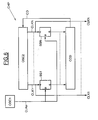
- the DDT detection device including a mode shown in FIG. 4, will make it possible to detect the presence or absence of a pulse in the signal, and in the event that a impulse is present, its instant of arrival and its polarity.
- This device can for example be incorporated into a TRM terminal of a local area network wireless communication system.
- this DDT device comprises, in the particular but non-limiting application which is illustrated here, a ANT antenna to receive the SGNR incident signal resulting from the transmission of the SGN signal on a transmission channel which can be multipath.
- the ANT antenna forms input means which deliver a SGB basic signal from the SGNR incident signal.
- the signal from base SGB is also an ultra band type pulse signal large.
- the shape of the PLSD pulses forming this SGB signal is illustrated in FIG. 3, and it differs from the shape of the PLS pulses illustrated in FIG. 2.
- the PLSD pulse is the theoretical response of the system upon receipt of a PLS pulse.
- this theoretical answer varies according to the characteristics of the means of reception.
- the basic signal SGB is then amplified in means low noise LNA amplification.
- the output signal from the LNA amplifier is then compared to a reference voltage Vref (for example the value zero) in a CMP comparator.
- the comparator CMP then delivers an intermediate signal SGI representative of the sign of the basic signal SGB, and therefore of the sign of the incident signal, with respect to the reference Vref.
- the intermediate signal SGI will then be sampled in MECH sampling means.
- These sampling means MECH will, as we will see in more detail below, issue successive groups of N samples. All of these samples go then be processed in digital processing means essentially comprising MCORR correlation means suitable for perform a correlation of the digital SNM signal delivered by the sampling means with a digital correlation signal predetermined SCR. The result of this correlation will allow detect the possible presence of a pulse.
- the center frequency of the signal pulses can be the order of several GHz, it is necessary that the frequency digital signal sampling rate is very high, i.e. higher for example at 10 GHz.
- a particularly simple way and easy to perform, to sample a signal at 10 GHz, can consist in using serial / parallel conversion means such as those illustrated in Figure 5.
- these series / parallel conversion means will successively deliver at a predetermined delivery frequency Fe, for example of the order of 200 MHz, groups of N samples in parallel, which will correspond to an effective sampling frequency of the intermediate signal equal to N.Fe.
- N can for example be chosen equal to 2 m , m being able to be equal to 7 for example, which then leads to obtaining groups of 128 samples.
- the effective sampling frequency will then be greater than 20 GHz.
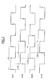
- these means of series / parallel conversion have a programmable CHP clock circuit receiving a signal CLKe base clock having frequency Fe and delivering N signals CLK1-CLKN elementary clock all having the same frequency Fe but mutually temporally offset by 1 / N.Fe. So, as indicative, these clock signals may be mutually temporally shifted by around 50 picoseconds, for example.
- the serial / parallel conversion means also include N flip-flops D, respectively referenced FF1-FFN. These flip-flops are respectively controlled by the N elementary clock signals CLK1-CLKN and they all receive the intermediate signal as input SGI from the CMP comparator.
- the intermediate signal SGI will therefore be sampled and the N successive samples will be stored in a signal-controlled LF output register CLKe basic clock.
- CLKe base clock At each rising edge of this signal CLKe base clock (rising edges spaced by a duration Te representing the period of this basic clock signal), the N samples will be delivered in parallel.
- the basic clock signal CLKe is one of the elementary clock signals, for example the signal CLK1.
- the programmable clock circuit CHP can be composed of a clock, for example a quartz, and a number delay elements connected in series at the output of the clock.
- the skilled person may possibly refer to the European patent application No. 0 843 418.
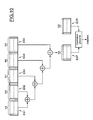
- the circuit CHP programmable clock includes a digital loop to phase lock including ( Figure 6) for example an oscillator OSC2 ring programmable, delivering the N clock signals elementary CLK1-CLKN.
- This ring oscillator is controlled at from a CCD control circuit, receiving the respective outputs of N scales BS1-BSN.
- These N flip-flops are respectively controlled by the N elementary clock signals CLK1-CLKN and receive on their input D the basic clock signal CLKe issued by example of a classic OSC1 quartz oscillator.
- the detection of the possible presence of an impulse will be carried out by a numerical correlation with a SCR reference correlation signal.
- N2 is much lower than N.
- the means of correlation will therefore first perform a first correlation (which is actually a term-to-term multiplication) between the N2 reference samples and the first N2 samples of the group of N samples delivered by the sampling means. This will give a first correlation value. Then, every ⁇ t, the N2 reference samples will shift by one sample so that get a new correlation value.
- the digital processing means will then detect the maximum among the correlation values, which will allow detect the presence and the moment of arrival of the pulse. Otherwise, according to the sign of this maximum value, we can determine the polarity of the pulse received. Alternatively, it is possible to detect only the passage by “0” of all the values of correlation.
- the digital processing means further perform a series of coherent integrations of the digital signal.
- Such integrations consistent are perfectly known per se to those skilled in the art.
- they can consist of summing homologous samples from several successive sets of N1 samples ES1-ES5, so as to obtain in final a final ESF set of N1 samples on which we are going perform the sliding correlation using the N2 samples of reference.
- the successive pulses are spaced irregularly over time (for example according to a known code)
- the summations of samples can take account of the shift time between pulses.
- the pulses of the incident signal were of known form.
- the invention also makes it possible to detect the presence of pulses an ultra-wideband pulse signal, whatever the form pulses even if the pulses are a priori of form unknown.
- the SCR reference correlation signal will be the digital signal itself.
- the means of MCORR correlation will autocorrelate the signal digital delivered by the sampling means.
- the detection of the correlation peak will detect the possible presence of pulses and the time difference between the pulses.
- this autocorrelation will be performed on two consecutive sets ES1 and ES2 of N1 samples of the digital signal.
- these N1 samples correspond to a length T of the signal window inside which the impulse is likely to be located.
- each sample is spaced by the distance ⁇ t.
- the means of sampling and the means of digital processing can be performed in CMOS technology, this which is significant in terms of manufacturing costs.
- this allows also to provide MCTL control means (FIG. 4) which may place the sampling means and / or the means of correlation in a waking state, for example during periods where the system knows it is not receiving a pulse, or during periods when the signal-to-noise ratio is not optimal. This allows significant energy savings.
- the correlation means can be produced by several correlators in parallel processing several groups of N samples, so as to obtain a processing speed compatible with the effective sampling frequency equal to N.Fe.
Abstract
Description
- un circuit d'horloge programmable recevant un signal d'horloge de base ayant la fréquence Fe et délivrant N signaux d'horloge élémentaires ayant tous la même fréquence Fe mais mutuellement temporellement décalés de 1/N.Fe,
- N bascules recevant en entrée le signal intermédiaire, respectivement commandées par les N signaux d'horloge élémentaires, et délivrant respectivement les N échantillons, et
- un registre de sortie commandé par le signal d'horloge de base pour stocker les N échantillons délivrés par les N bascules et les délivrer en parallèle à la fréquence de délivrance.
- la figure 1 illustre schématiquement un signal incident du type à bande ultra large ;
- la figure 2 illustre plus en détail l'une des impulsions du signal incident de la figure 1 ;
- la figure 3 illustre plus en détail l'une des impulsions du signal de base résultant de la réception du signal incident par le système de réception ;
- la figure 4 illustre schématiquement un mode de réalisation d'un dispositif de détection selon l'invention ;
- les figures 5 et 6 illustrent plus en détail mais toujours schématiquement un mode de réalisation des moyens d'échantillonnage du dispositif de la figure 4 ;
- la figure 7 représente un chronogramme temporel schématique des différents signaux d'horloge utilisés dans les moyens d'échantillonnage ;
- la figure 8 illustre un premier mode de réalisation et de mise en oeuvre de l'invention, utilisant un signal de corrélation de référence tel que par exemple celui illustré sur la figure 9 ;
- la figure 10 illustre schématiquement un deuxième mode de réalisation et de mise en oeuvre de l'invention, utilisant également un signal de corrélation de référence tel que celui illustré sur la figure 9 ; et
- les figures 11 et 12 illustrent deux autres modes de réalisation et de mise en oeuvre de l'invention.
- si, durant le second cycle, une transition d'état comparable est détectée dans le même intervalle, la commande de l'oscillateur en anneau n'est pas modifiée,
- si, durant le second cycle, une transition d'état comparable est détectée dans un intervalle ultérieur, la période de l'oscillateur en anneau est diminuée, et
- si, durant le second cycle, une transition d'état comparable est détectée dans un intervalle antérieur, la période de l'oscillateur en anneau est augmentée.
Claims (23)
- Procédé de détection des impulsions d'un signal incident impulsionnel du type à bande ultra large, comprenant une réception du signal incident (SGNR) de façon à obtenir un signal de base (SGB), un échantillonnage d'un signal intermédiaire (SGI) représentatif du signe du signal de base de façon à obtenir un signal numérique (SNM), et un traitement numérique du signal numérique comportant une corrélation du signal numérique (SNM) avec un signal de corrélation prédéterminé (SCR).
- Procédé selon la revendication 1, caractérisé par le fait que l'échantillonnage comporte une conversion série/parallèle de façon à délivrer successivement à une fréquence de délivrance prédéterminée Fe, des groupes de N échantillons en parallèle, ce qui correspond à une fréquence effective d'échantillonnage du signal intermédiaire (SGI) égale à N.Fe.
- Procédé selon la revendication 2, caractérisé par le fait que les impulsions (PLS) ont une fréquence centrale de quelques GHz, et par le fait que la fréquence effective d'échantillonnage est supérieure à 10GHz.
- Procédé selon la revendication 3, caractérisé par le fait que N est une puissance entière de 2, et par le fait que la fréquence effective d'échantillonnage est de l'ordre de 20GHz, la fréquence de délivrance Fe étant de l'ordre de 200MHz.
- Procédé selon l'une des revendications précédentes, caractérisé par le fait que le signal de corrélation (SCR) est le signal numérique.
- Procédé selon la revendication 5, caractérisé par le fait que les impulsions du signal incident sont respectivement contenues dans des fenêtres temporelles successives de longueur T, cette longueur correspondant à une fenêtre de N1 échantillons du signal numérique échantillonné, et par le fait que traitement numérique comporte une corrélation entre un premier ensemble de N1 échantillons du signal numérique (SNM) et un deuxième ensemble de N1 échantillons du signal numérique (SNM).
- Procédé selon l'une des revendications 1 à 4, caractérisé par le fait que le signal incident résulte de la transmission d'un signal impulsionnel initial comportant des impulsions de forme théorique connue, par le fait que le signal de corrélation (SCR) est un signal de corrélation de référence correspondant à un signal de base théorique issu de la réception d'une impulsion théorique (PLSD) ayant ladite forme théorique connue.
- Procédé selon la revendication 7, caractérisé par le fait que le signal numérique de référence (SCR) est formé de N2 échantillons de référence, et par le fait que traitement numérique comporte une corrélation glissante entre les échantillons du signal numérique et les N2 échantillons de référence.
- Procédé selon l'une des revendications précédentes, caractérisé par le fait que le traitement numérique comporte en outre une série d'intégrations cohérentes du signal numérique.
- Dispositif de détection des impulsions d'un signal incident impulsionnel du type à bande ultra large, comprenant des moyens d'entrée (ANT) pour recevoir le signal incident et délivrer un signal de base, des moyens de prétraitement (CMP) recevant le signal de base et aptes à délivrer un signal intermédiaire (SGI) représentatif du signe du signal de base par rapport à une référence, des moyens d'échantillonnage (MECH) du signal intermédiaire aptes à délivrer un signal numérique (SNM), et des moyens numériques de traitement aptes à effectuer une corrélation (MCORR) du signal numérique avec un signal de corrélation prédéterminé (SCR).
- Dispositif selon la revendication 10, caractérisé par le fait que les moyens d'échantillonnage (MECH) comportent des moyens de conversion série/parallèle aptes à délivrer successivement à une fréquence de délivrance prédéterminée Fe, des groupes de N échantillons en parallèle, ce qui correspond à une fréquence effective d'échantillonnage du signal intermédiaire égale à N.Fe.
- Dispositif selon la revendication 11, caractérisé par le fait que les moyens de conversion série/parallèle comportentun circuit d'horloge programmable (CHP) recevant un signal d'horloge de base (CLKe) ayant la fréquence Fe et délivrant N signaux d'horloge élémentaires (CLK1-CLKN) ayant tous la même fréquence Fe mais mutuellement temporellement décalés de 1/N.Fe,N bascules (FF1-FFN) recevant toutes en entrée le signal intermédiaire, respectivement commandées par les N signaux d'horloge élémentaires, et délivrant respectivement les N échantillons,un registre de sortie (BF) commandé par le signal d'horloge de base pour stocker les N échantillons délivrés par les N bascules et les délivrer en parallèle à la fréquence de délivrance.
- Dispositif selon la revendication 12, caractérisé par le fait que le circuit d'horloge programmable (CHP) comprend une boucle numérique à verrouillage de phase comportant un oscillateur programmable en anneau (OSC2) délivrant les N signaux d'horloge élémentaires et commandé à partir d'un circuit de commande (CCD) recevant les sorties respectives de N bascules (BS1-BSN) recevant toutes le signal d'horloge de base (CLKe) et respectivement commandées par les N signaux d'horloge élémentaires.
- Dispositif selon l'une des revendications 11 à 13, caractérisé par le fait que les impulsions ont une fréquence centrale de quelques GHz, et par le fait que la fréquence effective d'échantillonnage est supérieure à 10GHz.
- Dispositif selon la revendication 14, caractérisé par le fait que N est une puissance entière de 2, et par le fait que la fréquence effective d'échantillonnage est de l'ordre de 20GHz, la fréquence de délivrance Fe étant de l'ordre de 200MHz..
- Dispositif selon l'une des revendications 10 à 15, caractérisé par le fait que les moyens d'échantillonnage (MECH) sont réalisés en technologie CMOS.
- Dispositif selon la revendication 16, caractérisé par le fait qu'il comporte des moyens de contrôle (MCTL) aptes à placer les moyens d'échantillonnage et les moyens numériques de traitement dans un mode de veille au cours d'intervalles temporels prédéterminés.
- Dispositif selon l'une des revendications 10 à 17, caractérisé par le fait que le signal de corrélation (SCR) est le signal numérique.
- Dispositif selon la revendication 18, caractérisé par le fait que les impulsions du signal incident sont respectivement contenues dans des fenêtres temporelles successives de longueur T, cette longueur correspondant à une fenêtre de N1 échantillons du signal numérique délivré par les moyens d'échantillonnage, et par le fait que les moyens numériques de traitement effectuent une corrélation entre un premier ensemble de N1 échantillons du signal numérique (SNM) et un deuxième ensemble de N1 échantillons du signal numérique (SNM).
- Dispositif selon l'une des revendications 10 à 17, caractérisé par le fait que le signal incident résulte de la transmission d'un signal impulsionnel initial comportant des impulsions de forme théorique connue, par le fait que le signal de corrélation est un signal de corrélation de référence correspondant à un signal de base théorique issu de la réception d'une impulsion théorique (PLSD) ayant ladite forme théorique connue.
- Dispositif selon la revendication 20, caractérisé par le fait que le signal numérique de référence (SCR) est formé de N2 échantillons de référence, et par le fait que les moyens numériques de traitement effectuent une corrélation glissante entre les échantillons du signal numérique délivrés par les moyens d'échantillonnage et les N2 échantillons de référence.
- Dispositif selon l'une des revendications 18 à 21, caractérisé par le fait que les moyens numériques de traitement effectuent en outre une série d'intégrations cohérentes du signal numérique.
- Terminal d'un système de transmission sans fil, caractérisé par le fait qu'il incorpore un dispositif selon l'une des revendications 10 à 22.
Priority Applications (3)
| Application Number | Priority Date | Filing Date | Title |
|---|---|---|---|
| EP01402497A EP1298811A1 (fr) | 2001-09-27 | 2001-09-27 | Procédé et dispositif de détection des impulsions d'un signal incident impulsionnel du type à bande ultra large |
| JP2002278311A JP4315659B2 (ja) | 2001-09-27 | 2002-09-25 | 超広帯域タイプの入射パルス信号のパルスの検波方法及び検波装置 |
| US10/256,282 US7386066B2 (en) | 2001-09-27 | 2002-09-26 | Method and device for detecting pulses of an incident pulse signal of the ultra wideband type |
Applications Claiming Priority (1)
| Application Number | Priority Date | Filing Date | Title |
|---|---|---|---|
| EP01402497A EP1298811A1 (fr) | 2001-09-27 | 2001-09-27 | Procédé et dispositif de détection des impulsions d'un signal incident impulsionnel du type à bande ultra large |
Publications (1)
| Publication Number | Publication Date |
|---|---|
| EP1298811A1 true EP1298811A1 (fr) | 2003-04-02 |
Family
ID=8182900
Family Applications (1)
| Application Number | Title | Priority Date | Filing Date |
|---|---|---|---|
| EP01402497A Withdrawn EP1298811A1 (fr) | 2001-09-27 | 2001-09-27 | Procédé et dispositif de détection des impulsions d'un signal incident impulsionnel du type à bande ultra large |
Country Status (3)
| Country | Link |
|---|---|
| US (1) | US7386066B2 (fr) |
| EP (1) | EP1298811A1 (fr) |
| JP (1) | JP4315659B2 (fr) |
Cited By (5)
| Publication number | Priority date | Publication date | Assignee | Title |
|---|---|---|---|---|
| WO2004032442A1 (fr) * | 2002-10-01 | 2004-04-15 | Intel Corporation | Procede et appareil pour detecter et decoder les informations |
| WO2004091161A1 (fr) * | 2003-04-14 | 2004-10-21 | Koninklijke Philips Electronics N.V. | Detection d'impulsions dans des systemes de communications sans fil |
| EP1489802A2 (fr) * | 2003-06-18 | 2004-12-22 | Samsung Electronics Co., Ltd. | Système et procédé de transmission et réception pour modulation d'impulsions en position et modulation par déplacement de phase non-cohérente |
| EP1681819A1 (fr) | 2005-01-12 | 2006-07-19 | Commissariat A L'Energie Atomique | Système de communication multi antennes |
| US9083447B2 (en) | 2005-11-23 | 2015-07-14 | Commissariat A. L'energie Atomique | Receiver of pulses of an ultra wide band type signal and associated method |
Families Citing this family (11)
| Publication number | Priority date | Publication date | Assignee | Title |
|---|---|---|---|---|
| US20050031021A1 (en) * | 2003-07-18 | 2005-02-10 | David Baker | Communications systems and methods |
| GB2404123B (en) * | 2003-07-18 | 2005-07-27 | Artimi Ltd | Communications systems and methods |
| GB2404124B (en) * | 2003-07-18 | 2005-06-29 | Artimi Ltd | Communications systems and methods |
| US20050078735A1 (en) * | 2003-07-18 | 2005-04-14 | David Baker | Communications systems and methods |
| US7457350B2 (en) * | 2003-07-18 | 2008-11-25 | Artimi Ltd. | Communications systems and methods |
| US7342971B2 (en) * | 2003-09-16 | 2008-03-11 | Northrop Grumman Corporation | Bipolar waveform modulation for ultra wideband (UWB) communication networks |
| EP1553426A1 (fr) * | 2004-01-08 | 2005-07-13 | Institut de Microtechnique de l'Université de Neuchâtel | Procédé et dispositif récepteur pour communication de données sans fil par des signaux codés temporellement et à ultra-large bande |
| FR2881588B1 (fr) * | 2005-01-28 | 2007-04-27 | Groupe Ecoles Telecomm | Recepteur uwb et procede et systeme de transmission de donnees. |
| JP4774546B2 (ja) | 2005-03-24 | 2011-09-14 | 株式会社アドバンテスト | 測定装置、図形生成方法、プログラムおよび記録媒体 |
| JP4645342B2 (ja) * | 2005-07-26 | 2011-03-09 | パナソニック電工株式会社 | 無線受信装置及び無線受信方法 |
| KR101658933B1 (ko) * | 2015-02-27 | 2016-09-22 | 전자부품연구원 | 초광대역 수신기용 임펄스 캐리어 신호 복원기 및 그를 포함하는 초광대역 수신기 |
Citations (3)
| Publication number | Priority date | Publication date | Assignee | Title |
|---|---|---|---|---|
| US5677927A (en) * | 1994-09-20 | 1997-10-14 | Pulson Communications Corporation | Ultrawide-band communication system and method |
| US5832035A (en) * | 1994-09-20 | 1998-11-03 | Time Domain Corporation | Fast locking mechanism for channelized ultrawide-band communications |
| US5901172A (en) * | 1997-06-11 | 1999-05-04 | Multispectral Solutions, Inc. | Ultra wideband receiver with high speed noise and interference tracking threshold |
Family Cites Families (31)
| Publication number | Priority date | Publication date | Assignee | Title |
|---|---|---|---|---|
| US3588714A (en) * | 1969-06-30 | 1971-06-28 | Gen Motors Corp | System for reconstructing a digital signal |
| US3980945A (en) * | 1974-10-07 | 1976-09-14 | Raytheon Company | Digital communications system with immunity to frequency selective fading |
| US4359735A (en) * | 1980-11-06 | 1982-11-16 | The United States Of America As Represented By The Secretary Of The Navy | Multi-sampling-channel pulse compressor |
| US4426712A (en) * | 1981-05-22 | 1984-01-17 | Massachusetts Institute Of Technology | Correlation system for global position receiver |
| US4388646A (en) * | 1981-06-04 | 1983-06-14 | Rca Corporation | Low-distortion detection of pulses superimposed on an unknown and variable background signal |
| US4556760A (en) * | 1984-06-11 | 1985-12-03 | Itt Corporation | Hand-off filter for cellular mobile radio |
| US5371540A (en) * | 1990-04-19 | 1994-12-06 | Matsushita Electric Industrial Co. | Digital-signal-processing camera |
| KR940001220Y1 (ko) * | 1991-12-19 | 1994-03-07 | 주식회사 금성사 | 모터의 위상제어오차 제거필터 |
| US5347645A (en) * | 1991-12-26 | 1994-09-13 | The United States Of America As Represented By The Secretary Of The Navy | Time code interface |
| EP0609846B1 (fr) * | 1993-02-02 | 2000-03-22 | Honda Giken Kogyo Kabushiki Kaisha | Dispositif de contrôle des vibrations ou du bruit |
| NL9301026A (nl) * | 1993-06-11 | 1995-01-02 | Nederland Ptt | Optisch Ontvangsysteem. |
| US5490091A (en) * | 1994-03-01 | 1996-02-06 | Guzik Technical Enterprises, Inc. | Histograms of processed noise samples for measuring error rate of a PRML data detection channel |
| US5486830A (en) * | 1994-04-06 | 1996-01-23 | The United States Of America As Represented By The United States Department Of Energy | Radar transponder apparatus and signal processing technique |
| US5877802A (en) * | 1996-05-21 | 1999-03-02 | Asahi Kogaku Kogyo Kabushiki Kaisha | Video-signal processing device connectable to an electronic endoscope |
| US6028887A (en) * | 1996-07-12 | 2000-02-22 | General Electric Company | Power efficient receiver |
| US5982811A (en) * | 1996-07-12 | 1999-11-09 | General Electric Company | Method for efficient sampling in a correlator |
| JPH10112695A (ja) * | 1996-08-09 | 1998-04-28 | Ricoh Co Ltd | スペクトル拡散パルス位置変調通信方式 |
| SE507373C2 (sv) * | 1996-09-06 | 1998-05-18 | Ericsson Telefon Ab L M | Anordning och metod för pulsformning och effektförstärkning |
| US6097768A (en) * | 1996-11-21 | 2000-08-01 | Dps Group, Inc. | Phase detector for carrier recovery in a DQPSK receiver |
| SE514067C2 (sv) * | 1997-06-03 | 2000-12-18 | Leine & Linde Ab | Förfarande för fastställande av ett tillstånd i en givare, samt en givare med organ för tillståndsbedömning |
| JPH11160009A (ja) * | 1997-10-31 | 1999-06-18 | Samsung Heavy Ind Co Ltd | ストロークセンシングシリンダの絶対位置検出方法 |
| US6186949B1 (en) * | 1998-03-31 | 2001-02-13 | General Electric Company | Method and apparatus for three-dimensional flow imaging using coded excitation |
| US6210332B1 (en) * | 1998-03-31 | 2001-04-03 | General Electric Company | Method and apparatus for flow imaging using coded excitation |
| US6061134A (en) * | 1998-05-22 | 2000-05-09 | The United States Of America As Represented By The Administrator Of The National Aeronautics And Space Administration | Modulated Fourier Transform Raman fiber-optic spectroscopy |
| US6201986B1 (en) * | 1998-11-24 | 2001-03-13 | Mayo Foundation For Medical Education And Research | Synchronized K-space sampling in magnetic resonance angiography |
| US6456221B2 (en) * | 1999-10-28 | 2002-09-24 | The National University Of Singapore | Method and apparatus for signal detection in ultra wide-band communications |
| US6810087B2 (en) * | 2000-01-04 | 2004-10-26 | General Electric Company | Ultra-wideband communications system |
| US6354946B1 (en) * | 2000-09-20 | 2002-03-12 | Time Domain Corporation | Impulse radio interactive wireless gaming system and method |
| US6799193B2 (en) * | 2000-12-15 | 2004-09-28 | Maxim Integrated Products, Inc. | Fully digital symbol synchronization technique |
| EP1298812B1 (fr) * | 2001-09-27 | 2015-03-11 | STMicroelectronics S.A. | Procédé et dispositif de décodage d'un signal incident impulsionnel du type à bande ultra large, en particulier pour un système de communication sans fil. |
| US7397870B2 (en) * | 2002-06-07 | 2008-07-08 | Texas Instruments Incorporated | Ultra-wideband (UWB) receiver |
-
2001
- 2001-09-27 EP EP01402497A patent/EP1298811A1/fr not_active Withdrawn
-
2002
- 2002-09-25 JP JP2002278311A patent/JP4315659B2/ja not_active Expired - Fee Related
- 2002-09-26 US US10/256,282 patent/US7386066B2/en not_active Expired - Fee Related
Patent Citations (3)
| Publication number | Priority date | Publication date | Assignee | Title |
|---|---|---|---|---|
| US5677927A (en) * | 1994-09-20 | 1997-10-14 | Pulson Communications Corporation | Ultrawide-band communication system and method |
| US5832035A (en) * | 1994-09-20 | 1998-11-03 | Time Domain Corporation | Fast locking mechanism for channelized ultrawide-band communications |
| US5901172A (en) * | 1997-06-11 | 1999-05-04 | Multispectral Solutions, Inc. | Ultra wideband receiver with high speed noise and interference tracking threshold |
Non-Patent Citations (2)
| Title |
|---|
| DICKSON D ET AL: "An application specific integrated circuit implementation of a multiple correlator for UWB radio applications", MILCOM 1999. IEEE MILITARY COMMUNICATIONS. CONFERENCE PROCEEDINGS (CAT. NO.99CH36341), PROCEEDINGS OF CONFERENCE ON MILITARY COMMUNICATIONS (MILCOM'99), ATLANTIC CITY, NJ, USA, 31 OCT.-3 NOV. 1999, 1999, Piscataway, NJ, USA, IEEE, USA, pages 1207 - 1210 vol.2, XP010369820, ISBN: 0-7803-5538-5 * |
| WIN M Z ET AL: "ULTRA-WIDE BANDWIDTH TIME-HOPPING SPREAD-SPECTRUM IMPULSE RADIO FORWIRELESS MULTIPLE-ACCESS COMMUNICATIONS", IEEE TRANSACTIONS ON COMMUNICATIONS, IEEE INC. NEW YORK, US, vol. 48, no. 4, April 2000 (2000-04-01), pages 679 - 691, XP000932191, ISSN: 0090-6778 * |
Cited By (9)
| Publication number | Priority date | Publication date | Assignee | Title |
|---|---|---|---|---|
| WO2004032442A1 (fr) * | 2002-10-01 | 2004-04-15 | Intel Corporation | Procede et appareil pour detecter et decoder les informations |
| US7197062B2 (en) | 2002-10-01 | 2007-03-27 | Intel Corporation | Method and apparatus to detect and decode information |
| WO2004091161A1 (fr) * | 2003-04-14 | 2004-10-21 | Koninklijke Philips Electronics N.V. | Detection d'impulsions dans des systemes de communications sans fil |
| US8102905B2 (en) | 2003-04-14 | 2012-01-24 | St-Ericsson Sa | Pulse detection in wireless communications system |
| EP1489802A2 (fr) * | 2003-06-18 | 2004-12-22 | Samsung Electronics Co., Ltd. | Système et procédé de transmission et réception pour modulation d'impulsions en position et modulation par déplacement de phase non-cohérente |
| EP1489802A3 (fr) * | 2003-06-18 | 2006-06-28 | Samsung Electronics Co., Ltd. | Système et procédé de transmission et réception pour modulation d'impulsions en position et modulation par déplacement de phase non-cohérente |
| EP1681819A1 (fr) | 2005-01-12 | 2006-07-19 | Commissariat A L'Energie Atomique | Système de communication multi antennes |
| US7769072B2 (en) | 2005-01-12 | 2010-08-03 | Commissariat A L'energie Atomique | Multi-antenna communication system |
| US9083447B2 (en) | 2005-11-23 | 2015-07-14 | Commissariat A. L'energie Atomique | Receiver of pulses of an ultra wide band type signal and associated method |
Also Published As
| Publication number | Publication date |
|---|---|
| US20030086511A1 (en) | 2003-05-08 |
| US7386066B2 (en) | 2008-06-10 |
| JP2003179577A (ja) | 2003-06-27 |
| JP4315659B2 (ja) | 2009-08-19 |
Similar Documents
| Publication | Publication Date | Title |
|---|---|---|
| EP1298812B1 (fr) | Procédé et dispositif de décodage d'un signal incident impulsionnel du type à bande ultra large, en particulier pour un système de communication sans fil. | |
| EP1298811A1 (fr) | Procédé et dispositif de détection des impulsions d'un signal incident impulsionnel du type à bande ultra large | |
| US20030108133A1 (en) | Apparatus and method for increasing received signal-to-noise ratio in a transmit reference ultra-wideband system | |
| US7099422B2 (en) | Synchronization of ultra-wideband communications using a transmitted-reference preamble | |
| FR2918522A1 (fr) | Procede et dispositif de traitement d'un train d'impulsion d'un signal module, en particulier a signal a bande ultra large module par une modulation numerique par intervalles d'impulsions | |
| EP1706757B1 (fr) | Procede et dispositif recepteur pour communication de donnees sans fil par des signaux codes temporellement et a ultra-large bande | |
| EP2958245B1 (fr) | Récepteur uwb à poursuite robuste de dérive temporelle | |
| WO2018083070A1 (fr) | Procédé et dispositif récepteur pour l'estimation de l'instant d'arrivée d'un signal radio, procédé et système de localisation | |
| EP3039792B1 (fr) | Récepteur uwb à fonctionnement intermittent | |
| EP2012438B1 (fr) | Procédé et dispositif de corrélation d'un signal, en particulier un signal à bande ultra large. | |
| EP2506444B1 (fr) | Procédé d'intégration de signaux à impulsions à Ultra Large Bande (ULB) ainsi que dispositif pour la mise en oeuvre du procédé | |
| EP2938002B1 (fr) | Dispositif et méthode de détermination du temps d'arrivée d'un signal UWB | |
| EP1791266A1 (fr) | Récepteur d'impulsions d'un signal de type ultra large bande et procédé associé | |
| EP1573933B1 (fr) | Procede et systeme de reception d'un signal ultra-large bande a nombre de trajets de propagation auto-adaptatif | |
| EP1376149A1 (fr) | Procédé et dispositif de commande d'un générateur d'impulsions pour l'émission d'un signal impulsionnel du type à bande ultra large modulé en position | |
| EP1055940B1 (fr) | Procédé et système de mesure de la distance entre deux objets mettant en oeuvre des séquences pseudo-aleatoires orthogonales | |
| EP1455498A1 (fr) | Procédé et dispositif de génération d'impulsions à bande ultra large | |
| EP1842293B1 (fr) | Recepteur uwb et procede et systeme de transmission de donnees | |
| EP2146457A1 (fr) | Procédé de synchronisation temporelle d'un signal numérique, dispositif et produit programme d'ordinateur correspondants | |
| FR2979775A1 (fr) | Procede de synchronisation et de reception d'un recepteur radio, et recepteur adapte pour mettre en oeuvre un tel procede | |
| WO2005101666A1 (fr) | Dispositif de detection de signal ultra-large bande |
Legal Events
| Date | Code | Title | Description |
|---|---|---|---|
| PUAI | Public reference made under article 153(3) epc to a published international application that has entered the european phase |
Free format text: ORIGINAL CODE: 0009012 |
|
| AK | Designated contracting states |
Kind code of ref document: A1 Designated state(s): AT BE CH CY DE DK ES FI FR GB GR IE IT LI LU MC NL PT SE TR Designated state(s): AT BE CH CY DE DK ES FI FR GB GR IE IT LI LU MC NL PT SE TR |
|
| AX | Request for extension of the european patent |
Extension state: AL LT LV MK RO SI |
|
| 17P | Request for examination filed |
Effective date: 20030407 |
|
| 17Q | First examination report despatched |
Effective date: 20030916 |
|
| AKX | Designation fees paid |
Designated state(s): DE FR GB IT |
|
| APBK | Appeal reference recorded |
Free format text: ORIGINAL CODE: EPIDOSNREFNE |
|
| APBN | Date of receipt of notice of appeal recorded |
Free format text: ORIGINAL CODE: EPIDOSNNOA2E |
|
| APBR | Date of receipt of statement of grounds of appeal recorded |
Free format text: ORIGINAL CODE: EPIDOSNNOA3E |
|
| APAV | Appeal reference deleted |
Free format text: ORIGINAL CODE: EPIDOSDREFNE |
|
| APBT | Appeal procedure closed |
Free format text: ORIGINAL CODE: EPIDOSNNOA9E |
|
| STAA | Information on the status of an ep patent application or granted ep patent |
Free format text: STATUS: THE APPLICATION IS DEEMED TO BE WITHDRAWN |
|
| 18D | Application deemed to be withdrawn |
Effective date: 20150401 |