EP1298785A1 - Dispositif de commande d'un moteur à commutation électronique - Google Patents
Dispositif de commande d'un moteur à commutation électronique Download PDFInfo
- Publication number
- EP1298785A1 EP1298785A1 EP02292267A EP02292267A EP1298785A1 EP 1298785 A1 EP1298785 A1 EP 1298785A1 EP 02292267 A EP02292267 A EP 02292267A EP 02292267 A EP02292267 A EP 02292267A EP 1298785 A1 EP1298785 A1 EP 1298785A1
- Authority
- EP
- European Patent Office
- Prior art keywords
- rotor
- switching
- encoder
- signals
- control device
- Prior art date
- Legal status (The legal status is an assumption and is not a legal conclusion. Google has not performed a legal analysis and makes no representation as to the accuracy of the status listed.)
- Granted
Links
- 238000004804 winding Methods 0.000 claims abstract description 13
- 230000005405 multipole Effects 0.000 claims abstract description 7
- 238000000034 method Methods 0.000 claims description 13
- 238000001514 detection method Methods 0.000 claims description 11
- 230000006870 function Effects 0.000 claims description 11
- 230000003287 optical effect Effects 0.000 claims description 5
- 230000010363 phase shift Effects 0.000 claims description 5
- 101000860173 Myxococcus xanthus C-factor Proteins 0.000 claims description 3
- 230000005355 Hall effect Effects 0.000 claims description 2
- 230000009471 action Effects 0.000 claims description 2
- 230000008859 change Effects 0.000 claims description 2
- 238000005096 rolling process Methods 0.000 claims description 2
- 239000000523 sample Substances 0.000 claims description 2
- GNFTZDOKVXKIBK-UHFFFAOYSA-N 3-(2-methoxyethoxy)benzohydrazide Chemical compound COCCOC1=CC=CC(C(=O)NN)=C1 GNFTZDOKVXKIBK-UHFFFAOYSA-N 0.000 claims 1
- 230000001419 dependent effect Effects 0.000 claims 1
- 230000001276 controlling effect Effects 0.000 description 5
- 230000000737 periodic effect Effects 0.000 description 3
- 238000010586 diagram Methods 0.000 description 2
- 210000000056 organ Anatomy 0.000 description 2
- 230000001105 regulatory effect Effects 0.000 description 2
- 230000000630 rising effect Effects 0.000 description 2
- 238000012163 sequencing technique Methods 0.000 description 2
- 230000007704 transition Effects 0.000 description 2
- JBRZTFJDHDCESZ-UHFFFAOYSA-N AsGa Chemical compound [As]#[Ga] JBRZTFJDHDCESZ-UHFFFAOYSA-N 0.000 description 1
- 229910017214 AsGa Inorganic materials 0.000 description 1
- XUIMIQQOPSSXEZ-UHFFFAOYSA-N Silicon Chemical compound [Si] XUIMIQQOPSSXEZ-UHFFFAOYSA-N 0.000 description 1
- 238000011217 control strategy Methods 0.000 description 1
- 230000000694 effects Effects 0.000 description 1
- 238000005516 engineering process Methods 0.000 description 1
- 230000005669 field effect Effects 0.000 description 1
- 239000011521 glass Substances 0.000 description 1
- 230000010354 integration Effects 0.000 description 1
- 238000005259 measurement Methods 0.000 description 1
- 239000002184 metal Substances 0.000 description 1
- 229910052710 silicon Inorganic materials 0.000 description 1
- 239000010703 silicon Substances 0.000 description 1
- 238000004088 simulation Methods 0.000 description 1
- 239000000758 substrate Substances 0.000 description 1
- 238000003079 width control Methods 0.000 description 1
Images



Classifications
-
- H—ELECTRICITY
- H02—GENERATION; CONVERSION OR DISTRIBUTION OF ELECTRIC POWER
- H02P—CONTROL OR REGULATION OF ELECTRIC MOTORS, ELECTRIC GENERATORS OR DYNAMO-ELECTRIC CONVERTERS; CONTROLLING TRANSFORMERS, REACTORS OR CHOKE COILS
- H02P6/00—Arrangements for controlling synchronous motors or other dynamo-electric motors using electronic commutation dependent on the rotor position; Electronic commutators therefor
- H02P6/14—Electronic commutators
- H02P6/16—Circuit arrangements for detecting position
-
- B—PERFORMING OPERATIONS; TRANSPORTING
- B62—LAND VEHICLES FOR TRAVELLING OTHERWISE THAN ON RAILS
- B62D—MOTOR VEHICLES; TRAILERS
- B62D15/00—Steering not otherwise provided for
- B62D15/02—Steering position indicators ; Steering position determination; Steering aids
Definitions
- the invention relates to a device for controlling a switching motor electronics comprising P phases and N pairs of poles, a method of use of such a device and a bearing incorporating the encoder and the sensor of such a device. device.
- switching motors electronics or brushless motor, can be used to control the rotation of a mechanical organ in a large number of applications.
- a particular example of such an application is assistance to the management of motor vehicles by an electric power steering system.
- Document FR-2 749 452 discloses a control device of an electronically commutated electric motor that makes it possible to overcome some of the torque faults associated with switching the current of a phase to another.
- Such a control strategy therefore requires an additional sensor giving a high resolution position in addition to the one controlling the switching.
- the invention aims in particular to solve these drawbacks by proposing a switching device comprising a two-track coder movable in rotation and a single fixed rotating sensor which is able to deliver on the one hand current switching signals in the phases and secondly high resolution position signals for current control feeding the phases, and with a resolution fine enough to avoid motor torque modulations.
- the invention proposes a method of using such a device.
- control device in which the control signals enable, in function of a predetermined switching logic, to actuate the two by two switches alternately, the passage of the actuation of two switches to the following two being performed at each detection of a electrical pulse of the C signal.
- the invention relates to a device for controlling a switching motor electronic 1 or brushless motor comprising P phases.
- This type of motor typically comprises a rotor 2 carrying N pairs of poles magnetic North / South and a stator 3 carrying P coils B1-B3 formed respectively of a phase winding, the rotor 2 being rotated by known way by controlling the power supply in the P windings of phases.
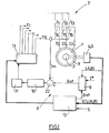
- FIG. 1 is a block diagram of a device for control of such a motor 1 to three phases and a pair of poles.
- the device comprises a circular multipolar encoder 4 intended to perform, together with the rotor 2, a plurality of revolutions around its axis of rotation.
- the encoder 4 comprises a main track 4a and a switching track 4b comprising 2 * P * N singularities 4b1-4b6 angularly dividedparts, the tracks 4a and switching 4b are arranged concentrically on the encoder 4.
- the encoder 4 is formed of a magnetic ring multipole on which is magnetized a plurality of pairs of North and South poles 5 equidistributed with a constant angular width so as to form the Main tracks 4a and 4b switching, a magnetic singularity 4b1-4b6 of the switching track 4b being formed of two pairs of poles which are different from others.
- the tracks main 4a, disposed towards the inside of the ring, and switching 4b, disposed towards the outside of the ring, comprise 24 pairs of poles.
- the pairs of poles 5 of the switching track 4b are in phase advance of a value ⁇ , for example equal to one eighth of a period, compared to those of the main track 4a.
- the switching track 4b comprises 6 singularities 4b1-4b6 magnetic spaced from two pairs of poles from each other.
- Each singularity is formed of two pairs of poles 5, the width of the poles being arranged so that they are respectively out of phase by ⁇ , 0, - ⁇ and 0 by relative to the corresponding poles of main runway 4a.
- each pulse of the signal C corresponds to the detection of a phase shift reversal between the main track 4a and the switching track 4b.
- the control device further comprises a fixed sensor 6 arranged in look and distance from air gap of the encoder 4.
- the sensor 6 comprises at least three sensitive elements of which at least two are positioned next to the main track 4a and at least one is positioned opposite the switching track 4b.
- the sensitive elements are chosen from the group comprising Hall effect probes, magnetoresistors, giant magnetoresistances.
- the sensor 6 used is capable of delivering two electrical signals S1, S2 periodic quadrature through sensitive elements arranged next to the main track 4a and an electrical signal S3 via sensitive elements arranged opposite the switching track 4b.
- sensors 6 comprising two sensitive elements that are able to to deliver the signals S1 and S2 are also known.
- the senor 6 further comprises an interpolator, for example of the type described in document FR-2 754 063 issued by Applicant, to increase the resolution of the output signals.
- the sensor 6 can be integrated on a silicon substrate or equivalent by example AsGa, so as to form an integrated and customized circuit for specific application, circuit sometimes referred to as ASIC to make reference to the integrated circuit designed partially or completely according to needs.
- the encoder 4 can be formed of a metal or glass target on which the tracks of reference and switching have been etched so as to form an optical pattern analogous to the multipole magnetic motif set out above, the elements Sensors are then formed of optical detectors.
- the control device further comprises a switching circuit 7 of the currents in the phase windings of the motor 1.
- the switching circuit 7 comprises 2 * P * N switches T1-T6, for example each formed of a MOSFET-type field effect transistor operating at 20 kHz, which are arranged in a bridge so as to feed the windings of phases appropriately.
- the 2 * P * N switches T1-T6 can be operated two by two next 2 * P * N possible states, the transition from one state to another being controlled by the detection of one of the 2 * P * N pulses TP1-TP6 of the C signal.
- the device for switching 7 includes 6 switches T1-T6 which allow to feed the three phase windings with respectively a current I1, I2 and I3, I1 + I2 + I3 being equal to 0.
- the current setpoint I * can be issued for example from a loop of speed control of the rotor 2, a control loop in position of the rotor 2 or a measurement of the torque to be applied by the rotor 2 on the mechanical organ.
- the setpoint I * is fed into an electronic circuit 9 which, from this setpoint, introduces a modulation of the setpoint Iref according to the position of the rotor resulting from the signals A and B, this modulation being of amplitude depending on I * and in phase opposition with respect to intrinsic torque modulation to the motor 1, in order to obtain a useful torque of the motor 1 without modulation.
- control circuit 8 comprises a regulation loop comprising a regulator 10, for example of the PID type (proportional integral derivative), a variable width control (PWM) 11 providing a square wave at 20 kHz whose duty cycle is controlled by the regulator 10 and a comparator 22 comparing Im to Iref from the circuit electronic 9.
- a regulator 10 for example of the PID type (proportional integral derivative)
- PWM variable width control
- the regulation loop makes it possible, from Iref, to modulate the current in the phase windings as a function of the position of the rotor 2 of so as to obtain a motor torque constantly equal to the setpoint I *.
- the control circuit 8 can be realized in the form of a single microprocessor 12 incorporating at least one switching logic of the circuit 7 which determines the sequence of the openings / closures of the different switches T1-T6.
- the regulation loop can be implemented in analog form.
- control circuit 8 comparing the current Im supplying the motor to the current setpoint Iref, modulates the current width and duration the switching signals through a logical function AND 13.
- the modulated switching signals in width and duration selectively closing two switches selected in the logic of switching so as to supply the two phase windings corresponding with the regulated current Im.
- Phase switching times may be provided during detection the rising or falling edge of the TP1-TP6 pulse.
- the rising edge is used in one direction of rotation and the falling edge in the other direction.
- Figures 4a and 4b show, in the context of the embodiment shown in FIG. 1, a switching logic of the coils, the sequencing of the switches T1-T6 and the current I1-I3 in the corresponding phases, respectively for rotation of the rotor 2 counterclockwise and hourly.
- the positions of the stator field are traveled according to the order b, a, f, e, d, c, b, etc ... with passage from one to the other of these positions by respectively detecting pulses TP4, TP3, TP2, TP1, TP6, TP5, TP4, etc ...
- the switching logic is performed so that the rotor field is out of phase with the stator field angle between 60 ° and 120 ° so as to optimize the torque provided by the motor 1.
- the signals A, B representative of the position of the rotor are used to measure the phase shift between the zero crossing of forces against electromotive motor 1 and the passage of reference pulses TP1-TP6.
- This phase shift value can be stored in a memory type EEPROM or flash of the control circuit 8 so, by registration, to allow detecting TP1-TP6 pulses at the desired switching positions.
- a method of using a controller is described below further comprising initialization means, for example integrated in the control device 8, the position of the rotor 2 making it possible to adapt the switching signals in the desired direction of rotation for the rotor 2.
- this method includes a procedure of initializing the position of the rotor 2 which comprises the steps envisaging first select a switching logic rotating the field stator in a sense.
- control circuit 8 is driven according to the first state of this logic to operate two switches T1-T6 for a given period of time to power two phases of the motor with a current linit sufficient to implement Rotating the rotor 2.
- the time can be typically 30 ms and the current linit must be chosen, for example by simulation, for, depending on the application considered, allow rotation of the rotor 2.
- the time can be optimized according to the inertia of the system.
- the determination of the case is made by analysis in the circuit of command 8 of the signals A, B.
- the first two cases do not allow to initialize the position of the rotor 2 because the linit initialization current has no effect (stator and rotor fields) in opposition of phase) either the rotor and stator fields will cross each other not when scrolling the states of the switching logic.
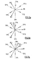
- the rotor field is initially in P1 position (see Figure 5b) and the switching logic induces anti rotation time of the stator field.
- the first state of this switching logic place the stator field in (a) which causes the rotation of the rotor 2 in the clockwise under the action of the torque induced by the angle formed between the fields rotor and stator.
- the second state of the switching logic (position b) induces a rotation of the rotor 2 in the same direction to the position P2 (see Figure 5c).
- the third state of the switching logic induces the stator field (c) which is in phase advance with respect to the P2 position which leads to a reversing the direction of rotation of the rotor 2.
- n-2 ie position (a)
- n-3 ie position (a)
- the initialization of the position of the rotor 2 allows, during the operation of the control device, to select the switching logic according the desired direction of rotation for the rotor 2, said direction S being injected into the circuit order 8.
- this procedure makes it possible to select the switching logic in depending on the desired direction of rotation for the rotor 2 while keeping a phase shift optimum between the stator and rotor fields.
- the encoder 4 is associated with the rotating ring 14 of a bearing 15 and the sensor 6 is associated with the fixed ring 16 of said bearing.
- the invention proposes a bearing 15 integrating the encoder 4 and the sensor 6 of the control device, said bearing being able to ensure the rotation of the rotor 2 or that of a member rotated by the rotor 2.
- the encoder 4 can be associated with the rotating ring 14 via a annular armature 17 on which the encoder 4 is overmolded.
- FIG. 6 represents an embodiment of the association of the sensor 6 with the fixed outer ring 16 of the bearing 15.
- the sensor 6 is associated with a support 18, for example of PCB type, carrying on the one hand the ASIC 19 and other part of the input / output connector 20 of the sensor 6.
- the ASIC 19 is positioned so that the sensitive elements are opposite and at a distance of encoder tracks 4.
- the input / output connector 20 is positioned in a housing 21 extending radially to the bearing 15.
Landscapes
- Engineering & Computer Science (AREA)
- Power Engineering (AREA)
- Chemical & Material Sciences (AREA)
- Combustion & Propulsion (AREA)
- Transportation (AREA)
- Mechanical Engineering (AREA)
- Control Of Motors That Do Not Use Commutators (AREA)
- Output Control And Ontrol Of Special Type Engine (AREA)
- Motor Or Generator Frames (AREA)
Abstract
Description
- au couple de réluctance du moteur ;
- aux défauts de commutation du courant d'une phase à l'autre en fonction de la vitesse de rotation du moteur ;
- à l'absence de chevauchement des FEM trapézoïdales.
- un codeur multipolaire circulaire destiné à effectuer, conjointement au rotor du moteur, une pluralité de tours autour de son axe de rotation, ledit codeur comprenant une piste multipolaire principale et une piste multipolaire de commutation comprenant 2*P*N singularités équiréparties angulairement, les pistes principale et de commutation étant concentriques sur le codeur ;
- un capteur fixe disposé en regard et à distance d'entrefer du codeur, comprenant au moins trois éléments sensibles dont au moins deux sont positionnés en regard de la piste principale de sorte à délivrer deux signaux électriques S1, S2 périodiques en quadrature et au moins un est positionné en regard de la piste de commutation de sorte à délivrer un signal électrique S3, le capteur comprenant un circuit électronique apte, à partir des signaux S1, S2 et S3, à délivrer des signaux digitaux A, B carrés en quadrature et C sous forme de 2*P*N impulsions par tour du codeur ;
- un circuit de commutation des courants dans les enroulements de phase du moteur comportant 2*P*N interrupteurs ;
- un circuit de commande du circuit de commutation qui :
- à partir du signal C fournit des signaux de commutation des interrupteurs ; et
- à partir des signaux A, B et en fonction d'une première consigne de courant définit une deuxième consigne de courant qui pilote le courant alimentant les enroulements de phase du moteur.
- est associé à la bague tournante un codeur multipolaire circulaire comprenant une piste multipolaire principale et une piste multipolaire de commutation comprenant 2*P*N singularités équiréparties angulairement, les pistes principale et de commutation étant concentriques sur le codeur ; et
- est associé à la bague fixe un capteur fixe disposé en regard et à distance d'entrefer du codeur, comprenant au moins trois éléments sensibles dont au moins deux sont positionnés en regard de la piste principale de sorte à délivrer deux signaux électriques A, B périodiques en quadrature et au moins un est positionné en regard de la piste de commutation de sorte à délivrer un signal électrique C sous forme de 2*P*N impulsions électriques par tour du codeur, le signal C étant destiné à fournir des signaux de commutation au moteur et les signaux A, B étant destinés, en fonction d'une première consigne de courant, à piloter le courant alimentant le moteur.
- la figure 1 est une représentation synoptique d'un dispositif de commande d'un moteur à commutation électronique comprenant 3 phases et une paire de pôles ;
- la figure 2 est une vue schématique de face d'un codeur utilisable dans le dispositif de commande de la figure 1 ;
- la figure 3 représente les signaux A, B et C délivrés par le capteur lors de la rotation du codeur représenté sur la figure 2 ;
- les figure 4a et 4b représentent un signal C, une logique de commutation commandée par ce signal, le séquencement des interrupteurs ainsi que le courant dans les phases correspondantes, respectivement pour une rotation dans le sens anti horaire et horaire du rotor ;
- la figure 5a représente sous forme vectorielle les positions relatives du champ statorique, du champ rotorique et des impulsions pour la logique de commutation des figures 4a et 4b ;
- les figures 5b et 5c, analogues à la figure 5a, représentent les étapes de la procédure d'initialisation de la position du rotor ;
- la figure 6 est une vue en coupe longitudinale d'un roulement suivant l'invention.
- à partir du signal C fournit des signaux de commutation de la pluralité d'interrupteurs T1-T6 ; et
- à partir des signaux A, B et en fonction d'une première consigne de courant I* définit une deuxième consigne de courant Iref qui pilote le courant Im alimentant les enroulements de phase du moteur 1.
- le moteur 1 est alimenté par un courant Im régulé par la boucle de régulation de sorte à permettre la mise en rotation du rotor 2 et donc celle du codeur 4 associé ;
- le capteur 6 délivre les signaux A, B représentatifs notamment de la position du rotor 2 et le signal C sous forme de 6 impulsions TP1-TP6 par tour ;
- à chaque détection d'une impulsion TP1-TP6, le microprocesseur 12 ferme sélectivement deux interrupteurs T1-T6 en fonction de la logique de commutation sélectionnée ;
- les signaux A, B, représentatifs notamment de la position du rotor 2, permettent, en fonction de la première consigne de courant I* et par l'intermédiaire du circuit de commande 8, le pilotage du courant Im alimentant le moteur 1 de sorte à limiter les modulations de celui-ci.
- pour une rotation anti horaire, on alimente le stator 3 de sorte à obtenir le champ statorique d puis le déroulement e, f, a, b, c, etc... est effectué à chaque détection d'une nouvelle impulsion TP1-TP6 ;
- pour une rotation horaire, on alimente le stator 3 de sorte à obtenir le champ statorique (a), la détection de TP3 induit le passage de (a) à (f) puis le déroulement e, d, c, b, a, etc...est effectué à chaque détection d'une nouvelle impulsion TP1-TP6.
Claims (17)
- Dispositif de commande d'un moteur à commutation électronique (1) comprenant P phases et N paires de pôles, ledit dispositif comprenant :un codeur multipolaire circulaire (4) destiné à effectuer, conjointement au rotor (2) du moteur (1), une pluralité de tours autour de son axe de rotation, ledit codeur (4) comprenant une piste multipolaire principale (4a) et une piste multipolaire de commutation (4b) comprenant 2*P*N singularités (4b1-4b6) équiréparties angulairement, les pistes principale (4a) et de commutation (4b) étant concentriques sur le codeur (4) ;un capteur fixe (6) disposé en regard et à distance d'entrefer du codeur (4), comprenant au moins trois éléments sensibles dont au moins deux sont positionnés en regard de la piste principale (4a) de sorte à délivrer deux signaux électriques S1, S2 périodiques en quadrature et au moins un est positionné en regard de la piste de commutation (4b) de sorte à délivrer un signal électrique S3, le capteur (6) comprenant un circuit électronique apte, à partir des signaux S1, S2 et S3, à délivrer des signaux digitaux A, B carrés en quadrature et C sous forme de 2*P*N impulsions (TP1-TP6) par tour du codeur;un circuit de commutation (7) des courants dans les enroulements de phase du moteur (1) comportant 2*P*N interrupteurs (T1-T6) ;un circuit de commande (8) du circuit de commutation (7) qui :à partir du signal C fournit des signaux de commutation des interrupteurs (T1-T6) ; età partir des signaux A, B et en fonction d'une première consigne de courant (I*) définit une deuxième consigne de courant (Iref) qui pilote le courant (Im) alimentant les enroulements de phase du moteur (1).
- Dispositif de commande selon la revendication 1, caractérisé en ce que le circuit de commande (8) comprend une boucle de régulation commandée par la deuxième consigne de courant (Iref) issue d'un circuit électronique (9), ledit circuit de commande (8) étant apte à moduler en largeur et en durée les signaux de commutation par l'intermédiaire d'une fonction logique ET (13).
- Dispositif de commande selon la revendication 1 ou 2, caractérisé en ce que le circuit de commande (8) comprend un microprocesseur (12) intégrant au moins une logique de commutation du circuit de commutation (7).
- Dispositif de commande selon l'une quelconque des revendications 1 à 3, caractérisé en ce que le codeur (4) est formé d'un anneau magnétique multipolaire sur lequel est aimantée une pluralité de paires de pôles (5) Nord et Sud équirépartis avec une largeur angulaire constante de sorte à former les pistes principale (4a) et de commutation (4b), une singularité magnétique (4b1-4b6) étant formée de deux paires de pôles qui sont différentes des autres.
- Dispositif de commande selon la revendication 4, caractérisé en ce que les éléments sensibles sont choisis parmi le groupe comprenant les sondes à effet Hall, les magnétorésistances, les magnétorésistances géantes.
- Dispositif de commande selon l'une quelconque des revendications 1 à 3, caractérisé en ce que le codeur (4) est formé d'une cible sur laquelle les pistes de référence (4a) et de commutation (4b) ont été gravées de sorte à former un motif optique analogue à un motif magnétique multipolaire, les éléments sensibles étant alors formés de détecteurs optiques.
- Dispositif de commande selon la revendication 5 ou 6, caractérisé en ce que le capteur (6) comprend une pluralité d'éléments sensibles alignés qui sont disposés en regard et à distance d'entrefer de la piste principale (4a).
- Dispositif de commande selon l'une quelconque des revendications 1 à 7, caractérisé en ce que le capteur (6) comprend un interpolateur augmentant la résolution des signaux de sortie.
- Dispositif de commande selon l'une quelconque des revendications 1 à 8, caractérisé en ce que le capteur (6) est intégré dans un circuit de type ASIC (19).
- Dispositif de commande selon l'une quelconque des revendications 1 à 9, caractérisé en ce que le codeur (4) est associé à la bague tournante (14) d'un roulement (15) permettant la rotation du rotor (2) ou celle d'un organe mis en rotation par le rotor (2).
- Dispositif de commande selon la revendication 10, caractérisé en ce que le capteur (6) est associé à la bague fixe (16) du roulement (15).
- Dispositif de commande selon la revendication 10, caractérisé en ce que le capteur (6) est dissocié de la bague fixe (16) du roulement (15).
- Dispositif de commande selon l'une quelconque des revendications 1 à 12, caractérisé en ce que le circuit de commande (8) comprend des moyens d'initialisation de la position du rotor (2) permettant d'adapter les signaux de commutation au sens de rotation voulu pour le rotor (2).
- Procédé d'utilisation d'un dispositif de commande selon l'une quelconque des revendications 1 à 13, dans lequel les signaux de commande permettent, en fonction d'une logique de commutation prédéterminée, d'actionner les interrupteurs (T1-T6) deux à deux alternativement, le passage de l'actionnement de deux interrupteurs (T1-T6) aux deux suivants s'effectuant à chaque détection d'une impulsion électrique (TP1-TP6) du signal C.
- Procédé selon la revendication 14, caractérisé en ce qu'il comprend une étape préalable d'indexation du codeur (4) dans laquelle le déphasage est mémorisé dans une mémoire de type EEPROM ou flash du circuit de commande (8).
- Procédé selon revendication 14 ou 15 lorsqu'elle dépend de la revendication 13, caractérisé en ce que, lors de la mise sous tension du dispositif, une procédure d'initialisation de la position du rotor (2) est effectuée, ladite procédure comprenant les étapes prévoyant de :ledit procédé permettant, en fonction du sens de rotation voulu pour le rotor (2), de sélectionner la logique de commutation correspondante.a) sélectionner une logique de commutation faisant tourner le champ statorique dans un sens ;b) piloter le circuit de commande (8) selon un premier état de cette logique afin d'actionner deux interrupteurs (T1-T6) pendant un laps de temps donné pour alimenter deux phases du moteur (1) avec un courant (linit) suffisant pour mettre en rotation le rotor (2) ;c) détecter, par analyse des signaux A, B, le sens de rotation du rotor (2) sous l'action de ce courant (linit) ;d) si le rotor (2) ne tourne pas, passer au deuxième état de la logique de commutation puis réitérer les étapes précédentes ;e) si le rotor (2) tourne dans le même sens que le champ statorique, changer la logique de commutation puis réitérer les étapes précédentes ;f) lorsque le rotor (2) tourne en sens inverse du champ statorique, réitérer les étapes b) et c) avec les états successifs de la logique de commutation jusqu'à inversion du sens de rotation du rotor (2) ;g) lors de l'inversion du sens de rotation du rotor (2), passer à l'état n-2 de la logique de commutation pour détecter une nouvelle inversion du sens de rotation du rotor (2) ;h) détecter la position de l'impulsion (TP1-TP6) du signal C enregistré lors de l'étape g) de sorte à obtenir la position relative du rotor (2) par rapport à cette impulsion ;
- Roulement (15) destiné à assurer la rotation du rotor (2) d'un moteur à commutation électronique (1) comprenant P phases et N paires de pôles (5) ou celle d'un organe mis en rotation par ledit rotor (2), ledit roulement (15) comprenant une bague fixe (16), une bague tournante (14) et des corps roulants disposés entre lesdites bagues (16, 14), dans lequel :est associé à la bague tournante (14) un codeur multipolaire circulaire (4) comprenant une piste multipolaire principale (4a) et une piste multipolaire de commutation (4b) comprenant 2*P*N singularités (4b1-4b6) équiréparties angulairement, les pistes principale (4a) et de commutation (4b) étant concentriques sur le codeur (4) ; etest associé à la bague fixe (16) un capteur (6) fixe disposé en regard et à distance d'entrefer du codeur (4), comprenant au moins trois éléments sensibles dont au moins deux sont positionnés en regard de la piste principale (4a) de sorte à délivrer deux signaux digitaux A, B carrés en quadrature et au moins un est positionné en regard de la piste de commutation (4b) de sorte à délivrer un signal C sous forme de 2*P*N impulsions (TP1-TP6) par tour du codeur (4), le signal C étant destiné à fournir des signaux de commutation au moteur (1) et les signaux A, B étant destinés, en fonction d'une consigne de courant (I*), à piloter le courant (Im) alimentant le moteur (1).
Applications Claiming Priority (2)
| Application Number | Priority Date | Filing Date | Title |
|---|---|---|---|
| FR0112381A FR2830140B1 (fr) | 2001-09-26 | 2001-09-26 | Dispositif de commande d'un moteur a commutation electronique |
| FR0112381 | 2001-09-26 |
Publications (2)
| Publication Number | Publication Date |
|---|---|
| EP1298785A1 true EP1298785A1 (fr) | 2003-04-02 |
| EP1298785B1 EP1298785B1 (fr) | 2018-03-07 |
Family
ID=8867626
Family Applications (1)
| Application Number | Title | Priority Date | Filing Date |
|---|---|---|---|
| EP02292267.8A Expired - Lifetime EP1298785B1 (fr) | 2001-09-26 | 2002-09-17 | Dispositif de commande d'un moteur à commutation électronique |
Country Status (5)
| Country | Link |
|---|---|
| US (1) | US6683427B2 (fr) |
| EP (1) | EP1298785B1 (fr) |
| JP (1) | JP2003134876A (fr) |
| BR (1) | BR0203934A (fr) |
| FR (1) | FR2830140B1 (fr) |
Cited By (4)
| Publication number | Priority date | Publication date | Assignee | Title |
|---|---|---|---|---|
| EP1298786A1 (fr) * | 2001-09-26 | 2003-04-02 | S.N.R. Roulements | Dispositif à commutation électronique commandé par impulsions |
| WO2011004115A1 (fr) | 2009-07-06 | 2011-01-13 | Renault Sas | Systeme de commande pour machine tournante a roulement instrumente |
| FR3035932A1 (fr) * | 2015-05-06 | 2016-11-11 | Skf Ab | Dispositif de roulement avec capteur integre |
| US20240375125A1 (en) * | 2022-09-27 | 2024-11-14 | Stratec Se | Centrifuge with safety shutter |
Families Citing this family (19)
| Publication number | Priority date | Publication date | Assignee | Title |
|---|---|---|---|---|
| EP1256164A2 (fr) * | 2000-02-09 | 2002-11-13 | Dana Corporation | Procede d'exploitation d'un generateur electrique commute a reaction |
| JP3674919B2 (ja) * | 2002-03-19 | 2005-07-27 | 本田技研工業株式会社 | 電動パワーステアリング装置とその制御方法 |
| JP4668196B2 (ja) * | 2003-09-19 | 2011-04-13 | ダイソン・テクノロジー・リミテッド | ローターアセンブリ |
| US7116075B2 (en) * | 2003-10-31 | 2006-10-03 | Valeo Electrical Systems, Inc. | Electric power steering system for a vehicle |
| US7276873B2 (en) | 2003-10-31 | 2007-10-02 | Valeo Electrical Systems, Inc. | Fault-handling system for electric power steering system |
| FR2862382B1 (fr) * | 2003-11-18 | 2006-06-02 | Roulements Soc Nouvelle | Systeme capteur de couple absolu de torsion et module le comprenant |
| US20050263330A1 (en) * | 2004-05-28 | 2005-12-01 | Valeo Electrical Systems, Inc. | Field-oriented control for brushless DC motor |
| FR2876972B1 (fr) * | 2004-10-25 | 2006-12-29 | Koyo Steering Europ K S E Soc | Procede pour la determination de la position angulaire du volant de conduite d'une direction assistee electrique de vehicule automobile |
| US7106020B1 (en) | 2005-08-30 | 2006-09-12 | Honeywell International Inc. | Method of operating a brushless DC motor |
| US7265512B2 (en) | 2005-08-30 | 2007-09-04 | Honeywell International Inc. | Actuator with feedback for end stop positioning |
| US7586279B2 (en) * | 2006-11-09 | 2009-09-08 | Honeywell International Inc. | Actuator position switch |
| US8084982B2 (en) * | 2008-11-18 | 2011-12-27 | Honeywell International Inc. | HVAC actuator with output torque compensation |
| US8084980B2 (en) * | 2009-01-30 | 2011-12-27 | Honeywell International Inc. | HVAC actuator with internal heating |
| US8525459B2 (en) * | 2010-07-15 | 2013-09-03 | Heidenhain Corporation | Code disk, optical encoder, and motor system |
| WO2012046122A1 (fr) * | 2010-10-05 | 2012-04-12 | Aktiebolaget Skf (Publ) | Unité de roulement pour couper et mettre le contact dans les automobiles et son procédé |
| CN102582740A (zh) * | 2012-03-15 | 2012-07-18 | 浙江工业大学 | 便携式电动滑板车 |
| WO2014060040A1 (fr) * | 2012-10-19 | 2014-04-24 | Aktiebolaget Skf | Système pour décaler un signal de sortie analogique d'un dispositif de capteur, unité de support de capteur et procédé de décalage |
| DE112013006365T5 (de) * | 2013-01-07 | 2015-10-08 | Aktiebolaget Skf | System zum Verschieben eines analogen Ausgangssignals einer Sensorvorrichtung, Sensorlagereinheit, Schiebermodul und Schiebeverfahren |
| JP6357996B2 (ja) * | 2014-09-12 | 2018-07-18 | アイシン精機株式会社 | インバータ装置 |
Citations (9)
| Publication number | Priority date | Publication date | Assignee | Title |
|---|---|---|---|---|
| EP0374805A2 (fr) * | 1988-12-18 | 1990-06-27 | Buck Werke GmbH & Co | Entraînement à moteur synchrone commuté électroniquement |
| FR2700588A1 (fr) * | 1993-01-19 | 1994-07-22 | Roulements Soc Nouvelle | Dispositif de montage à joint d'étanchéité à codeur incorporé. |
| FR2749452A1 (fr) * | 1996-06-04 | 1997-12-05 | Renault | Dispositif de commande de moteur electrique pour direction assistee |
| FR2754063A1 (fr) * | 1996-09-30 | 1998-04-03 | Roulements Soc Nouvelle | Circuit de multiplication de resolution et de determination de sens de deplacement |
| US5774068A (en) * | 1994-03-29 | 1998-06-30 | Tamagawa Seiki Kabushiki Kaisha | Absolute signal detecting method and absolute encoder |
| EP0871014A1 (fr) * | 1997-04-10 | 1998-10-14 | Snr Roulements | Codeur magnetique de generation d'impulsion de référence |
| FR2769088A1 (fr) * | 1997-09-26 | 1999-04-02 | Roulements Soc Nouvelle | Capteur digital de position relative |
| FR2792403A1 (fr) * | 1999-04-14 | 2000-10-20 | Roulements Soc Nouvelle | Capteur de position et/ou de deplacement comportant une pluralite d'elements sensibles alignes |
| FR2794504A1 (fr) * | 1999-06-04 | 2000-12-08 | Roulements Soc Nouvelle | Roulement equipe d'un dispositif capteur d'informations |
Family Cites Families (8)
| Publication number | Priority date | Publication date | Assignee | Title |
|---|---|---|---|---|
| US4365187A (en) * | 1980-05-15 | 1982-12-21 | Rotron Incorporated | Brushless D.C. motor |
| NZ236542A (en) * | 1990-12-19 | 1997-04-24 | Fisher & Paykel | Controlling application of power to windings of an electronically commutated motor |
| US5845045A (en) * | 1993-11-28 | 1998-12-01 | Papst-Motoren Gmbh & Co. Kg | Method and apparatus for DC motor speed control |
| US5590235A (en) * | 1993-12-03 | 1996-12-31 | Papst-Motoren Gmbh & Co. Kg | DC motor control with periodic reset |
| DE10033561B4 (de) * | 1999-07-14 | 2006-10-05 | Minebea Co., Ltd. | Elektronisch kommutierter Motor mit Kommutierungssignal |
| US6653829B1 (en) * | 1999-09-17 | 2003-11-25 | Delphi Technologies, Inc. | Low cost approach to measuring high resolution rotary position of electric machines |
| US6369535B1 (en) * | 2001-07-31 | 2002-04-09 | General Electric Company | Method and apparatus for current shaping in electronically commutated motors |
| FR2830139B1 (fr) * | 2001-09-26 | 2004-08-27 | Roulements Soc Nouvelle | Dispositif a commutation electronique commande par impulsions |
-
2001
- 2001-09-26 FR FR0112381A patent/FR2830140B1/fr not_active Expired - Lifetime
-
2002
- 2002-09-17 EP EP02292267.8A patent/EP1298785B1/fr not_active Expired - Lifetime
- 2002-09-26 JP JP2002281458A patent/JP2003134876A/ja active Pending
- 2002-09-26 US US10/255,039 patent/US6683427B2/en not_active Expired - Lifetime
- 2002-09-26 BR BR0203934-6A patent/BR0203934A/pt not_active IP Right Cessation
Patent Citations (9)
| Publication number | Priority date | Publication date | Assignee | Title |
|---|---|---|---|---|
| EP0374805A2 (fr) * | 1988-12-18 | 1990-06-27 | Buck Werke GmbH & Co | Entraînement à moteur synchrone commuté électroniquement |
| FR2700588A1 (fr) * | 1993-01-19 | 1994-07-22 | Roulements Soc Nouvelle | Dispositif de montage à joint d'étanchéité à codeur incorporé. |
| US5774068A (en) * | 1994-03-29 | 1998-06-30 | Tamagawa Seiki Kabushiki Kaisha | Absolute signal detecting method and absolute encoder |
| FR2749452A1 (fr) * | 1996-06-04 | 1997-12-05 | Renault | Dispositif de commande de moteur electrique pour direction assistee |
| FR2754063A1 (fr) * | 1996-09-30 | 1998-04-03 | Roulements Soc Nouvelle | Circuit de multiplication de resolution et de determination de sens de deplacement |
| EP0871014A1 (fr) * | 1997-04-10 | 1998-10-14 | Snr Roulements | Codeur magnetique de generation d'impulsion de référence |
| FR2769088A1 (fr) * | 1997-09-26 | 1999-04-02 | Roulements Soc Nouvelle | Capteur digital de position relative |
| FR2792403A1 (fr) * | 1999-04-14 | 2000-10-20 | Roulements Soc Nouvelle | Capteur de position et/ou de deplacement comportant une pluralite d'elements sensibles alignes |
| FR2794504A1 (fr) * | 1999-06-04 | 2000-12-08 | Roulements Soc Nouvelle | Roulement equipe d'un dispositif capteur d'informations |
Cited By (4)
| Publication number | Priority date | Publication date | Assignee | Title |
|---|---|---|---|---|
| EP1298786A1 (fr) * | 2001-09-26 | 2003-04-02 | S.N.R. Roulements | Dispositif à commutation électronique commandé par impulsions |
| WO2011004115A1 (fr) | 2009-07-06 | 2011-01-13 | Renault Sas | Systeme de commande pour machine tournante a roulement instrumente |
| FR3035932A1 (fr) * | 2015-05-06 | 2016-11-11 | Skf Ab | Dispositif de roulement avec capteur integre |
| US20240375125A1 (en) * | 2022-09-27 | 2024-11-14 | Stratec Se | Centrifuge with safety shutter |
Also Published As
| Publication number | Publication date |
|---|---|
| FR2830140A1 (fr) | 2003-03-28 |
| JP2003134876A (ja) | 2003-05-09 |
| US6683427B2 (en) | 2004-01-27 |
| FR2830140B1 (fr) | 2004-08-27 |
| US20030057903A1 (en) | 2003-03-27 |
| EP1298785B1 (fr) | 2018-03-07 |
| BR0203934A (pt) | 2004-01-06 |
Similar Documents
| Publication | Publication Date | Title |
|---|---|---|
| EP1298785B1 (fr) | Dispositif de commande d'un moteur à commutation électronique | |
| FR2829986A1 (fr) | Systeme de direction assistee electrique commande par impulsions | |
| EP1408603B1 (fr) | Dispositif de pilotage d'un moteur à commutation electronique au moyen d'un signal de position | |
| EP1323223B1 (fr) | Moto-reducteur commute sur un signal de position absolu | |
| EP1298786A1 (fr) | Dispositif à commutation électronique commandé par impulsions | |
| FR2811077A1 (fr) | Dispositif de determination de la position angulaire absolue d'un organe tournant | |
| WO2013164527A2 (fr) | Procede de determination du decalage angulaire entre le rotor et le stator d'une machine electrique d'un vehicule automobile | |
| FR2484167A1 (fr) | Circuit de commande d'arret pour un moteur a courant continu sans collecteur | |
| EP1398869B1 (fr) | Procédé et calculateur de détermination de la position angulaire à l'arrêt d'un rotor, unité de commande et système incorporant ce calculateur. | |
| EP1404016B1 (fr) | Dispositif de pilotage d'un moteur à commutation électronique comprenant des singularités réparties angulairement. | |
| FR3087597A1 (fr) | Machine electrique avec concentration de flux magnetique | |
| JP4084982B2 (ja) | ブラシレスモータの駆動装置及び駆動方法 | |
| FR2820252A1 (fr) | Systeme de controle de moteurs sans balais | |
| FR3083402A1 (fr) | Moteur electrique a courant continu sans balai et procede de commande associe | |
| EP0736963B1 (fr) | Procédé et dispositif de commande d'un moteur pas à pas | |
| FR2864722A1 (fr) | Procede d'exploitation d'informations de vitesse de rotation et de position de rotation d'un moteur a courant continu | |
| EP3815239B1 (fr) | Moteur electrique a courant continu sans balai et procede de commande associe | |
| FR2843248A1 (fr) | Procede de commande de fonctionnement synchronise d'au moins deux moteurs electriques polyphases | |
| EP0736964B1 (fr) | Système d'entraínement à base de moteur pas à pas comprenant des moyens perfectionnés de remise à zéro | |
| FR2755550A1 (fr) | Procede pour la commande en sens inverse d'un moteur electrique pas a pas, notamment de montre a aiguilles de tableau de bord de vehicule automobile | |
| FR2742943A1 (fr) | Procede et dispositif de commande d'un moteur electrique synchrone sans balai | |
| FR2895553A1 (fr) | Procede de pilotage electronique d'un moteur sans balais pour dispositif de defilement d'affiches publicitaires. | |
| JPS6328297A (ja) | リラクタンスモ−タの回転子位置検出装置 | |
| FR2707110A1 (fr) | Indicateur à curseur mobile et procédé d'utilisation de l'indicateur. | |
| FR3046308A1 (fr) | Procede de commande pseudo-sinusoidale d'un moteur electrique synchrone |
Legal Events
| Date | Code | Title | Description |
|---|---|---|---|
| PUAI | Public reference made under article 153(3) epc to a published international application that has entered the european phase |
Free format text: ORIGINAL CODE: 0009012 |
|
| AK | Designated contracting states |
Kind code of ref document: A1 Designated state(s): AT BE BG CH CY CZ DE DK EE ES FI FR GB GR IE IT LI LU MC NL PT SE SK TR |
|
| AX | Request for extension of the european patent |
Extension state: AL LT LV MK RO SI |
|
| 17P | Request for examination filed |
Effective date: 20030513 |
|
| AKX | Designation fees paid |
Designated state(s): AT BE BG CH CY CZ DE DK EE ES FI FR GB GR IE IT LI LU MC NL PT SE SK TR |
|
| 17Q | First examination report despatched |
Effective date: 20110421 |
|
| GRAP | Despatch of communication of intention to grant a patent |
Free format text: ORIGINAL CODE: EPIDOSNIGR1 |
|
| RIC1 | Information provided on ipc code assigned before grant |
Ipc: B62D 5/04 20060101ALI20170830BHEP Ipc: B62D 15/02 20060101ALI20170830BHEP Ipc: H02P 6/16 20160101AFI20170830BHEP |
|
| INTG | Intention to grant announced |
Effective date: 20171002 |
|
| GRAS | Grant fee paid |
Free format text: ORIGINAL CODE: EPIDOSNIGR3 |
|
| GRAA | (expected) grant |
Free format text: ORIGINAL CODE: 0009210 |
|
| AK | Designated contracting states |
Kind code of ref document: B1 Designated state(s): AT BE BG CH CY CZ DE DK EE ES FI FR GB GR IE IT LI LU MC NL PT SE SK TR |
|
| REG | Reference to a national code |
Ref country code: GB Ref legal event code: FG4D Free format text: NOT ENGLISH |
|
| REG | Reference to a national code |
Ref country code: CH Ref legal event code: EP Ref country code: AT Ref legal event code: REF Ref document number: 977566 Country of ref document: AT Kind code of ref document: T Effective date: 20180315 |
|
| REG | Reference to a national code |
Ref country code: IE Ref legal event code: FG4D Free format text: LANGUAGE OF EP DOCUMENT: FRENCH |
|
| REG | Reference to a national code |
Ref country code: DE Ref legal event code: R096 Ref document number: 60249332 Country of ref document: DE |
|
| REG | Reference to a national code |
Ref country code: NL Ref legal event code: MP Effective date: 20180307 |
|
| PG25 | Lapsed in a contracting state [announced via postgrant information from national office to epo] |
Ref country code: CY Free format text: LAPSE BECAUSE OF FAILURE TO SUBMIT A TRANSLATION OF THE DESCRIPTION OR TO PAY THE FEE WITHIN THE PRESCRIBED TIME-LIMIT Effective date: 20180307 Ref country code: ES Free format text: LAPSE BECAUSE OF FAILURE TO SUBMIT A TRANSLATION OF THE DESCRIPTION OR TO PAY THE FEE WITHIN THE PRESCRIBED TIME-LIMIT Effective date: 20180307 Ref country code: FI Free format text: LAPSE BECAUSE OF FAILURE TO SUBMIT A TRANSLATION OF THE DESCRIPTION OR TO PAY THE FEE WITHIN THE PRESCRIBED TIME-LIMIT Effective date: 20180307 |
|
| REG | Reference to a national code |
Ref country code: AT Ref legal event code: MK05 Ref document number: 977566 Country of ref document: AT Kind code of ref document: T Effective date: 20180307 |
|
| PG25 | Lapsed in a contracting state [announced via postgrant information from national office to epo] |
Ref country code: SE Free format text: LAPSE BECAUSE OF FAILURE TO SUBMIT A TRANSLATION OF THE DESCRIPTION OR TO PAY THE FEE WITHIN THE PRESCRIBED TIME-LIMIT Effective date: 20180307 Ref country code: GR Free format text: LAPSE BECAUSE OF FAILURE TO SUBMIT A TRANSLATION OF THE DESCRIPTION OR TO PAY THE FEE WITHIN THE PRESCRIBED TIME-LIMIT Effective date: 20180608 Ref country code: BG Free format text: LAPSE BECAUSE OF FAILURE TO SUBMIT A TRANSLATION OF THE DESCRIPTION OR TO PAY THE FEE WITHIN THE PRESCRIBED TIME-LIMIT Effective date: 20180607 |
|
| REG | Reference to a national code |
Ref country code: FR Ref legal event code: PLFP Year of fee payment: 17 |
|
| PG25 | Lapsed in a contracting state [announced via postgrant information from national office to epo] |
Ref country code: NL Free format text: LAPSE BECAUSE OF FAILURE TO SUBMIT A TRANSLATION OF THE DESCRIPTION OR TO PAY THE FEE WITHIN THE PRESCRIBED TIME-LIMIT Effective date: 20180307 Ref country code: IT Free format text: LAPSE BECAUSE OF FAILURE TO SUBMIT A TRANSLATION OF THE DESCRIPTION OR TO PAY THE FEE WITHIN THE PRESCRIBED TIME-LIMIT Effective date: 20180307 Ref country code: EE Free format text: LAPSE BECAUSE OF FAILURE TO SUBMIT A TRANSLATION OF THE DESCRIPTION OR TO PAY THE FEE WITHIN THE PRESCRIBED TIME-LIMIT Effective date: 20180307 |
|
| PG25 | Lapsed in a contracting state [announced via postgrant information from national office to epo] |
Ref country code: SK Free format text: LAPSE BECAUSE OF FAILURE TO SUBMIT A TRANSLATION OF THE DESCRIPTION OR TO PAY THE FEE WITHIN THE PRESCRIBED TIME-LIMIT Effective date: 20180307 Ref country code: CZ Free format text: LAPSE BECAUSE OF FAILURE TO SUBMIT A TRANSLATION OF THE DESCRIPTION OR TO PAY THE FEE WITHIN THE PRESCRIBED TIME-LIMIT Effective date: 20180307 Ref country code: AT Free format text: LAPSE BECAUSE OF FAILURE TO SUBMIT A TRANSLATION OF THE DESCRIPTION OR TO PAY THE FEE WITHIN THE PRESCRIBED TIME-LIMIT Effective date: 20180307 |
|
| REG | Reference to a national code |
Ref country code: DE Ref legal event code: R097 Ref document number: 60249332 Country of ref document: DE |
|
| PG25 | Lapsed in a contracting state [announced via postgrant information from national office to epo] |
Ref country code: PT Free format text: LAPSE BECAUSE OF FAILURE TO SUBMIT A TRANSLATION OF THE DESCRIPTION OR TO PAY THE FEE WITHIN THE PRESCRIBED TIME-LIMIT Effective date: 20180709 |
|
| PLBE | No opposition filed within time limit |
Free format text: ORIGINAL CODE: 0009261 |
|
| STAA | Information on the status of an ep patent application or granted ep patent |
Free format text: STATUS: NO OPPOSITION FILED WITHIN TIME LIMIT |
|
| PG25 | Lapsed in a contracting state [announced via postgrant information from national office to epo] |
Ref country code: DK Free format text: LAPSE BECAUSE OF FAILURE TO SUBMIT A TRANSLATION OF THE DESCRIPTION OR TO PAY THE FEE WITHIN THE PRESCRIBED TIME-LIMIT Effective date: 20180307 |
|
| 26N | No opposition filed |
Effective date: 20181210 |
|
| REG | Reference to a national code |
Ref country code: DE Ref legal event code: R119 Ref document number: 60249332 Country of ref document: DE |
|
| PG25 | Lapsed in a contracting state [announced via postgrant information from national office to epo] |
Ref country code: MC Free format text: LAPSE BECAUSE OF FAILURE TO SUBMIT A TRANSLATION OF THE DESCRIPTION OR TO PAY THE FEE WITHIN THE PRESCRIBED TIME-LIMIT Effective date: 20180307 |
|
| REG | Reference to a national code |
Ref country code: CH Ref legal event code: PL |
|
| GBPC | Gb: european patent ceased through non-payment of renewal fee |
Effective date: 20180917 |
|
| REG | Reference to a national code |
Ref country code: BE Ref legal event code: MM Effective date: 20180930 |
|
| REG | Reference to a national code |
Ref country code: IE Ref legal event code: MM4A |
|
| PG25 | Lapsed in a contracting state [announced via postgrant information from national office to epo] |
Ref country code: LU Free format text: LAPSE BECAUSE OF NON-PAYMENT OF DUE FEES Effective date: 20180917 |
|
| PG25 | Lapsed in a contracting state [announced via postgrant information from national office to epo] |
Ref country code: IE Free format text: LAPSE BECAUSE OF NON-PAYMENT OF DUE FEES Effective date: 20180917 Ref country code: DE Free format text: LAPSE BECAUSE OF NON-PAYMENT OF DUE FEES Effective date: 20190402 |
|
| PG25 | Lapsed in a contracting state [announced via postgrant information from national office to epo] |
Ref country code: LI Free format text: LAPSE BECAUSE OF NON-PAYMENT OF DUE FEES Effective date: 20180930 Ref country code: CH Free format text: LAPSE BECAUSE OF NON-PAYMENT OF DUE FEES Effective date: 20180930 Ref country code: BE Free format text: LAPSE BECAUSE OF NON-PAYMENT OF DUE FEES Effective date: 20180930 |
|
| PG25 | Lapsed in a contracting state [announced via postgrant information from national office to epo] |
Ref country code: GB Free format text: LAPSE BECAUSE OF NON-PAYMENT OF DUE FEES Effective date: 20180917 |
|
| PG25 | Lapsed in a contracting state [announced via postgrant information from national office to epo] |
Ref country code: TR Free format text: LAPSE BECAUSE OF FAILURE TO SUBMIT A TRANSLATION OF THE DESCRIPTION OR TO PAY THE FEE WITHIN THE PRESCRIBED TIME-LIMIT Effective date: 20180307 |
|
| PGFP | Annual fee paid to national office [announced via postgrant information from national office to epo] |
Ref country code: FR Payment date: 20200914 Year of fee payment: 19 |
|
| PG25 | Lapsed in a contracting state [announced via postgrant information from national office to epo] |
Ref country code: FR Free format text: LAPSE BECAUSE OF NON-PAYMENT OF DUE FEES Effective date: 20210930 |