EP1298513A2 - Monitoring device and monitoring method for vacuum device - Google Patents
Monitoring device and monitoring method for vacuum device Download PDFInfo
- Publication number
- EP1298513A2 EP1298513A2 EP02021694A EP02021694A EP1298513A2 EP 1298513 A2 EP1298513 A2 EP 1298513A2 EP 02021694 A EP02021694 A EP 02021694A EP 02021694 A EP02021694 A EP 02021694A EP 1298513 A2 EP1298513 A2 EP 1298513A2
- Authority
- EP
- European Patent Office
- Prior art keywords
- vacuum
- data
- constituent parts
- screen display
- vacuum system
- Prior art date
- Legal status (The legal status is an assumption and is not a legal conclusion. Google has not performed a legal analysis and makes no representation as to the accuracy of the status listed.)
- Granted
Links
Images





Classifications
-
- G—PHYSICS
- G05—CONTROLLING; REGULATING
- G05B—CONTROL OR REGULATING SYSTEMS IN GENERAL; FUNCTIONAL ELEMENTS OF SUCH SYSTEMS; MONITORING OR TESTING ARRANGEMENTS FOR SUCH SYSTEMS OR ELEMENTS
- G05B23/00—Testing or monitoring of control systems or parts thereof
- G05B23/02—Electric testing or monitoring
- G05B23/0205—Electric testing or monitoring by means of a monitoring system capable of detecting and responding to faults
- G05B23/0218—Electric testing or monitoring by means of a monitoring system capable of detecting and responding to faults characterised by the fault detection method dealing with either existing or incipient faults
- G05B23/0224—Process history based detection method, e.g. whereby history implies the availability of large amounts of data
- G05B23/024—Quantitative history assessment, e.g. mathematical relationships between available data; Functions therefor; Principal component analysis [PCA]; Partial least square [PLS]; Statistical classifiers, e.g. Bayesian networks, linear regression or correlation analysis; Neural networks
-
- H—ELECTRICITY
- H10—SEMICONDUCTOR DEVICES; ELECTRIC SOLID-STATE DEVICES NOT OTHERWISE PROVIDED FOR
- H10P—GENERIC PROCESSES OR APPARATUS FOR THE MANUFACTURE OR TREATMENT OF DEVICES COVERED BY CLASS H10
- H10P74/00—Testing or measuring during manufacture or treatment of wafers, substrates or devices
Definitions
- the present invention relates to a monitoring method and a monitoring device of a vacuum-system device having a vacuum portion such as a length-measuring SEM (Scanning Electron Microscope) or a semiconductor manufacturing device having a vacuum processing device (hereinafter referred to as "vacuum device").
- a vacuum-system device having a vacuum portion such as a length-measuring SEM (Scanning Electron Microscope) or a semiconductor manufacturing device having a vacuum processing device (hereinafter referred to as "vacuum device”).
- a dedicated measuring device or a dedicated vacuum gauge is connected to the vacuum device and the monitoring of the state of the inside of the vacuum device is performed each time when the monitoring is necessary.
- the present invention has been made in view of the above and it is an object of the present invention to provide a monitoring device and a method which can simply and collectively perform the maintenance control of the device or counter measures to overcome drawbacks by providing a monitoring method equivalent to monitoring in real time and simultaneously based on data from respective types of sensors of the vacuum device.
- the present invention provides a monitoring device of a vacuum device having a vacuum system comprising a screen display device, a screen display processing device which receives operation information signals from the vacuum system as input data and performs screen display processing so as to make the screen display device perform a screen display, and a memory device which stores basic monitoring data and operation history data of a plurality of constituent parts which constitute the vacuum system, wherein on a screen of the screen display device, the basic monitoring data and the operation history data of the plurality of constituent parts are displayed as timing charts which progress simultaneously in comparison, and a display which designates simultaneous time positions over a plurality of constituent parts of the vacuum system on the timing charts is performed.
- the present invention further provides amonitoring device of a vacuum device having a vacuum system comprising a screen display device, a screen display processing device which receives operation information signals from the vacuum system as input data and performs screen display processing so as to make the screen display device perform a screen display, and a memory device which stores basic monitoring data and operation history data of a plurality of constituent parts which constitute the vacuum system, wherein on a screen of the screen display device, the plurality of constituent parts are displayed, and the basic monitoring data and the operation history data of the constituent parts are displayed as timing charts which progress simultaneously in comparison, and when simultaneous time positions are designated extending over the plurality of constituent parts of the vacuum system on the timing charts, operation states of the constituent parts which correspond to the positions are displayed together.
- the present invention still further provides a monitoring device of a vacuum device having a vacuum system comprising a screen display device, a screen display processing device which receives operation information signals from the vacuum system as input data and performs screen display processing so as to make the screen display device perform a screen display, and a memory device which stores basic monitoring data and operation history data of a plurality of constituent parts which constitute the vacuum system and a predetermined difference between the basic monitoring data and the operation history data, and a processing device which compares the basic monitoring data and the operation history data of the plurality of constituent parts as timing charts which progress simultaneously, and judges whether any one of the plurality of constituent parts exceeds the difference at the designated simultaneous time.
- the present invention still further provides a monitoring device of a vacuum device having a vacuum system which produces a vacuum comprising a screen display device, a screen display processing device which receives operation information signals from the vacuum system as input data and performs screen display processing so as to make the screen display device perform a screen display, and a memory device which stores basic monitoring data and operation history data of a plurality of constituent parts which constitute the vacuum system and a predetermined difference between the basic monitoring data and the operation history data, and a processing device which compares the basic monitoring data and the operation history data of the constituent parts as timing charts which progress simultaneously, and judges whether any one of the plurality of constituent parts exceeds the difference at the designated simultaneous time, wherein on a screen of the screen display device, the plurality of constituent parts are displayed, and the basic monitoring data and the operation history data of the constituent parts are displayed as timing charts which progress simultaneously in comparison, and when simultaneous time positions are designated extending over the plurality of constituent parts of the vacuum system on the timing charts, operation states of the constituent parts which correspond to the positions are displayed together.
- the present invention still further provides a monitoring method of a vacuum device having a vacuum system which produces a vacuum comprising a step in which operation information signals from the vacuum system are inputted as data and screen display processing is performed, a step in which basic monitoring data and operation history data of a plurality of constituent parts which constitute the vacuum system are stored, a step in which the basic monitoring data and the operation history data of the plurality of constituent parts are displayed on a screen of the screen display device as timing charts which progress simultaneously in comparison, and a step in which a display which designates simultaneous time positions extending over the plurality of constituent parts of the vacuum system on the timing chart is performed.
- the present invention still further provides a monitoring method of a vacuum device which has a vacuum system producing a vacuum and is installed at a remote place being characterized in that operation information signals from the vacuum system of the vacuum device which is preliminarily determined by a contract are inputted as data and screen display processing is performed, basic monitoring data and operation history data of a plurality of constituent parts which constitute the vacuum system are stored, with respect to the vacuum device, the constituent parts are sequentially displayed on a screen of the screen display device, and the basic monitoring data and the operation history data of the plurality of constituent parts are displayed as timing charts which progress simultaneously in comparison, and when simultaneous time positions are designated extending over the plurality of constituent parts of the vacuum system on the timing charts, operation states of the constituent parts which correspond to the positions are reported.
- the present invention still further provides a monitoring method of a vacuum device which has a vacuum system producing a vacuum being characterized in that operation information signals from the vacuum system of the vacuum device which is preliminarily determined by a contract are inputted as data through a communication network and screen display processing is performed, basic monitoring data and operation history data of a plurality of constituent parts which constitute the vacuum system are stored, with respect to the vacuum device, the constituent parts are sequentially displayed on a screen of the screen display device, and the basic monitoring data and the operation history data of the plurality of constituent parts are displayed as timing charts which progress simultaneously in comparison, and when simultaneous time positions are designated extending over the plurality of constituent parts of the vacuum system on the timing charts, operation states of the constituent parts which correspond to the positions are displayed, and a period necessary for the difference between the basic monitoring data and the operation history data to reach a predetermined difference is predicted based on the state of the difference between the basic monitoring data and the operation history data from the timing charts which progress simultaneously every contract and next maintenance time is reported.
- the explanation is made by taking a length-measuring SEM as an example hereinafter.
- the present invention is applicable to any vacuum device having a vacuum portion.
- Fig. 1 shows a constitution of a length-measuring system according to length-measuring SEM which constitute an embodiment of this invention
- Fig. 2 shows the constitution of an electro-optic system which performs the function of the length-measuring SEM.
- a length-measuring system 100 is constituted of an atmosphere transport system having an atmosphere transport part 10, a vacuum system having a sample transport and measuring part 11, and a display viewing and manipulation system having an imaging part 12.
- the atmosphere transport part 10 includes a cassette (that is, hoop) 15 which accommodates and holds a plurality of substrates constituting a plurality of samples, a cassette base 16 and a transport device 17 having an arm which is extended into the inside of the cassette 15 for performing loading and unloading of the substrates.
- the transport device 17 is constituted of a robot for transporting and is arranged either in vacuum or in a controlled atmosphere.
- the robot includes a moving portion which moves in the X axis direction, the Y axis direction and the Z axis direction and is rotatable in the horizontal direction.
- the above-mentioned arm can be extended into a load lock chamber 19.
- the sample transport and length-measuring part 11 includes a transport body 18, the above-mentioned load lock chamber (may be also referred to as "double load lock chamber” ) 19, a transport chamber 20 and a measuring chamber 21(sample chamber).
- Vacuum producing devices 22, 23 are respectively connected to the transport chamber 20 and the measuring chamber 21 so that the transport chamber 20 and the measuring chamber 21 can be controlled in vacuum or under a controlled atmospheric pressure.
- the vacuum producing devices 22, 23 are controlled by a vacuum producing control device having an exhaust system (not shown in the drawing).
- an electro-optic mirror body 30 is arranged in the measuring chamber 21.
- a sample base 31 and a sample stage 32 for controlling and fixing the sample base 31 are disposed.
- a CCD camera 35 having an optical microscope is arranged parallel to the electro-optic mirror body 30.
- the electro-optic mirror body 30 which constitutes the length-measuring system 100 includes, as has been well known, an electro-optic system (lens-barrel portion), a sample chamber, an exhaust system, and a display viewing/manipulation system.
- the electro-optic system is constituted of a filament power source 40 and a filament 41 which constitute an electron gun generating accelerated electrons, a lens system which focuses a bundle 39 of accelerated electrons (primary electron beams) and converges the bundle 39, and a detector 47 (SE/BSE) which detects secondary electrons generated from the sample or the like.
- the electron gun is a portion which constitutes a source for generating accelerated electrons having certain energies.
- a condenser lens 43 (focusing lens) is constituted of a pull-out electrode and an anode and accelerating voltages are applied to a cathode using an accelerating voltage source 44.
- a focusing lens, an object lens, an object lens stop, a scanning coil, an astigmatism correction device 42 and the like are mounted.
- numeral 45 indicates an object lens
- numeral 48 indicates an EXB filter.
- a booster voltage source 49 for applying voltage is connected to the object lens 45.
- the detector 47 is a device for detecting the secondary electrons and reflection electrons 46.
- the secondary electrons exhibit low energy, the secondary electrons are collected by a collector and are converted into photo electrons by a scintillator and are subjected to signal amplification by a photo electron amplifier tube. To detect the reflected electrons, the scintillator or semiconductor type is used.
- a sample base is installed in the measuring chamber which constitutes the sample chamber and a base material (sample) 50 such as wafer is placed on the sample base. Further, a sample stage, a sample loading device, a spectroscope for X ray detection and the like are mounted on the sample base. A retarding voltage source 51 for applying voltage is mounted on the base material 50.
- the sample stage has functions of moving in the X, Y and Z directions rotating and tilting.
- a rotary pump, an oil diffusion pump or the like can be used as an exhaust device of the vacuum system.
- the display viewing/manipulation system displays a secondary electron image, a reflection electron image, an X ray image and the like on the imaging part 12. While performing image displaying and viewing, the adjustment of radiation current and focusing and the like are performed. Analog signals which constitute an output such as the secondary electron image are converted into digital signals and are displayed on the imaging part 12 and are served for various analysis (measurement). Further, this image can be transmitted as image signals to a monitoring device disposed at a remote place through a communication network which constitute communication lines as will be explained later. Further the display viewing/manipulation system displays timing charts for monitoring the degree of vacuum in the inside of the sample transport and length-measuring part 11 or the manipulation states of respective parts as images. The image signals are transmitted to the monitoring device disposed at a remote place through the communication lines. Then, the states of respective parts of the vacuum device are remotely monitored and served for the maintenance control and the adjustment of troubles.
- Fig. 3 shows the embodiment of the present invention using a block diagram.
- a vacuum system 200 performs sample position monitoring 61, transport system position monitoring 62 and processing time monitoring 63 as a group A and valve position monitoring 64, pressure monitoring 65, a vacuum monitoring 66 and processing time monitoring 67 as a group B.
- Transport control 68 is performed based on data obtained by monitoring of the group A and a vacuum control 69 is performed based on data obtained by monitoring of the group B.
- a control CPU 70 is used for these controls.
- the control CPU 70 is connected to a data processing CPU 71 and is also capable of performing electro-optic control 72, image processing 73 and high voltage control 74.
- the data processing CPU 71 is connected to a hard disk 75 and can perform data processing 76 and image display processing 77. That is, the data processing CPU 71 functions as an image display processing device which performs image display processing and allows the imaging part 12 which constitutes an image display device to perform a screen display 78.
- basic monitoring data which constitutes base data and operation history data (reference data) which constitutes monitoring data are stored (base data storage, monitoring data storage 79).
- the data processing CPU 71 has functions of performing data analysis, analysis and judgement 81 in the device display processing device. These functions includes following processing.
- the processing function of generating and displaying the timing charts can display the basic operation monitoring data and the operation history data of the device constitution, particularly, the respective parts of the vacuum system as the timing charts which progress simultaneously on the screen of the image display device.
- the stored basic monitoring data and operation history data are used and are displayed in a parallel form.
- a display 82 consisting of a device state display, a timing chart display and a comparison data display on the screen display 78.
- the operation history data is displayed in parallel with the stored basic monitoring data in a form of simultaneous progress and the difference state between both data is displayed in a state that the difference state is classified by color display using timing charts. Further, the constituent portions of respective parts are displayed in an interlocking manner with the movement of the device state.
- An operator or a maintenance man monitoring the screen of the image of the imaging part 12 on the data processing CPU 71 can perform the analysis and judgement necessary for maintenance control and adjustment of troubles of the vacuum system based on the device state, the timing charts and the comparison data displayed as shown in the display 82.
- the CPU automatically performs data analysis, automatically performs analysis and judgement, and automatically performs the display.
- the functions of data processing CPU 71 may be simplified and may have the communication function so that a content displayed on the screen display 78 may be displayed on a monitoring device 84 through a communication network 83.
- the basic data storage function and the monitoring data storage 79 function of the hard disk 75 are stored in the monitoring device 84 as a client data storage 85.
- the monitoring device 84 has a function of screen display 78 and performs various types of displays shown in the display 82.
- the monitoring device 84 can sequentially perform the remote monitoring with respect to a plurality of length-measuring systems 100 so that it is possible to propose a new business model based on monitoring and reports. That is, in the monitoring method of the vacuum device which has the vacuum system producing a vacuum and the electro-optic system and is installed at a remote place, operation information signals from the vacuum system of the vacuum device and the electro-optic system which are preliminarily determined by the contract are inputted as data through the communication network and screen display processing is performed. Then, basic monitoring data and operation history data of the constituent parts which constitute the vacuum system or the electro-optic system are stored.
- the constituent parts are sequentially displayed on the screen of the screen display device and the basic monitoring data and the operation history data of the plurality of constituent parts are displayed as timing charts which progress simultaneously in comparison. Further, when simultaneous time positions are designated extending over the constituent parts of the vacuum system and the electro-optic system on the timing charts, operation states of the constituent parts which correspond to the positions are displayed and the timing charts which progress simultaneously and the operation states are reported for every contract.
- a monitoring method of a vacuum device installed at a remote place which has a valve system for manipulating a vacuum system producing a vacuum and an electro-optic system operation information signals from the vacuum system of the vacuum device and the electro-optic system which are preliminarily determined by a contract are inputted as data through a communication network and screen display processing is performed. Then, basic monitoring data and operation history data of constituent parts which constitute the vacuum system and the electro-optic system are stored. With respect to the vacuum device, the constituent parts are sequentially displayed on the screen of the screen display device, and the basic monitoring data and the operation history data of the constituent parts are displayed as timing charts which progress simultaneously in comparison.
- Fig. 4 shows the state of the vacuum system control 91 and the length-measuring SEM control 92 performed by the data processing CPU 71.
- the data processing CPU71 is connected with an external computer 93.
- the vacuum system control 91 is performed by using a hard disk drive 101, an MO drive 102, a keyboard and a mouse 104, and a DSP numerical value operation board 105.
- the result of the control is displayed on a miniaturized printer 103 and a color CRT 106.
- the length-measuring SEM control 92 is performed by an accelerating voltage control 107, a field emission beam control 108, an SEM image processing and pattern recognition 109, a substrate vacuum movement control 110, a substrate atmosphere movement control 111, a substrate searcher 112, a substrate azimuth horizontal control 113, and an exhaust and exposure control 114.
- Fig. 5 shows one example of a display screen which is displayed on the screen of the imaging part 12.
- an exhaust system chart 122 on the screen 121, an exhaust system chart 122, a sample transport system chart 123 and a timing charts 124 are displayed.
- a manipulation part 125 and a device operation history part 126 are provided at a side portion of the screen 121.
- the timing chart 124 with respect to respective constituent parts of the vacuum system, and the exhaust system chart 121 and the sample transport system state chart 123 which display respective constituent parts relevant to the timing chart are displayed. Accordingly, it is possible to have an advantageous effect that when any trouble occurs in the length-measuring SEM, causes of the trouble can be easily located and the countermeasure can be taken easily.
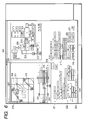
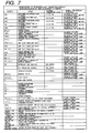
- Fig. 6 shows the detail of the exhaust system chart 122 and Fig. 7 is an overall chart which collectively indicates symbols of constituent parts of the exhaust system used in Fig. 6 and check points for operation and inspection.
- Fig. 6 is one screen of the display panel arranged in the inside of the display part and displays the layout (upper side) of the constituent elements of the wafer transport system (left side) and the exhaust system (right side) and the operation state of the main constituent elements (bottom side) using lamps.
- ST1 indicated by numeral 204 to ST3 indicated by numeral 205 are sensors which monitor the mounting state of the wafer when the wafer in the inside of a sample exchange chamber (XC) 206 is loaded or unloaded.
- the ST1 sensor monitors whether the wafer is accurately mounted on a station holder or not.
- W1 indicated by numeral 207 to W3 indicated by numeral 208 are sensors which monitor the mounting state of the wafer on the wafer holder.
- the W1 indicated by numeral 207 monitors whether the wafer is accurately mounted on the wafer holder, and the W2 indicated by numeral 223 monitors the presence of the wafer, and the W3 indicated by numeral 208 monitors whether the wafer is slanted or not.
- AV2Though 209 monitors whether a foreign material is present on AV2 indicated by numeral 210 when AV2 indicated by 210 is opened or after the wafer holder is loaded or unloaded in and the sample chamber.
- two wafer transport arms 211 are disposed, wherein an A arm is used when the wafer is transported from a center pallet 212 to the station holder 213.
- an air lock valve (AV2) 210 is opened and the wafers are transported to the SC on rails.
- the ST side wafer 215 and the W side wafer 216 in the drawing are loaded and unloaded using transport spaces by means of two arms A, B at the station holder side (ST) and the wafer holder side (W) capable of covering two sheets of wafers respectively.
- Chambers which constitute the wafer transport system are comprised of three chambers consisting of XC indicated by numeral 206, LC indicated by numeral 203 and SC indicated by numeral 214.
- a panel portion for monitoring the operation state of the LC which is positioned at the center out of these chambers is disposed at the left lower side of the drawing.
- An LED light position sensor detects the movement of a movable mechanism part and performs a lamp display.
- chambers, pumps, valves and piping are displayed in an illustrated manner, wherein the pumps and valves are displayed such that lamps are turned on during electricity is supplied and the valves are open, while during feeding of electricity is interrupted and the valves are closed, the lamps are turned off.
- the operation monitor panel of the exhaust system automatically performs the pump changeover operation using a vacuum gauge and hence, with respect to Penning gauges (Pe) 217 and Pirani gauges (Pi) 218, the operation monitor panel performs a panel display such that a lamp flickers at the changeover degree of vacuum being at a point 1 to 2.
- a turbo molecular pump (TMP) 219 erroneous operations (Fail) 220 are particularly displayed by lamps so as to enable an operator to take a prompt countermeasure. Lamps are also lit when an atmospheric pressure gauge (APS) 221 and a valve driving air pressure (APS) 222 are in a normal operation. Further, the pressure level in the inside of the vacuum chamber is displayed as black when the pressure is the atmospheric pressure and the display color is changed to red, yellow, blue and green corresponding to the decrease of pressure.
- the state of the XC is displayed by 231
- the state of the ARM (A arm, B arm) is displayed by 232
- the state of the AV2 is displayed by 233
- the state of the AV-3 is displayed by numeral 234.
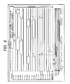
- Fig. 8 shows a timing chart which displays the basic monitor data and the monitoring history data with respect to respective constituent parts for monitoring the degree of vacuum in the example 1 and compares respective data in an overlaid manner.
- numeral 121 indicates the basic monitoring data
- numeral 122 indicates the monitoring history data. That is, the stored basic data and the stored monitoring data 79 which are shown in Fig. 3 are displayed on the screen using the function of the workstation 81.
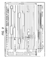
- Fig. 9 shows the difference in the vacuum recovery time of Pe-2 with respect to the example of Fig. 8.
- time necessary for recovering vacuum after the vacuum in the transport chamber 20 is temporarily deteriorated when the AV-3 valve is closed is shown.
- the vacuum pressure recovers at 3 ⁇ 10 -2 Pa after lapse of 0.4 seconds when the AV-3 is closed.
- the measured monitoring history data takes 1.2 seconds. It is instantaneously judged that there exists the time difference of 0.8 seconds, 13 times. Accordingly, it is recognized that some vacuum failure occurs on the device as an object with respect to the measured item.
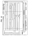
- Fig. 10 shows an example 2. That is, Fig. 10 shows an example in which the sample transport time monitoring is performed using the timing chart.
- Fig. 11 displays the difference in sample transport time with respect to the example shown in Fig. 10.
- This example is an example which compares the sample transport time in the transport sequence.
- the transport time for reference data is 12.4 seconds and the time for monitoring data is 13.6 seconds and hence, there exists a delay of 1.2 seconds between the monitoring data and the reference data.
- the difference of 10 % (1.2 seconds) usually does not constitute any serious problem, in this example, with respect to the operation time of the position sensor of the A arm (A arm Right/Left), compared to the operation time of the reference data which is 1.9 seconds, the operation time of the monitoring data is 3.1 seconds thus exhibiting the large difference (163 %).
- the process (the state of process) from the past recorded data which are collected and sampled to the occurrence of trouble in the device is displayed dynamically using drawings in an overlaid manner. Further, by incorporating (forming) the function of automatically producing the timing charts of respective driving systems and the timing chart of the vacuum valve OPEN/CLOSE into the device, it is possible to monitor the device state in real time.
- the basic monitoring data it is possible to adopt a portion of the preliminarily registered data or the stored operation history data.
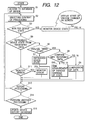
- Fig. 12 is an overall view of a flowchart for supporting the maintenance and the monitoring of trouble of the device in the computer system of the length-measuring SEM and Fig. 13 to Fig. 15 are partial views showing essential parts of Fig. 12 in detail.
- the support system gets access to the database in the device (S1), selects the processing content (S2), and judges whether the monitoring of the device state is to be performed or not (S3). When the judgement is affirmative, the monitoring of the state of the device is performed (S4).
- the device state monitoring data is preserved in real time.
- step S5 The processing is advanced from step S3 to step S5, wherein the device state from the registered data is reproduced and whether the analysis using the timing chart is to be performed or not is judged (S6) and the device state is reproduced (S7).
- the preserved device state monitoring data is reproduced. It is judged whether the comparison with the reference data is to be performed or not (S8).
- both data are compared (S9) or the measurement of time for change of various states is performed (S10).
- the comparison of both data is performed in accordance with the previously mentioned example 1 and example 2. In this case, however, the comparison and judgement of templates may be performed as shown in Fig. 16.
- Fig. 13 with respect to the partial data 300 sampled from the device in step S8, data to be compared may be cut and pasted to a preliminarily set plate so as to display the comparison and the result.
- step S5 the processing is advanced from step S5 to S11 and it is judged whether error monitoring is to be performed or not (S11) and then the error monitoring is performed.
- Step S13 it is judged whether the processing is to be repeated or not. Further, it is judged whether another processing is to be performed or not (S14). Then, updating of the history database of the device is performed (S15).
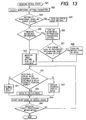
- Fig. 13 shows a flowchart for performing the monitoring of device state in step S4.
- the selection of monitoring setting parameters is performed (S22). Then, it is judged whether the monitoring is to be interrupted when an error occurs or not is judged (S23). Then, the error stop setting is turned on (S24). Further, it is judged whether the monitoring information is to be preserved or not (S25) and the monitoring information preserving setting is turned on (S26).
- Fig, 14 shows a detailed flow of the step S10.
- the data information is read from the registered data base (S42), it is judged whether the information is selected or not (S43), the necessary information is to be selected (S44), and the timing chart is produced based on the selected information (S45). Further, the timing chart is produced based on the total information (S46), and the targeted device state change time is measured using cursor arrow keys (S47), and it is judged whether other device state change time is to be measured or not (S48), and the processing returns.
- Fig. 15 shows a detailed flow of the step S11.
- the data information is read from the registered data base (S52), it is judged whether the information is selected or not (S53), the necessary information is selected (S54), and the timing chart is produced based on the selected information (S55). Further, the timing chart is produced based on the total information (S56), and data to be compared are selected (S57), and two data are compared using an overlay arrow key (S58). Time change quantity is measured using cursor arrow keys by comparing two data (S59), and it is judged whether other device state change is to be compared or not (S60), and the processing returns.
- a system and a method for supporting monitoring and diagnosing of maintenance and troubles related to the measuring device to which accelerated electron beams are applied in vacuum data from the operation monitoring sensors during the starting step and the measuring step of the measuring device are recorded and preserved in real time and synchronously. Then, timing and operation level are compared and reproduced by overlapping the data with data at the time of initial or normal operation. Further, when the difference which indicates that the maintenance is necessary or it is diagnosed that the trouble occurs is detected on data, probable trouble cause items are selected from pre-stored selection items on troubles and countermeasures against the troubles. Then, the result obtained by executing the preliminarily prepared confirmed matters for specifying the trouble causes are inputted so as to further specify the causes whereby the system and the method can support the maintenance and diagnosis of the device, and can preserve and make use of the diagnosis data.
- a system and method which adopts a system for supporting monitoring and diagnosing of maintenance and troubles by providing the position sensors and vacuum sensors to the electron lens/wafer driving parts and supply/exhaust parts of the length-measuring SEM.
- a system and method for monitoring maintenance and troubles related to measuring device which uses accelerated electron beams in vacuum.
- the accelerated electron beams which constitute measuring means must be generated in vacuum, to perform the maintenance and the diagnosis thereof, it is necessary to open the device so as to allow atmosphere to enter into the inside of the device conventionally. This makes the maintenance and the diagnosis difficult.
- the vacuum exhaust system and the sample driving system in the inside of the device By detecting a plurality of positions and movements related to the functions and performances of the electro-optic system, the vacuum exhaust system and the sample driving system in the inside of the device, the degree of vacuum and gas components, time and speed, image information and the like, the comparison between the detected data and the data in the initial state or the normal state can be performed on line simultaneously and in real time, whereby the device can instantly cope with the maintenance, the search of cause of trouble and countermeasures in an optimum manner.
Landscapes
- Physics & Mathematics (AREA)
- Engineering & Computer Science (AREA)
- Artificial Intelligence (AREA)
- Evolutionary Computation (AREA)
- Mathematical Physics (AREA)
- General Physics & Mathematics (AREA)
- Automation & Control Theory (AREA)
- Testing And Monitoring For Control Systems (AREA)
- Exposure Of Semiconductors, Excluding Electron Or Ion Beam Exposure (AREA)
- Length-Measuring Devices Using Wave Or Particle Radiation (AREA)
Abstract
Description
Claims (9)
- A monitoring device of a vacuum device having a vacuum system comprising:a screen display device;a screen display processing device which receives operation information signals from the vacuum system as input data and performs screen display processing so as to make the screen display device perform a screen display; anda memory device which stores basic monitoring data and operation history data of a plurality of constituent parts which constitute the vacuum system; whereinon a screen of the screen display device, the basic monitoring data and the operation history data of the plurality of constituent parts are displayed as timing charts which progress simultaneously in comparison, anda display which designates simultaneous time positions extending over a plurality of constituent parts of the vacuum system on the timing charts is performed.
- A monitoring device of a vacuum device having a vacuum system comprising:a screen display device;a screen display processing device which receives operation information signals from the vacuum system as input data and performs screen display processing so as to make the screen display device perform a screen display; anda memory device which stores basic monitoring data and operation history data of a plurality of constituent parts which constitute the vacuum system; whereinon a screen of the screen display device, the plurality of constituent parts are displayed, and the basic monitoring data and the operation history data of the constituent parts are displayed as timing charts which progress simultaneously in comparison, andwhen simultaneous time positions are designated extending over the plurality of constituent parts of the vacuum system on the timing charts, operation states of the constituent parts which correspond to the positions are displayed together.
- A monitoring device of a vacuum device having a vacuum system comprising:a screen display device;a screen display processing device which receives operation information signals from the vacuum system as input data and performs screen display processing so as to make the screen display device perform a screen display;a memory device which stores basic monitoring data and operation history data of a plurality of constituent parts which constitute the vacuum system and a predetermined difference between the basic monitoring data and the operation history data; anda processing device which compares the basic monitoring data and the operation history data of the plurality of constituent parts as timing charts which progress simultaneously, and judges whether any one of the plurality of constituent parts exceeds the difference at the designated simultaneous time.
- A monitoring device of a vacuum device having a vacuum system which produces a vacuum comprising:a screen display device;a screen display processing device which receives operation information signals from the vacuum system as input data and performs screen display processing so as to make the screen display device perform a screen display; anda memory device which stores basic monitoring data and operation history data of a plurality of constituent parts which constitute the vacuum system and a predetermined difference between the basic monitoring data and the operation history data; anda processing device which compares the basic monitoring data and the operation history data of the constituent parts as timing charts which progress simultaneously, and judges whether any one of the plurality of constituent parts exceeds the difference at the designated simultaneous time, whereinon a screen of the screen display device, the plurality of constituent parts are displayed, and the basic monitoring data and the operation history data of the constituent parts are displayed as timing charts which progress simultaneously in comparison, andwhen simultaneous time positions are designated extending over the plurality of constituent parts of the vacuum system on the timing charts, operation states of the constituent parts which correspond to the positions are displayed together.
- A monitoring device of a vacuum device according to any one of preceding claims 1 to 4, wherein the basic monitoring data is either pre-registered data or stored operation history data.
- A monitoring method of a vacuum device having a vacuum system which produces a vacuum comprising:a step in which operation information signals from the vacuum system are inputted as data and screen display processing is performed;a step in which basic monitoring data and operation history data of a plurality of constituent parts which constitute the vacuum system are stored;a step in which the basic monitoring data and the operation history data of the plurality of constituent parts are displayed on a screen in the screen display processing as timing charts which progress simultaneously in comparison; anda step of displaying on the screen which designates simultaneous time positions extending over the plurality of constituent parts of the vacuum system on the timing chart.
- A monitoring method of a vacuum device according to claim 6, wherein the method further includes a step in which the difference between the basic monitoring data and the operation history data is preliminarily determined and stored, and a step in which whether the constituent parts are within or outside the difference based on the timing charts is judged.
- A monitoring method of a vacuum device which has a vacuum system producing a vacuum and is installed at a remote place being characterized in that:operation information signals from the vacuum system of the vacuum device which is preliminarily determined by a contract are inputted as data and screen display processing is performed;basic monitoring data and operation history data of a plurality of constituent parts which constitute the vacuum system are stored;with respect to the vacuum device, the constituent parts are sequentially displayed on a screen of the screen display device, and the basic monitoring data and the operation history data of the plurality of constituent parts are displayed as timing charts which progress simultaneously in comparison; and when simultaneous time positions are designated extending over the plurality of constituent parts of the vacuum system on the timing charts, operation states of the constituent parts which correspond to the positions are reported.
- A monitoring method of a vacuum device which has a vacuum system producing a vacuum being characterized in that:operation information signals from the vacuum system of the vacuum device which is preliminarily determined by a contract are inputted as data through a communication network and screen display processing is performed;basic monitoring data and operation history data of a plurality of constituent parts which constitute the vacuum system are stored;with respect to the vacuum device, the constituent parts are sequentially displayed on a screen of the screen display device, and the basic monitoring data and the operation history data of the plurality of constituent parts are displayed as timing charts which progress simultaneously in comparison; andwhen simultaneous time positions are designated extending over the plurality of constituent parts of the vacuum system on the timing charts, operation states of the constituent parts which correspond to the positions are displayed; anda period necessary for the difference between the basic monitoring data and the operation history data to reach a predetermined difference is predicted based on the state of the difference between the basic monitoring data and the operation history data from the timing charts which progress simultaneously for every contract and next maintenance time is reported.
Applications Claiming Priority (2)
| Application Number | Priority Date | Filing Date | Title |
|---|---|---|---|
| JP2001303484A JP3793707B2 (en) | 2001-09-28 | 2001-09-28 | Monitoring device and monitoring method for vacuum apparatus |
| JP2001303484 | 2001-09-28 |
Publications (3)
| Publication Number | Publication Date |
|---|---|
| EP1298513A2 true EP1298513A2 (en) | 2003-04-02 |
| EP1298513A3 EP1298513A3 (en) | 2003-07-30 |
| EP1298513B1 EP1298513B1 (en) | 2006-06-14 |
Family
ID=19123562
Family Applications (1)
| Application Number | Title | Priority Date | Filing Date |
|---|---|---|---|
| EP02021694A Expired - Lifetime EP1298513B1 (en) | 2001-09-28 | 2002-09-27 | Monitoring device and monitoring method for vacuum device |
Country Status (5)
| Country | Link |
|---|---|
| US (2) | US6925423B2 (en) |
| EP (1) | EP1298513B1 (en) |
| JP (1) | JP3793707B2 (en) |
| KR (1) | KR20030027800A (en) |
| DE (1) | DE60212286T2 (en) |
Cited By (4)
| Publication number | Priority date | Publication date | Assignee | Title |
|---|---|---|---|---|
| EP1628179A1 (en) * | 2004-07-24 | 2006-02-22 | Cognis IP Management GmbH | Method and device for monitoring of product installations |
| WO2014088760A1 (en) * | 2012-12-07 | 2014-06-12 | General Electric Company | Methods and systems for integrated plot training |
| CN105980944A (en) * | 2014-02-11 | 2016-09-28 | 山特维克知识产权股份有限公司 | Slewing device monitoring apparatus and method |
| US9761027B2 (en) | 2012-12-07 | 2017-09-12 | General Electric Company | Methods and systems for integrated plot training |
Families Citing this family (22)
| Publication number | Priority date | Publication date | Assignee | Title |
|---|---|---|---|---|
| KR100790744B1 (en) * | 2003-09-23 | 2007-12-31 | 동부일렉트로닉스 주식회사 | Wafer Inspection Device |
| US7676342B2 (en) | 2004-12-23 | 2010-03-09 | Asml Netherlands B.V. | Sensor assembly, digital serial bus and protocol, sensor network, and lithographic apparatus and system |
| US9104650B2 (en) | 2005-07-11 | 2015-08-11 | Brooks Automation, Inc. | Intelligent condition monitoring and fault diagnostic system for preventative maintenance |
| JP5043839B2 (en) * | 2005-07-11 | 2012-10-10 | ブルックス オートメーション インコーポレイテッド | Intelligent condition monitoring and fault diagnosis system for predictive maintenance |
| US7289863B2 (en) | 2005-08-18 | 2007-10-30 | Brooks Automation, Inc. | System and method for electronic diagnostics of a process vacuum environment |
| JP5100191B2 (en) * | 2007-04-13 | 2012-12-19 | キヤノン株式会社 | Information processing apparatus and information processing method |
| JP4901784B2 (en) | 2008-03-05 | 2012-03-21 | 株式会社日立ハイテクノロジーズ | Charged particle beam equipment |
| JP2009303462A (en) * | 2008-06-17 | 2009-12-24 | Mitsubishi Electric Corp | Supervisory control system |
| US9141507B2 (en) * | 2009-12-23 | 2015-09-22 | Microsoft Technology Licensing, Llc | Visualization of states of a process |
| JP5303517B2 (en) | 2010-07-15 | 2013-10-02 | 株式会社日立ハイテクノロジーズ | Charged particle beam apparatus, defect observation apparatus, and management server |
| JP5748456B2 (en) * | 2010-11-19 | 2015-07-15 | シスメックス株式会社 | Sample transport system, sample processing system and control device |
| JP5548649B2 (en) * | 2011-05-31 | 2014-07-16 | 京セラドキュメントソリューションズ株式会社 | Image forming apparatus |
| US9606054B2 (en) * | 2013-09-30 | 2017-03-28 | Advantest Corporation | Methods, sampling device and apparatus for terahertz imaging and spectroscopy of coated beads, particles and/or microparticles |
| US9417181B2 (en) | 2014-05-08 | 2016-08-16 | Advantest Corporation | Dynamic measurement of density using terahertz radiation with real-time thickness measurement for process control |
| WO2017179137A1 (en) * | 2016-04-13 | 2017-10-19 | 株式会社 日立ハイテクノロジーズ | Charged particle beam device |
| US11232014B2 (en) | 2018-04-30 | 2022-01-25 | Hewlett-Packard Development Company, L.P. | Countermeasure implementation for processing stage devices |
| JP6851348B2 (en) * | 2018-08-15 | 2021-03-31 | 日本電子株式会社 | Vacuum equipment and recovery support method |
| CN114424316B (en) * | 2019-08-28 | 2024-12-10 | Asml荷兰有限公司 | Self-referencing health monitoring system for multi-beam SEM tools |
| GB2594309A (en) * | 2020-04-23 | 2021-10-27 | Edwards Ltd | Monitoring and controlling the monitoring of vacuum systems |
| JP7588980B2 (en) * | 2020-07-31 | 2024-11-25 | キヤノン株式会社 | Information processing device, control method for information processing device, production system, product manufacturing method, control program, and recording medium |
| EP3995080A1 (en) * | 2020-11-09 | 2022-05-11 | Koninklijke Philips N.V. | Maintenance prediction for a medical imaging apparatus |
| US20230280736A1 (en) * | 2022-03-02 | 2023-09-07 | Applied Materials, Inc. | Comprehensive analysis module for determining processing equipment performance |
Family Cites Families (23)
| Publication number | Priority date | Publication date | Assignee | Title |
|---|---|---|---|---|
| JPS58113713A (en) | 1981-12-26 | 1983-07-06 | Toshiba Corp | Data recorder |
| JPS58113830A (en) | 1981-12-28 | 1983-07-06 | Anelva Corp | Vacuum measuring device |
| JPH01276205A (en) * | 1988-04-27 | 1989-11-06 | Mazda Motor Corp | Monitoring device for sequence program control system |
| JPH02157909A (en) * | 1988-12-09 | 1990-06-18 | Toshiba Corp | Plant operation manipulating device |
| JP2947840B2 (en) * | 1989-12-22 | 1999-09-13 | 株式会社日立製作所 | Plant operation monitoring device |
| JPH04190133A (en) * | 1990-11-24 | 1992-07-08 | Hitachi Ltd | Diagnosis support apparatus of equipment |
| JP3126493B2 (en) * | 1991-06-25 | 2001-01-22 | 松下電工株式会社 | Equipment failure diagnosis method |
| US5452417A (en) * | 1993-11-23 | 1995-09-19 | Honeywell Inc. | Real time display system for showing the status of an operating system |
| JP3085095B2 (en) * | 1994-07-25 | 2000-09-04 | 株式会社日立製作所 | Plant monitoring device and monitoring method |
| JP3274581B2 (en) * | 1995-02-22 | 2002-04-15 | 株式会社日立製作所 | Process monitoring device |
| JPH09306409A (en) * | 1996-05-20 | 1997-11-28 | Hitachi Ltd | Scanning electron microscope |
| JP3554128B2 (en) * | 1997-01-21 | 2004-08-18 | 株式会社日立製作所 | Recording information display system and recording information display method |
| JPH10239487A (en) * | 1997-02-24 | 1998-09-11 | Hitachi Ltd | Plant operation support device |
| JPH10321177A (en) * | 1997-05-15 | 1998-12-04 | Shimadzu Corp | Device status display method for electron beam device |
| US6076026A (en) * | 1997-09-30 | 2000-06-13 | Motorola, Inc. | Method and device for vehicle control events data recording and securing |
| JPH11118528A (en) * | 1997-10-09 | 1999-04-30 | Kokusai Electric Co Ltd | Measurement data display device |
| US6123983A (en) * | 1998-04-23 | 2000-09-26 | Sandia Corporation | Method and apparatus for monitoring plasma processing operations |
| SG74705A1 (en) * | 1999-03-12 | 2001-06-19 | Sony Electronics Singapore Pte | A monitoring system for monitoring processing equipment |
| JP4056032B2 (en) * | 1999-10-27 | 2008-03-05 | 株式会社東芝 | Plant equipment management device |
| EP1273718B1 (en) * | 2000-03-31 | 2012-08-01 | Hitachi Construction Machinery Co., Ltd. | Method and system for managing construction machine |
| US6618692B2 (en) * | 2000-09-20 | 2003-09-09 | Hitachi, Ltd. | Remote diagnostic system and method for semiconductor manufacturing equipment |
| US6683316B2 (en) * | 2001-08-01 | 2004-01-27 | Aspex, Llc | Apparatus for correlating an optical image and a SEM image and method of use thereof |
| US6687654B2 (en) * | 2001-09-10 | 2004-02-03 | The Johns Hopkins University | Techniques for distributed machinery monitoring |
-
2001
- 2001-09-28 JP JP2001303484A patent/JP3793707B2/en not_active Expired - Lifetime
-
2002
- 2002-09-25 US US10/253,485 patent/US6925423B2/en not_active Expired - Lifetime
- 2002-09-27 KR KR1020020058753A patent/KR20030027800A/en not_active Ceased
- 2002-09-27 DE DE60212286T patent/DE60212286T2/en not_active Expired - Lifetime
- 2002-09-27 EP EP02021694A patent/EP1298513B1/en not_active Expired - Lifetime
-
2005
- 2005-06-24 US US11/165,577 patent/US7117127B2/en not_active Expired - Lifetime
Cited By (5)
| Publication number | Priority date | Publication date | Assignee | Title |
|---|---|---|---|---|
| EP1628179A1 (en) * | 2004-07-24 | 2006-02-22 | Cognis IP Management GmbH | Method and device for monitoring of product installations |
| WO2014088760A1 (en) * | 2012-12-07 | 2014-06-12 | General Electric Company | Methods and systems for integrated plot training |
| US9761027B2 (en) | 2012-12-07 | 2017-09-12 | General Electric Company | Methods and systems for integrated plot training |
| CN105980944A (en) * | 2014-02-11 | 2016-09-28 | 山特维克知识产权股份有限公司 | Slewing device monitoring apparatus and method |
| CN105980944B (en) * | 2014-02-11 | 2018-09-25 | 艾法史密斯有限公司 | The monitoring device and method of slewing equipment |
Also Published As
| Publication number | Publication date |
|---|---|
| EP1298513A3 (en) | 2003-07-30 |
| KR20030027800A (en) | 2003-04-07 |
| DE60212286D1 (en) | 2006-07-27 |
| DE60212286T2 (en) | 2007-04-26 |
| EP1298513B1 (en) | 2006-06-14 |
| US20060004544A1 (en) | 2006-01-05 |
| US7117127B2 (en) | 2006-10-03 |
| JP3793707B2 (en) | 2006-07-05 |
| JP2003108223A (en) | 2003-04-11 |
| US20030063123A1 (en) | 2003-04-03 |
| US6925423B2 (en) | 2005-08-02 |
Similar Documents
| Publication | Publication Date | Title |
|---|---|---|
| EP1298513B1 (en) | Monitoring device and monitoring method for vacuum device | |
| JP4564728B2 (en) | Circuit pattern inspection device | |
| JP5303517B2 (en) | Charged particle beam apparatus, defect observation apparatus, and management server | |
| EP1300874B1 (en) | Method for maintaining a processor | |
| US8184283B2 (en) | Optical defect inspection apparatus | |
| JP4922962B2 (en) | Circuit pattern inspection method and inspection apparatus | |
| JP2004071671A (en) | Foreign substance monitoring system, process processing apparatus, and electronic commerce method | |
| JP4985090B2 (en) | X-ray fluorescence analyzer, X-ray fluorescence analysis method and program | |
| US7075074B2 (en) | Electron beam inspection apparatus and method for testing an operation state of an electron beam inspection apparatus | |
| JP3858935B2 (en) | Monitoring method and monitoring system | |
| JP3992066B2 (en) | Monitoring device and monitoring method for vacuum apparatus | |
| JPH06347246A (en) | Scanning electron microscope with length measurement function | |
| US7478014B2 (en) | Method and system for facilitating preventive maintenance of an optical inspection tool | |
| US7831083B1 (en) | Image quality monitoring for substrate inspection | |
| JPH0915056A (en) | Temperature monitoring device | |
| JP4218074B2 (en) | Electron beam defect inspection apparatus and defect inspection method | |
| US7446313B2 (en) | Scanning electron microscope | |
| TWI845656B (en) | System and method of inspecting and reviewing semiconductor wafers, and non-transitory computer-readable storage medium | |
| JP4035299B2 (en) | Electron microscope electron gun monitoring apparatus and method | |
| JP2007242287A (en) | X-ray output device diagnosis apparatus and X-ray output device diagnosis method | |
| JP2003100248A (en) | Pattern inspection system using charged particle beam | |
| JPH06255925A (en) | Inspection operation device of elevator | |
| JPH0237346A (en) | Device and method for correcting pattern | |
| KR20040023889A (en) | Quality monitoring apparatus and method for substrate with film |
Legal Events
| Date | Code | Title | Description |
|---|---|---|---|
| PUAI | Public reference made under article 153(3) epc to a published international application that has entered the european phase |
Free format text: ORIGINAL CODE: 0009012 |
|
| AK | Designated contracting states |
Kind code of ref document: A2 Designated state(s): AT BE BG CH CY CZ DE DK EE ES FI FR GB GR IE IT LI LU MC NL PT SE SK TR |
|
| AX | Request for extension of the european patent |
Extension state: AL LT LV MK RO SI |
|
| PUAL | Search report despatched |
Free format text: ORIGINAL CODE: 0009013 |
|
| AK | Designated contracting states |
Designated state(s): AT BE BG CH CY CZ DE DK EE ES FI FR GB GR IE IT LI LU MC NL PT SE SK TR |
|
| AX | Request for extension of the european patent |
Extension state: AL LT LV MK RO SI |
|
| 17P | Request for examination filed |
Effective date: 20030930 |
|
| AKX | Designation fees paid |
Designated state(s): DE FR |
|
| 17Q | First examination report despatched |
Effective date: 20040625 |
|
| GRAP | Despatch of communication of intention to grant a patent |
Free format text: ORIGINAL CODE: EPIDOSNIGR1 |
|
| GRAS | Grant fee paid |
Free format text: ORIGINAL CODE: EPIDOSNIGR3 |
|
| GRAA | (expected) grant |
Free format text: ORIGINAL CODE: 0009210 |
|
| RAP1 | Party data changed (applicant data changed or rights of an application transferred) |
Owner name: HITACHI, LTD. |
|
| AK | Designated contracting states |
Kind code of ref document: B1 Designated state(s): DE FR |
|
| REF | Corresponds to: |
Ref document number: 60212286 Country of ref document: DE Date of ref document: 20060727 Kind code of ref document: P |
|
| ET | Fr: translation filed | ||
| PLBE | No opposition filed within time limit |
Free format text: ORIGINAL CODE: 0009261 |
|
| STAA | Information on the status of an ep patent application or granted ep patent |
Free format text: STATUS: NO OPPOSITION FILED WITHIN TIME LIMIT |
|
| 26N | No opposition filed |
Effective date: 20070315 |
|
| PGFP | Annual fee paid to national office [announced via postgrant information from national office to epo] |
Ref country code: FR Payment date: 20080814 Year of fee payment: 7 |
|
| REG | Reference to a national code |
Ref country code: FR Ref legal event code: ST Effective date: 20100531 |
|
| PG25 | Lapsed in a contracting state [announced via postgrant information from national office to epo] |
Ref country code: FR Free format text: LAPSE BECAUSE OF NON-PAYMENT OF DUE FEES Effective date: 20090930 |
|
| PGFP | Annual fee paid to national office [announced via postgrant information from national office to epo] |
Ref country code: DE Payment date: 20140923 Year of fee payment: 13 |
|
| REG | Reference to a national code |
Ref country code: DE Ref legal event code: R119 Ref document number: 60212286 Country of ref document: DE |
|
| PG25 | Lapsed in a contracting state [announced via postgrant information from national office to epo] |
Ref country code: DE Free format text: LAPSE BECAUSE OF NON-PAYMENT OF DUE FEES Effective date: 20160401 |