EP1298409A1 - A system for launching a war head with a trajectory correction device for neutralisation of mines - Google Patents
A system for launching a war head with a trajectory correction device for neutralisation of mines Download PDFInfo
- Publication number
- EP1298409A1 EP1298409A1 EP02017902A EP02017902A EP1298409A1 EP 1298409 A1 EP1298409 A1 EP 1298409A1 EP 02017902 A EP02017902 A EP 02017902A EP 02017902 A EP02017902 A EP 02017902A EP 1298409 A1 EP1298409 A1 EP 1298409A1
- Authority
- EP
- European Patent Office
- Prior art keywords
- laser
- warhead
- throwing system
- mine
- mines
- Prior art date
- Legal status (The legal status is an assumption and is not a legal conclusion. Google has not performed a legal analysis and makes no representation as to the accuracy of the status listed.)
- Granted
Links
Images


Classifications
-
- F—MECHANICAL ENGINEERING; LIGHTING; HEATING; WEAPONS; BLASTING
- F41—WEAPONS
- F41H—ARMOUR; ARMOURED TURRETS; ARMOURED OR ARMED VEHICLES; MEANS OF ATTACK OR DEFENCE, e.g. CAMOUFLAGE, IN GENERAL
- F41H11/00—Defence installations; Defence devices
- F41H11/12—Means for clearing land minefields; Systems specially adapted for detection of landmines
-
- F—MECHANICAL ENGINEERING; LIGHTING; HEATING; WEAPONS; BLASTING
- F41—WEAPONS
- F41B—WEAPONS FOR PROJECTING MISSILES WITHOUT USE OF EXPLOSIVE OR COMBUSTIBLE PROPELLANT CHARGE; WEAPONS NOT OTHERWISE PROVIDED FOR
- F41B7/00—Spring guns
-
- F—MECHANICAL ENGINEERING; LIGHTING; HEATING; WEAPONS; BLASTING
- F41—WEAPONS
- F41G—WEAPON SIGHTS; AIMING
- F41G3/00—Aiming or laying means
- F41G3/12—Aiming or laying means with means for compensating for muzzle velocity or powder temperature with means for compensating for gun vibrations
-
- F—MECHANICAL ENGINEERING; LIGHTING; HEATING; WEAPONS; BLASTING
- F41—WEAPONS
- F41G—WEAPON SIGHTS; AIMING
- F41G7/00—Direction control systems for self-propelled missiles
- F41G7/20—Direction control systems for self-propelled missiles based on continuous observation of target position
- F41G7/30—Command link guidance systems
- F41G7/301—Details
-
- F—MECHANICAL ENGINEERING; LIGHTING; HEATING; WEAPONS; BLASTING
- F42—AMMUNITION; BLASTING
- F42B—EXPLOSIVE CHARGES, e.g. FOR BLASTING, FIREWORKS, AMMUNITION
- F42B10/00—Means for influencing, e.g. improving, the aerodynamic properties of projectiles or missiles; Arrangements on projectiles or missiles for stabilising, steering, range-reducing, range-increasing or fall-retarding
- F42B10/60—Steering arrangements
- F42B10/66—Steering by varying intensity or direction of thrust
- F42B10/661—Steering by varying intensity or direction of thrust using several transversally acting rocket motors, each motor containing an individual propellant charge, e.g. solid charge
Definitions
- the invention relates to a system for moving a warhead in a target area as specified in the preamble of claim 1 Features.
- Methods to make the mine so safe to use that it is absorbed and can be blown up in a safe place is to apply it a quick-curing foam to secure the igniter or through Liquid helium cooling to block the trigger mechanism.
- On-board weapons such as machine guns used. These destroy the Mine mechanically or trigger it via the ignition device.
- a mine can be neutralized from a safe distance with fire Damage to the mine will cause an approximation of one Mine clearer no longer allows.
- the fire at hidden mines is basically out of the question. Even if the mine position is visual is marked, the angle of fire from a vehicle is so unfavorable that in many cases the penetration length in the earth area is too long.
- the basic idea of the throwing system according to the invention is one Splinter warhead precisely above the visible mine or - if the mine is below the surface of the earth is not visibly laid - to ignite above its position is either optically marked and / or known as a coordinate.
- the trigger The fragmentation warhead causes every mine to be up to and 30 cm below the surface of the earth is destroyed by the action of fragments.
- the fragment charge contains a fragment density of approximately 0.2 fragments / cm 2 .
- the splinter warhead reaches this splinter density in a circular area of approximately one meter in diameter. To achieve the intended effect, the mine to be destroyed must be within this circle.
- the mortar principle lends itself to degrees.
- the allowable deviation from the target trajectory may - if, for example, a 38 cm mine completely should be hit - not more than 31 cm. This accuracy can cannot be achieved with a mortar with pyrotechnic drive.
- the mechanism of neutralization is based on mine action mechanically by splinters so that they are no longer a danger represent.
- the advantage of this method is that regardless of the Size, design, ignition mechanism and type of installation (on or under surface of the mine) has a high probability of neutralization (also against smart mines).
- the combination of a high-precision mechanical throwing system and one Trajectory correction device ensures that the splinter warhead comes into effect precisely above the mine position and thus a high one Splinter density can be achieved.
- the trajectory correction by microreaction engines is based on one proven technology that enables extremely simple realizations. With only three microreaction engines on the perimeter of the floor can be used once a trajectory correction can be achieved which is the crucial improvement in the accuracy.
- the timing for neutralization is minimal. After recognizing the The mine position is neutralized after approx. 10 seconds.
- the throwing system is excellent for a technical implementation as Suitable kit.
- the modules to be modified change the signature of the Vehicle only insignificantly.
- the throwing system according to the invention enables the implementation of a set-up kit that from the sub-areas of throwing system 20 with straightening device 21, Laser illuminator 7 and fragmentation warhead 3 exists.
- Figures 1 and 2 illustrate the throwing system 20 with the aiming device 21 for the precise movement of the fragmentation warhead 3.
- the straightening device 21 enables the throwing system 20 to be aligned in an azimuth direction 22 in one Range from approx. 0 to 180 degrees and in elevation direction 23 in one area from approx. 60 to 80 degrees.
- a transport position with 0 degrees is provided.
- Throwing system 20 are preferably designed as a feather throwing system significantly lower compared to pyrotechnic transport mechanisms Scattering of the target trajectory allows.
- the principle is to tension springs 1 by means of electric motors 2 so far that when the springs 1 are released the splinter warhead 3 is exactly one selectable starting speed.
- the force / path of the springs 1, which corresponds to this energy, can be used to regulate the clamping process by electric motors 2 precisely via force elements or current sensors 4 in the Power supply of the electric motors 2 are measured. With that, too Influences by temperature and material fatigue in the springs 2 largely be balanced. Since gas-tight guidance of the fragmentation warhead 3 omitted, the fragmentation warhead 3 z. B. in a cup 5 by the Springs 1 is accelerated via a play-free roller guide 6, with less Leaving scatter can be ejected.
- the laser illuminator 7 shown in FIG. 3 can have two laser beams 8, 9 can be positioned independently of one another in azimuth and elevation, wherein the laser illuminator 7 is positioned on a vehicle 19.
- the first laser beam 8 is used to illuminate a mine 10 or one Surface position under which the mine 10 is located.
- the laser beam 8 can by the vehicle crew via manual aiming at a target recognized mine 10 are performed or automatically via a not closer control unit shown are directed. For this automatic control are then the exact position of the mine and the exact position and direction of the vehicle 19 required.
- the second laser beam 9 has the shape of a fan. Elevation and Azimuth angles are determined with reference to the spatial position of the Illumination laser beam 8 automatically determined.
- the azimuth angle of the The center line of the fan corresponds to the azimuth angle of the illumination laser 8, the elevation angle is larger than the elevation angle by such a value of the illumination laser 8, so that the beam fan 9 in a preselectable Distance 28, which is, for example, 2-4 m above the lighting position 29 of mine 10 runs.
- This laser beam 9 is encoded.
- the fragmentation warhead 3 consists of the following Assemblies: One warhead body 11, one fragmentation charge 12, one on the end of the fragmentation warhead 3 arranged laser position detector 13, the position of the laser light spot 29 of the illumination laser 8 determined, a laser detector 14 with decoding device for detecting the coded laser fan 9, three microreaction engines 15 with ignition device, which are attached to the umfana of the warhead by 120 degrees. and a control and evaluation unit 16, which controls the Laser position detector 13, the laser detector 14, the microreaction engines 15, as well as the ignition of the warhead.
- the throwing system works as follows:
- the electronics and ignition device of the warhead 3 is by the Throwing process activated. Approximately The warhead 3 dives 3 m above the ground 24 through the laser fan 9. This event is detected by the laser detector 14 Decoding device detected. This turns the laser position detector 13 on the front of the warhead 3 turned on, the direction of Impact point 25 to the illumination point 29 of the mine 10. The Direction is determined only as a sector. The number of sectors determines by the number of microreaction engines 15. With three on the circumference 17 equally distributed microreaction engines 15 can be ignited by one or two engines 15 displaced a total of six by 60 degrees each Deflections 18 can be achieved. This is a resolution of the search area in Six directional segments of 60 degrees each are required, depending on the Segment one or two microreaction engines 15 are ignited.
- the laser position detector 13 determines whether the trajectory 27 ends in the spot 29 of the illumination laser 8 or the trajectory 27 has a deposit 26. If a shelf 26 is provided, the angle is measured and the associated one or two engines 15 are ignited. This causes a correction of the trajectory 27 in the direction of the illumination spot 10. Since the height of the laser fan 9 above the surface of the earth and the speed of the warhead are known, the fragmentation warhead 3 can be released about 1 m above the ground after a certain time in which the correction of the trajectory has been completed. The fragments, not shown, are thereby ejected downwards in an approximately uniform distribution at a speed of approx. 800 m / s.
- the release height, the ejection characteristics and the number of splinters are selected so that a splinter density of 0.2 splinters / cm 2 is achieved in a circle of approximately one meter in diameter.
- the kinetic energy of the splinters is sufficient to safely destroy the mines after penetrating 30 cm of soil.
Abstract
Description
Die Erfindung betrifft ein System für eine Verbringung eines Gefechtskopfes in
ein Zielgebiet nach dem im Oberbegriff des Patentanspruchs 1 angegebenen
Merkmalen.The invention relates to a system for moving a warhead in
a target area as specified in the preamble of
In mit militärischen Mitteln geführten Konflikten stellen Minen für alle Beteiligten eine besondere Bedrohung dar. Diese resultiert aus der Fehlzahl unterschiedlicher Wirkungs- und Ablösemechanismen, Bauausführungen und Verlegearten sowohl der smart mines oder auch als dump mines. Diese Eigenschaften sind auch die Ursache dafür, dass Manipulationen an verlegten Minen eine unakzeptable Gefährdung des Personals bedeuten. Bei den bekannten Verfahren zur Neutralisierung von Minen muss immer damit gerechnet werden, dass die Mine auslöst. Damit muss die Neutralisierung durch technische Maßnahmen so erfolgen, dass das Personal nicht gefährdet wird. Besonders problematisch ist die Neutralisierung von Minen unter der Erdoberfläche, deren Typ und Zustand in der Regel nicht bekannt sind.In conflicts led by military means, mines provide for everyone involved is a particular threat. This results from the shortage different effects and detachment mechanisms, construction types and Laying of both the smart mines or as dump mines. This Properties are also the reason why tampering with misplaced Mines pose an unacceptable risk to personnel. Both Known methods of neutralizing mines must always be used are expected to trigger the mine. So neutralization has to go through technical measures are taken so that the personnel are not endangered. The neutralization of mines under the mine is particularly problematic Earth's surface, the type and condition of which are generally not known.
Erkannte einzelne Minen werden bislang überwiegend pyrotechnisch geräumt. Liegt eine Mine offen, wird eine Hohlladung so neben der Mine positioniert, dass der Hohlladungsstrahl in den Sprengstoff wirkt. Eine einfachere Methode besteht im Auflegen einer Schlagladung, die die Mine durch Zündübertragung und / oder mechanisch zerstört. Beide Methoden haben den Nachteil, dass die Mine bei Auslösung erhebliche Schäden verursachen kann, insbesondere wenn sie in urbanem Gebiet liegt.Detected individual mines have so far been largely pyrotechnically cleared. If a mine is open, a shaped charge is positioned next to the mine in such a way that the shaped charge jet acts in the explosive. There is an easier method im laying a blow charge that the mine by ignition transmission and / or mechanically destroyed. Both methods have the disadvantage that the mine Tripping can cause significant damage, especially if it is in urban area.
Methoden, die Mine so handhabungssicher zu machen, dass sie aufgenommen und an einem sicheren Ort gesprengt werden kann, bestehen in dem Aufbringen eines schnellhärtenden Schaums zur Sicherstellung des Zünders oder durch Kühlung mit flüssigem Helium, um den Auslösemechanismus zu blockieren.Methods to make the mine so safe to use that it is absorbed and can be blown up in a safe place is to apply it a quick-curing foam to secure the igniter or through Liquid helium cooling to block the trigger mechanism.
Um Minen aus größerer Distanz zu neutralisieren, werden in der Regel Bordwaffen, beispielsweise Maschinengewehre eingesetzt. Diese zerstören die Mine mechanisch oder lösen sie über die Zündeinrichtung aus.In order to neutralize mines from a greater distance, usually On-board weapons, such as machine guns used. These destroy the Mine mechanically or trigger it via the ignition device.
Alle Maßnahmen zur Minenneutralisierung, die von einem Minenräumer in direkter Nähe zur Mine durchgeführt werden müssen, stellen ein inakzeptables Gefährdungspotenzial dar.All mine neutralization measures by a deminer in direct proximity to the mine must be carried out, making an unacceptable Hazard potential.
Hierzu kommt, dass die meisten Methoden mit ausreichender Zuverlässigkeit nur bei offenliegenden Minen anwendbar sind. Bei verdeckt liegenden Minen kann weder der Typ, der Zustand, noch die Einbaulage und genaue Position sicher bestimmt werden. Ansprengungen mit Schlag- oder Hohlladungen sind dann wirkungslos, wenn die vermutete Position der Mine nicht mit der wirklichen Lage übereinstimmt.On top of that comes most methods with sufficient reliability only are applicable to exposed mines. With hidden mines neither the type, the condition, nor the installation position and exact position is certain be determined. Blasting with blow or shaped charges are then ineffective if the assumed position of the mine is not with the real location matches.
Eine Neutralisierung einer Mine aus sicherer Distanz mit Beschuss kann zu Beschädigungen der Mine führen, die dann eine Annäherung eines Minenräumers gar nicht mehr zulässt. Der Beschuss verdeckt verlegter Minen kommt im Grunde nicht in Frage. Selbst, wenn die Minenposition optisch markiert ist, ist der Beschusswinkel von einem Fahrzeug derart ungünstig, dass in vielen Fällen die Penetrationslänge im Erdbereich zu groß ist.A mine can be neutralized from a safe distance with fire Damage to the mine will cause an approximation of one Mine clearer no longer allows. The fire at hidden mines is basically out of the question. Even if the mine position is visual is marked, the angle of fire from a vehicle is so unfavorable that in many cases the penetration length in the earth area is too long.
Demgegenüber ist es Aufgabe der Erfindung, ein System für eine Verbringung
eines Gefechtskopfes in ein Zielgebiet mit einer Richtvorrichtung bereitzustellen,
das folgende Anforderungen erfüllen soll:
Gelöst wird diese Aufgabe durch die im Patentanspruch 1 angegebenen
Merkmale.This object is achieved by the specified in
Vorteilhafte Weiterbildungen des Systems gehen aus den Merkmalen der Unteransprüche hervor.Advantageous further developments of the system result from the features of Subclaims.
Die Grundidee des erfindungsgemäßen Wurfsystems besteht darin, einen Splittergefechtskopf präzise über der sichtbaren Mine oder - falls die Mine unter der Erdoberfläche nicht sichtbar verlegt ist - über ihrer Position zu zünden, die entweder optisch markiert und / oder als Koordinate bekannt ist. Die Auslösung des Splittergefechtskopfes bewirkt, dass jede Mine auf und bis zu 30 cm unter der Erdoberfläche durch Einwirkung von Splittern zerstört wird. The basic idea of the throwing system according to the invention is one Splinter warhead precisely above the visible mine or - if the mine is below the surface of the earth is not visibly laid - to ignite above its position is either optically marked and / or known as a coordinate. The trigger The fragmentation warhead causes every mine to be up to and 30 cm below the surface of the earth is destroyed by the action of fragments.
Die Einwirkung der Splitter führt bei Minen mit mechanischen Zündern in der Regel zur Auslösung. Bei Minen mit elektrischen Zündern, Richtminen o. ä. findet eine Auslösung aufgrund des Zündprinzips nicht statt. Diese Minen werden aber so zerstört, dass eine spätere, unkontrollierte Zündung ausgeschlossen ist. Der Sprengstoff allein stellt keine unmittelbare Gefährdung dar.The action of the splinters leads to mines with mechanical detonators in the Rule for triggering. For mines with electrical detonators, directional mines or similar there is no triggering due to the ignition principle. These mines will be but destroyed so that a later, uncontrolled ignition is impossible. The explosives alone are not an immediate hazard.
Um dieses im Grundsatz einfache Wirkprinzip zu realisieren, müssen bei dem Splittergefechtskopf technisch mehrere Voraussetzungen erfüllt sein:
- Die Splitterdichte muss so hoch sein, dass der Zünder mit Sicherheit getroffen und zerstört wird.
- Die Durchschlagsleistung der Splitter muss so hoch sein, dass auch nach Durchdringen von 25 - 30 cm Erdboden noch ausreichende kinetische Energie zur Zerstörung der Zünderbaugruppe vorhanden ist.
- The fragment density must be so high that the detonator will be hit and destroyed with certainty.
- The breakdown performance of the splinters must be high enough that even after penetrating 25 - 30 cm of soil there is sufficient kinetic energy to destroy the igniter assembly.
Um diese Leistungen zu erfüllen, enthält die Splitterladung eine Splitterdichte von ca. 0,2 Splitter / cm2. Bei der für die Penetration notwendigen Splittermasse erreicht der Splittergefechtskopf diese Splitterdichte in einer kreisförmigen Fläche von ca. einem Meter Durchmesser. Um die beabsichtigte Wirkung zu erzielen, muss sich die zu zerstörende Mine also innerhalb dieses Kreises befinden.In order to meet these requirements, the fragment charge contains a fragment density of approximately 0.2 fragments / cm 2 . With the splinter mass required for penetration, the splinter warhead reaches this splinter density in a circular area of approximately one meter in diameter. To achieve the intended effect, the mine to be destroyed must be within this circle.
Um einen Wirkkörper über eine Distanz von ca. 20 bis 70 m so zu verbringen, dass er auf einen vorbestimmten Punkt am Boden in einem Winkel von > 70 Grad auftrifft, bietet sich das Mörserprinzip an. Die zulässige Abweichung von der Sollflugbahn darf - wenn beispielsweise eine 38 cm Mine vollständig getroffen werden soll - nicht mehr als 31 cm betragen. Diese Genauigkeit kann mit einem Mörser mit pyrotechnischem Antrieb nicht erreicht werden.In order to spend an active body over a distance of approx. 20 to 70 m, that it is at a predetermined point on the ground at an angle of> 70 The mortar principle lends itself to degrees. The allowable deviation from the target trajectory may - if, for example, a 38 cm mine completely should be hit - not more than 31 cm. This accuracy can cannot be achieved with a mortar with pyrotechnic drive.
Um die notwendige Genauigkeit zu erzielen, sind zwei Maßnahmen vorgesehen:
- Statt eines pyrotechnischen Mörsers zur Verbringung des Splittergefechtskopfes wird ein Wurfsystem mit kontrollierter Federspannungsenergie eingesetzt, das mit vergleichbaren geometrischen Abmessungen eine gegenüber einem Mörser höhere Qualität der Reproduzierbarkeit der Abgangsgeschwindigkeit, geringere Abgangsfehler durch präzise Rollenlagerführung während der Beschleunigungsphase und weitgehende Temperaturunabhängigkeit durch Messung der Energie der Feder während des elektromotorischen Spannvorganges aufweist.
- Der Gefechtskopf wird mit zwei Mikroreaktionstriebwerken so bestückt, dass einige Meter vor Erreichen des Detonationspunktes die Flugbahn korrigiert werden kann. Diese Korrektur wird durch einen Sensor gesteuert, der die Flugbahnabweichung erfasst.
- Instead of a pyrotechnic mortar for moving the fragmentation warhead, a throwing system with controlled spring tension energy is used, which, with comparable geometric dimensions, has a higher reproducibility of the exit speed compared to a mortar, lower exit errors due to precise roller bearing guidance during the acceleration phase and extensive temperature independence by measuring the energy of the spring during of the electromotive clamping process.
- The warhead is equipped with two microreaction engines so that the trajectory can be corrected a few meters before the detonation point is reached. This correction is controlled by a sensor that detects the flight path deviation.
Der Mechanismus der Neutralisierung beruht darauf, Minen durch Einwirkung von Splittern mechanisch so zu zerstören, dass sie keine Gefahr mehr darstellen. Der Vorteil dieses Verfahrens besteht darin, dass unabhängig von der Größe, der Bauform, des Zündmechanismus und der Verlegeart (auf oder unter der Erdoberfläche) der Mine eine hohe Neutralisierungswahrscheinlichkeit (auch gegen smart mines) gegeben ist.The mechanism of neutralization is based on mine action mechanically by splinters so that they are no longer a danger represent. The advantage of this method is that regardless of the Size, design, ignition mechanism and type of installation (on or under surface of the mine) has a high probability of neutralization (also against smart mines).
Die Kombination eines hochpräzisen mechanischen Wurfsystems und einer Vorrichtung zur Flugbahnkorrektur stellt sicher, dass der Splittergefechtskopf präzise über der Minenposition zur Wirkung kommt und damit eine hohe Splitterdichte erzielt werden kann.The combination of a high-precision mechanical throwing system and one Trajectory correction device ensures that the splinter warhead comes into effect precisely above the mine position and thus a high one Splinter density can be achieved.
Die Flugbahnkorrektur durch Mikroreaktionstriebwerke basiert auf einer erprobten Technik, die ausgesprochen einfache Realisierungen ermöglicht. Mit nur drei Mikroreaktionstriebwerken am Umfang des Geschosses kann einmalig eine Flugbahnkorrektur erzielt werden, die die entscheidende Verbesserung in der Treffgenauigkeit bewirkt.The trajectory correction by microreaction engines is based on one proven technology that enables extremely simple realizations. With only three microreaction engines on the perimeter of the floor can be used once a trajectory correction can be achieved which is the crucial improvement in the accuracy.
Der Einsatz eines Lasers zur Übermittlung von Steuerinformationen an den Gefechtskopf ermöglicht eine einfache Realisierung des Zündmechanismus für die Splitterladung.The use of a laser to transmit control information to the Warhead enables the ignition mechanism to be easily implemented the fragmentation charge.
Die Bedienung des Systems durch die Besatzung ist sehr einfach. Der Soldat muss lediglich den Laserbeleuchter auf die Minenposition steuern und dann die Neutralisierung starten. Der gesamte weitere Funktionsablauf erfolgt dann automatisch.The operation of the system by the crew is very simple. The soldier only has to steer the laser illuminator to the mine position and then the Start neutralization. The entire further functional sequence then takes place automatically.
Der Zeitablauf für eine Neutralisierung ist minimal. Nach Erkennen der Minenposition ist die Neutralisierung nach ca. 10 Sekunden erfolgt. The timing for neutralization is minimal. After recognizing the The mine position is neutralized after approx. 10 seconds.
Das Wurfsystem ist hervorragend für eine gerätetechnische Realisierung als Rüstkit geeignet. Die zu adaptierenden Baugruppen verändern die Signatur des Fahrzeuges nur unwesentlich.The throwing system is excellent for a technical implementation as Suitable kit. The modules to be modified change the signature of the Vehicle only insignificantly.
Die Erfindung wird anhand eines in den Figuren dargestellten Ausführungsbeispiels näher erläutert. Es zeigen:
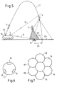
Figur 1- eine schematische Darstellung des Wurfsystems
Figur 2- eine dreidimensionale Ansicht des Wurfsystems mit einer Richtvorrichtung
Figur 3- eine schematische Darstellung der Funktion eines Laserbeleuchters
Figur 4- eine Seitenansicht des Splittergefechtskopfes teilweise in einem Längschnitt
Figur 5- in einer schematischen Darstellung den Funktionsablauf des Wurfsystems
Figur 6- einen Querschnitt des Gefechtskopfes mit einer Anordnung der Mikroreaktionstriebwerke
Figur 7- eine schematische Darstellung der möglichen Auslenkungen des Gefechtskopfes beim Korrekturvorgang
- Figure 1
- a schematic representation of the throwing system
- Figure 2
- a three-dimensional view of the throwing system with a straightening device
- Figure 3
- a schematic representation of the function of a laser illuminator
- Figure 4
- a side view of the fragmentation warhead partially in a longitudinal section
- Figure 5
- the functional sequence of the throwing system in a schematic representation
- Figure 6
- a cross section of the warhead with an arrangement of the microreaction engines
- Figure 7
- a schematic representation of the possible deflections of the warhead during the correction process
Das erfindungsgemäße Wurfsystem ermöglicht die Realisierung eines Rüstkit
das aus den Teilbereichen Wurfsystem 20 mit Richteinrichtung 21,
Laserbeleuchter 7 und Splittergefechtskopf 3 besteht.The throwing system according to the invention enables the implementation of a set-up kit
that from the sub-areas of throwing
Die Figuren 1 und 2 verdeutlichen das Wurfsystem 20 mit Richtvorrichtung 21
zur präzisen Verbringung des Splittergefechtskopfes 3. Die Richtvorrichtung 21
ermöglicht eine Ausrichtung des Wurfsystems 20 in Azimuthrichtung 22 in einem
Bereich von ca. 0 bis 180 Grad und in Elevationsrichtung 23 in einem Bereich
von ca. 60 bis 80 Grad. Eine Transportstellung mit 0 Grad ist vorgesehen.Figures 1 and 2 illustrate the throwing
Da die typische Einsatzreichweite ca. 20 bis 100 m beträgt, kann das
Wurfsystem 20 vorzugsweise als Federwurfsystem ausgeführt werden, das
gegenüber pyrotechnischen Verbringungsmechanismen deutlich geringere
Streuungen der Sollflugbahn ermöglicht.Since the typical operating range is approx. 20 to 100 m, this can be done
Throwing
Das Prinzip besteht darin, Federn 1 mittels Elektromotoren 2 so weit zu spannen,
dass bei Freigabe der Federn 1 der Splittergefechtskopf 3 eine genau
vorwählbare Anfangsgeschwindigkeit erhält. Der Kraft- / Wegverlauf der Federn
1, der dieser Energie entspricht, kann für die Regelung des Spannvorganges
durch Elektromotoren 2 präzise über Kraftelemente oder Stromsensoren 4 in der
Stromversorgung der E-Motoren 2 gemessen werden. Damit können auch
Einflüsse durch Temperatur und Materialermüdung in den Federn 2 weitgehend
ausgeglichen werden. Da eine gasdichte Führung des Splittergefechtskopfes 3
entfällt, kann der Splittergefechtskopf 3 z. B. in einem Becher 5, der durch die
Federn 1 über eine spielfreie Rollenführung 6 beschleunigt wird, mit geringer
Abgangsstreuung ausgeworfen werden.The principle is to tension springs 1 by means of
Der in der Figur 3 dargestellte Laserbeleuchter 7 kann zwei Laserstrahlen 8, 9
voneinander unabhängig frei positionierbar in Azimuth und Elevation aussenden,
wobei der Laserbeleuchter 7 auf einem Fahrzeug 19 positioniert ist.The
Der erste Laserstrahl 8 dient zur Beleuchtung einer Mine 10 oder einer
Oberflächenposition, unter der sich die Mine 10 befindet. Der Laserstrahl 8 kann
durch die Fahrzeugbesatzung über manuelles Richten einer Zielmarke auf die
erkannte Mine 10 geführt werden oder automatisch über eine nicht näher
dargestellte Steuereinheit gerichtet werden. Für diese automatische Steuerung
sind dann die genaue Position der Mine und die genaue Position sowie Richtung
des Fahrzeuges 19 erforderlich.The
Der zweite Laserstrahl 9 hat die Form eines Fächers. Elevations- und
Azimuthwinkel werden mit Bezug auf die Raumlage des
Beleuchtungslaserstrahls 8 automatisch ermittelt. Der Azimuthwinkel der
Mittellinie des Fächers entspricht dem Azimuthwinkel des Beleuchtungslasers 8,
der Elevationswinkel ist um einen solchen Wert größer als der Elevationswinkel
des Beleuchtungslasers 8, so dass der Strahlfächer 9 in einem vorwählbaren
Abstand 28, der beispielsweise 2- 4 m beträgt, über der Beleuchtungsposition
29 der Mine 10 verläuft. Dieser Laserstrahl 9 ist codiert.The
Nach den Figuren 4 - 7 besteht der Splittergefechtskopf 3 aus folgenden
Baugruppen: Einem Gefechtskopfkörper 11, einer Splitterladung 12, einem an
der Stirnseite des Splittergefechtskopfes 3 angeordneten Laserpositionsdetektor
13, der die Position des Laserleuchtflecks 29 des Beleuchtungslasers 8
bestimmt, einem Laserdetektor 14 mit Decodiereinrichtung zur Detektion des
codierten Laserfächers 9, drei Mikroreaktionstriebwerke 15 mit Zündeinrichtung,
die am Umfana des Gefechtskopfes um ie 120 Grad versetzt angebracht sind.
und einer Steuer- und Auswerteeinheit 16, welche die Steuerung des
Laserpositionsdetektors 13, des Laserdetektors 14, der Mikroreaktionstriebwerke
15, sowie die Zündung des Gefechtskopfes bewirkt.According to FIGS. 4-7, the
Das Wurfsystem funktioniert wie folgt:The throwing system works as follows:
Die Elektronik- und Zündeinrichtung des Gefechtskopfes 3 wird durch den
Wurfvorgang aktiviert. Ca. 3m über dem Boden 24 taucht der Gefechtskopf 3
durch den Laserfächer 9. Dieses Ereignis wird durch den Laserdetektor 14 mit
Decodiereinrichtung detektiert. Dadurch wird der Laserpositionsdetektor 13 an
der Stirnseite des Gefechtskopfes 3 eingeschaltet, der die Richtung des
Aufschlagpunktes 25 zum Beleuchtungspunkt 29 der Mine 10 misst. Die
Richtung wird lediglich als Sektor bestimmt. Die Anzahl der Sektoren bestimmt
sich durch die Anzahl der Mikroreaktionstriebwerke 15. Bei drei am Umfang 17
gleich verteilten Mikroreaktionstriebwerken 15 können durch Zündung von einem
oder zwei Triebwerken 15 insgesamt sechs um jeweils 60 Grad versetzte
Auslenkungen 18 erzielt werden. Damit ist eine Auflösung des Suchbereichs in
sechs Richtungssegmente mit je 60 Grad erforderlich, wenn abhängig vom
Segment ein oder zwei Mikroreaktionstriebwerke 15 gezündet werden.The electronics and ignition device of the
Der Laserpositionsdetektor 13 ermittelt, ob die Flugbahn 27 im Fleck 29 des
Beleuchtungslasers 8 mündet oder die Flugbahn 27 eine Ablage 26 aufweist. Ist
eine Ablage 26 gegeben, wird der Winkel gemessen und die dazugehörigen ein
oder zwei Triebwerke 15 gezündet. Dadurch wird eine Korrektur der Flugbahn 27
in Richtung des Beleuchtungsflecks 10 bewirkt. Da die Höhe des Laserfächers 9
über der Erdoberfläche, sowie die Geschwindigkeit des Gefechtskopfes bekannt
ist, kann nach einer bestimmten Zeit, in der die Korrektur der Flugbahn
abgeschlossen ist, die Auslösung des Splittergefechtskopfes 3 ca. 1 m über dem
Boden erfolgen. Die nicht dargestellten Splitter werden dadurch in einer
angenäherten Gleichverteilung mit einer Geschwindigkeit von ca. 800 m / s nach
unten ausgestoßen. Die Auslösehöhe, die Ausstoßcharakteristik und die Zahl der
Splitter sind so gewählt, dass in einem Kreis von ca. einem Meter Durchmesser
eine Splitterdichte von 0,2 Splitter / cm 2 erzielt wird. Die kinetische Energie der
Splitter ist ausreichend, nach einer Durchdringung von 30 cm Erdboden die
Minen noch sicher zu zerstören. The
- 11
- Federfeather
- 22
- Elektromotorelectric motor
- 33
- SplittergefechtskopfFragmentation warhead
- 44
- Kraftelement / StromsensorForce element / current sensor
- 55
- Becher / AufnahmeCup / holder
- 66
- Rollenführungroller guide
- 77
- Laserbeleuchterlaser illuminator
- 88th
- Laserstrahllaser beam
- 99
- Laserstrahl / LaserfächerLaser beam / laser fan
- 1010
- Minemine
- 1111
- GefechtskopfkörperWarhead body
- 1212
- Splitterladungfragmentation charge
- 1313
- LaserpositionsdetektorLaser position detector
- 1414
- Laserdetektorlaser detector
- 1515
- MikroreaktionstriebwerkMicroreaction engine
- 1616
- Steuer- und AntriebseinheitControl and drive unit
- 1717
- Umfangscope
- 1818
- Auslenkungdeflection
- 1919
- Fahrzeugvehicle
- 2020
- WurfsystemProjection system
- 2121
- Richtvorrichtungstraightener
- 2222
- Azimuthrichtungazimuth
- 2323
- Elevationsrichtungelevation direction
- 2424
- Bodenground
- 2525
- Aufschlagpunktpoint of impact
- 2626
- Ablagefiling
- 2727
- Flugbahntrajectory
- 2828
- Abstanddistance
- 2929
- Leuchtfleck / BeleuchtungspunktIlluminated spot / lighting point
Claims (10)
dadurch gekennzeichnet, dass der Kraft- / Wegverlauf der Federn (1) für die Regelung des Spannvorganges durch die Elektromotoren (2) präzise durch Kraftelemente oder Stromsensoren (4) in der Stromversorgung der Elektromotoren (2) mess- und einstellbar ist.Throwing system according to claim 2,
characterized in that the force / displacement curve of the springs (1) for controlling the tensioning process by the electric motors (2) can be measured and adjusted precisely by force elements or current sensors (4) in the power supply of the electric motors (2).
gekennzeichnet durch eine becherförmige Aufnahme (5) für den Splittergefechtskopf (3), die innerhalb des Wurfsystems (20) in einer Rollenführung (6) gelagert ist und durch die Federn (1) auswerfbar ist. Throwing system according to one of claims 1-3,
characterized by a cup-shaped receptacle (5) for the fragmentation warhead (3), which is mounted within the throwing system (20) in a roller guide (6) and can be ejected by the springs (1).
dadurch gekennzeichnet, dass ein erster vom Laserbeleuchter (7) ausgesandter Laserstrahl (8) der Beleuchtung einer Mine (10) oder der Oberflächenposition, unter der sich die Mine (10) befindet, dient, wobei der Laserstrahl (8) manuell oder automatisch auf die erkannte Mine ausrichtbar ist.Throwing system according to claim 1,
characterized in that a first laser beam (8) emitted by the laser illuminator (7) serves to illuminate a mine (10) or the surface position under which the mine (10) is located, the laser beam (8) being directed manually or automatically onto the detected mine is alignable.
dadurch gekennzeichnet, dass ein zweiter vom Laserbeleuchter (7) ausgesandter und codierter Laserstrahl (9) die Form eines Fächers aufweist, wobei der Azimuthwinkel der Mittellinie des Fächers dem Azimuthwinkel des Beleuchtungslasers und der Elevationswinkel um einen solchen Wert größer als der Elevationswinkel des Beleuchtungslasers entspricht, so dass der Strahlenfächer in einem annähernd konstanten vorwählbaren Abstand (28) über der Beleuchtungsposition (29) der Mine (10) verläuft.Throwing system according to claim 1,
characterized in that a second laser beam (9) emitted and coded by the laser illuminator (7) has the shape of a fan, the azimuth angle of the center line of the fan corresponding to the azimuth angle of the illumination laser and the elevation angle being greater than the elevation angle of the illumination laser, so that the beam fan runs at an approximately constant preselectable distance (28) above the lighting position (29) of the mine (10).
gekennzeichnet durch einen an der Stirnseite des Splittergefechtskopfes (3) angeordneten Laserpositionsdetektor (13) und einen heckseitig am Splittergefechtskopf (3) angeordneten Laserdetektor (14) mit einer Decodiereinrichtung zur Detektion des codierten Laserfächers (9).Throwing system according to one of claims 1-6,
characterized by a laser position detector (13) arranged on the front side of the fragmentation warhead (3) and a laser detector (14) arranged on the rear side of the fragmentation warhead (3) with a decoding device for detecting the coded laser fan (9).
dadurch gekennzeichnet, dass der Splittergefechtskopf (3) vorzugsweise auf dem Umfang (17) gleichmäßig verteilt angeordnete Mikroreaktionstriebwerke (15) mit einer Zündvorrichtung enthält.Throwing system according to one of claims 1-7,
characterized in that the fragmentation warhead (3) preferably contains micro-reaction engines (15) with an ignition device that are arranged uniformly distributed over the circumference (17).
dadurch gekennzeichnet, dass in dem Splittergefechtskopf (3) eine Steuer- und Antriebseinheit (16) angeordnet ist, durch die der Laserpositionsdetektor (13), der Laserdetektor (14), die Mikroreaktionstriebwerke (15) und die Zündung des Gefechtskopfes steuerbar ist. Throwing system according to one of claims 1-8,
characterized in that a control and drive unit (16) is arranged in the splinter warhead (3), by means of which the laser position detector (13), the laser detector (14), the microreaction engines (15) and the ignition of the warhead can be controlled.
dadurch gekennzeichnet, dass bei drei am Umfang (17) gleich verteilten Mikroreaktionstriebwerken (15) durch Zündung von einem oder zwei Triebwerken insgesamt sechs um jeweils 60° versetzte Auslenkungen (18) erzielbar sind, die eine Korrektur der Flugbahn (27) in Richtung des Beleuchtungsflecks (29) der Mine (10) bewirken.Throwing system according to one of claims 1-9,
characterized in that with three microreaction engines (15) equally distributed on the circumference (17), by igniting one or two engines, a total of six deflections (18), each offset by 60 °, can be achieved, which correct the trajectory (27) in the direction of the illumination spot (29) cause the mine (10).
Applications Claiming Priority (2)
| Application Number | Priority Date | Filing Date | Title |
|---|---|---|---|
| DE10147837A DE10147837A1 (en) | 2001-09-27 | 2001-09-27 | Warhead throwing system with a mine neutralizer |
| DE10147837 | 2001-09-27 |
Publications (2)
| Publication Number | Publication Date |
|---|---|
| EP1298409A1 true EP1298409A1 (en) | 2003-04-02 |
| EP1298409B1 EP1298409B1 (en) | 2006-03-08 |
Family
ID=7700602
Family Applications (1)
| Application Number | Title | Priority Date | Filing Date |
|---|---|---|---|
| EP02017902A Expired - Lifetime EP1298409B1 (en) | 2001-09-27 | 2002-08-09 | A system for launching a war head with a trajectory correction device for neutralisation of mines |
Country Status (6)
| Country | Link |
|---|---|
| US (1) | US6662701B2 (en) |
| EP (1) | EP1298409B1 (en) |
| AT (1) | ATE319977T1 (en) |
| DE (2) | DE10147837A1 (en) |
| DK (1) | DK1298409T3 (en) |
| ES (1) | ES2258124T3 (en) |
Cited By (2)
| Publication number | Priority date | Publication date | Assignee | Title |
|---|---|---|---|---|
| WO2007011398A2 (en) * | 2004-10-21 | 2007-01-25 | Deka Products Limited Partnership | Controllable launcher |
| CN114877761A (en) * | 2021-09-26 | 2022-08-09 | 中国人民解放军63921部队 | Deep-cut inert projectile target field flight test method based on natural rock environment |
Families Citing this family (6)
| Publication number | Priority date | Publication date | Assignee | Title |
|---|---|---|---|---|
| WO2003087702A1 (en) * | 2002-04-12 | 2003-10-23 | Euronord S.A.S. Di G.B. Marcolla & C. | Mine removing system |
| DE102004046571A1 (en) * | 2004-09-24 | 2006-04-06 | Rheinmetall Landsysteme Gmbh | Device for carrying a payload, in particular for neutralizing mines or the like |
| FR3050814B1 (en) * | 2016-04-29 | 2019-06-07 | Airbus Helicopters | METHOD AND DEVICE FOR ASSISTED AID FOR LASER GUIDANCE OF A PROJECTILE |
| DE102016113521A1 (en) | 2016-07-21 | 2018-01-25 | Rheinmetall Landsysteme Gmbh | bullet |
| US10151555B1 (en) * | 2017-06-08 | 2018-12-11 | Bell Helicopter Textron Inc. | Air cannon with sabot system |
| US10746495B1 (en) * | 2019-08-28 | 2020-08-18 | The United States Of America As Represented By The Secretary Of The Navy | Catapult launcher |
Citations (4)
| Publication number | Priority date | Publication date | Assignee | Title |
|---|---|---|---|---|
| US3860199A (en) * | 1972-01-03 | 1975-01-14 | Ship Systems Inc | Laser-guided projectile system |
| US4176814A (en) * | 1976-04-02 | 1979-12-04 | Ab Bofors | Terminally corrected projectile |
| US4431147A (en) * | 1981-12-24 | 1984-02-14 | The Bendix Corporation | Steerable artillery projectile |
| WO2001016547A2 (en) * | 1999-07-21 | 2001-03-08 | Primex Technologies, Inc. | Ring array projectile steering with optically-triggered diverter elements |
Family Cites Families (31)
| Publication number | Priority date | Publication date | Assignee | Title |
|---|---|---|---|---|
| US3116039A (en) * | 1956-02-29 | 1963-12-31 | Goldberg Michael | Method of and system for guiding a missile |
| US3998406A (en) * | 1964-05-28 | 1976-12-21 | Aeronutronic Ford Corporation | Guided missile system |
| US3743216A (en) * | 1969-01-09 | 1973-07-03 | Us Army | Homing missile system using laser illuminator |
| US4143835A (en) * | 1972-09-12 | 1979-03-13 | The United States Of America As Represented By The Secretary Of The Army | Missile system using laser illuminator |
| US5350134A (en) * | 1973-07-03 | 1994-09-27 | Gec Ferranti Defence Systems Limited | Target identification systems |
| US3924600A (en) * | 1973-07-20 | 1975-12-09 | Geroge C Luebkeman | Throwing arm latch for spring target traps |
| FR2279062A1 (en) * | 1974-01-02 | 1976-02-13 | Laporte Jean Michel | PLATFORM LAUNCHING DEVICE FOR SHOOTING |
| US3974383A (en) * | 1975-02-03 | 1976-08-10 | Hughes Aircraft Company | Missile tracking and guidance system |
| DE2803036A1 (en) * | 1978-01-25 | 1979-07-26 | Messerschmitt Boelkow Blohm | ARTICULATED BOMB FOR DEEP FLIGHT DEPLOYMENT |
| US4300736A (en) * | 1979-08-17 | 1981-11-17 | Raytheon Company | Fire control system |
| DE2947492C2 (en) * | 1979-11-24 | 1983-04-28 | Licentia Patent-Verwaltungs-Gmbh, 6000 Frankfurt | Guidance methods for missiles |
| DE2951941C2 (en) * | 1979-12-22 | 1988-01-21 | Diehl GmbH & Co, 8500 Nürnberg | Optical remote control device for a projectile |
| CA1180085A (en) * | 1980-11-21 | 1984-12-27 | Michel M. Fortier | Laser-guided bomb trainer |
| US4678143A (en) * | 1982-12-17 | 1987-07-07 | Frazer-Nash Ltd. | Launcher for remotely piloted aircraft |
| US4624424A (en) * | 1984-11-07 | 1986-11-25 | The Boeing Company | On-board flight control drag actuator system |
| DE3441921A1 (en) * | 1984-11-16 | 1986-05-28 | Messerschmitt-Bölkow-Blohm GmbH, 8012 Ottobrunn | GUIDE AND FOLLOW-UP DEVICE |
| FR2627268B1 (en) * | 1988-02-12 | 1993-05-14 | Thomson Brandt Armements | LASER BEAM VECTOR GUIDANCE SYSTEM AND PYROTECHNIC IMPELLERS, AND VECTOR GUIDED BY SUCH A SYSTEM |
| US5102065A (en) * | 1988-02-17 | 1992-04-07 | Thomson - Csf | System to correct the trajectory of a projectile |
| US5011097A (en) * | 1990-08-30 | 1991-04-30 | The United States Of America As Represented By The Secretary Of The Navy | Vehicle steering device |
| DE4035325A1 (en) * | 1990-11-07 | 1992-05-14 | Wegmann & Co | Missile or shell range control - by selective ignition of propellant charges in firing system |
| FR2669108B1 (en) * | 1990-11-09 | 1997-01-03 | Thomson Csf | OPTICAL DEVICE FOR MEASURING THE ROLL ANGLE OF A PROJECTILE. |
| DE4128313C2 (en) * | 1991-08-27 | 2000-04-20 | Diehl Stiftung & Co | Guided missile for warhead defense |
| DE4325218C2 (en) * | 1993-07-28 | 1998-10-22 | Diehl Stiftung & Co | Artillery missile and method for increasing the performance of an artillery missile |
| DE4416211C2 (en) * | 1994-05-07 | 1996-09-26 | Rheinmetall Ind Gmbh | Method and device for missile trajectory correction |
| DE4425285C2 (en) * | 1994-07-16 | 1997-04-17 | Rheinmetall Ind Ag | Device for the trajectory correction of spin-stabilized projectiles |
| US5458041A (en) * | 1994-08-02 | 1995-10-17 | Northrop Grumman Corporation | Air defense destruction missile weapon system |
| US6062207A (en) * | 1996-05-29 | 2000-05-16 | Underhill; Clinton James | Target trap foot operated cocking and releasing device |
| US5695152A (en) * | 1996-09-18 | 1997-12-09 | Israel Aircraft Industries Ltd. | System for correcting flight trajectory of a projectile |
| US5831724A (en) * | 1997-07-22 | 1998-11-03 | The United States Of America As Represented By The Secretary Of The Navy | Imaging lidar-based aim verification method and system |
| US5988038A (en) * | 1998-01-22 | 1999-11-23 | Raytheon Company | Method and apparatus for destroying buried objects |
| US6422507B1 (en) * | 1999-07-02 | 2002-07-23 | Jay Lipeles | Smart bullet |
-
2001
- 2001-09-27 DE DE10147837A patent/DE10147837A1/en not_active Withdrawn
-
2002
- 2002-08-09 DK DK02017902T patent/DK1298409T3/en active
- 2002-08-09 AT AT02017902T patent/ATE319977T1/en not_active IP Right Cessation
- 2002-08-09 EP EP02017902A patent/EP1298409B1/en not_active Expired - Lifetime
- 2002-08-09 ES ES02017902T patent/ES2258124T3/en not_active Expired - Lifetime
- 2002-08-09 DE DE50205991T patent/DE50205991D1/en not_active Expired - Lifetime
- 2002-09-25 US US10/253,611 patent/US6662701B2/en not_active Expired - Fee Related
Patent Citations (4)
| Publication number | Priority date | Publication date | Assignee | Title |
|---|---|---|---|---|
| US3860199A (en) * | 1972-01-03 | 1975-01-14 | Ship Systems Inc | Laser-guided projectile system |
| US4176814A (en) * | 1976-04-02 | 1979-12-04 | Ab Bofors | Terminally corrected projectile |
| US4431147A (en) * | 1981-12-24 | 1984-02-14 | The Bendix Corporation | Steerable artillery projectile |
| WO2001016547A2 (en) * | 1999-07-21 | 2001-03-08 | Primex Technologies, Inc. | Ring array projectile steering with optically-triggered diverter elements |
Cited By (5)
| Publication number | Priority date | Publication date | Assignee | Title |
|---|---|---|---|---|
| WO2007011398A2 (en) * | 2004-10-21 | 2007-01-25 | Deka Products Limited Partnership | Controllable launcher |
| WO2007011398A3 (en) * | 2004-10-21 | 2007-05-10 | Deka Products Lp | Controllable launcher |
| US8061343B2 (en) | 2004-10-21 | 2011-11-22 | Deka Products Limited Partnership | Controllable launcher |
| CN114877761A (en) * | 2021-09-26 | 2022-08-09 | 中国人民解放军63921部队 | Deep-cut inert projectile target field flight test method based on natural rock environment |
| CN114877761B (en) * | 2021-09-26 | 2023-11-07 | 中国人民解放军63921部队 | Deep-invasion inert bomb range flight test method based on natural rock environment |
Also Published As
| Publication number | Publication date |
|---|---|
| US20030126979A1 (en) | 2003-07-10 |
| DE10147837A1 (en) | 2003-04-24 |
| ATE319977T1 (en) | 2006-03-15 |
| DK1298409T3 (en) | 2006-04-18 |
| DE50205991D1 (en) | 2006-05-04 |
| US6662701B2 (en) | 2003-12-16 |
| ES2258124T3 (en) | 2006-08-16 |
| EP1298409B1 (en) | 2006-03-08 |
Similar Documents
| Publication | Publication Date | Title |
|---|---|---|
| DE10346001B4 (en) | Device for protecting ships from end-phase guided missiles | |
| EP2118615B1 (en) | Method and device for defence against airborne threads | |
| EP0971199A1 (en) | Device for the destruction of warheads | |
| DE19642091A1 (en) | Protection device for armored vehicles | |
| EP1298409B1 (en) | A system for launching a war head with a trajectory correction device for neutralisation of mines | |
| DE2905422A1 (en) | DEVICE FOR SHOT SIMULATION WITH HIT INDICATOR | |
| DE3705383C2 (en) | ||
| DE112012004949T5 (en) | Splitter jet-tank projectile | |
| DE4029898C2 (en) | ||
| DE3013405C2 (en) | Method of avoiding messaging from ballistic missile launchers | |
| WO1986006470A1 (en) | Process for operating a proximity fuse, and device for the implementation of the process | |
| DE19729483A1 (en) | Air-born land mine retrieval method | |
| EP0708305B1 (en) | Method for protecting radiation emitting devices from missiles, in particular infrared radiation emitting devices such as ships | |
| DE3123339A1 (en) | Method for remote detonation of an explosive projectile, especially of an anti-helicopter projectile, and a device and projectile for carrying out the method | |
| DE3543769A1 (en) | Mine for defence against moving objects | |
| EP0281675A2 (en) | Sensor for attacking helicopters | |
| DE3326748C2 (en) | ||
| DE19617060C2 (en) | Method and device for simulating the effects of steep arms on combat units | |
| DE2922592A1 (en) | METHOD FOR DEFENDING AIRCASE | |
| DE102018131524A1 (en) | Process for protecting moving or immovable objects from approaching laser-guided threats | |
| DE102015000871A1 (en) | Mine clearing machine and mine clearance method | |
| DE3904293A1 (en) | Area weapon | |
| EP2989408B1 (en) | Method for operating a weapon system | |
| DE3938798C1 (en) | Low flying or hovering aircraft combating - laying out probes with sensors along typical flight path, and launching light signal on detection of aircraft, marking its position | |
| DE4327214C1 (en) | Laying device for penetrators having built-in sensors |
Legal Events
| Date | Code | Title | Description |
|---|---|---|---|
| PUAI | Public reference made under article 153(3) epc to a published international application that has entered the european phase |
Free format text: ORIGINAL CODE: 0009012 |
|
| 17P | Request for examination filed |
Effective date: 20021219 |
|
| AK | Designated contracting states |
Kind code of ref document: A1 Designated state(s): AT BE BG CH CY CZ DE DK EE ES FI FR GB GR IE IT LI LU MC NL PT SE SK TR Designated state(s): AT BE BG CH CY CZ DE DK EE ES FI FR GB GR IE IT LI LU MC NL PT SE SK TR |
|
| AX | Request for extension of the european patent |
Extension state: AL LT LV MK RO SI |
|
| AKX | Designation fees paid |
Designated state(s): AT BE BG CH CY CZ DE DK EE ES FI FR GB GR IE IT LI LU MC NL PT SE SK TR |
|
| GRAP | Despatch of communication of intention to grant a patent |
Free format text: ORIGINAL CODE: EPIDOSNIGR1 |
|
| RAP1 | Party data changed (applicant data changed or rights of an application transferred) |
Owner name: RHEINMETALL LANDSYSTEME GMBH |
|
| GRAS | Grant fee paid |
Free format text: ORIGINAL CODE: EPIDOSNIGR3 |
|
| GRAA | (expected) grant |
Free format text: ORIGINAL CODE: 0009210 |
|
| AK | Designated contracting states |
Kind code of ref document: B1 Designated state(s): AT BE BG CH CY CZ DE DK EE ES FI FR GB GR IE IT LI LU MC NL PT SE SK TR |
|
| PG25 | Lapsed in a contracting state [announced via postgrant information from national office to epo] |
Ref country code: SK Free format text: LAPSE BECAUSE OF FAILURE TO SUBMIT A TRANSLATION OF THE DESCRIPTION OR TO PAY THE FEE WITHIN THE PRESCRIBED TIME-LIMIT Effective date: 20060308 Ref country code: IE Free format text: LAPSE BECAUSE OF FAILURE TO SUBMIT A TRANSLATION OF THE DESCRIPTION OR TO PAY THE FEE WITHIN THE PRESCRIBED TIME-LIMIT Effective date: 20060308 Ref country code: FI Free format text: LAPSE BECAUSE OF FAILURE TO SUBMIT A TRANSLATION OF THE DESCRIPTION OR TO PAY THE FEE WITHIN THE PRESCRIBED TIME-LIMIT Effective date: 20060308 |
|
| REG | Reference to a national code |
Ref country code: GB Ref legal event code: FG4D Free format text: NOT ENGLISH |
|
| REG | Reference to a national code |
Ref country code: CH Ref legal event code: EP |
|
| GBT | Gb: translation of ep patent filed (gb section 77(6)(a)/1977) |
Effective date: 20060308 |
|
| REG | Reference to a national code |
Ref country code: IE Ref legal event code: FG4D Free format text: LANGUAGE OF EP DOCUMENT: GERMAN |
|
| REG | Reference to a national code |
Ref country code: DK Ref legal event code: T3 |
|
| REF | Corresponds to: |
Ref document number: 50205991 Country of ref document: DE Date of ref document: 20060504 Kind code of ref document: P |
|
| REG | Reference to a national code |
Ref country code: SE Ref legal event code: TRGR |
|
| PG25 | Lapsed in a contracting state [announced via postgrant information from national office to epo] |
Ref country code: BG Free format text: LAPSE BECAUSE OF FAILURE TO SUBMIT A TRANSLATION OF THE DESCRIPTION OR TO PAY THE FEE WITHIN THE PRESCRIBED TIME-LIMIT Effective date: 20060608 |
|
| PG25 | Lapsed in a contracting state [announced via postgrant information from national office to epo] |
Ref country code: PT Free format text: LAPSE BECAUSE OF FAILURE TO SUBMIT A TRANSLATION OF THE DESCRIPTION OR TO PAY THE FEE WITHIN THE PRESCRIBED TIME-LIMIT Effective date: 20060808 |
|
| PGFP | Annual fee paid to national office [announced via postgrant information from national office to epo] |
Ref country code: DK Payment date: 20060815 Year of fee payment: 5 |
|
| REG | Reference to a national code |
Ref country code: ES Ref legal event code: FG2A Ref document number: 2258124 Country of ref document: ES Kind code of ref document: T3 |
|
| PG25 | Lapsed in a contracting state [announced via postgrant information from national office to epo] |
Ref country code: MC Free format text: LAPSE BECAUSE OF NON-PAYMENT OF DUE FEES Effective date: 20060831 Ref country code: LI Free format text: LAPSE BECAUSE OF NON-PAYMENT OF DUE FEES Effective date: 20060831 Ref country code: CH Free format text: LAPSE BECAUSE OF NON-PAYMENT OF DUE FEES Effective date: 20060831 |
|
| ET | Fr: translation filed | ||
| PGFP | Annual fee paid to national office [announced via postgrant information from national office to epo] |
Ref country code: BE Payment date: 20060914 Year of fee payment: 5 |
|
| REG | Reference to a national code |
Ref country code: IE Ref legal event code: FD4D |
|
| PLBE | No opposition filed within time limit |
Free format text: ORIGINAL CODE: 0009261 |
|
| STAA | Information on the status of an ep patent application or granted ep patent |
Free format text: STATUS: NO OPPOSITION FILED WITHIN TIME LIMIT |
|
| 26N | No opposition filed |
Effective date: 20061211 |
|
| REG | Reference to a national code |
Ref country code: CH Ref legal event code: PL |
|
| PG25 | Lapsed in a contracting state [announced via postgrant information from national office to epo] |
Ref country code: AT Free format text: LAPSE BECAUSE OF NON-PAYMENT OF DUE FEES Effective date: 20060809 |
|
| BERE | Be: lapsed |
Owner name: *RHEINMETALL LANDSYSTEME G.M.B.H. Effective date: 20070831 |
|
| REG | Reference to a national code |
Ref country code: DK Ref legal event code: EBP |
|
| PG25 | Lapsed in a contracting state [announced via postgrant information from national office to epo] |
Ref country code: GR Free format text: LAPSE BECAUSE OF FAILURE TO SUBMIT A TRANSLATION OF THE DESCRIPTION OR TO PAY THE FEE WITHIN THE PRESCRIBED TIME-LIMIT Effective date: 20060609 Ref country code: CZ Free format text: LAPSE BECAUSE OF FAILURE TO SUBMIT A TRANSLATION OF THE DESCRIPTION OR TO PAY THE FEE WITHIN THE PRESCRIBED TIME-LIMIT Effective date: 20060308 |
|
| PG25 | Lapsed in a contracting state [announced via postgrant information from national office to epo] |
Ref country code: EE Free format text: LAPSE BECAUSE OF FAILURE TO SUBMIT A TRANSLATION OF THE DESCRIPTION OR TO PAY THE FEE WITHIN THE PRESCRIBED TIME-LIMIT Effective date: 20060308 |
|
| PG25 | Lapsed in a contracting state [announced via postgrant information from national office to epo] |
Ref country code: TR Free format text: LAPSE BECAUSE OF FAILURE TO SUBMIT A TRANSLATION OF THE DESCRIPTION OR TO PAY THE FEE WITHIN THE PRESCRIBED TIME-LIMIT Effective date: 20060308 Ref country code: LU Free format text: LAPSE BECAUSE OF NON-PAYMENT OF DUE FEES Effective date: 20060809 Ref country code: DK Free format text: LAPSE BECAUSE OF NON-PAYMENT OF DUE FEES Effective date: 20070831 |
|
| PG25 | Lapsed in a contracting state [announced via postgrant information from national office to epo] |
Ref country code: BE Free format text: LAPSE BECAUSE OF NON-PAYMENT OF DUE FEES Effective date: 20070831 |
|
| REG | Reference to a national code |
Ref country code: ES Ref legal event code: FD2A Effective date: 20070810 |
|
| PG25 | Lapsed in a contracting state [announced via postgrant information from national office to epo] |
Ref country code: CY Free format text: LAPSE BECAUSE OF FAILURE TO SUBMIT A TRANSLATION OF THE DESCRIPTION OR TO PAY THE FEE WITHIN THE PRESCRIBED TIME-LIMIT Effective date: 20060308 |
|
| PG25 | Lapsed in a contracting state [announced via postgrant information from national office to epo] |
Ref country code: ES Free format text: LAPSE BECAUSE OF NON-PAYMENT OF DUE FEES Effective date: 20070810 |
|
| PGFP | Annual fee paid to national office [announced via postgrant information from national office to epo] |
Ref country code: SE Payment date: 20090813 Year of fee payment: 8 Ref country code: NL Payment date: 20090814 Year of fee payment: 8 Ref country code: GB Payment date: 20090827 Year of fee payment: 8 Ref country code: DE Payment date: 20090821 Year of fee payment: 8 |
|
| PGFP | Annual fee paid to national office [announced via postgrant information from national office to epo] |
Ref country code: IT Payment date: 20090819 Year of fee payment: 8 |
|
| REG | Reference to a national code |
Ref country code: NL Ref legal event code: V1 Effective date: 20110301 |
|
| EUG | Se: european patent has lapsed | ||
| GBPC | Gb: european patent ceased through non-payment of renewal fee |
Effective date: 20100809 |
|
| REG | Reference to a national code |
Ref country code: FR Ref legal event code: ST Effective date: 20110502 |
|
| PG25 | Lapsed in a contracting state [announced via postgrant information from national office to epo] |
Ref country code: NL Free format text: LAPSE BECAUSE OF NON-PAYMENT OF DUE FEES Effective date: 20110301 Ref country code: IT Free format text: LAPSE BECAUSE OF NON-PAYMENT OF DUE FEES Effective date: 20100809 |
|
| REG | Reference to a national code |
Ref country code: DE Ref legal event code: R119 Ref document number: 50205991 Country of ref document: DE Effective date: 20110301 |
|
| PG25 | Lapsed in a contracting state [announced via postgrant information from national office to epo] |
Ref country code: DE Free format text: LAPSE BECAUSE OF NON-PAYMENT OF DUE FEES Effective date: 20110301 Ref country code: FR Free format text: LAPSE BECAUSE OF NON-PAYMENT OF DUE FEES Effective date: 20100831 |
|
| PG25 | Lapsed in a contracting state [announced via postgrant information from national office to epo] |
Ref country code: GB Free format text: LAPSE BECAUSE OF NON-PAYMENT OF DUE FEES Effective date: 20100809 |
|
| PGFP | Annual fee paid to national office [announced via postgrant information from national office to epo] |
Ref country code: FR Payment date: 20090914 Year of fee payment: 8 |
|
| PG25 | Lapsed in a contracting state [announced via postgrant information from national office to epo] |
Ref country code: SE Free format text: LAPSE BECAUSE OF NON-PAYMENT OF DUE FEES Effective date: 20100810 |