EP1298326A1 - Propeller fan, propeller fan molding mold, and fluid feeding device - Google Patents

Propeller fan, propeller fan molding mold, and fluid feeding device Download PDF

Info

Publication number
EP1298326A1
EP1298326A1 EP01945810A EP01945810A EP1298326A1 EP 1298326 A1 EP1298326 A1 EP 1298326A1 EP 01945810 A EP01945810 A EP 01945810A EP 01945810 A EP01945810 A EP 01945810A EP 1298326 A1 EP1298326 A1 EP 1298326A1
Authority
EP
European Patent Office
Prior art keywords
propeller fan
blade
diameter
curved surface
coordinates
Prior art date
Legal status (The legal status is an assumption and is not a legal conclusion. Google has not performed a legal analysis and makes no representation as to the accuracy of the status listed.)
Granted
Application number
EP01945810A
Other languages
German (de)
French (fr)
Other versions
EP1298326A4 (en
EP1298326B1 (en
Inventor
Masaki Ohtsuka
Current Assignee (The listed assignees may be inaccurate. Google has not performed a legal analysis and makes no representation or warranty as to the accuracy of the list.)
Sharp Corp
Original Assignee
Sharp Corp
Priority date (The priority date is an assumption and is not a legal conclusion. Google has not performed a legal analysis and makes no representation as to the accuracy of the date listed.)
Filing date
Publication date
Priority claimed from JP2000202717A external-priority patent/JP3673148B2/en
Priority claimed from JP2000244268A external-priority patent/JP3673154B2/en
Priority claimed from JP2000256867A external-priority patent/JP3673156B2/en
Application filed by Sharp Corp filed Critical Sharp Corp
Priority to EP09004294A priority Critical patent/EP2085621B1/en
Priority to EP09004293A priority patent/EP2068001B1/en
Publication of EP1298326A1 publication Critical patent/EP1298326A1/en
Publication of EP1298326A4 publication Critical patent/EP1298326A4/en
Application granted granted Critical
Publication of EP1298326B1 publication Critical patent/EP1298326B1/en
Anticipated expiration legal-status Critical
Expired - Lifetime legal-status Critical Current

Links

Images

Classifications

    • FMECHANICAL ENGINEERING; LIGHTING; HEATING; WEAPONS; BLASTING
    • F04POSITIVE - DISPLACEMENT MACHINES FOR LIQUIDS; PUMPS FOR LIQUIDS OR ELASTIC FLUIDS
    • F04DNON-POSITIVE-DISPLACEMENT PUMPS
    • F04D29/00Details, component parts, or accessories
    • F04D29/26Rotors specially for elastic fluids
    • F04D29/32Rotors specially for elastic fluids for axial flow pumps
    • F04D29/38Blades
    • F04D29/384Blades characterised by form
    • BPERFORMING OPERATIONS; TRANSPORTING
    • B29WORKING OF PLASTICS; WORKING OF SUBSTANCES IN A PLASTIC STATE IN GENERAL
    • B29CSHAPING OR JOINING OF PLASTICS; SHAPING OF MATERIAL IN A PLASTIC STATE, NOT OTHERWISE PROVIDED FOR; AFTER-TREATMENT OF THE SHAPED PRODUCTS, e.g. REPAIRING
    • B29C45/00Injection moulding, i.e. forcing the required volume of moulding material through a nozzle into a closed mould; Apparatus therefor
    • B29C45/17Component parts, details or accessories; Auxiliary operations
    • B29C45/26Moulds
    • BPERFORMING OPERATIONS; TRANSPORTING
    • B29WORKING OF PLASTICS; WORKING OF SUBSTANCES IN A PLASTIC STATE IN GENERAL
    • B29LINDEXING SCHEME ASSOCIATED WITH SUBCLASS B29C, RELATING TO PARTICULAR ARTICLES
    • B29L2031/00Other particular articles
    • B29L2031/08Blades for rotors, stators, fans, turbines or the like, e.g. screw propellers
    • B29L2031/087Propellers
    • YGENERAL TAGGING OF NEW TECHNOLOGICAL DEVELOPMENTS; GENERAL TAGGING OF CROSS-SECTIONAL TECHNOLOGIES SPANNING OVER SEVERAL SECTIONS OF THE IPC; TECHNICAL SUBJECTS COVERED BY FORMER USPC CROSS-REFERENCE ART COLLECTIONS [XRACs] AND DIGESTS
    • Y10TECHNICAL SUBJECTS COVERED BY FORMER USPC
    • Y10STECHNICAL SUBJECTS COVERED BY FORMER USPC CROSS-REFERENCE ART COLLECTIONS [XRACs] AND DIGESTS
    • Y10S416/00Fluid reaction surfaces, i.e. impellers
    • Y10S416/02Formulas of curves

Definitions

  • the present invention relates to a propeller fan constituting a blower together with a drive motor; a molding die for the propeller fan; and a fluid feeding device provided with the blower, such as an outside unit of an air conditioner, an air cleaner, a humidifier, a dehumidifier, an electric fan, a fan heater, a cooling device, and a ventilator.
  • a fluid feeding device provided with the blower, such as an outside unit of an air conditioner, an air cleaner, a humidifier, a dehumidifier, an electric fan, a fan heater, a cooling device, and a ventilator.
  • a propeller fan is used in a blower or a cooler.
  • the outside unit of an air conditioner is provided with a propeller fan for cooling.
  • the propeller fan for cooling has conventionally had a problem such that it produces high noise at rotation and thus is inefficient. Airflow may be reduced to lower the noise, which then presents a problem of insufficient achievement of cooling effect.
  • the weight of the propeller fan may be made lighter, simply, by reducing the thickness of a blade.
  • flow tends to separate from the wing, causing a problem such that, in addition to that the noise is increased, the rigidity of the blade is lowered, a centrifugal force deforms the blade at the time of operation of the blower, which reduces the height of the fan in the axial direction, and thus the airflow is degraded.
  • the thickness of the blade root may partially be increased in order to increase the strength of the propeller fan.
  • the thickness of a part of the blade root is simply increased, cooling time at fabrication is increased to a large degree, raising the cost.
  • the present invention was made in view of the problems in the conventional example above, and an object of the present invention is to provide a propeller fan that can realize high airflow, high efficiency and low noise; a die for molding the same; and a fluid feeding device that can realize high airflow, high efficiency and low noise.
  • Another object of the present invention is to provide a propeller fan that can realize high airflow, high efficiency, low noise, light weight and low cost; a die for molding the same; and a fluid feeding device that can realize high airflow, high efficiency, low noise, light weight and low cost.
  • a further object of the present invention is to provide a propeller fan that can realize high airflow, high efficiency, low noise, light weight, low cost and increased strength; a die for molding the same; and a fluid feeding device that can realize high airflow, high efficiency, low noise, light weight, low cost and increased strength.
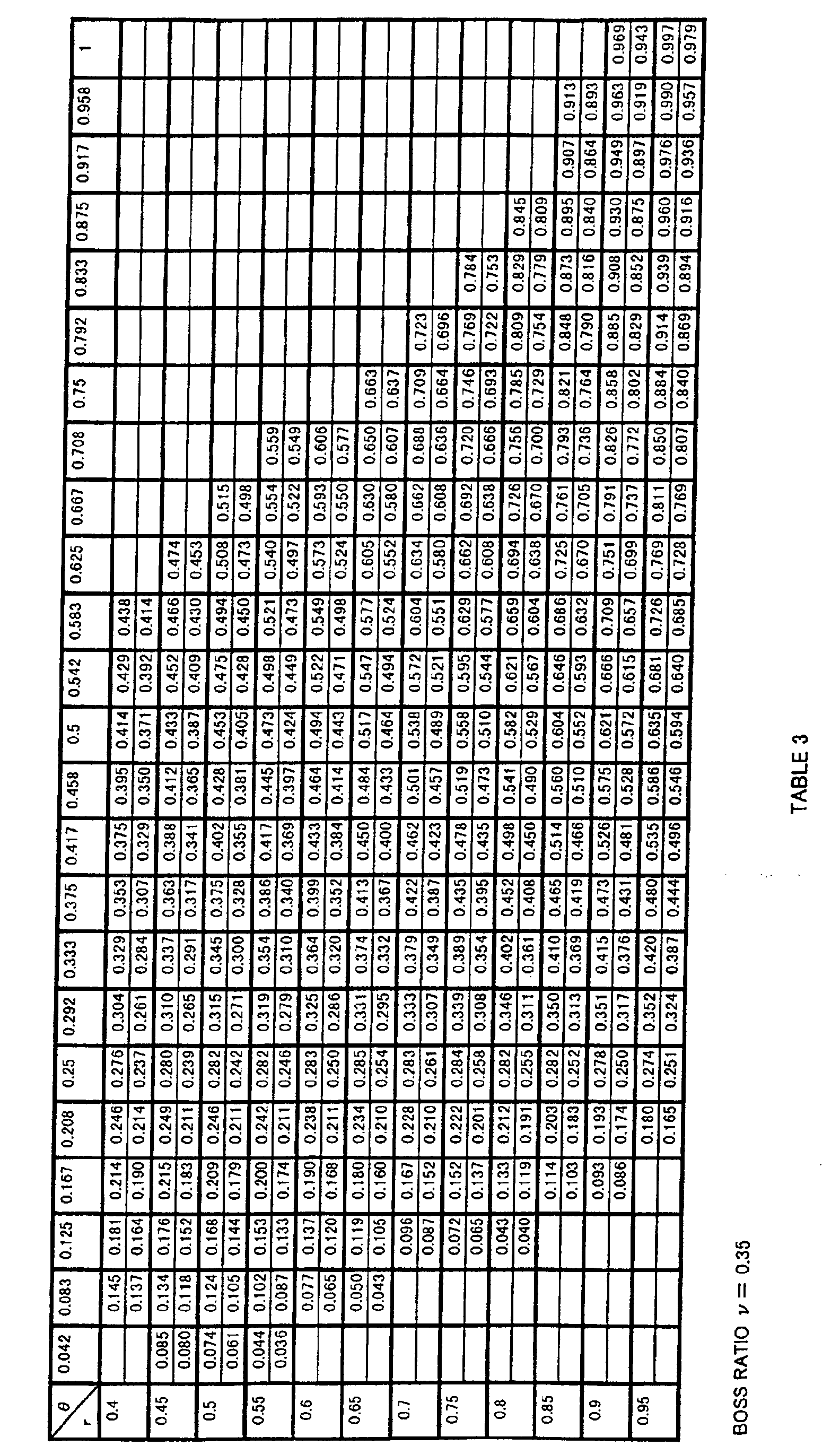
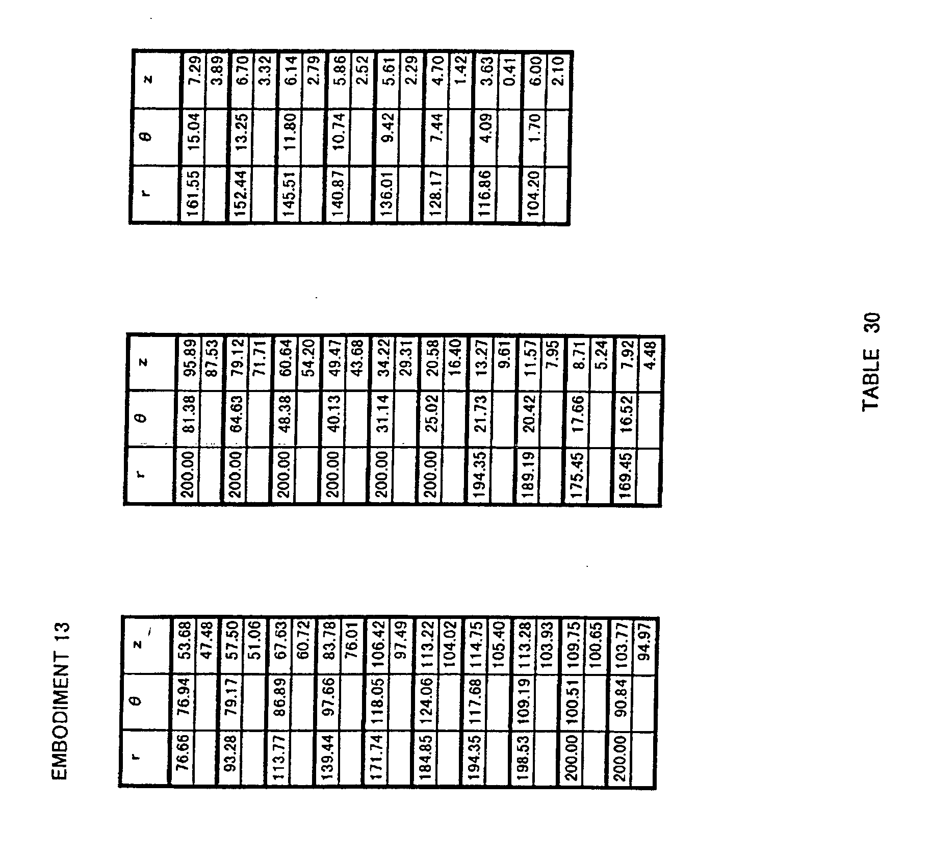
  • a curved shape defined by a r coordinate value, a ⁇ coordinate value and a z coordinate value indicated in Tables 3 and 4 below is determined as a base shape of the blade surface of the propeller fan, and the surface of the blade of the propeller fan is configured by a curved surface obtained by enlarging or reducing the base shape in at least one of r, ⁇ and z directions.
  • r indicates a non-dimensional r coordinate in the radial direction in the cylindrical coordinate system having the z axis as the rotation axis of the propeller fan
  • indicates a non-dimensional ⁇ coordinate in the circumferential direction in the cylindrical coordinate system having the z axis as the rotation axis of the propeller fan
  • z indicates a non-dimensional z coordinate in the axial direction (the direction of height) in the cylindrical coordinate system having the z axis as the rotation axis of the propeller fan.
  • each column (z u ) indicates a coordinate value on a negative pressure side (suction side) of the propeller fan
  • the bottom of each column (z d ) indicates a coordinate value on a positive pressure side (blowing side) thereof.
  • Table 3 indicates a non-dimensional coordinate value of z where r is within the range of 0.4 to 0.95 and where ⁇ is within the range of 0.042 to 1
  • Table 4 indicates non-dimensional coordinate values of r, ⁇ and z at an outer edge portion of a blade. It is noted that the contents of Table 1 are the same as those in Table 3, and the contents of Table 2 are the same as those in Table 4.
  • values within the range of ⁇ 5 % of the coordinate values calculated by transformation formulas of the present invention should be interpreted as included in a range of error and equivalent to the coordinate values of the present invention.
  • shape defined by the coordinate values within the range of ⁇ 5 % of the coordinate values calculated by transformation formulas of the present invention should be interpreted as included in a technical range of the present invention.
  • the surface of a portion forming the surface of a blade of the propeller fan is configured by a curved surface obtained by enlarging or reducing the base shape in at least one of r, ⁇ and z directions.
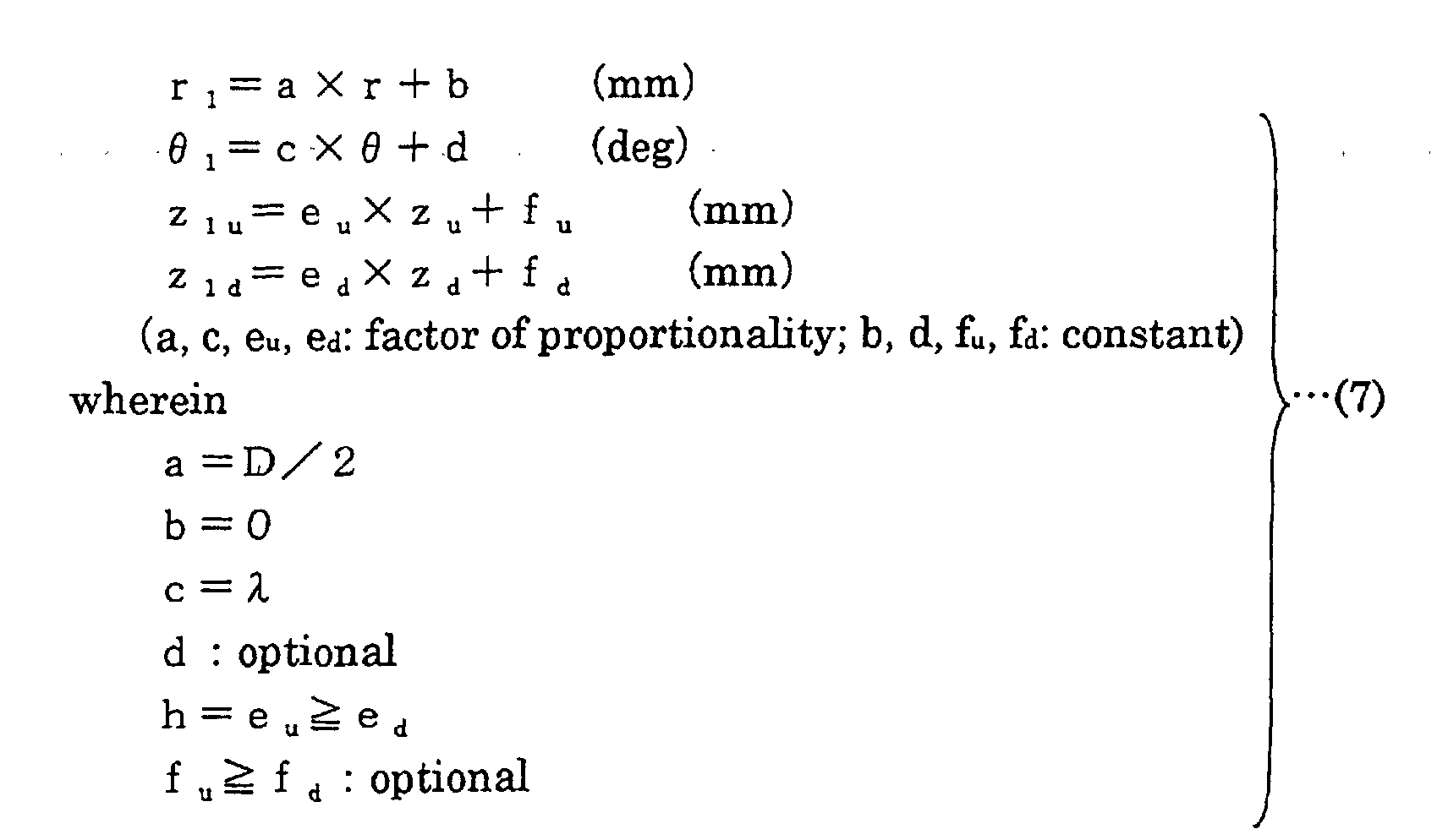
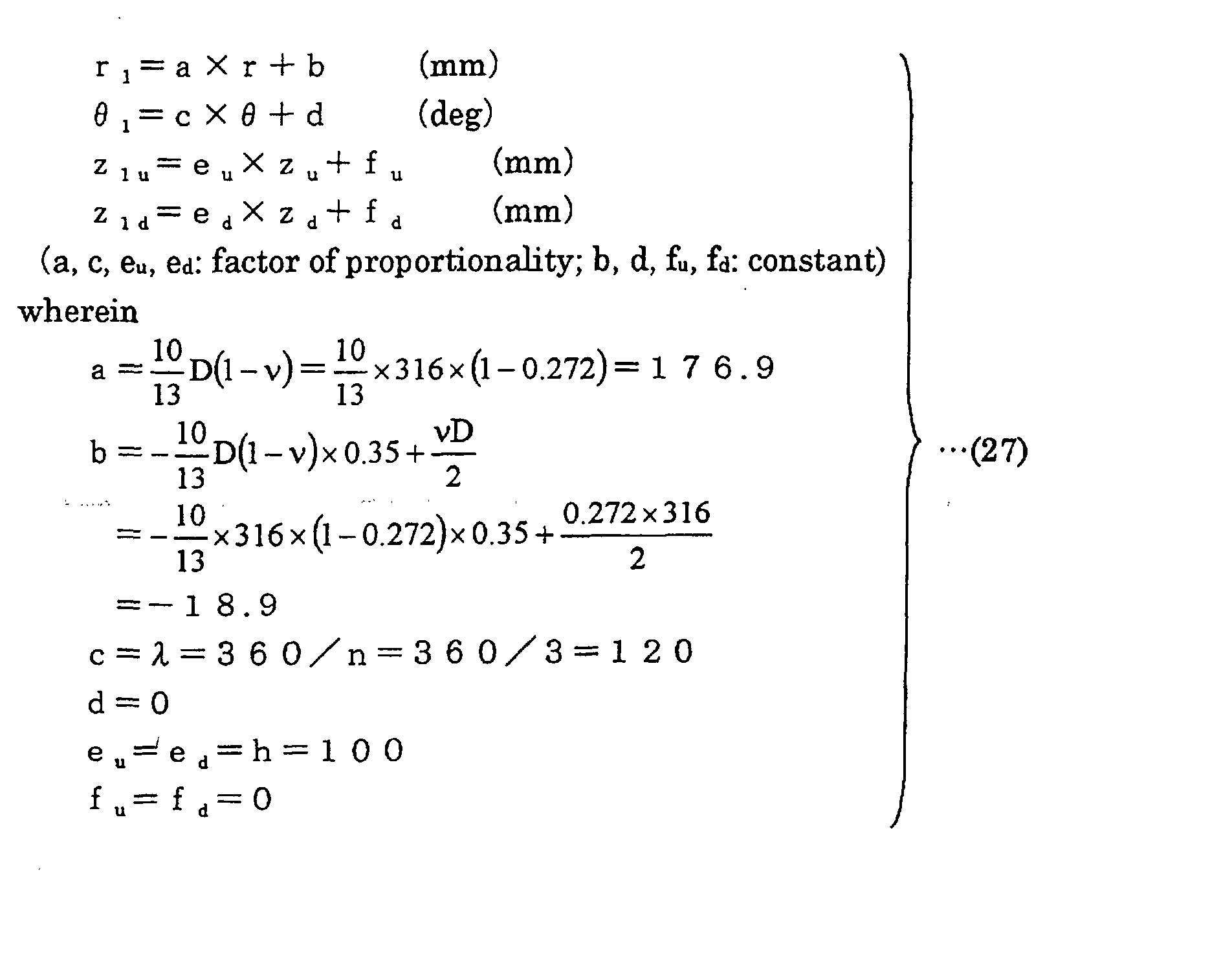
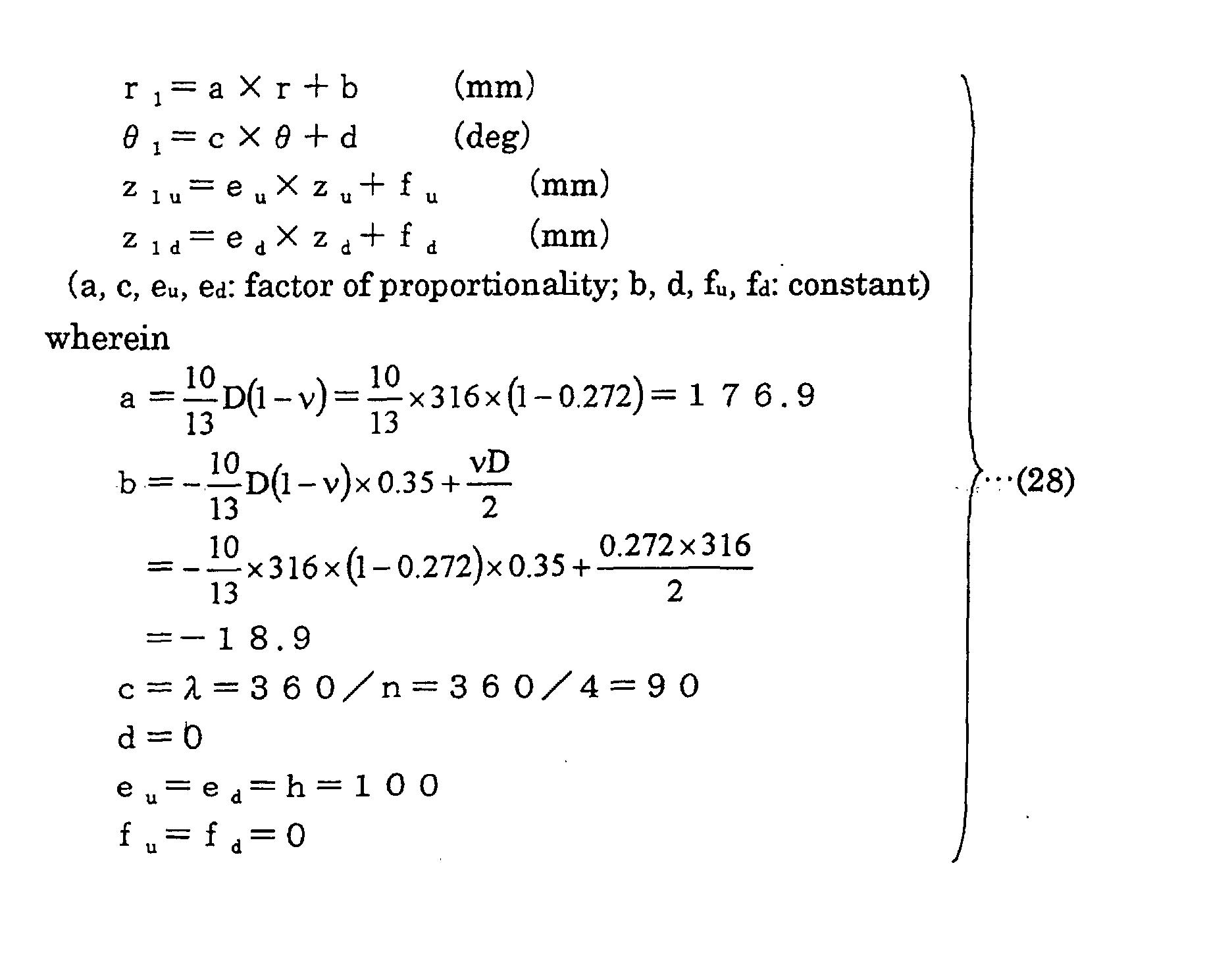
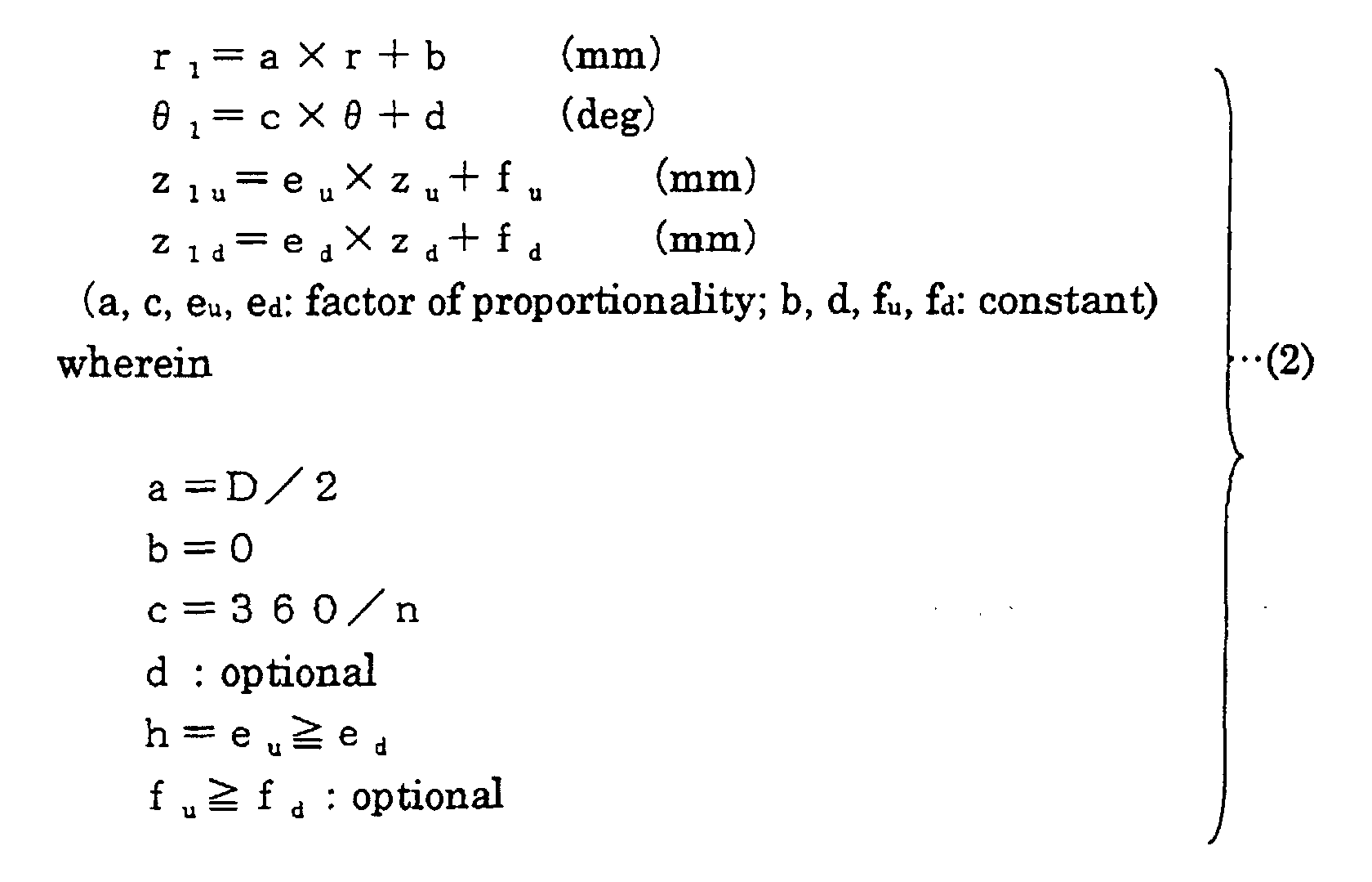
  • the height in the z direction which is the axial direction is h and the expansion angle of the blade is ⁇ ; r, ⁇ , z coordinates (r 1 , ⁇ 1 , z 1u ) that define the surface on the suction side of the blade and r, ⁇ , z coordinates (r 1 , ⁇ 1 , z 1d ) that define the surface on the blowing side of the blade are obtained by a transformation formula (7) below using three-dimensional coordinate values indicated in Tables 3 and 4. Then, the surface of the blade of the propeller fan is configured by a curved surface defined by the coordinates (r 1 , ⁇ 1 , z 1u ) and the coordinates (r 1 , ⁇ 1 , z 1d ).
  • the surface of a portion forming the surface of a blade of the propeller fan is configured by a curved surface defined by r, ⁇ , z coordinates (r 1 , ⁇ 1 , z 1u ) and r, ⁇ , z coordinates (r 1 , ⁇ 1 , z 1d ) obtained by the transformation formula (7) above.
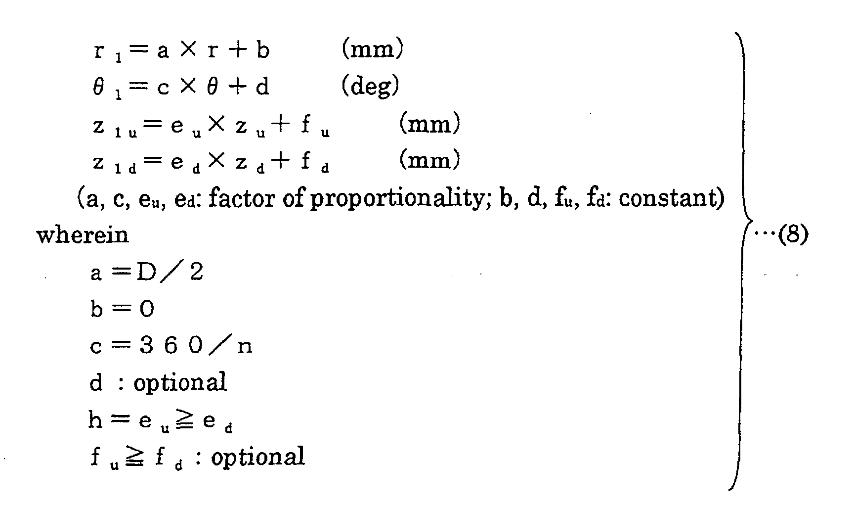
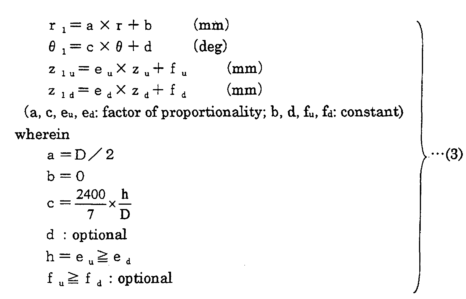
  • the height in the z direction which is the axial direction is h and the number of blades is n; r, ⁇ , z coordinates (r 1 , ⁇ 1 , z 1u ) that define the surface on the suction side of the blade and r, ⁇ , z coordinates (r 1 , ⁇ 1 , z 1d ) that define the surface on the blowing side of the blade are obtained by a transformation formula (8) below using three-dimensional coordinate values indicated in Tables 3 and 4. Then, the surface of the blade of the propeller fan is configured by a curved surface defined by the coordinates (r 1 , ⁇ 1 , z 1u ) and the coordinates (r 1 , ⁇ 1 , z 1d ).
  • the surface of a portion forming the surface of a blade of the propeller fan is configured by a curved surface defined by the coordinates (r 1 , ⁇ 1 , z 1u ) and the coordinates (r 1 , ⁇ 1 , z 1d ) obtained by the transformation formula (8) above.
  • r, ⁇ , z coordinates (r 1 , ⁇ 1 , z 1u ) that define the surface on the suction side of the blade and r, ⁇ , z coordinates (r 1 , ⁇ 1 , z 1d ) that define the surface on the blowing side of the blade are obtained by a transformation formula (9) below using three-dimensional coordinate values indicated in Tables 3 and 4. Then, the surface of the blade of the propeller fan is configured by a curved surface defined by the coordinates (r 1 , ⁇ 1 , z 1u ) and the coordinates (r 1 , ⁇ 1 z 1d ).
  • the surface of a portion forming the surface of a blade of the propeller fan is configured by a curved surface defined by the coordinates (r 1 , ⁇ 1 , z 1u ) and the coordinates (r 1 , ⁇ 1 , z 1d ) obtained by the transformation formula (9) above.
  • the boss ratio which is the ratio of the diameter of the propeller fan to that of a boss portion is ⁇
  • the height in the z direction which is the axial direction is h
  • the expansion angle of the blade is ⁇ ;
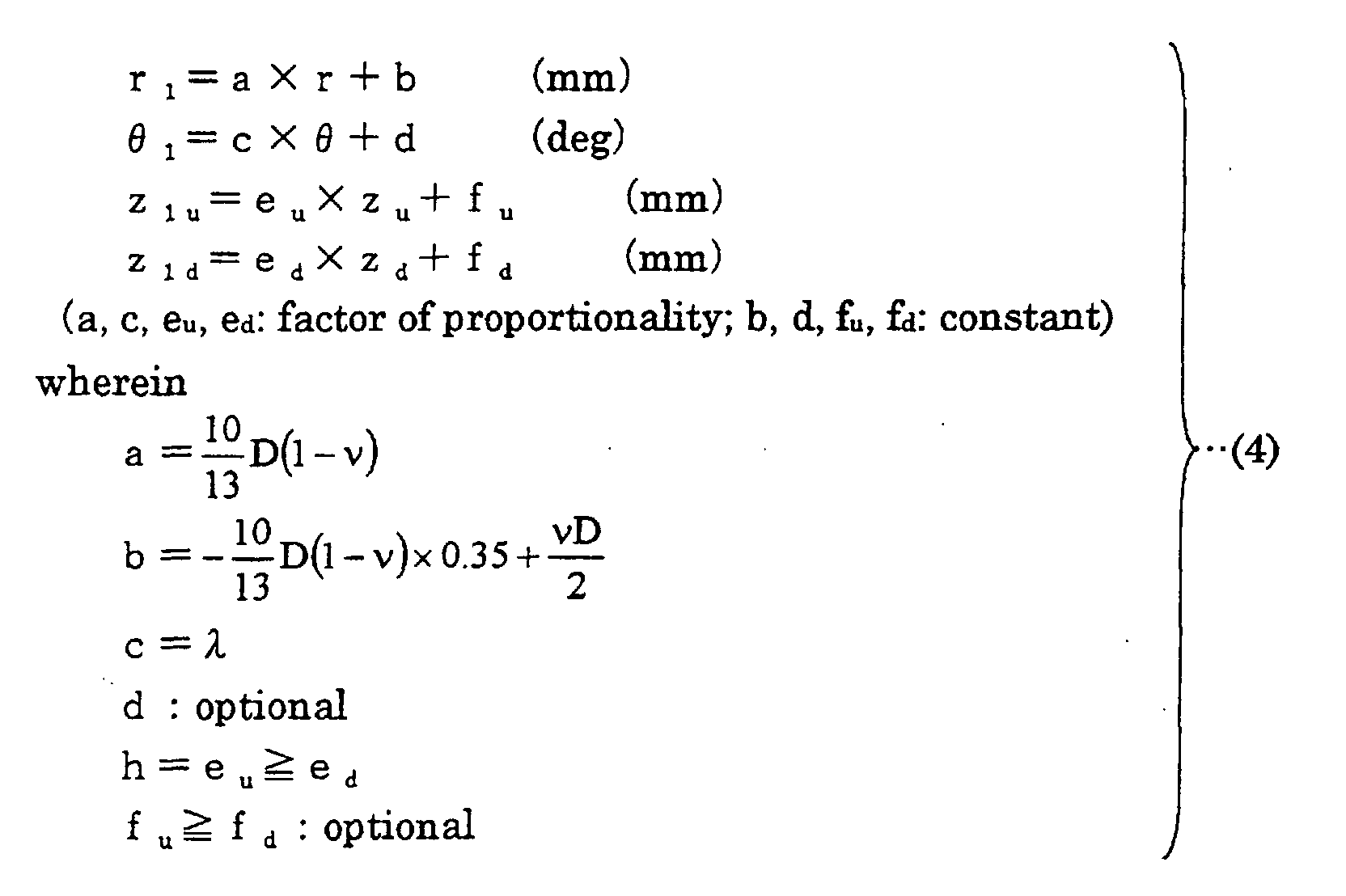
  • r, ⁇ , z coordinates (r 1 , ⁇ 1 , z 1u ) that define the surface on the suction side of the blade and r, ⁇ , z coordinates (r 1 , ⁇ 1 , z 1d ) that define the surface on the blowing side of the blade are obtained by a transformation formula (10) below using three-dimensional coordinate values indicated in Tables 3 and 4.
  • the surface of the blade of the propeller fan is configured by a curved surface defined by the coordinates (r 1 , ⁇ 1 , z 1u ) and the coordinates (r 1 , ⁇ 1 , z 1d ).
  • the surface of a portion forming the surface of a blade of the propeller fan is configured by a curved surface defined by the coordinates (r 1 , ⁇ 1 , z 1u ) and the coordinates (r 1 , ⁇ 1 , z 1d ) obtained by the transformation formula (10) above.
  • the boss ratio which is the ratio of the diameter of the propeller fan to that of the boss portion is ⁇
  • the height in the z direction which is the axial direction is h
  • the number of blades is n
  • r, ⁇ , z coordinates (r 1 , ⁇ 1 , z 1u ) that define the surface on the suction side of the blade and r, ⁇ , z coordinates (r 1 , ⁇ 1 , z 1d ) that define the surface on the blowing side of the blade are obtained by a transformation formula (11) below using three-dimensional coordinate values indicated in Tables 3 and 4.
  • the surface of the blade of the propeller fan is configured by a curved surface defined by the coordinates (r 1 , ⁇ 1 , z 1u ) and the coordinates (r 1 , ⁇ 1 , z 1d ).
  • the surface of a portion forming the surface of a blade of the propeller fan is configured by a curved surface defined by the coordinates (r 1 , ⁇ 1 , z 1u ) and the coordinates (r 1 , ⁇ 1 , z 1d ) obtained by the transformation formula (11) above.
  • the boss ratio which is the ratio of the diameter of the propeller fan to that of the boss portion is ⁇
  • the height in the z direction which is the axial direction is h
  • r, ⁇ , z coordinates (r 1 , ⁇ 1 , z 1u ) that define the surface on the suction side of the blade and r, ⁇ , z coordinates (r 1 , ⁇ 1 , z 1d ) that define the surface on the blowing side of the blade are obtained by a transformation formula (12) below using three-dimensional coordinate values indicated in Tables 3 and 4.
  • the surface of the blade of the propeller fan is configured by a curved surface defined by the coordinates (r 1 , ⁇ 1 , z 1u ) and the coordinates (r 1 , ⁇ 1 , z 1d ).
  • the surface of a portion forming the surface of a blade of the propeller fan is configured by a curved surface defined by the coordinates (r 1 , ⁇ 1 , z 1u ) and the coordinates (r 1 , ⁇ 1 , z 1d ) obtained by the transformation formula (12) above.
  • a fluid feeding device of the present invention includes a blower having any one of the propeller fans described above and a drive motor driving the propeller fan.
  • a curved shape defined by a r coordinate value, a ⁇ coordinate value and a z coordinate value indicated in Table 2 below is determined as a base shape of the surface of a blade of the propeller fan, and the surface of the blade of the propeller fan is configured by a curved surface obtained by enlarging or reducing the base shape in at lease one of r, ⁇ and z directions.
  • r indicates a non-dimensional r coordinate in the radial direction in the cylindrical coordinate system having the z axis as the rotation axis of the propeller fan
  • indicates a non-dimensional ⁇ coordinate in the circumferential direction in the cylindrical coordinate system having the z axis as the rotation axis of the propeller fan
  • z indicates a non-dimensional z coordinate in the axial direction (the direction of height) in the cylindrical coordinate system having the z axis as the rotation axis of the propeller fan.
  • each column (z u ) indicates a coordinate value on a negative pressure side (suction side) of the propeller fan
  • the bottom of each column (z d ) indicates a coordinate value on a positive pressure side (blowing side).
  • Table 102 indicates a non-dimensional coordinate value of z where r is within the range of 0.3 to 0.95 and ⁇ is within the range of 0.042 to 1. It is noted that the contents of Table 101 are the same as those in Table 102.
  • values within the range of ⁇ 5% of coordinate values calculated by a transformation formula of the present invention should be interpreted as included in a range of error and equivalent to the coordinate values of the present invention.
  • shape defined by the coordinate values within the range of ⁇ 5% of the coordinate values calculated by a transformation formula of the present invention should be interpreted as included in a technical range of the present invention.
  • the surface of a portion forming the surface of a blade of the propeller fan is configured by a curved surface obtained by enlarging or reducing the base shape in at least one of r, ⁇ and z directions.
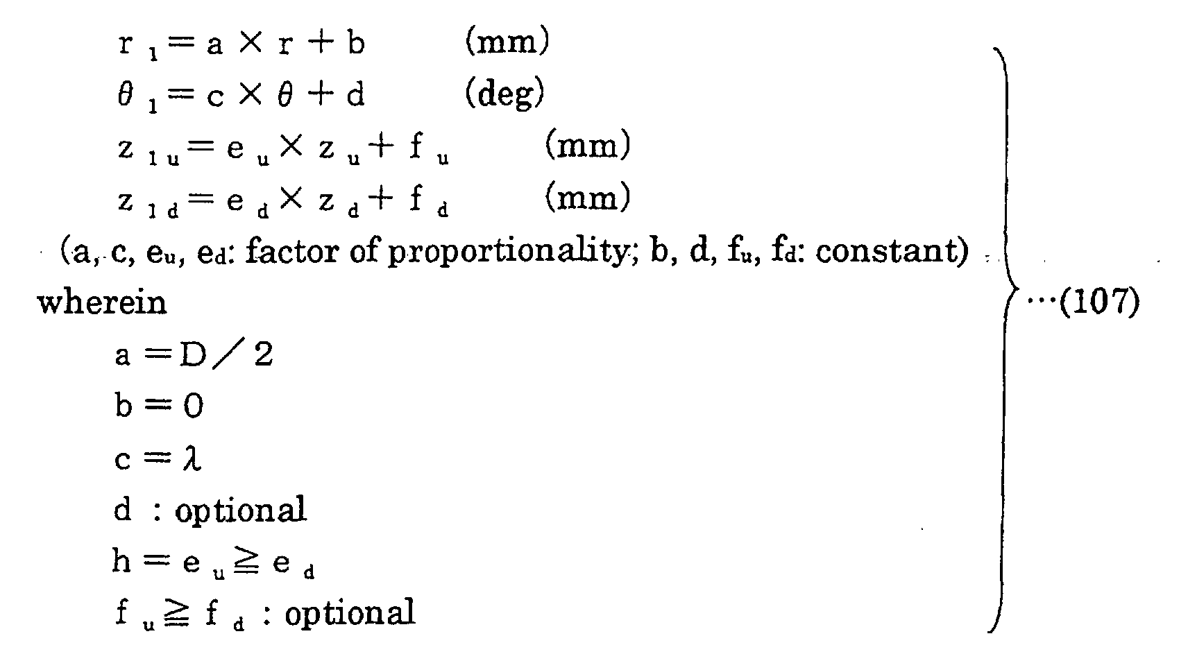
  • the height in the z direction which is the axial direction is h and the expansion angle of the blade is ⁇ ; r, ⁇ , z coordinates (r 1 , ⁇ 1 , z 1u ) that define the surface on the suction side of the blade and r, ⁇ , z coordinates (r 1 , ⁇ 1 , z 1d ) that define the surface on the blowing side of the blade are obtained by a transformation formula (107) below using three-dimensional coordinate values indicated in Table 2. Then, the surface of the blade of the propeller fan is configured by a curved surface defined by the coordinates (r 1 , ⁇ 1 , z 1u ) and the coordinates (r 1 , ⁇ 1 , z 1d ).
  • the surface of a portion forming the surface of a blade of the propeller fan is configured by a curved surface defined by the coordinates (r 1 , ⁇ 1 , z 1u ) and the coordinates (r 1 , ⁇ 1 , z 1d ) obtained by the transformation formula (107) above.
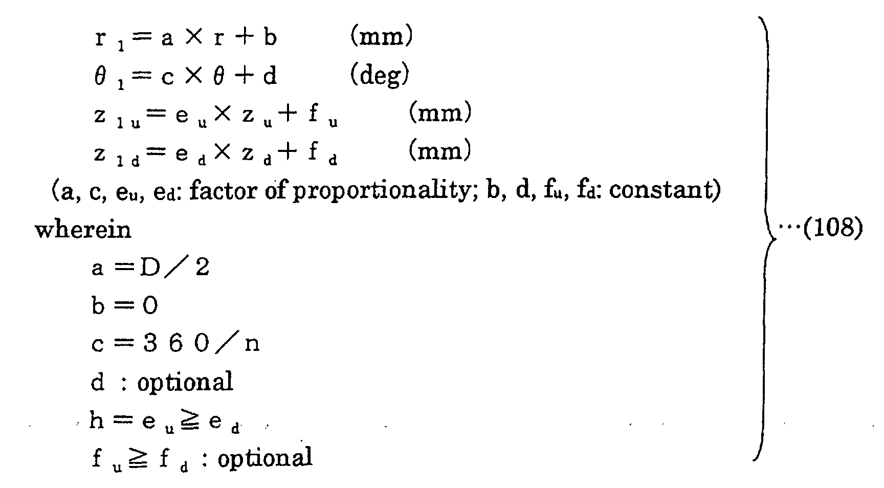
  • r, ⁇ , z coordinates (r 1 , ⁇ 1 , z 1u ) that define the surface on the suction side of the blade and r, ⁇ , z coordinates (r 1 , ⁇ 1 , z 1d ) that define the surface on the blowing side of the blade are obtained by a transformation formula (108) below using three-dimensional coordinate values indicated in Table 2. Then, the surface of the blade of the propeller fan is configured by a curved surface defined by the coordinates (r 1 , ⁇ 1 , z 1u ) and the coordinates (r 1 , ⁇ 1 , z 1d ).
  • the surface of a portion forming the surface of a blade of the propeller fan is configured by a curved surface defined by the coordinates (r 1 , ⁇ 1 , z 1u ) and the coordinates (r 1 , ⁇ 1 , z 1d ) obtained by the transformation formula (108) above.
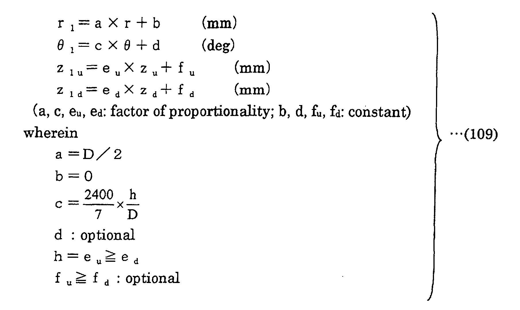
  • r, ⁇ , z coordinates (r 1 , ⁇ 1 , z 1u ) that define the surface on the suction side of the blade and r, ⁇ , z coordinates (r 1 , ⁇ 1 , z 1d ) that define the surface on the blowing side of the blade are obtained by a transformation formula (109) below using three-dimensional coordinate values indicated in Table 2. Then, the surface of the blade of the propeller fan is configured by a curved surface defined by the coordinates (r 1 , ⁇ 1 , z 1u ) and the coordinates (r 1 , ⁇ 1 , z 1d ).
  • the surface of a portion forming the surface of a blade of the propeller fan is configured by a curved surface defined by the coordinates (r 1 , ⁇ 1 , z 1u ) and the coordinates (r 1 , ⁇ 1 , z 1d ) obtained by the transformation formula (109) above.
  • the boss ratio which is the ratio of the diameter of the propeller fan to that of a boss portion is ⁇
  • the height in the z direction which is the axial direction is h
  • the expansion angle of the blade is ⁇
  • r, ⁇ , z coordinates (r 1 , ⁇ 1 , z 1u ) that define the surface on the suction side of the blade and r, ⁇ , z coordinates (r 1 , ⁇ 1 , z 1d ) that define the surface on the blowing side of the blade are obtained by a transformation formula (110) below using three-dimensional coordinate values indicated in Table 2.
  • the surface of the blade of the propeller fan is configured by a curved surface defined by the coordinates (r 1 , ⁇ 1 , z 1u ) and the coordinates (r 1 , ⁇ 1 , z 1d ).
  • the surface of a portion forming the surface of a blade of the propeller fan is configured by a curved surface defined by the coordinates (r 1 , ⁇ 1 , z 1u ) and the coordinates (r 1 , ⁇ 1 , z 1d ) obtained by the transformation formula (110) above.
  • the boss ratio which is the ratio of the diameter of the propeller fan to that of a boss portion is ⁇
  • the height in the z direction which is the axial direction is h
  • the number of blades is n
  • r, ⁇ , z coordinates (r 1 , ⁇ 1 , z 1u ) that define the surface on the suction side of the blade and r, ⁇ , z coordinates (r 1 , ⁇ 1 , z 1d ) that define the surface on the blowing side of the blade are obtained by a transformation formula (111) below using three-dimensional coordinate values indicated in Table 2.
  • the surface of the blade of the propeller fan is configured by a curved surface defined by the coordinates (r 1 , ⁇ 1 , z 1u ) and the coordinates (r 1 , ⁇ 1 , z 1d ).
  • the surface of a portion forming the surface of a blade of the propeller fan is configured by a curved surface defined by the coordinates (r 1 , ⁇ 1 , z 1u ) and the coordinates (r 1 , ⁇ 1 , z 1d ) obtained by the transformation formula (111) above.
  • the boss ratio which is the ratio of the diameter of the propeller fan to that of a boss portion is ⁇
  • the height in the z direction which is the axial direction is h
  • r, ⁇ , z coordinates (r 1 , ⁇ 1 , z 1u ) that define the surface on the suction side of the blade and r, ⁇ , z coordinates (r 1 , ⁇ 1 , z 1d ) that define the surface on the blowing side of the blade are obtained by a transformation formula (112) below using three-dimensional coordinate values indicated in Table 102.
  • the surface of the blade of the propeller fan is configured by a curved surface defined by the coordinates (r 1 , ⁇ 1 , z 1u ) and the coordinates (r 1 , ⁇ 1 , z 1d ).
  • the surface of a portion forming the surface of a blade of the propeller fan is configured by a curved surface defined by the coordinates (r 1 , ⁇ 1 , z 1u ) and the coordinates (r 1 , ⁇ 1 , z 1d ) obtained by the transformation formula (112) above.
  • a fluid feeding device of the present invention includes a blower having any one of the propeller fans described above and a drive motor driving the propeller fan.
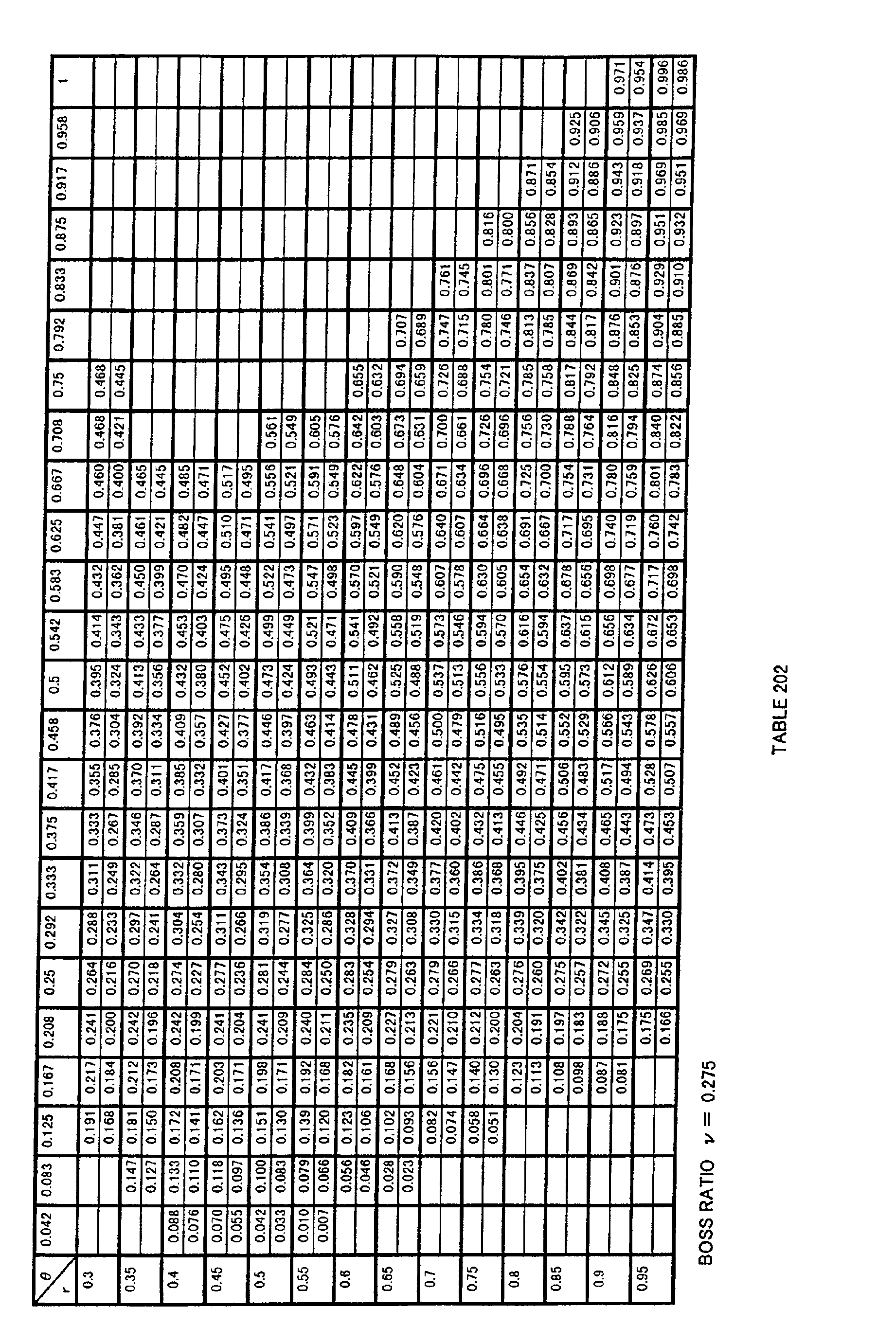
  • a propeller fan when coordinates in a cylindrical coordinate system having a z axis as a rotation axis of the propeller fan are (r, ⁇ , z), the shape of a curved surface defined by a r coordinate value, a ⁇ coordinate value and a z coordinate value indicated in Table 202 below is determined as a base shape of the surface of a blade of the propeller fan, and the surface of the blade of the propeller fan is configured by a curved surface obtained by enlarging or reducing the base shape in at least one of r, ⁇ and z directions.
  • r indicates a non-dimensional r coordinate in the radial direction in the cylindrical coordinate system having the z axis as the rotation axis of the propeller fan
  • indicates a non-dimensional ⁇ coordinate in the circumferential direction in the cylindrical coordinate system having the z axis as the rotation axis of the propeller fan
  • z indicates a non-dimensional z coordinate in the axial direction (the direction of height) in the cylindrical coordinate system having the z axis as the rotation axis of the propeller fan.
  • each column (z u ) indicates a coordinate value on a negative pressure side (suction side) of the propeller fan
  • the bottom of each column (z d ) indicates a coordinate value on a positive pressure side (blowing side) thereof.
  • Table 202 indicates a non-dimensional coordinate value of z where r is within the range of 0.3 to 0.95 and where ⁇ is within the range of 0.042 to 1. It is noted that the contents of Table 201 are the same as those in Table 202.
  • values within the range of ⁇ 5% of coordinate values calculated by a transformation formula of the present invention should be interpreted as included in a range of error and equivalent to the coordinate values of the present invention.
  • shape defined by the coordinate values within the range of ⁇ 5% of coordinate values calculated by a transformation formula of the present invention should be interpreted as included in a technical range of the present invention.
  • the surface of a portion forming the surface of a blade of the propeller fan is configured by a curved surface obtained by enlarging or reducing the base shape in at least one of r, ⁇ and z directions.
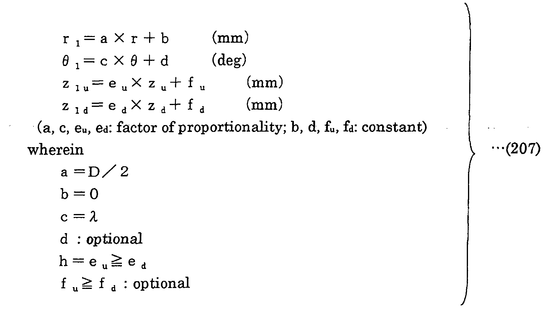
  • the height in the z direction which is the axial direction is h and the expansion angle of the blade is ⁇ ; r, ⁇ , z coordinates (r 1 , ⁇ 1 , z 1u ) that define the surface on the suction side of the blade and r, ⁇ , z coordinates (r 1 , ⁇ 1 , z 1d ) that define the surface on the blowing side of the blade are obtained by a transformation formula (207) below using three-dimensional coordinate values indicated in Table 2. Then, the surface of the blade of the propeller fan is configured by a curved surface defined by the coordinates (r 1 , ⁇ 1 , z 1u ) and the coordinates (r 1 , ⁇ 1 , z 1d ).
  • the surface of a portion forming the surface of a blade of the propeller fan is configured by a curved surface defined by the coordinates (r 1 , ⁇ 1 , z 1u ) and the coordinates (r 1 , ⁇ 1 , z 1d ) obtained by the transformation formula (207) above.
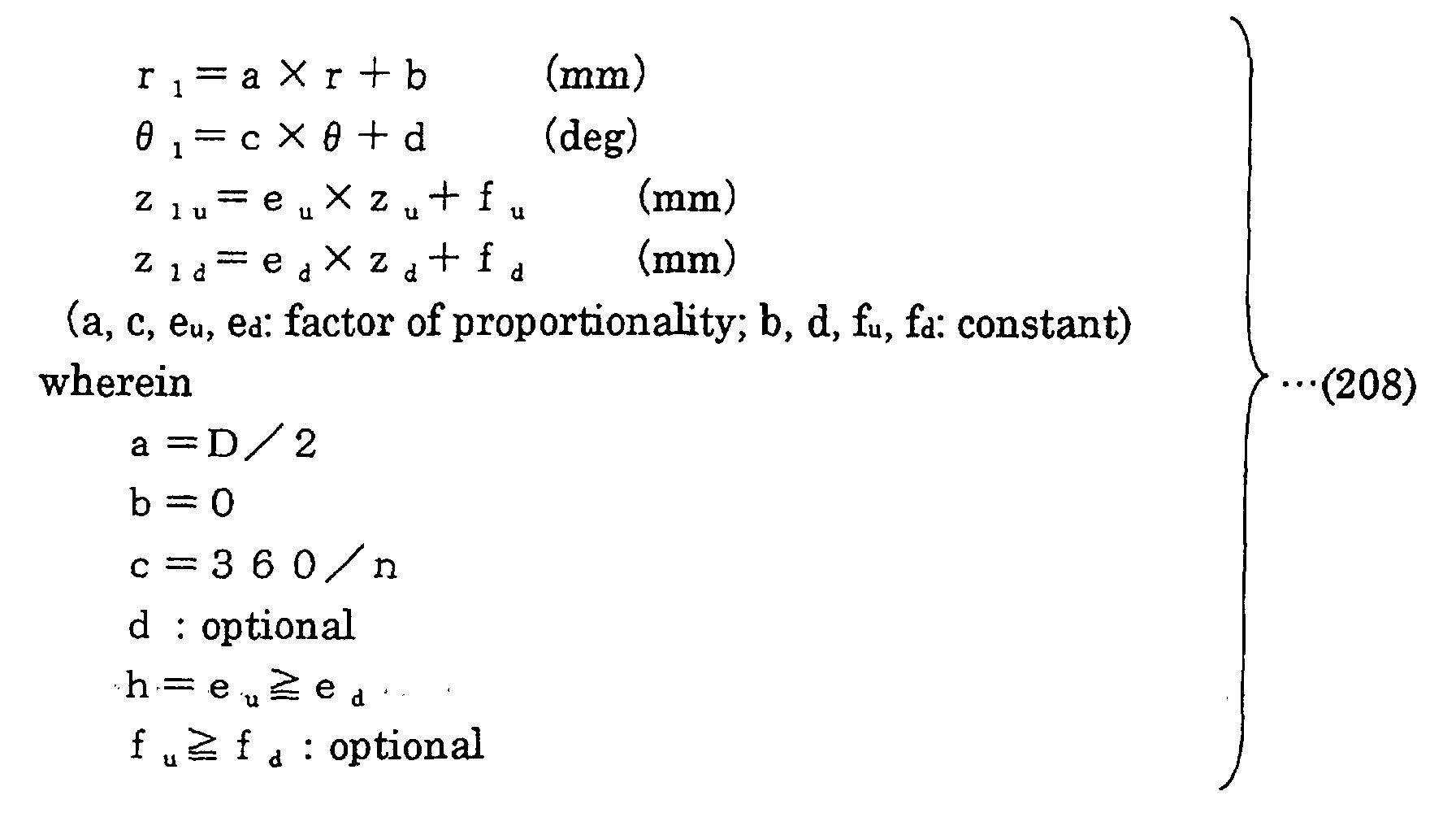
  • r, ⁇ , z coordinates (r 1 , ⁇ 1 , z 1u ) that define the surface on the suction side of the blade and r, ⁇ , z coordinates (r 1 , ⁇ 1 , z 1d ) that define the surface on the blowing side of the blade are obtained by a transformation formula (208) below using three-dimensional coordinate values indicated in Table 2. Then, the surface of the blade of the propeller fan is configured by a curved surface defined by the coordinates (r 1 , ⁇ 1 , z 1u ) and the coordinates (r 1 , ⁇ 1 , z 1d ).
  • the surface of a portion forming the surface of a blade of the propeller fan is configured by a curved surface defined by the coordinates (r 1 , ⁇ 1 , z 1u ) and the coordinates (r 1 , ⁇ 1 , z 1d ) obtained by the transformation formula (208) above.
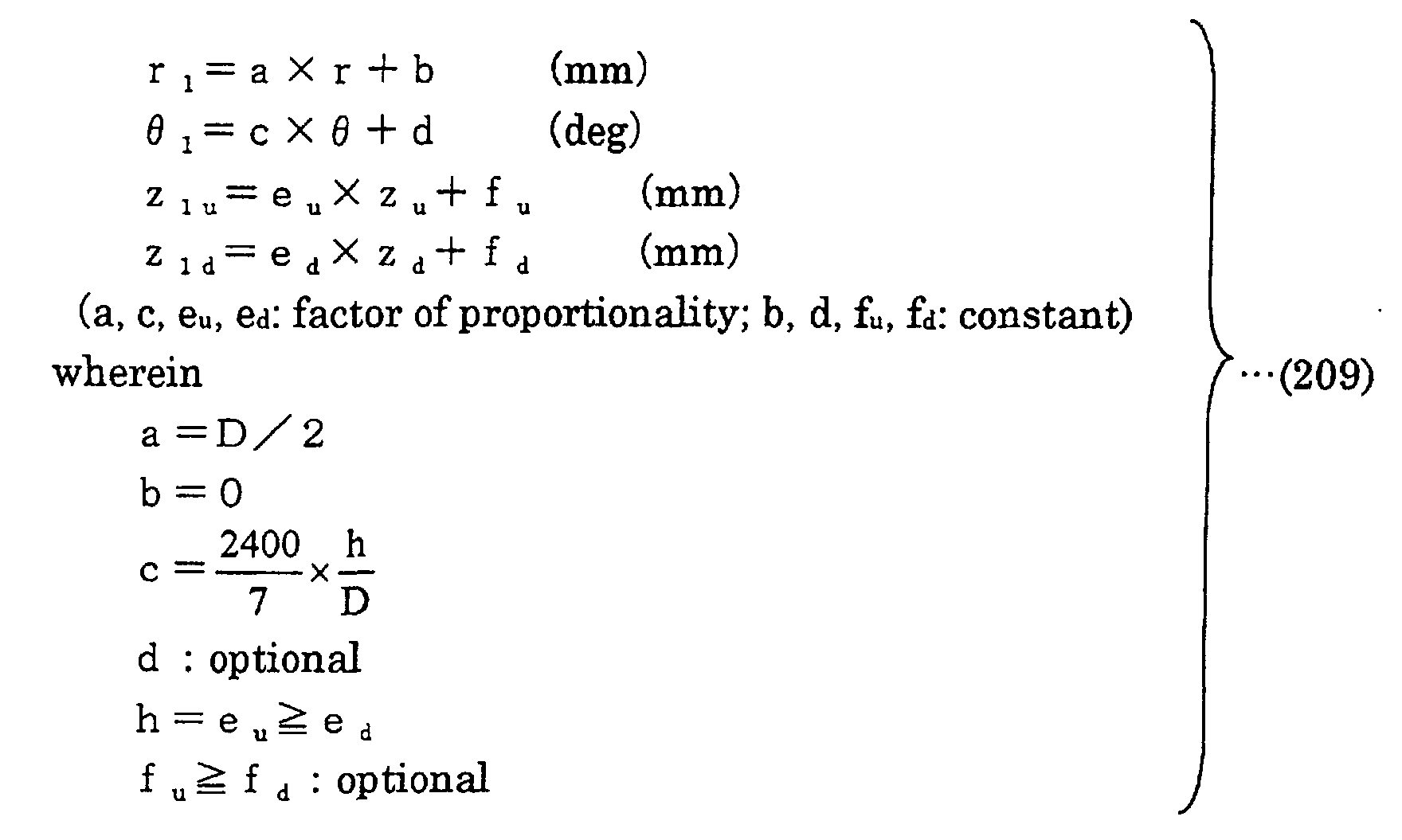
  • r, ⁇ , z coordinates (r 1 , ⁇ 1 , z 1u ) that define the surface on the suction side of the blade and r, ⁇ , z coordinates (r 1 , ⁇ 1 , z 1d ) that define the surface on the blowing side of the blade are obtained by a transformation formula (209) below using three-dimensional coordinate values indicated in Table 202 above. Then, the surface of the blade of the propeller fan is configured by a curved surface defined by the coordinates (r 1 , ⁇ 1 , z 1u ) and the coordinates (r 1 , ⁇ 1 , z 1d ).
  • the surface of a portion forming the surface of a blade of the propeller fan is configured by a curved surface defined by the coordinates (r 1 , ⁇ 1 , z 1u ) and the coordinates (r 1 , ⁇ 1 , z 1d ) obtained by the transformation formula (209) above.
  • the boss ratio which is the ratio of the diameter of the propeller fan to that of a boss portion is ⁇
  • the height in the z direction which is the axial direction is h
  • the expansion angle of the blade is ⁇ ;
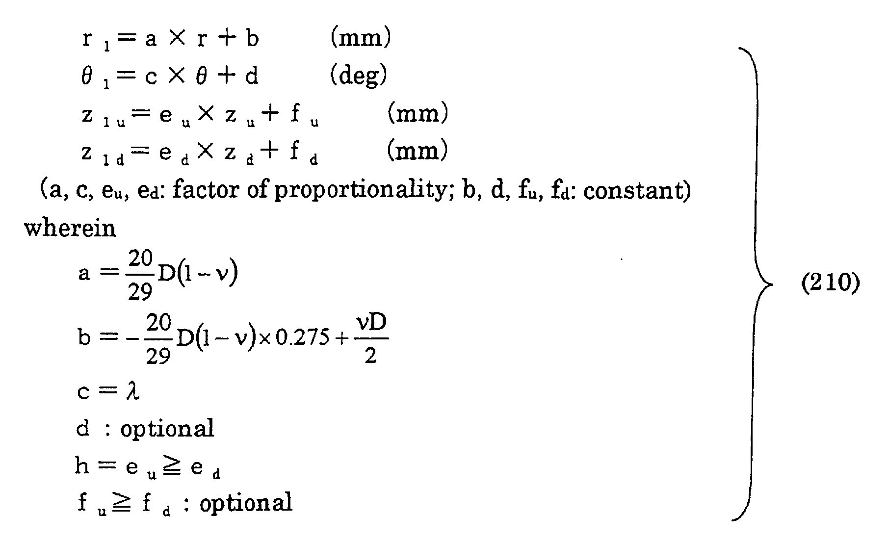
  • r, ⁇ , z coordinates (r 1 , ⁇ 1 , z 1u ) that define the surface on the suction side of the blade and r, ⁇ , z coordinates (r 1 , ⁇ 1 , z 1d ) that define the surface on the blowing side of the blade are obtained by a transformation formula (210) below using three-dimensional coordinate values indicated in Table 202.
  • the surface of the blade of the propeller fan is configured by a curved surface defined by the coordinates (r 1 , ⁇ 1 , z 1u ) and the coordinates (r 1 , ⁇ 1 , z 1d ).
  • the surface of a portion forming the surface of a blade of the propeller fan is configured by a curved surface defined by the coordinates (r 1 , ⁇ 1 , z 1u ) and the coordinates (r 1 , ⁇ 1 , z 1d ) obtained by the transformation formula (210) above.
  • the boss ratio which is the ratio of the diameter of the propeller fan to that of a boss portion is ⁇
  • the height in the z direction which is the axial direction is h
  • the number of blades is n
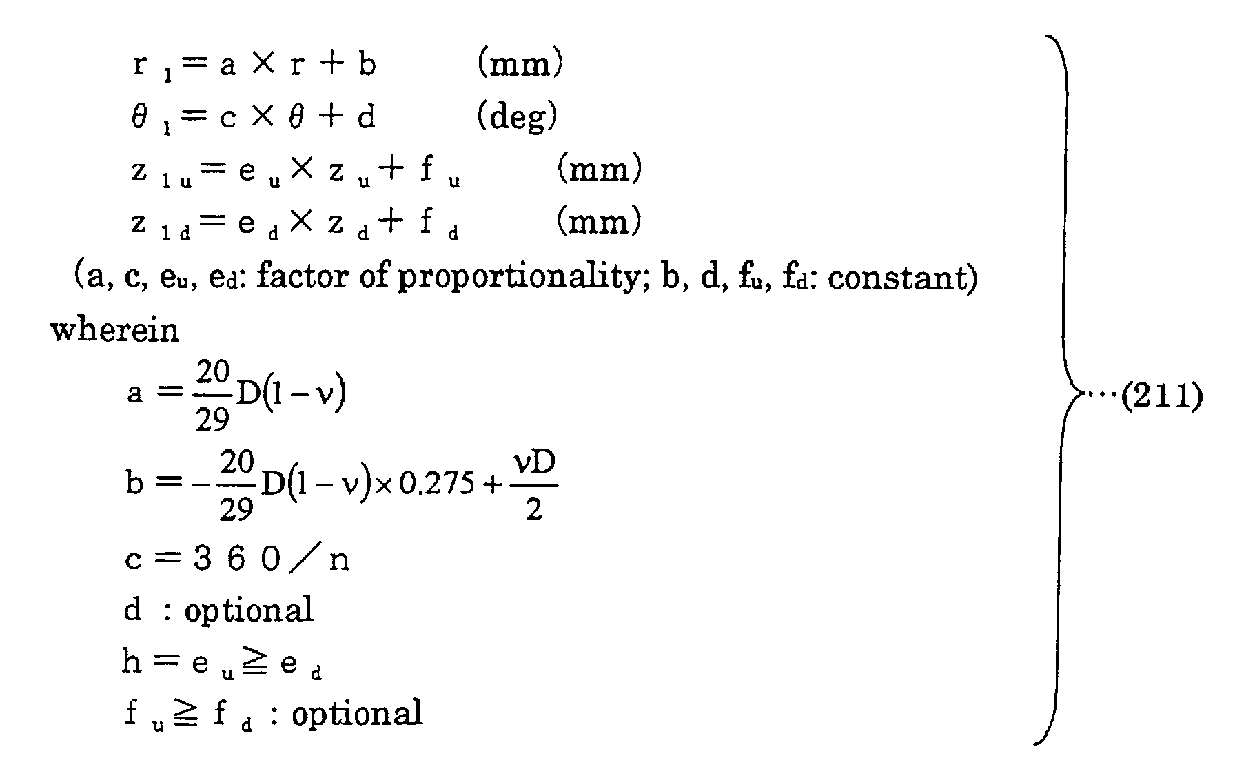
  • r, ⁇ , z coordinates (r 1 , ⁇ 1 , z 1u ) that define the surface on the suction side of the blade and r, ⁇ , z coordinates (r 1 , ⁇ 1 , z 1d ) that define the surface on the blowing side of the blade are obtained by a transformation formula (211) below using three-dimensional coordinate values indicated in Table 202.
  • the surface of the blade of the propeller fan is configured by a curved surface defined by the coordinates (r 1 , ⁇ 1 , z 1u ) and the coordinates (r 1 , ⁇ 1 , z 1d ).
  • the surface of a portion forming the surface of a blade of the propeller fan is configured by a curved surface defined by the coordinates (r 1 , ⁇ 1 , z 1u ) and the coordinates (r 1 , ⁇ 1 , z 1d ) obtained by the transformation formula (211) above.
  • the boss ratio which is the ratio of the diameter of the propeller fan to that of a boss portion is ⁇
  • the height in the z direction which is the axial direction of the propeller fan is h
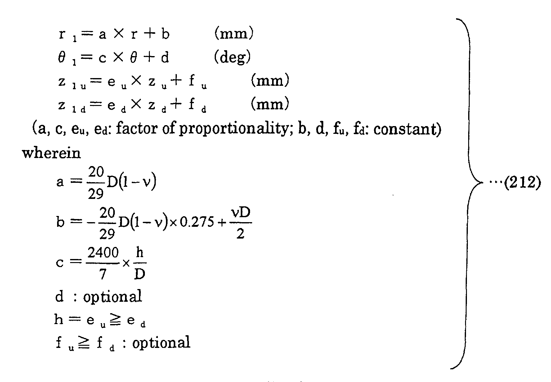
  • r, ⁇ , z coordinates (r 1 , ⁇ 1 , z 1u ) that define the surface on the suction side of the blade and r, ⁇ , z coordinates (r 1 , ⁇ 1 , z 1d ) that define the surface on the blowing side of the blade are obtained by a transformation formula (212) below using three-dimensional coordinate values indicated in Table 2.
  • the surface of the blade of the propeller fan is configured by a curved surface defined by the coordinates (r 1 , ⁇ 1 , z 1u ) and the coordinates (r 1 , ⁇ 1 , z 1d ).
  • the surface of a portion forming the surface of a blade of the propeller fan is configured by a curved surface defined by the coordinates (r 1 , ⁇ 1 , z 1u ) and the coordinates (r 1 , ⁇ 1 , z 1d ) obtained by the transformation formula (212) above.
  • a fluid feeding device of the present invention includes a blower having any one of the propeller fans described above and a drive motor driving the propeller fan.
  • Embodiments of a propeller fan, a die for molding the propeller fan, and a fluid feeding device according to the present invention will be described below with reference to Figs. 1 to 30.
  • Fig. 1 shows a front view of a propeller fan 1 of the present invention.
  • Propeller fan 1 of the present invention is molded in one piece by synthetic resin such as, for example, AS resin with glass fiber.
  • the diameter D 400 mm
  • the height in the axial direction (z direction) h 140 mm
  • the number of blades n 3
  • three blades 3 are radially and integrally provided on the periphery of a boss portion 2.
  • the shape of the surface of blade 3 of propeller fan 1 is obtained based on a base shape defined by specific coordinate values.
  • the shape of a curved surface defined by coordinate values obtained by transforming the coordinate values in the base shape in the r, ⁇ and z directions using prescribed transformation formulas respectively is determined as the shape of the surface of blade 3 of propeller fan 1.
  • the base shape of the present invention is typically defined by the coordinate values indicated in Tables 3 and 4 described earlier.
  • the shape which is defined by coordinate values obtained by uniformly transforming the coordinate values indicated in Tables 3 and 4 described earlier by e.g. multiplying the coordinate values with prescribed coefficients, should also be interpreted as equivalent to the base shape of the present invention.
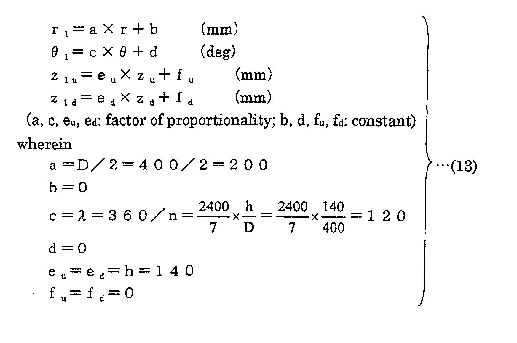
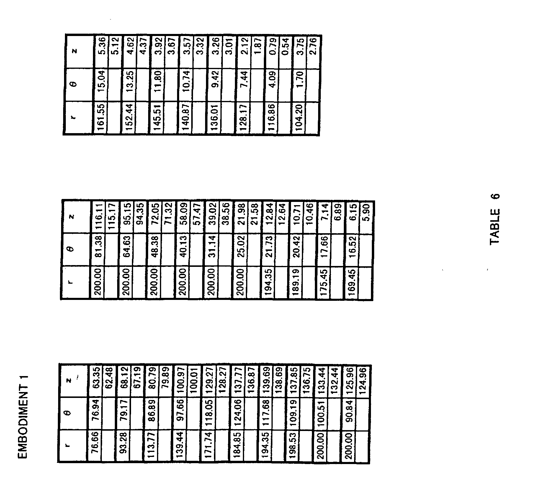
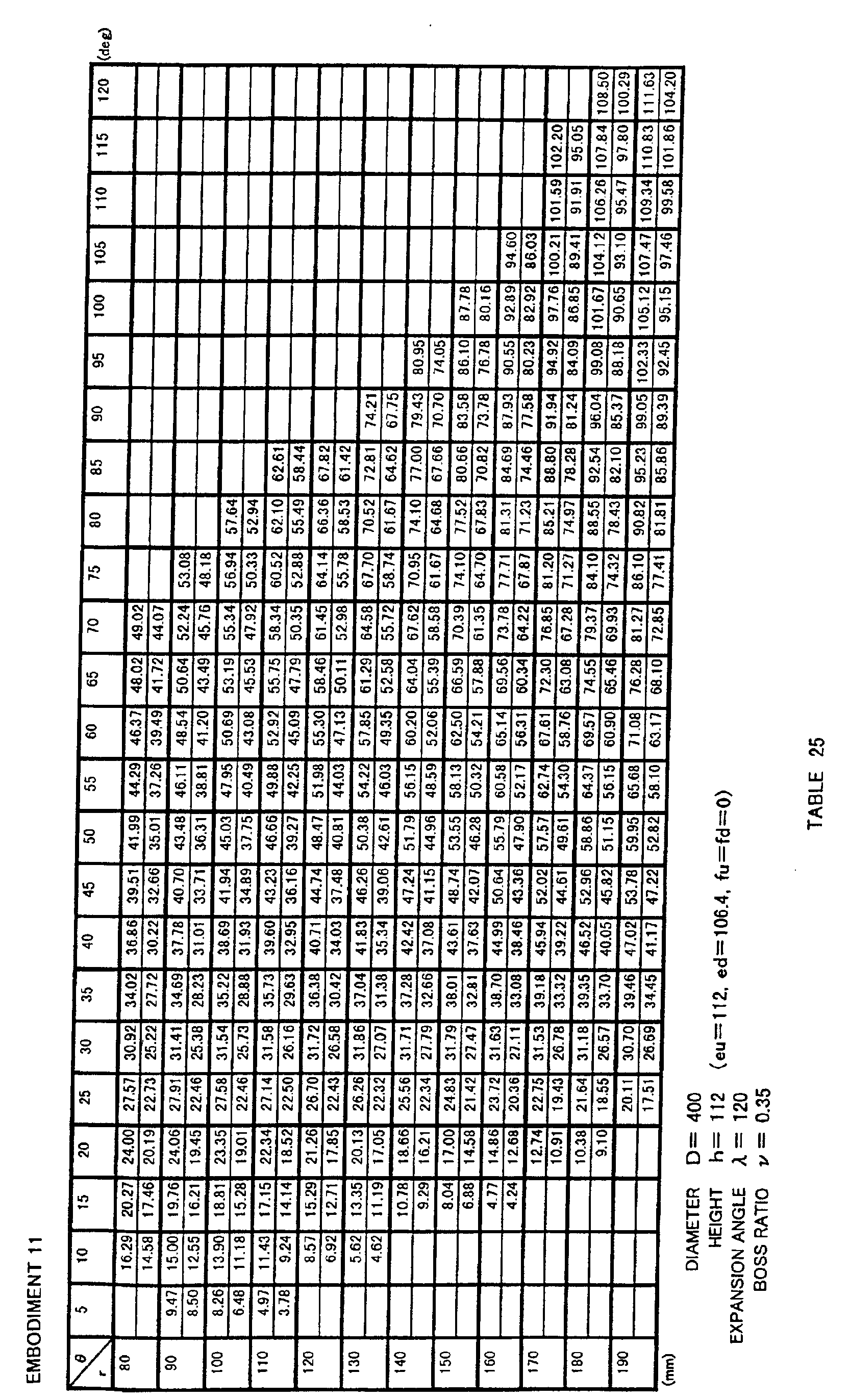
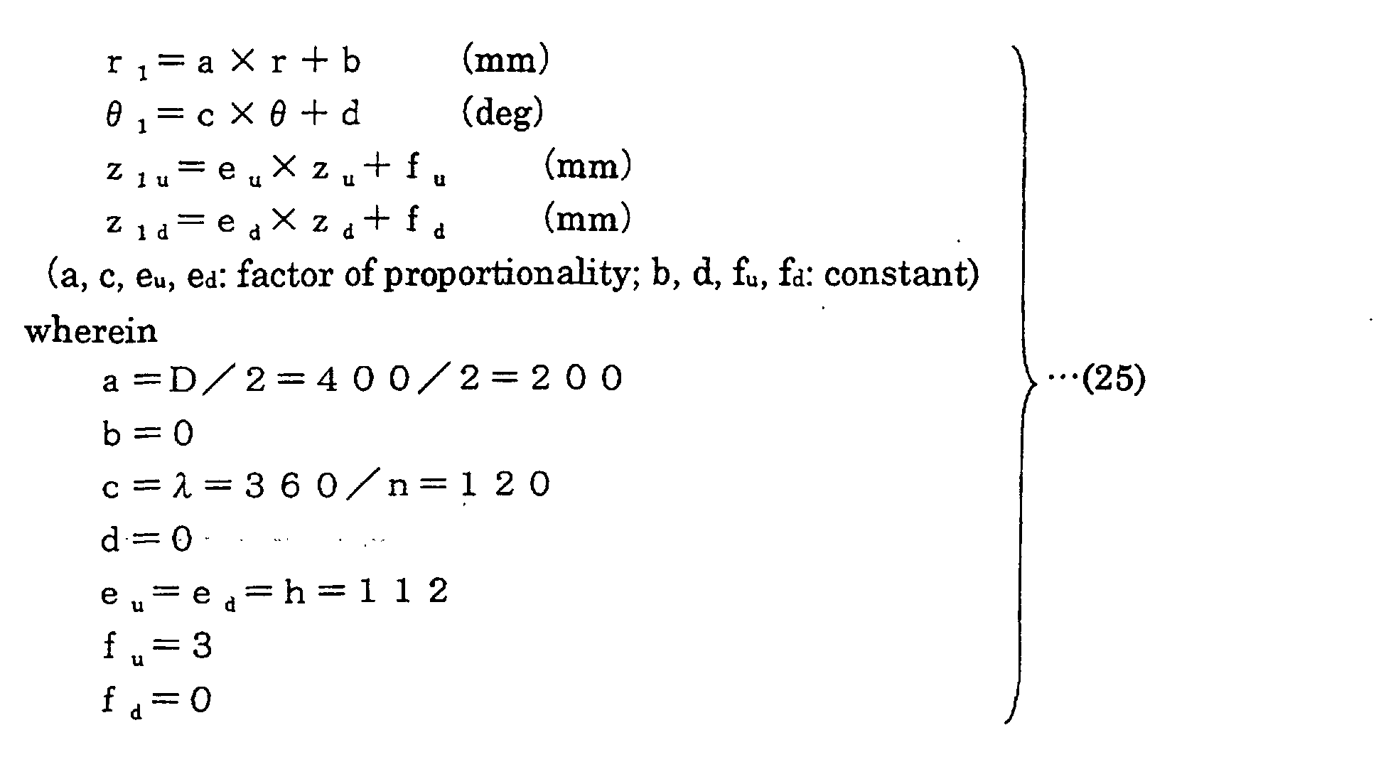
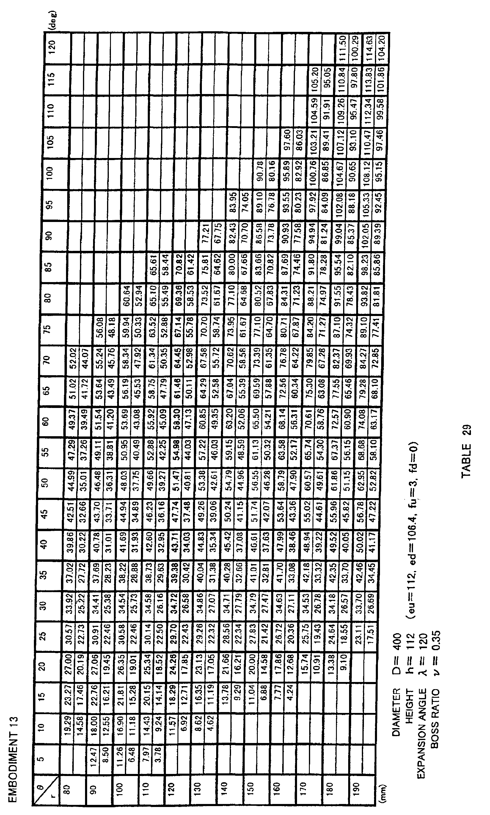
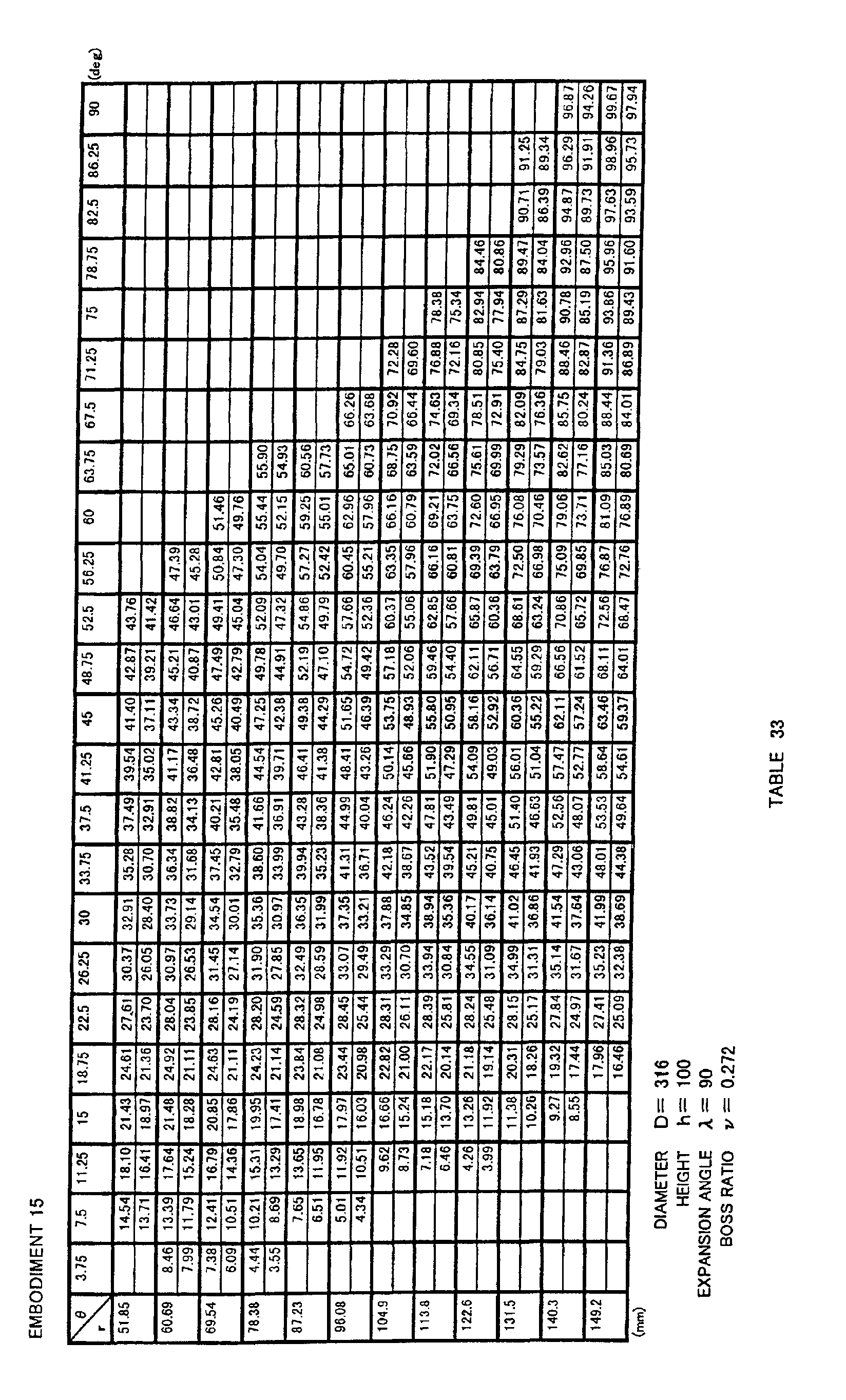
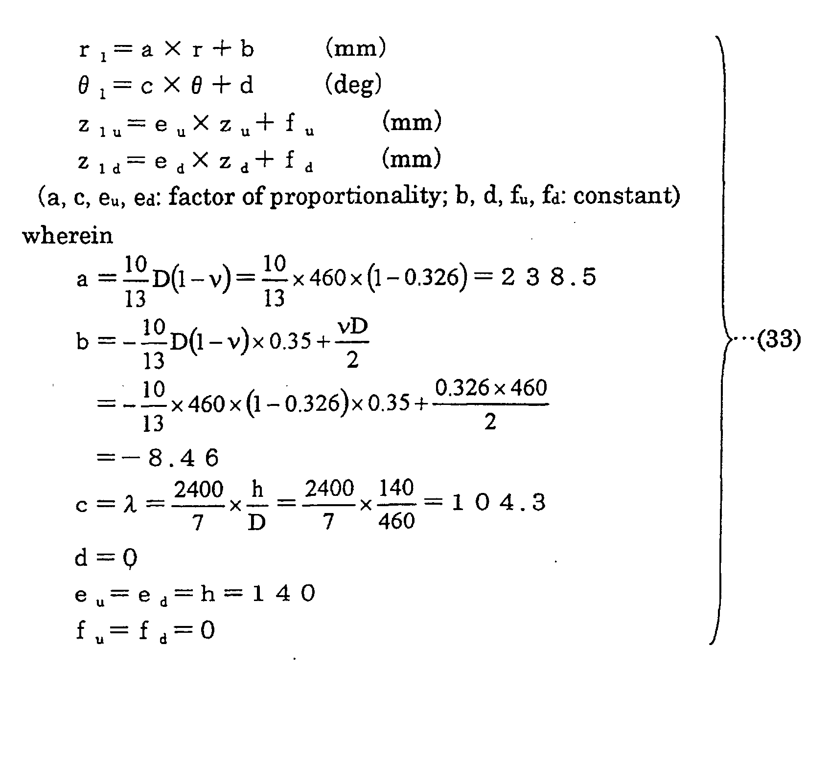
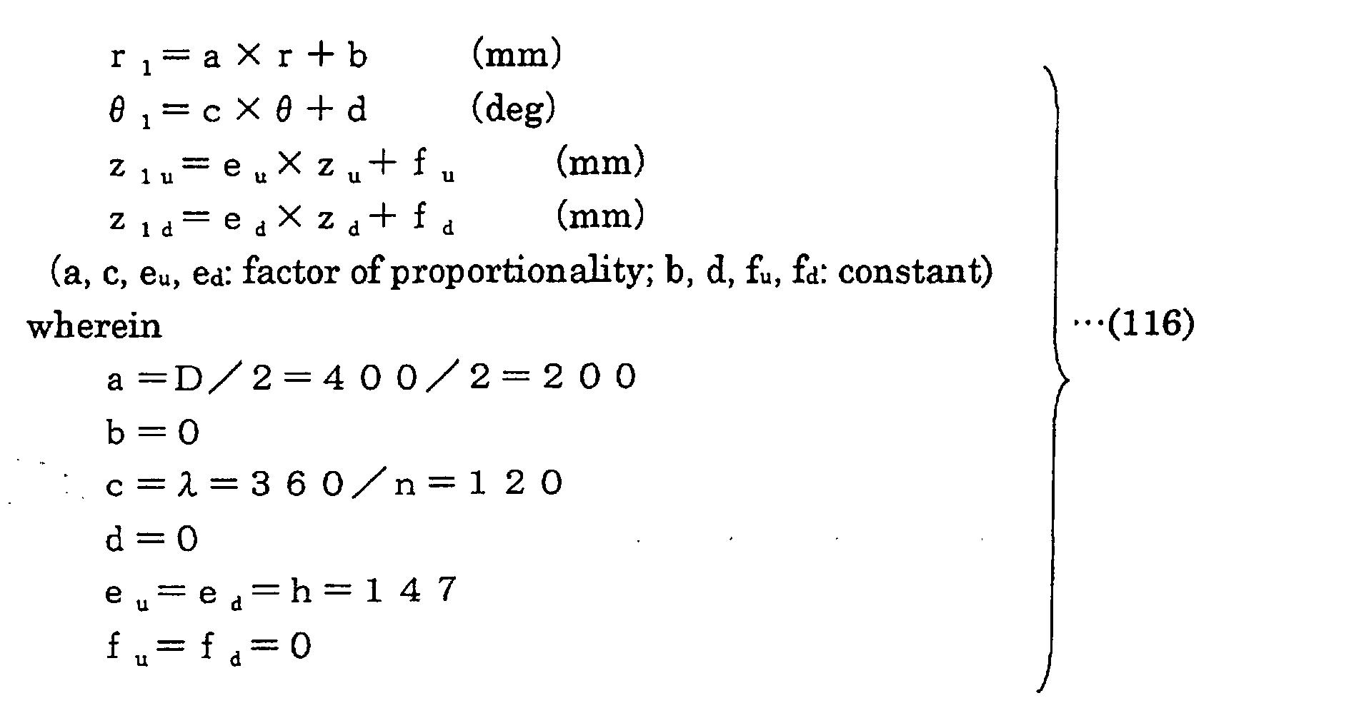
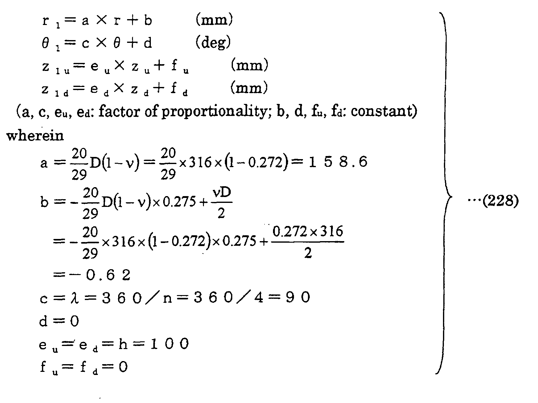
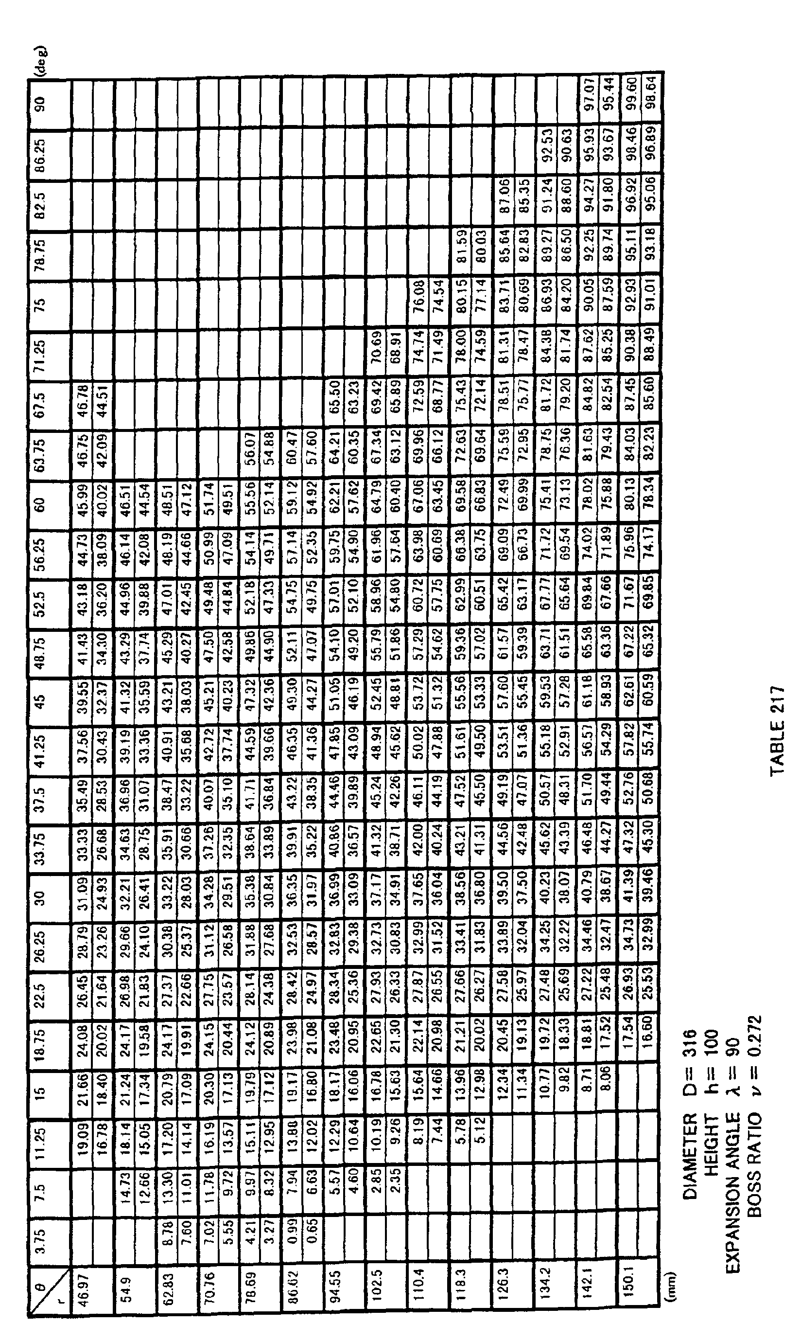
  • coordinates (r 1 , ⁇ 1 , z 1u ) of a surface on a negative pressure side of blade 3 and coordinates (r 1 , ⁇ 1 , z 1d ) of a surface on a positive pressure side of blade 3 are coordinate values obtained by transforming non-dimensionally expressed three-dimensional coordinate values indicated in Tables 3 and 4 using a transformation formula 13, and the surface on the negative pressure side and the surface on the positive pressure side are configured by curved surfaces defined by the obtained coordinate values, i.e. a curved surface specified by coordinate values indicated in Tables 5 and 6.
  • the curved surface may also be specified by coordinate values within the range of ⁇ 5 % of each coordinate value.
  • Fig. 1 shows a cylindrical coordinate system of r and ⁇ by dashed lines. It is noted that, though the z axis is not shown in Fig. 1, the z axis is a line passing the center of rotation 0 of boss portion 2 of propeller fan 1 in Fig. 1 and perpendicular to the plane of the drawing (that is, a line overlapping with a core of the rotation axis of propeller fan 1).
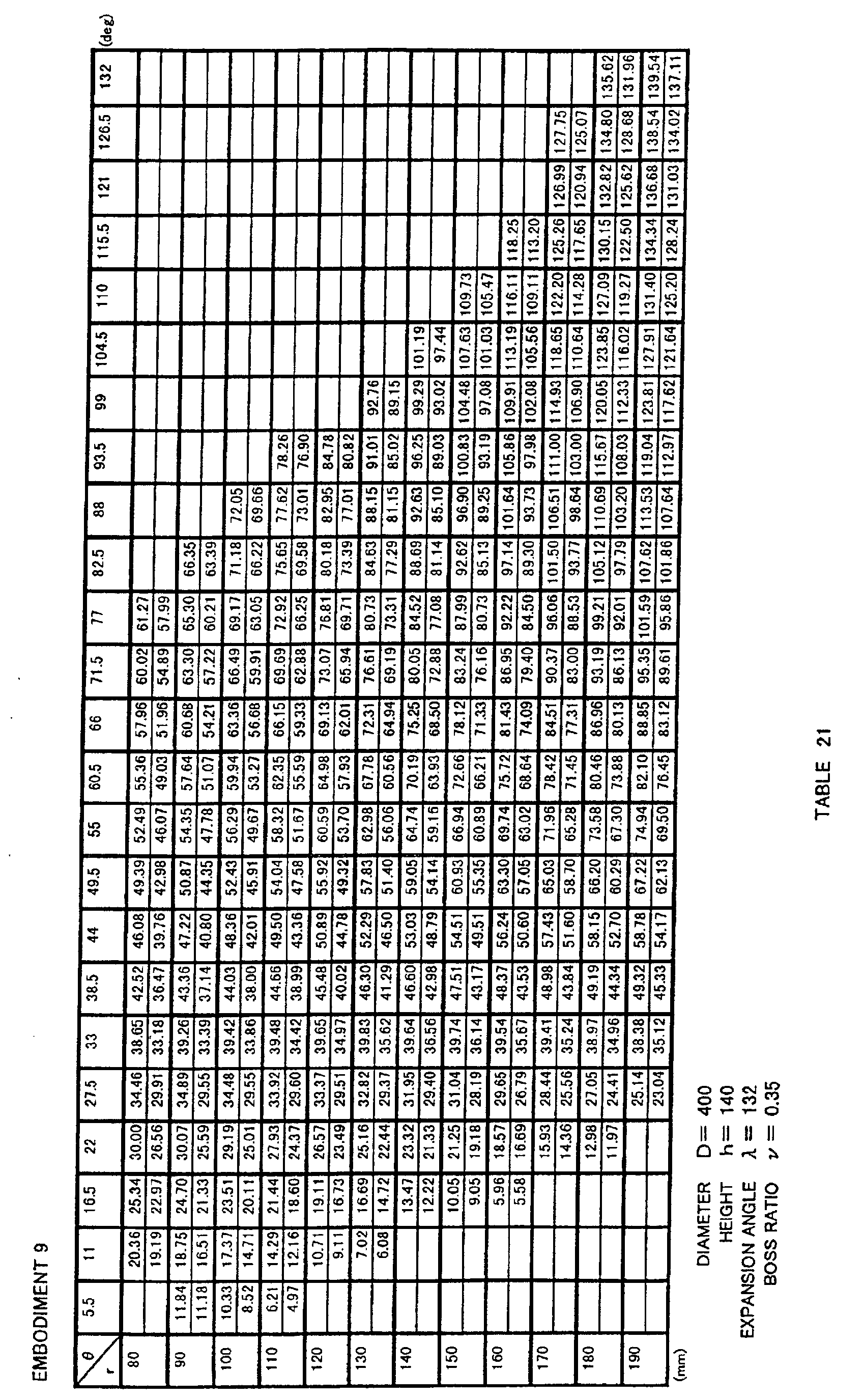
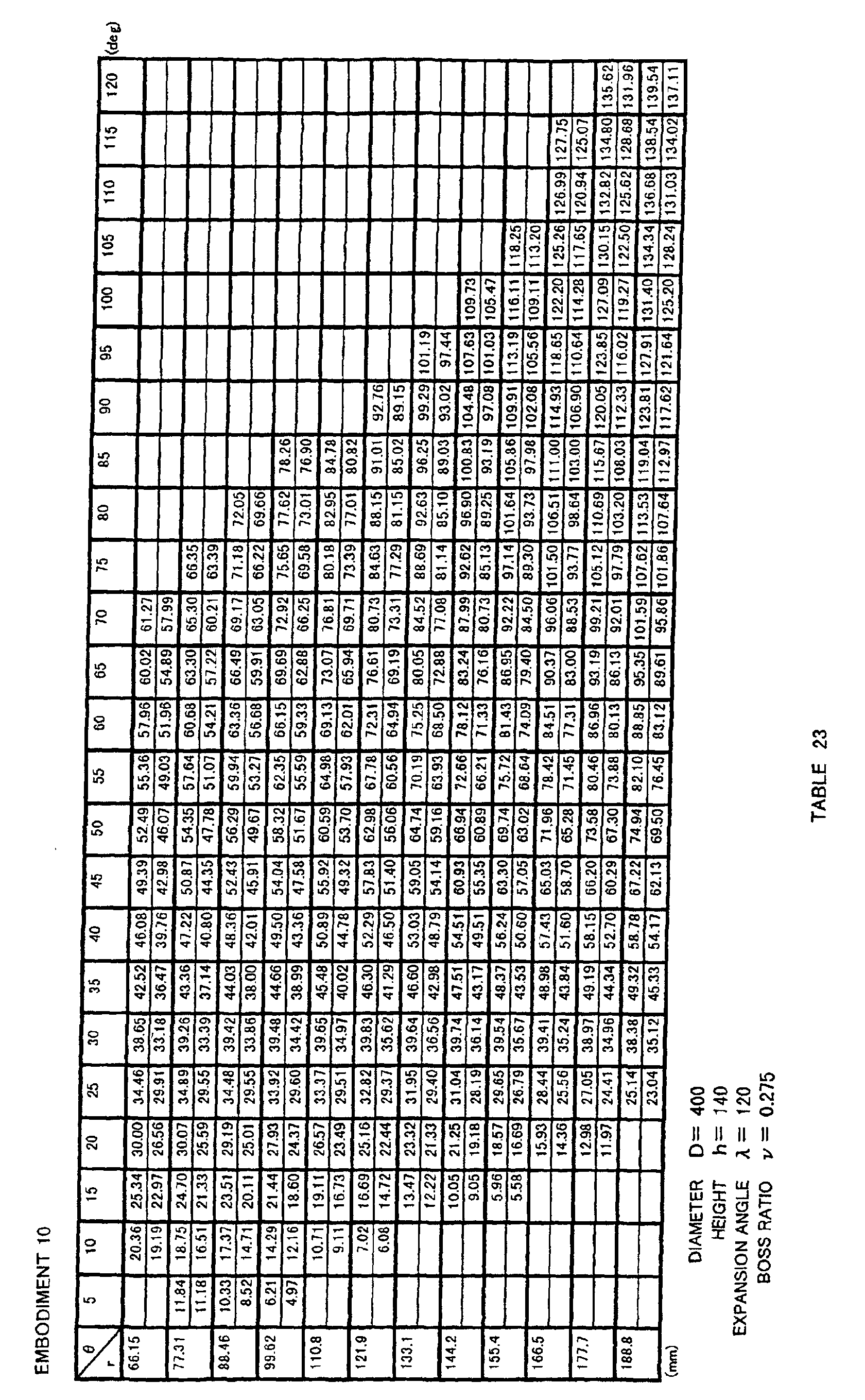
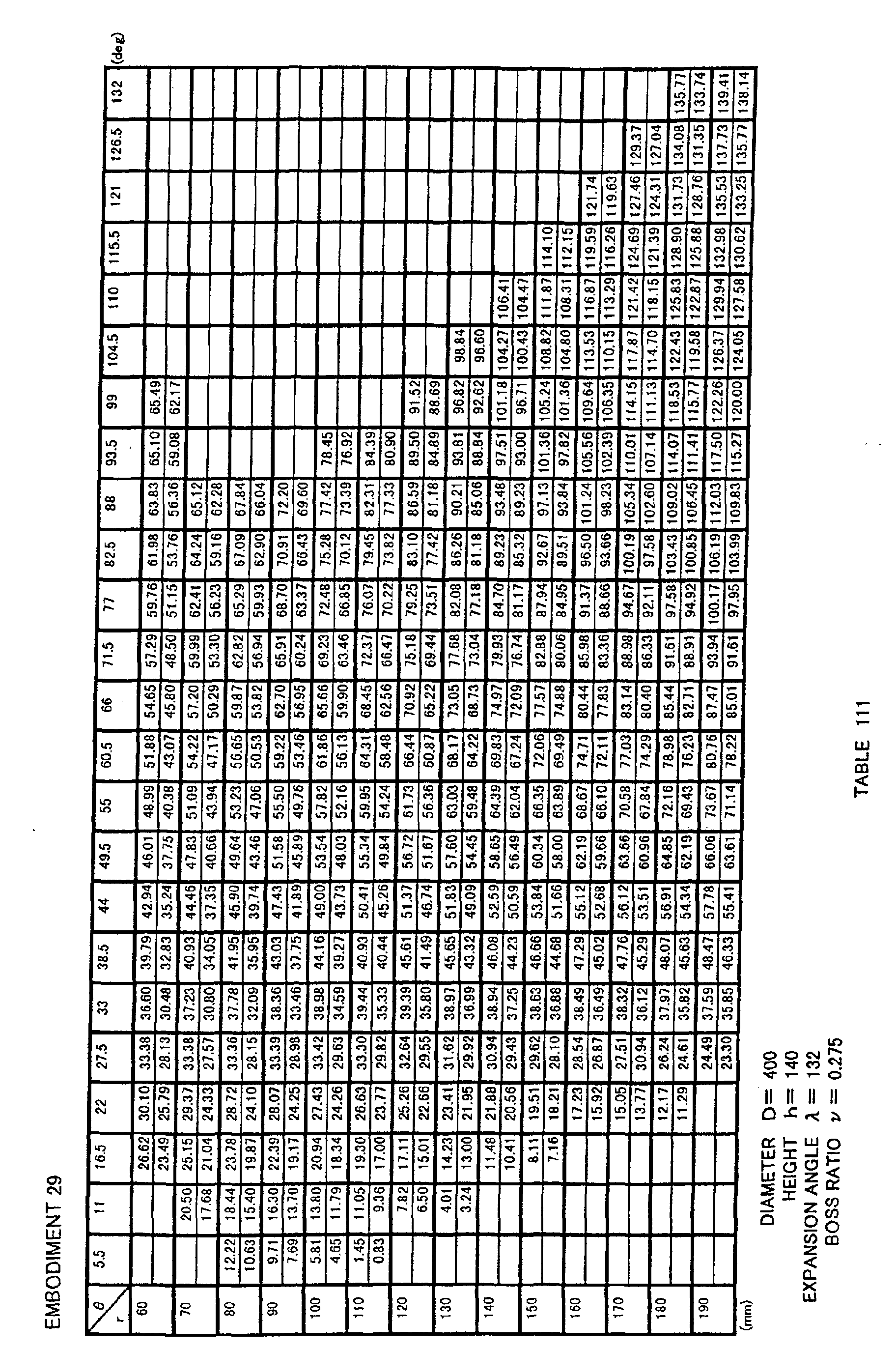
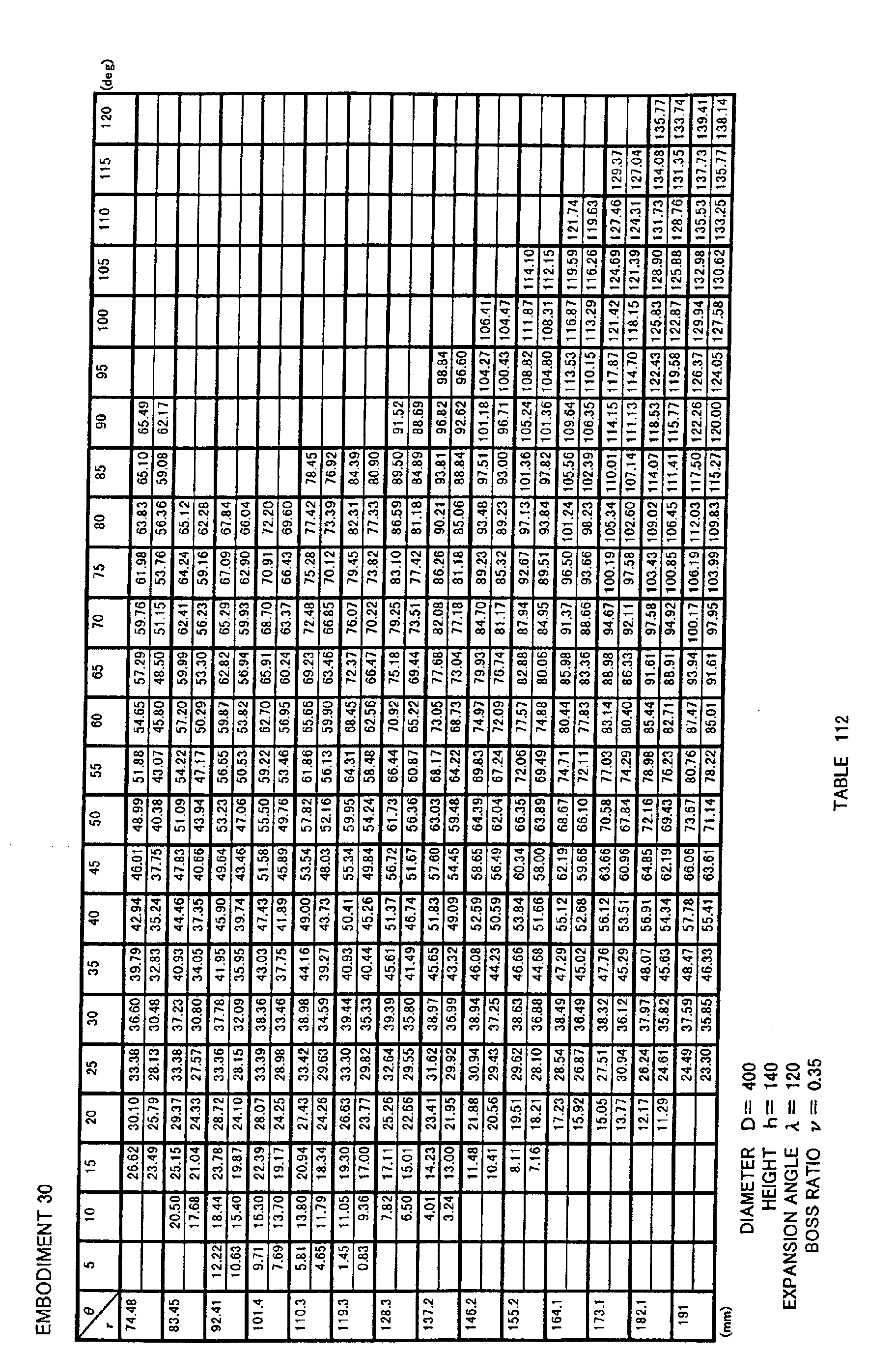
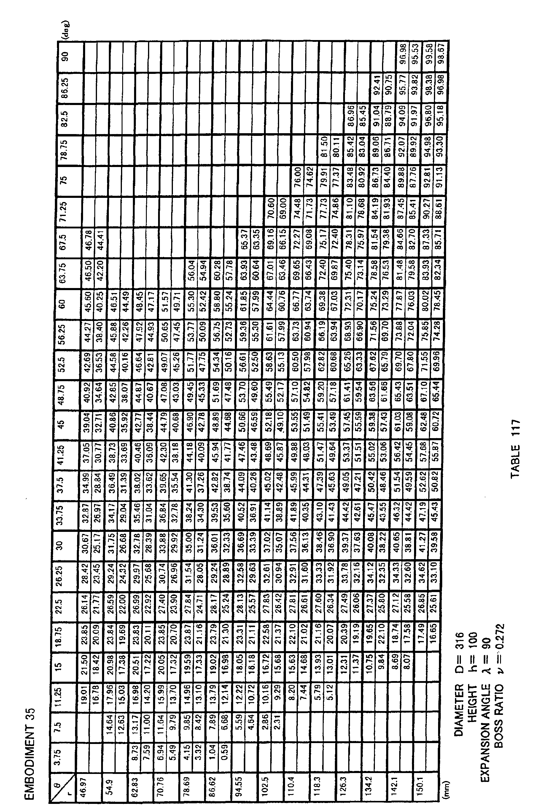
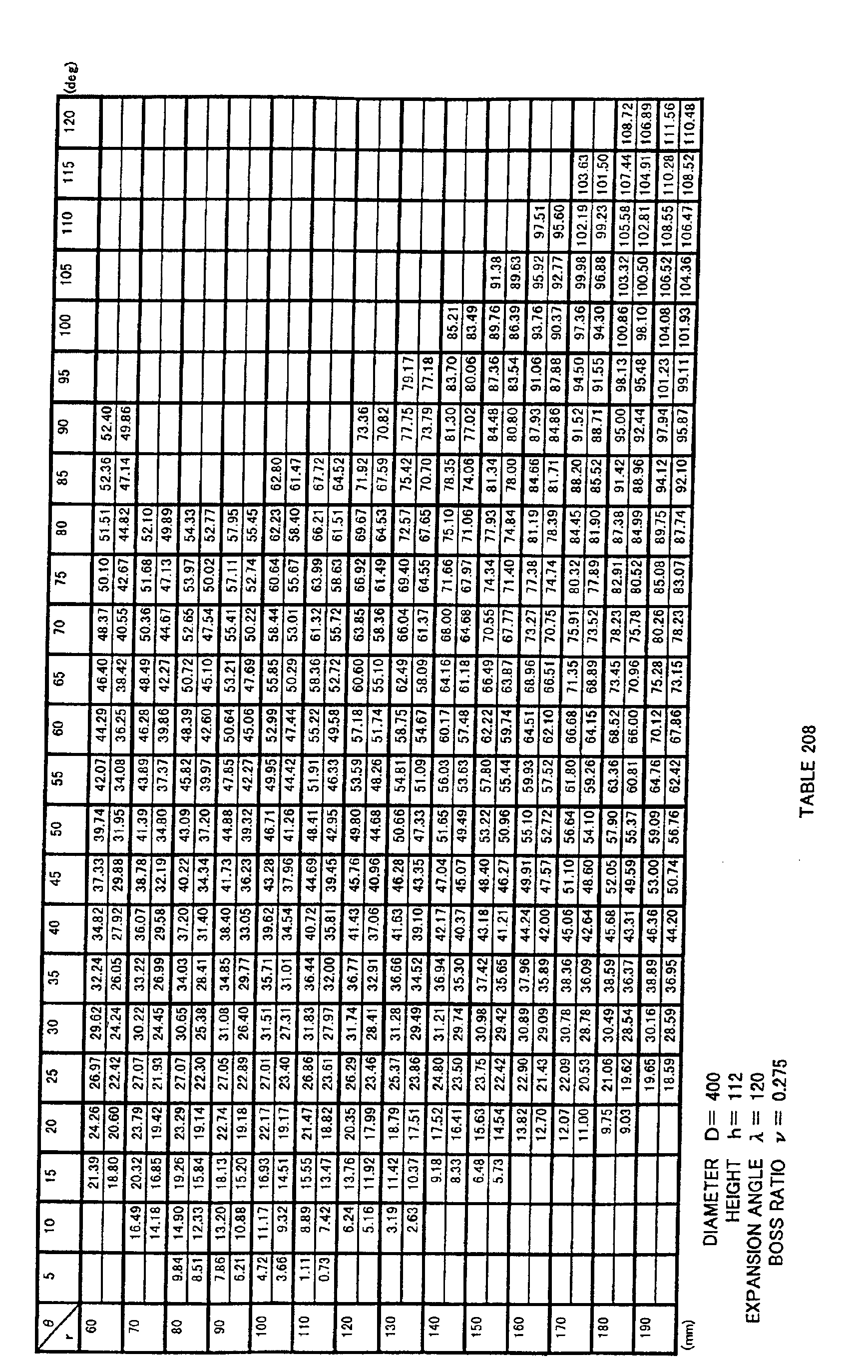
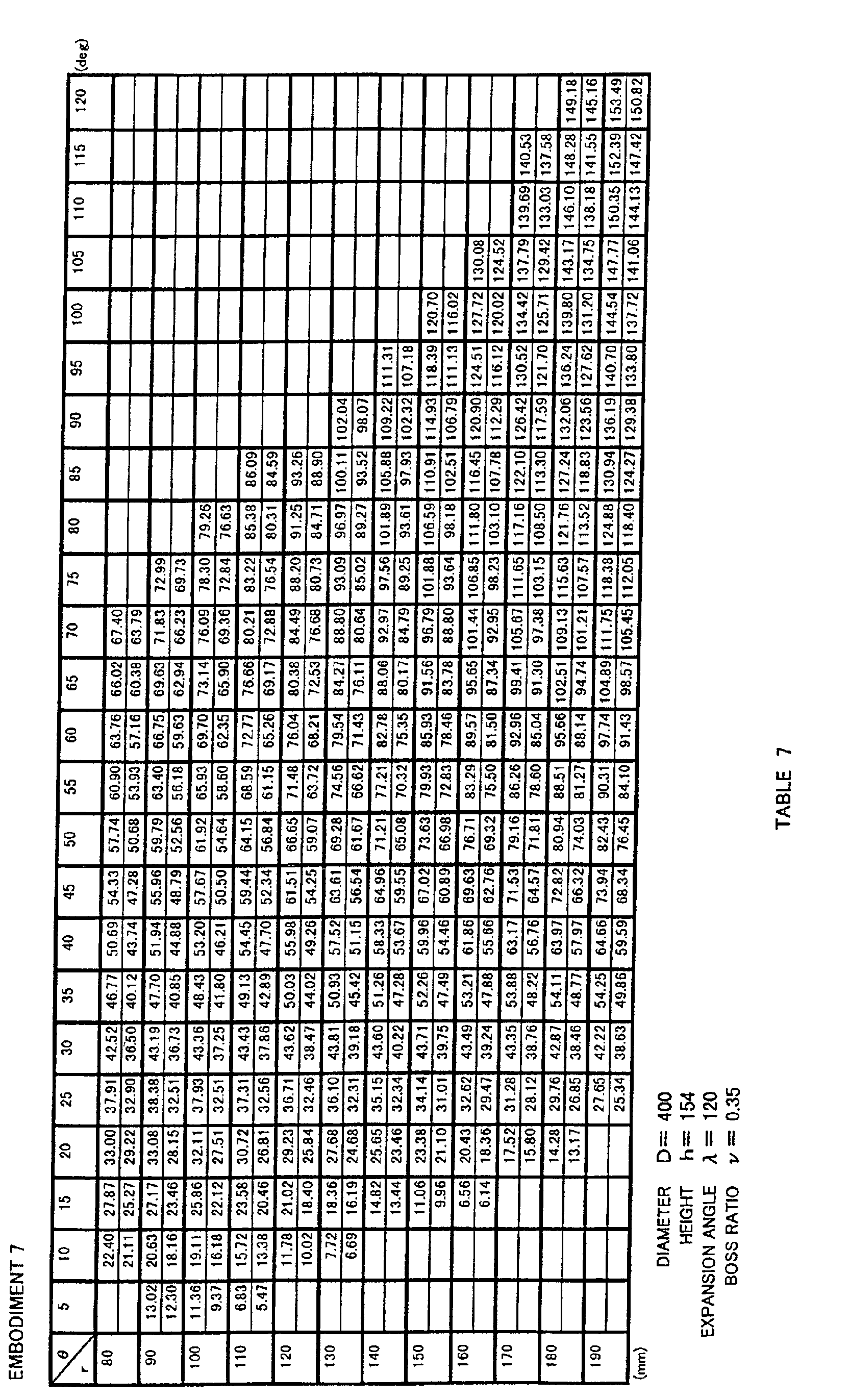
  • Fig. 1 for blade 3 of propeller fan 1, lines are drawn in the r direction that divide the blade at intervals of every 10 mm in the range between 80 mm and 190 mm, and lines are drawn that divide the blade in the ⁇ direction at intervals of every 5 deg in the range between 0 deg and 125 deg, a coordinate value of z at each crossing point being indicated in Table 5.
  • the top of each column indicates a value on the negative pressure surface side (suction side) of the propeller fan, whereas the bottom of each column indicates a value on the positive pressure surface side (blowing side).
  • each coordinate value of r, ⁇ , z at an outer edge portion of blade 3 having ⁇ within the range between 0 deg and 125 deg are indicated in Table 6.
  • blade 3 is made thicker at a root portion of blade 3.
  • shape of the surface of blade 3 may be smooth, or may be provided with concavities and convexities in a form of grooves, protrusions or dimples.
  • propeller fan 1 of the present invention may be molded in one piece by synthetic resin such as ABS (acrylonitrile-butadiene-styrene) resin or polypropylene (PP), or may be integrally molded in one piece by synthetic resin having an increased intensity by including mica or the like, or may be non-integrally molded.
  • synthetic resin such as ABS (acrylonitrile-butadiene-styrene) resin or polypropylene (PP)
  • PP polypropylene
  • Fig. 7 shows an example of a propeller-fan-molding die 4 for forming propeller fan 1 shown in Fig. 1.
  • Die 4 is for molding propeller fan 1 by synthetic resin, and has a fixed-side die 5 and a movable-side die 6, as shown in Fig. 7.
  • Coordinates (r 1 , ⁇ 1 , z 1u ) on the die surface of a portion forming the surface of blade 3 in fixed-side die 5 described above and coordinates (r 1 , ⁇ 1 , z 1d ) on the die surface of a portion forming the surface of blade 3 in movable-side die 6 are obtained by transforming non-dimensionally expressed three-dimensional coordinate values indicated in Tables 3 and 4 using a transformation formula 14 below.
  • fixed-side die 5 and movable-side die 6 have curved portions respectively specified by coordinate values indicated in Tables 5 and 6. It is noted that, in this case also, each curved surface may be specified by coordinate values within the range of ⁇ 5 % of each coordinate value.
  • the dimension of the curved shape of the die may be determined in consideration of mold shrinkage.
  • the coordinate data above may be corrected in consideration of the mold shrinkage, warping and deformation, to form molding die 4, such that propeller fan 1 having blade 3 with a three-dimensional curved surface specified by coordinate values within the range of ⁇ 5 % of three-dimensional coordinate values indicated in Tables 5 and 6 above is formed after the mold shrinkage, and these are encompassed by the molding die of the present invention.
  • die 4 for molding the propeller fan in the present embodiment includes the negative pressure side surface of propeller fan 1 formed by fixed-side die 5 and a positive pressure side surface of propeller fan formed by movable-side die 6 as shown in Fig. 7, it may be possible to form the positive pressure side surface of propeller fan 1 by fixed-side die 5 and the negative pressure side surface of propeller fan 1 by movable-side die 6.
  • Fig. 4 is a front view of a propeller fan in Comparison Example 1
  • Figs. 5 and 6 are perspective views of the propeller fan in Comparison Example 1.
  • a boss portion is denoted by 2 in the drawings. Note that r, ⁇ , z are set as in Embodiment 1.
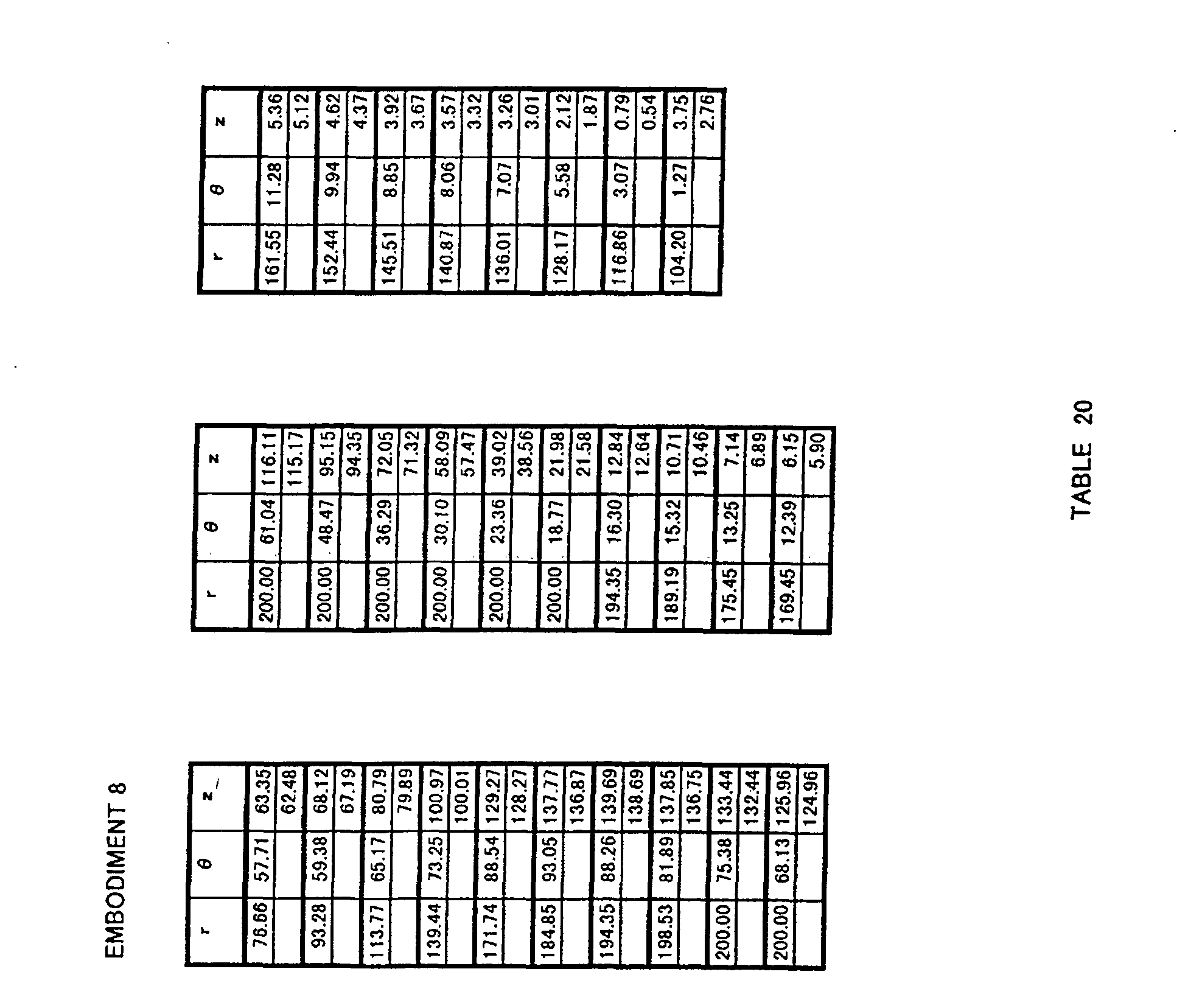
  • Each of the propeller fans as in Embodiments 1 to 20 and those in Comparison Examples 1 to 3 is attached to an outdoor unit of an air conditioner, and airflow, power consumption and noise are measured.
  • each fan in Embodiments 1 to 13 and in Comparison Example 1 having the fan diameter of ⁇ 400 was driven by a DC motor using an outdoor unit with a refrigeration capacity of a 28 kW class.
  • the results are shown in Table 48 below.
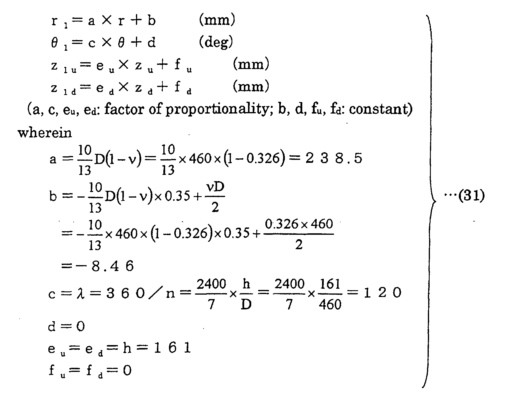
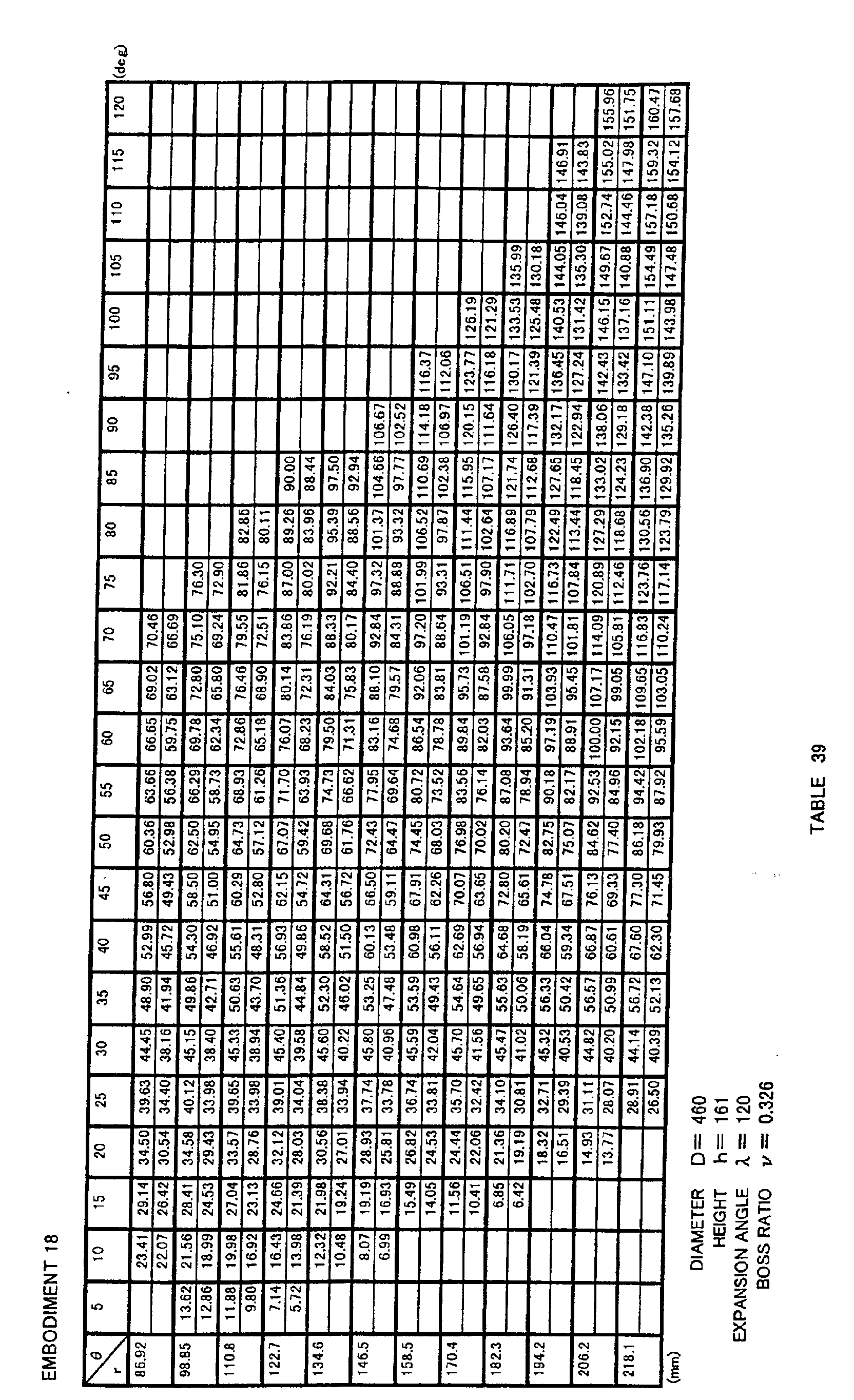
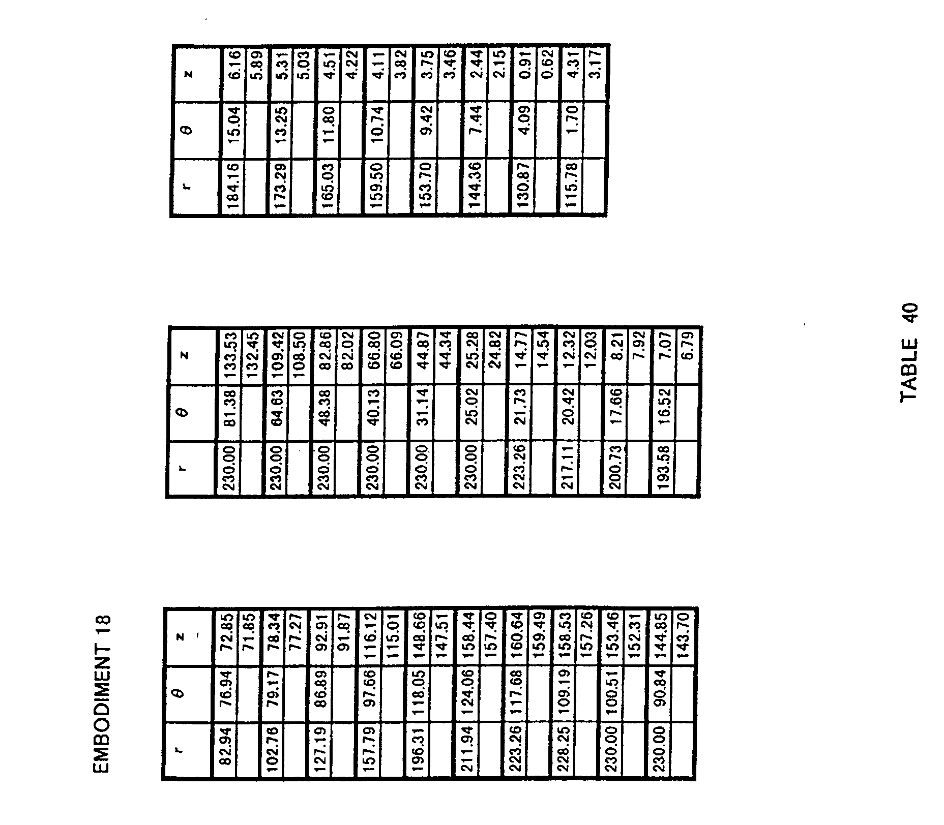
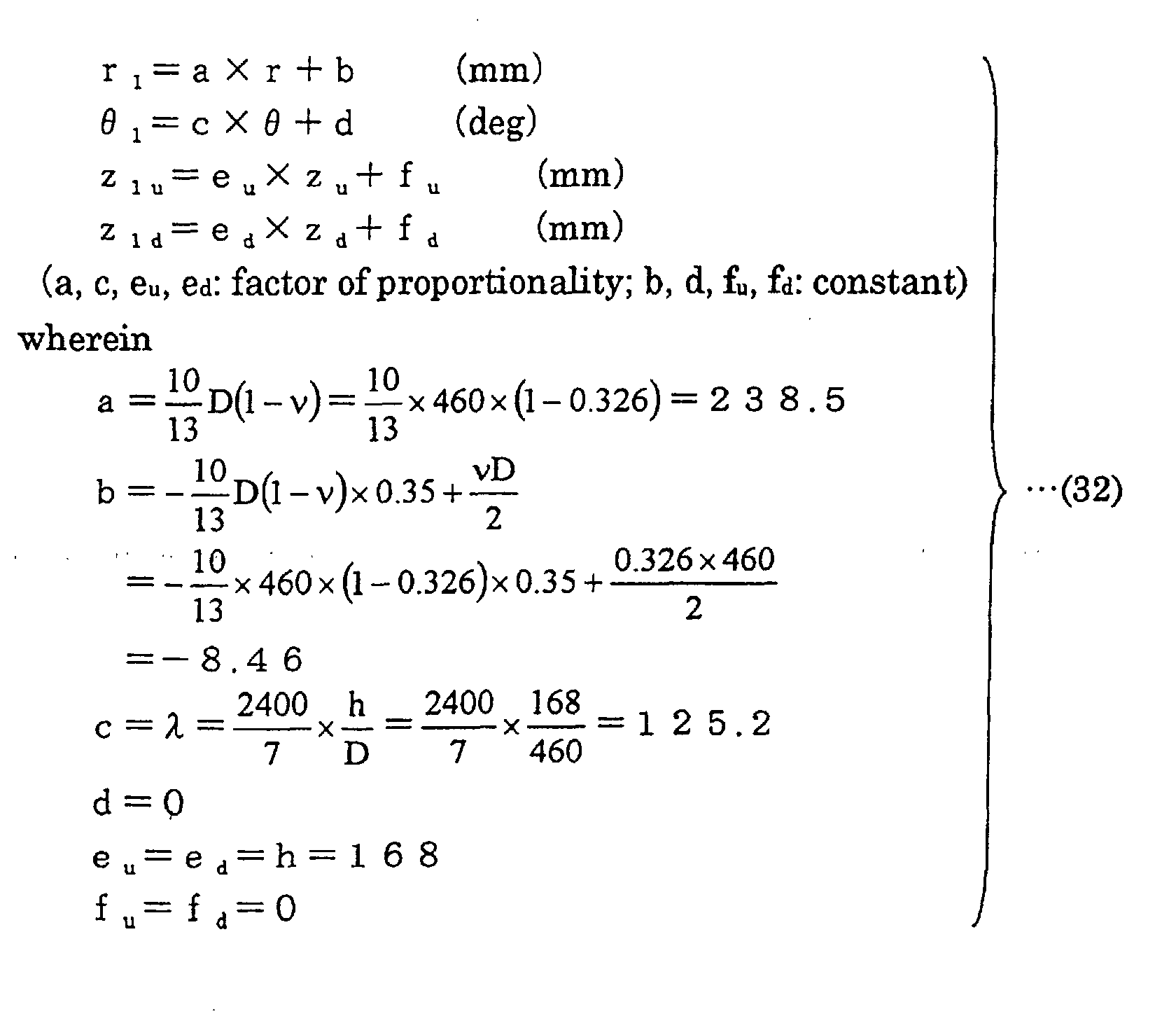
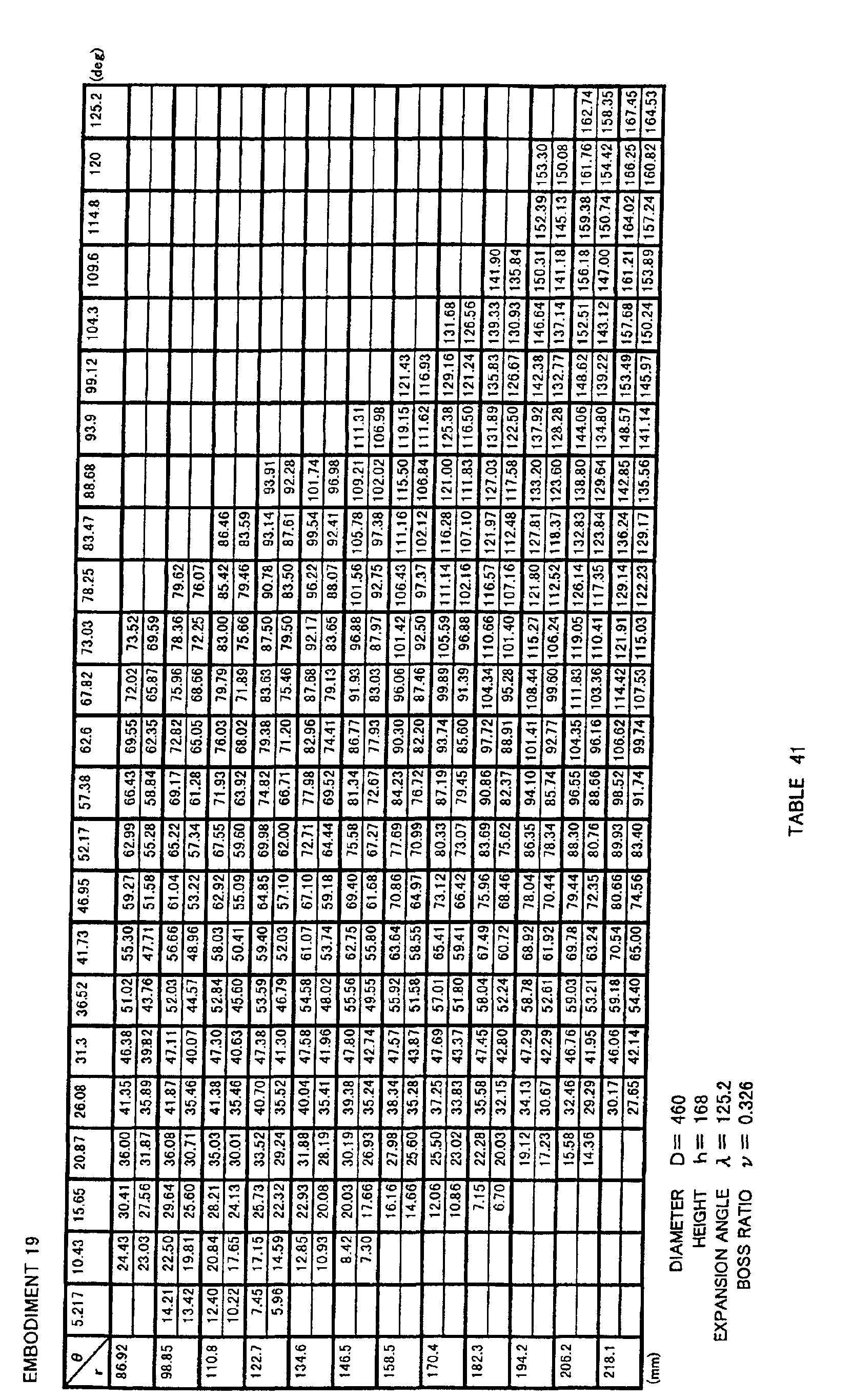
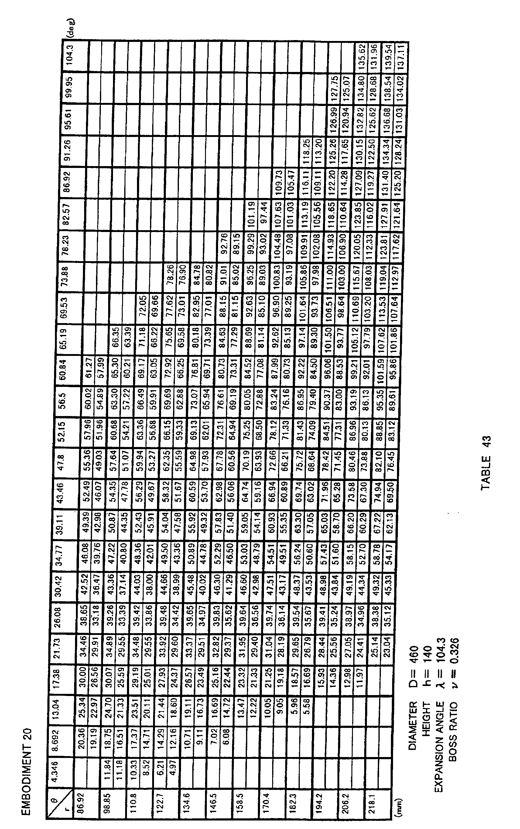
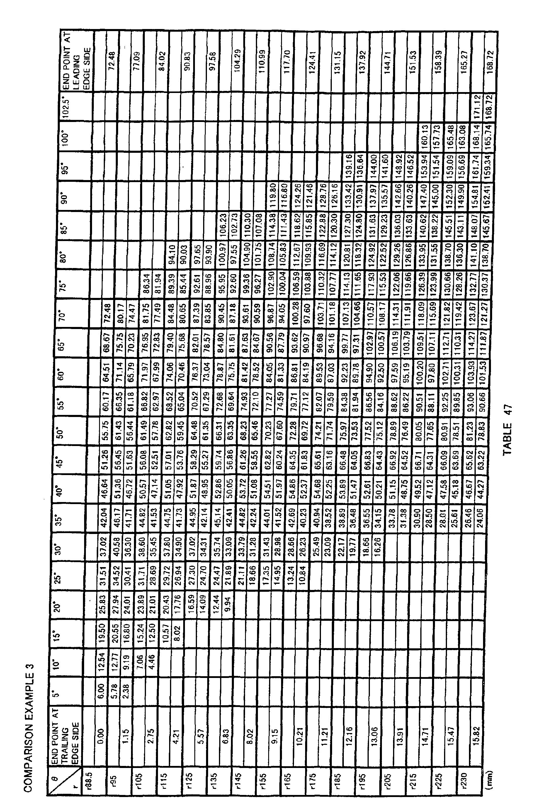
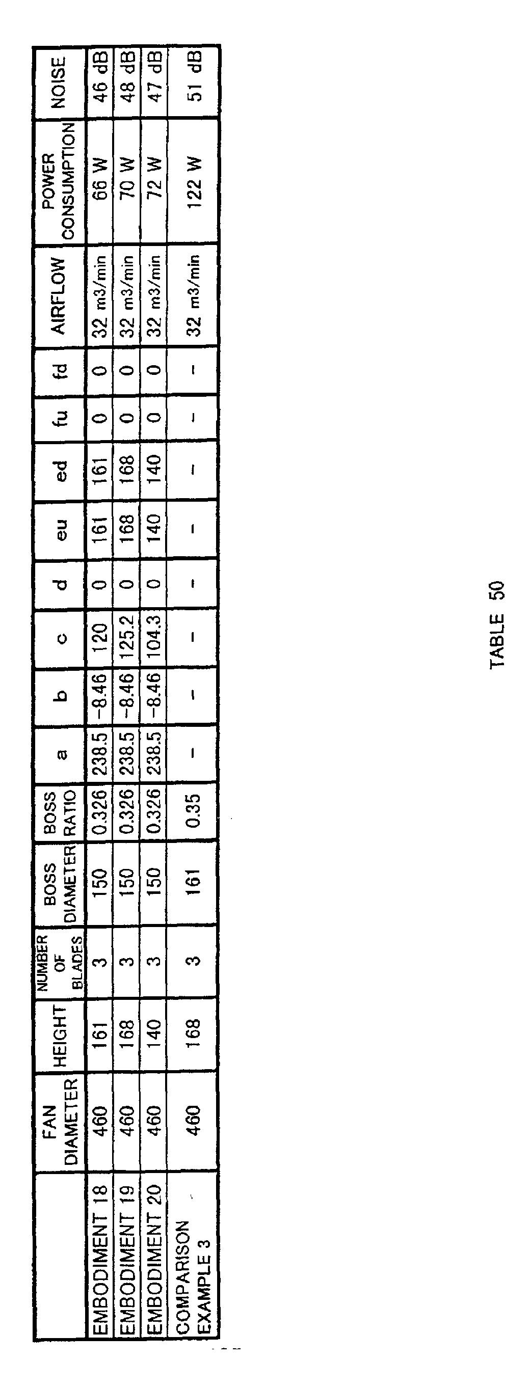
  • each fan in Embodiments 18 to 20 and in Comparison Example 3 having the fan diameter of ⁇ 460 was driven by an AC motor using a multiple-type large outdoor unit.
  • the results are shown in Table 50 below.
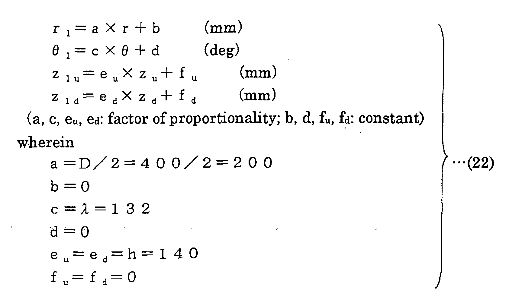
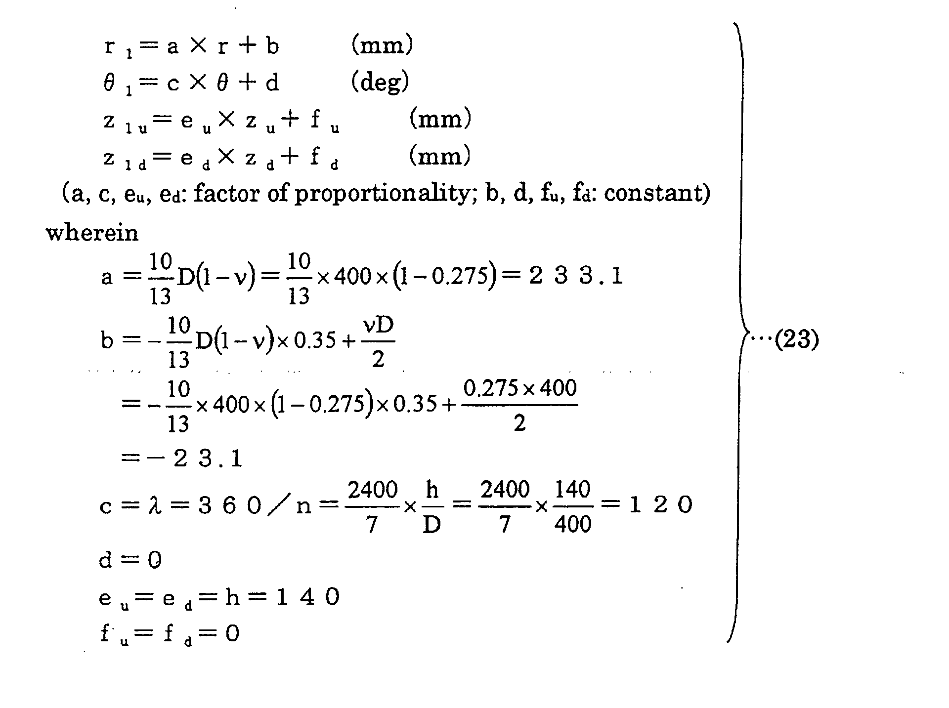
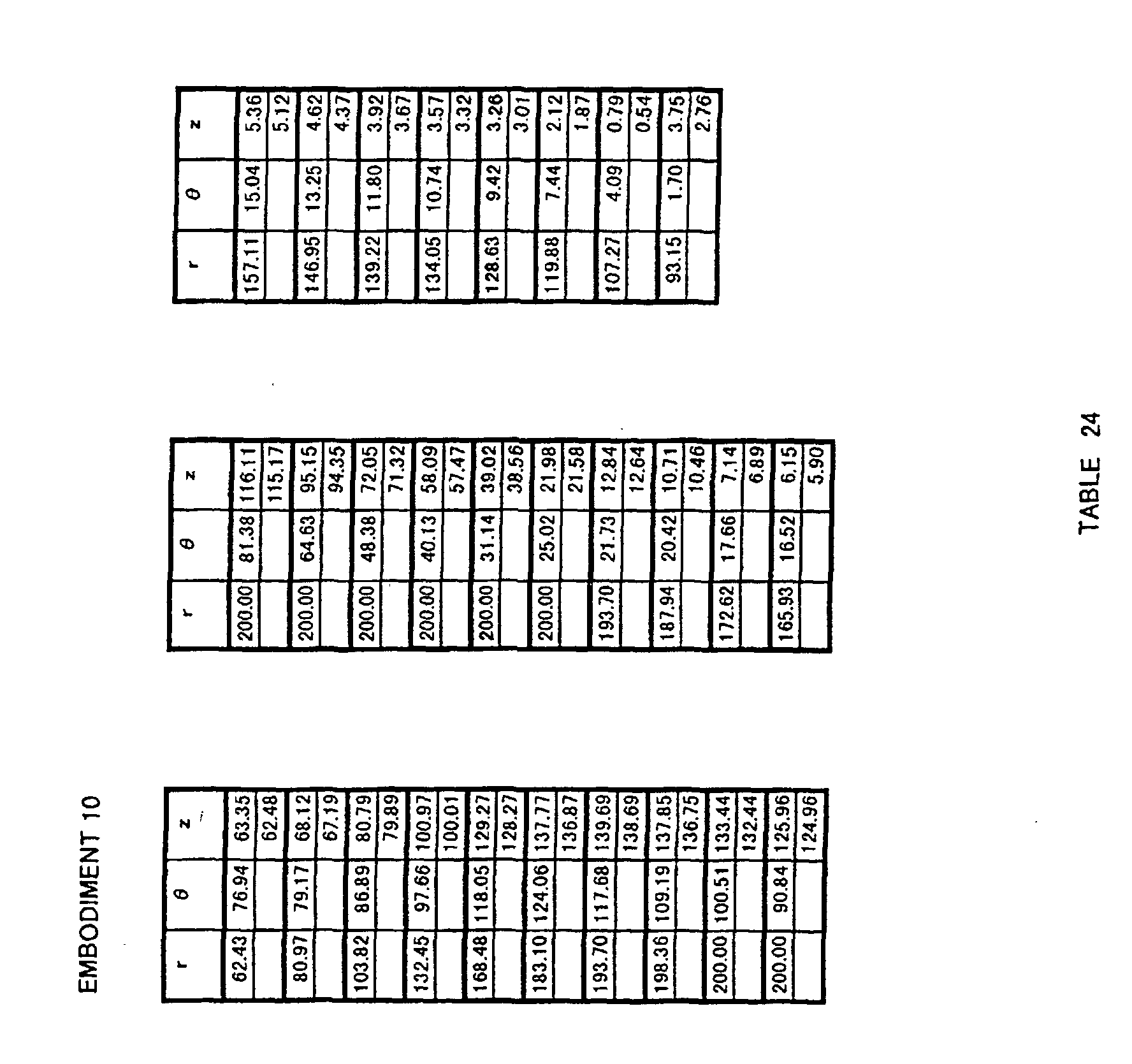
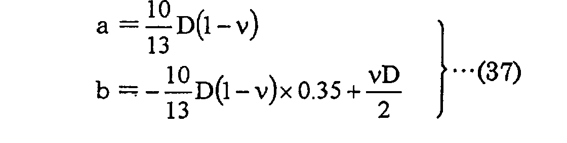
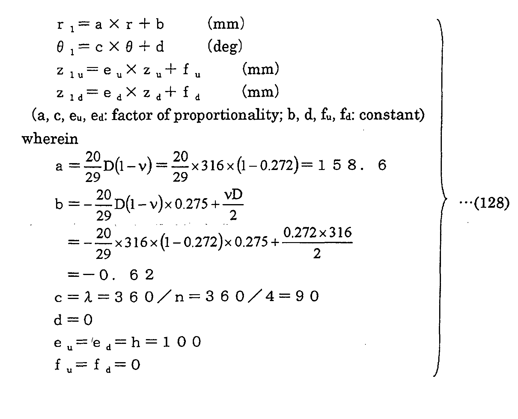
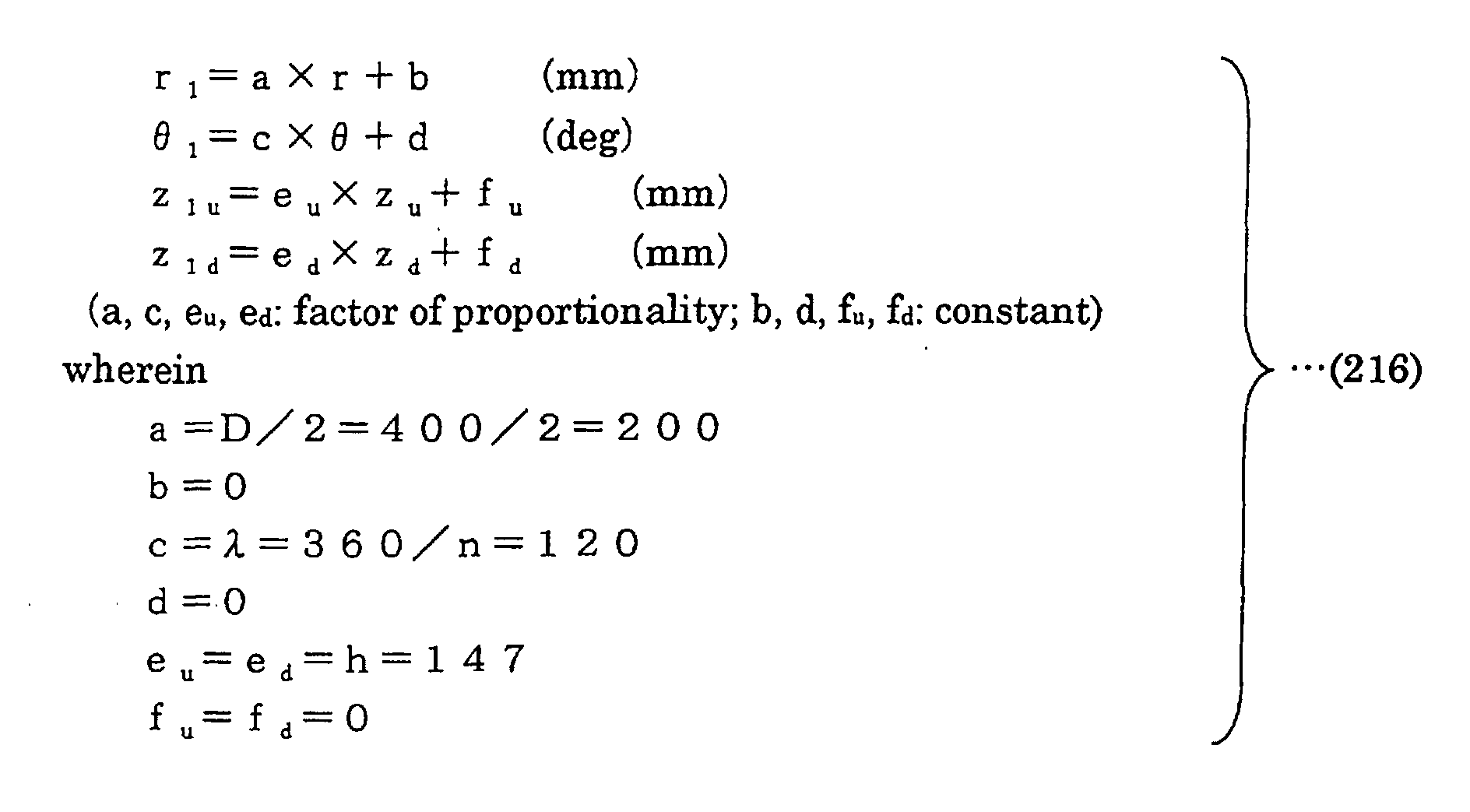
  • Embodiment 10 showed a superiority in efficiency and noise as in Embodiment 1, since, in Embodiment 10, transformation satisfying an equation 37 below is performed for Embodiment 1.
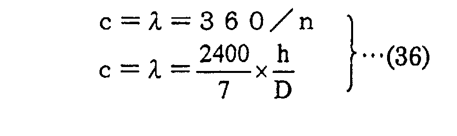
  • the ratio of h/D is smaller, i.e., the thickness of a wing is thinner, than that in Embodiment 1.
  • the wing is largely deformed at rotation of the fan due to the centrifugal force applied on the wing (blade), reducing the height of the wing, and therefore degradation occurs in terms of efficiency and noise.
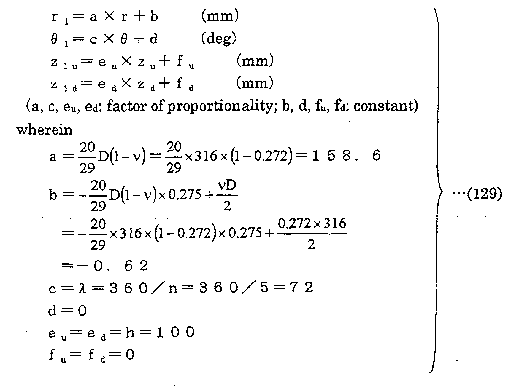
  • Embodiments 16 and 17 in Table 49 above were compared with each other, Embodiment 17 was superior to Embodiment 16.
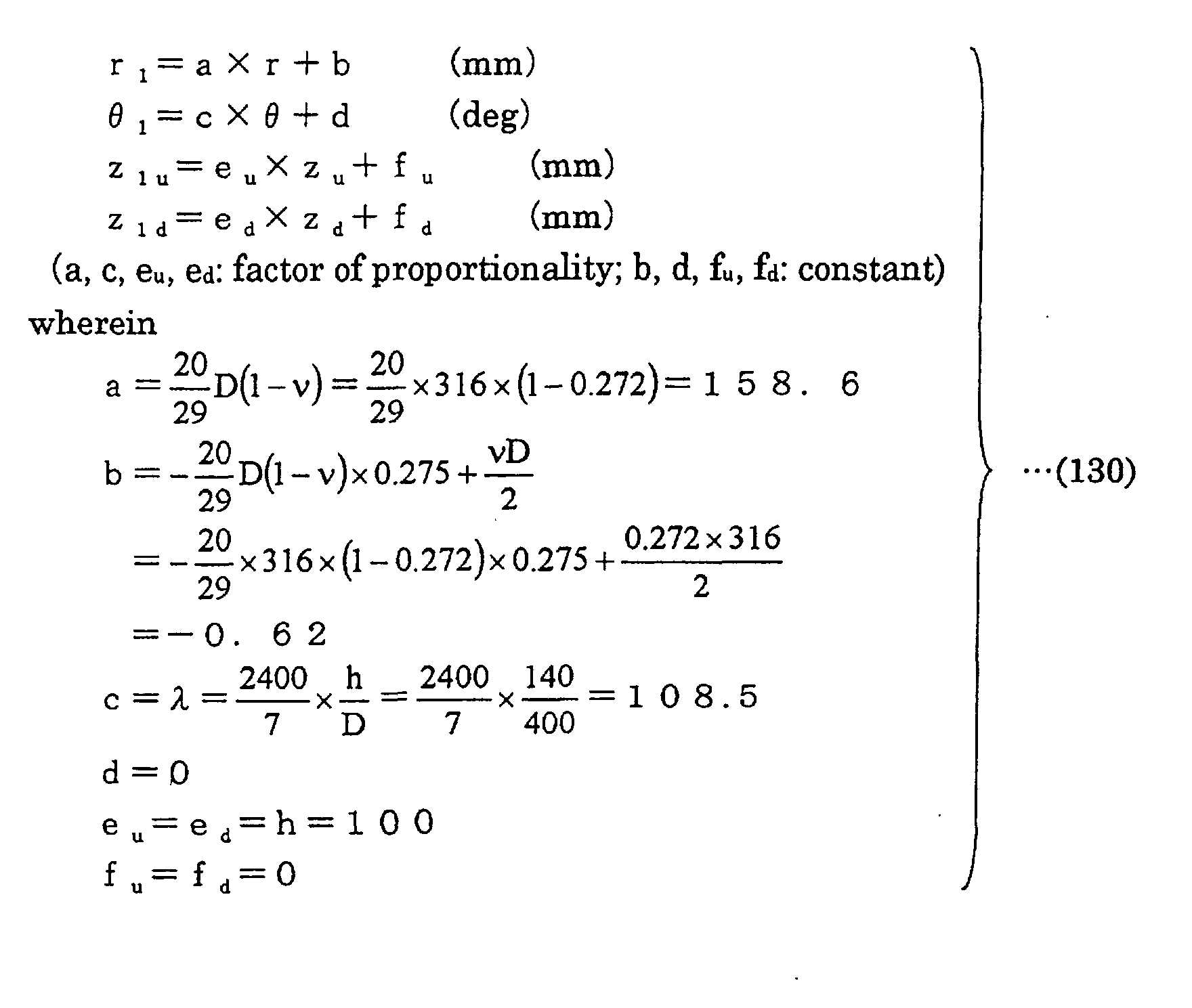
  • Embodiment 18 was superior to Embodiments 19 and 20.
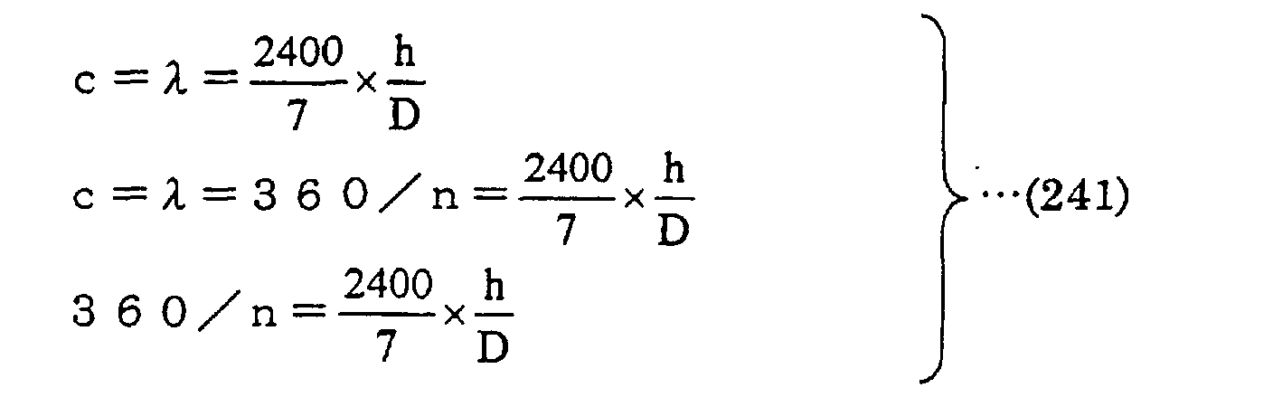
  • selection is made not only for ⁇ to satisfy the first equation (the top equation) in an equation 41 below, but also for the number of blades n, blade expansion angle ⁇ and height h to satisfy the second equation (the middle equation) in equation 41 below, to achieve a higher superiority. That is, in respect to the propeller fan according to the present invention, the third equation (the bottom equation) in equation 41 below is important to determine a design manual.
  • a fluid feeding device 7 shown in Fig. 8 includes a blower 9 constituted by propeller fan 1 in Embodiment 1 and a drive motor 8, and feeds fluid out by blower 9.
  • Fluid feeding device 7 in the present embodiment is an outdoor unit 10 of an air conditioner.
  • Outdoor unit 10 includes an outdoor heat exchanger 11, and efficiently exchanges heat by blower 9 described above.
  • blower 9 is installed in outdoor unit 10 by a motor angle 12, and a supply opening 13 of outdoor unit 10 is formed to be a bell mouth 14 as shown in Fig. 9.
  • blower 9 having a ring splasher 15 installed on the periphery of propeller fan 1, as shown in Fig. 10, may also be provided at fluid feeding device 7.
  • fluid feeding device 7 in an air conditioner of a type having an indoor unit and an outdoor unit formed in one piece to be attached to a window or the like, drain water may be splashed up and sprayed on outdoor heat exchanger 11, to further increase the efficiency.
  • Outdoor unit 10 in the present embodiment is a quiet outdoor unit with reduced noise, since propeller fan 1 in Embodiment 1 is included therein. Moreover, propeller fan 1 has an increased fan efficiency, so that an efficient outdoor unit realizing energy-saving can be attained. It is presumed that propeller fans in other Embodiments can attain similar results.
  • Fig. 11 shows a front view of propeller fan 1 of the present invention.
  • Propeller fan 1 of the present invention is molded in one piece by synthetic resin such as, for example, AS resin with glass fiber.
  • the diameter D 400 mm
  • the height in the axial direction (z direction) h 140 mm
  • the number of blades n 3
  • three blades 3 are radially and integrally provided on the periphery of boss portion 2.
  • the shape of the surface of blade 3 of propeller fan 1 is obtained based on a base shape defined by specific coordinate values.
  • the shape of a curved surface which is defined by coordinate values obtained by transforming the coordinate values in the base shape in the r, ⁇ and z directions using prescribed transformation formulas respectively, is determined as the shape of the surface of blade 3 of propeller fan 1.
  • the base shape of the present invention is typically defined by the coordinate values indicated in Table 102 described earlier.
  • the shape which is defined by coordinate values obtained by uniformly transforming the coordinate values indicated in Table 102 by e.g. multiplying the coordinate values with prescribed coefficients, should also be interpreted as equivalent to the base shape of the present invention.
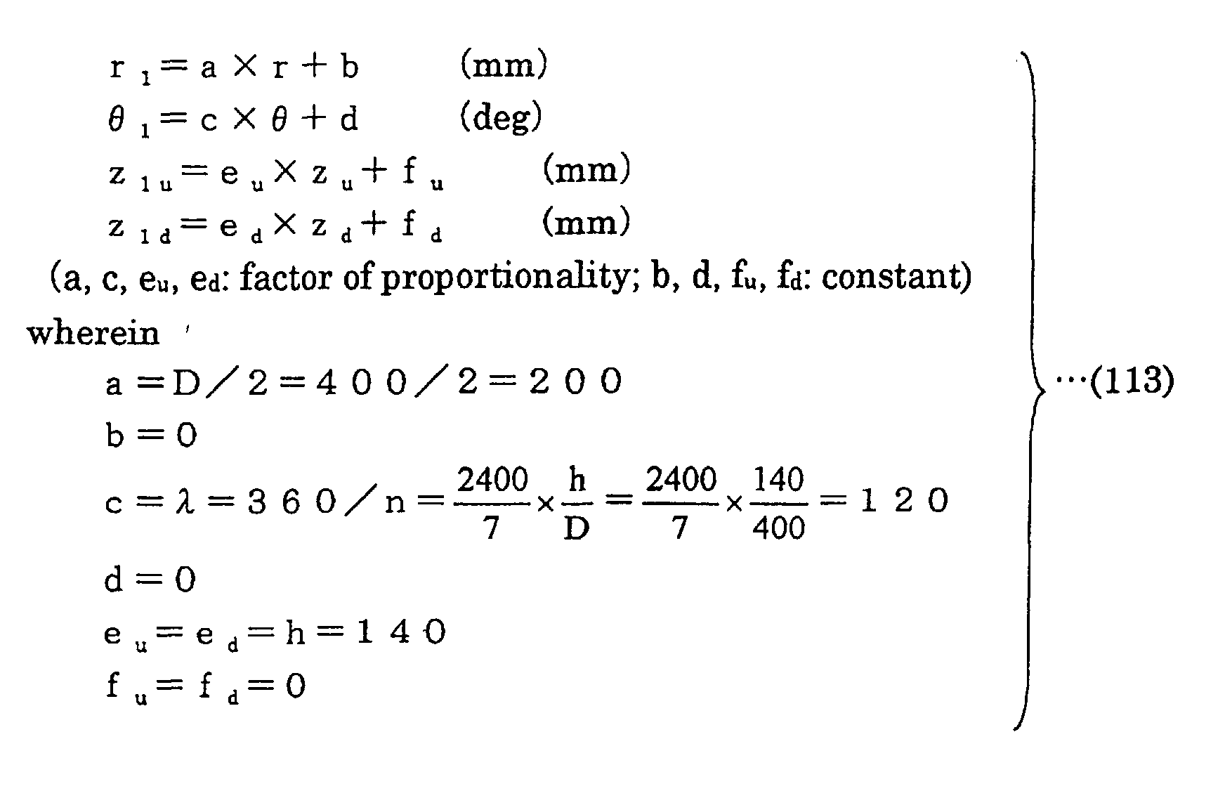
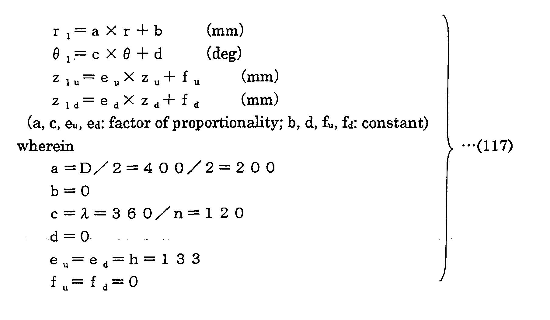
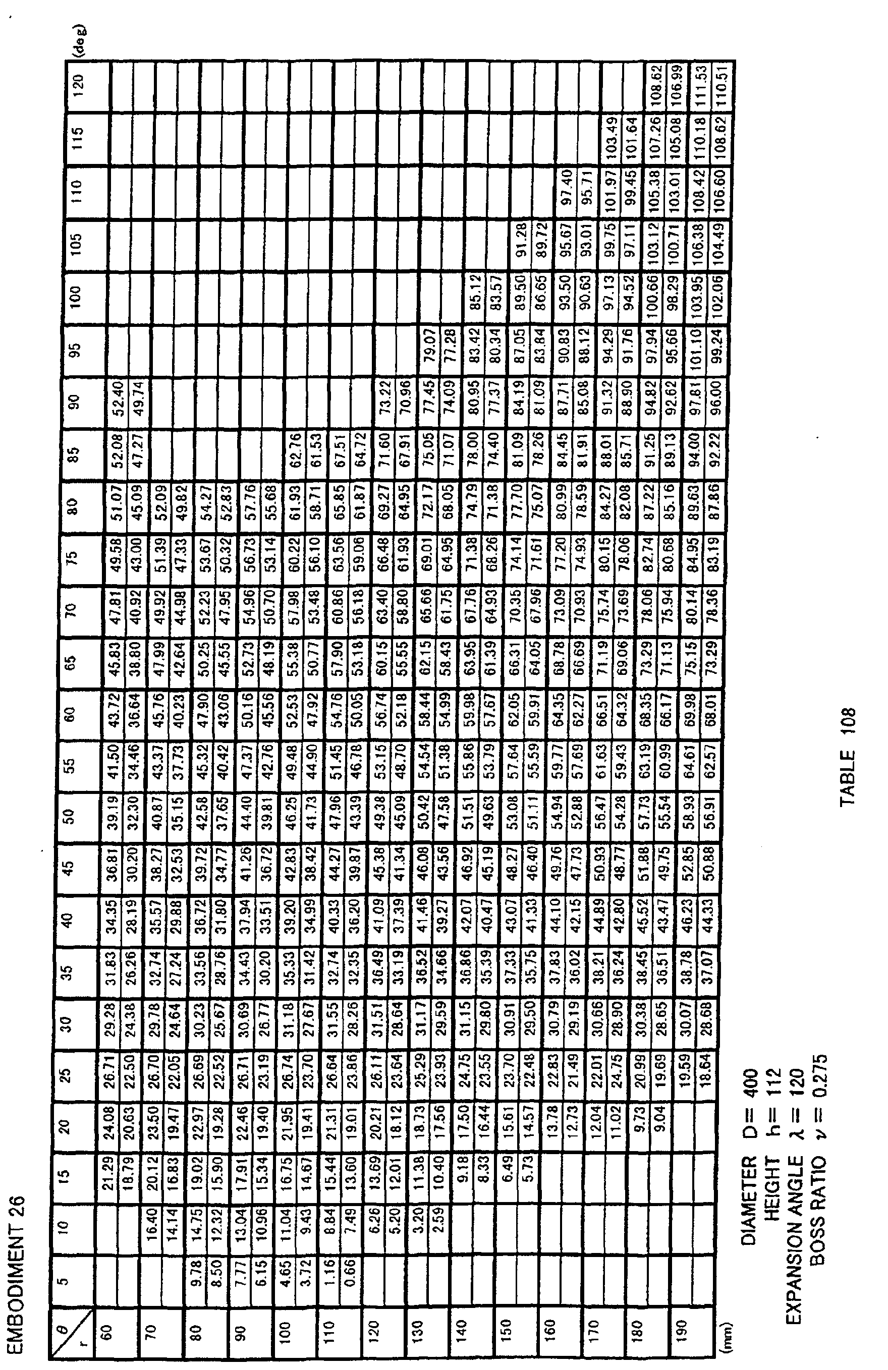
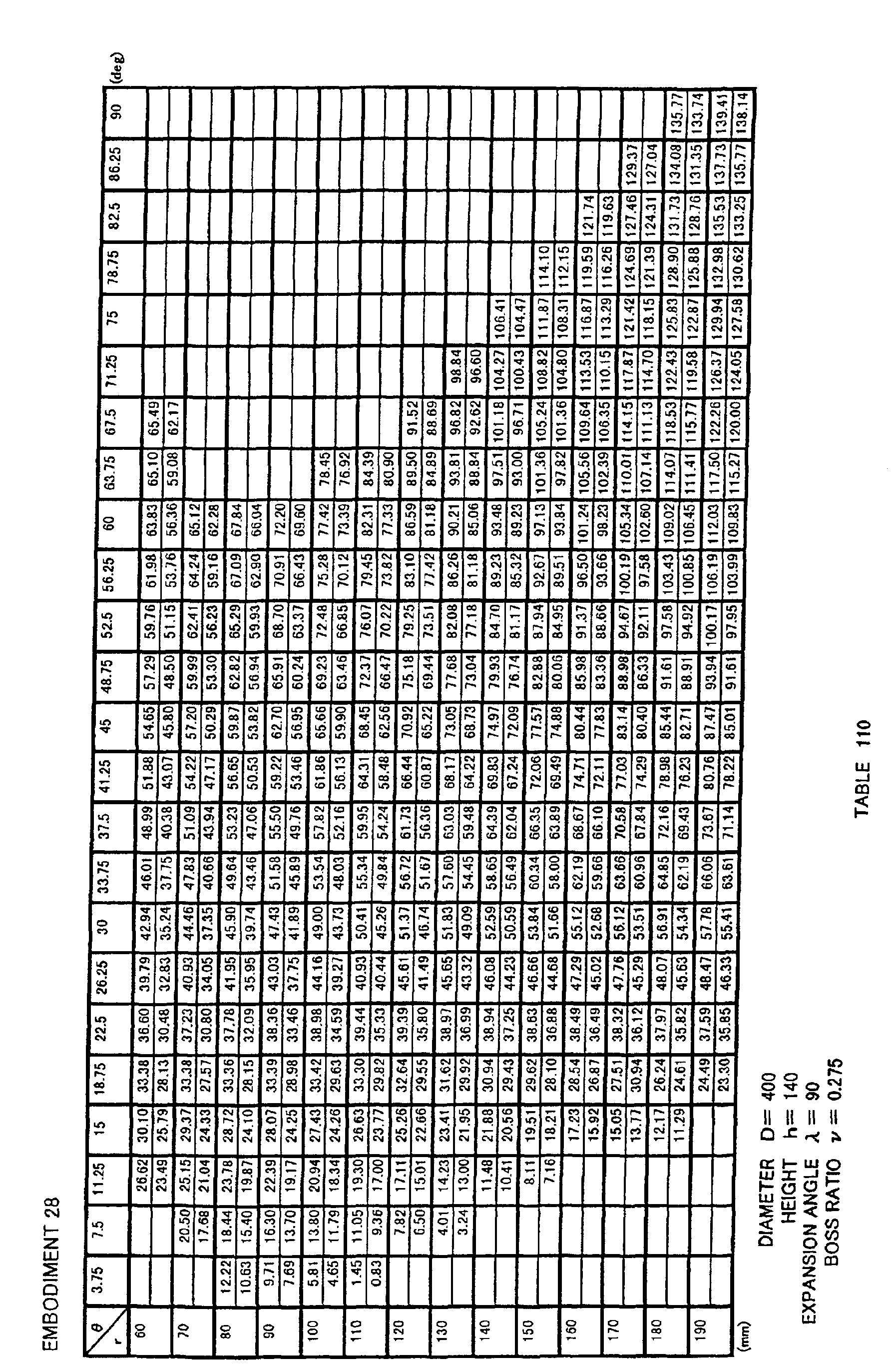
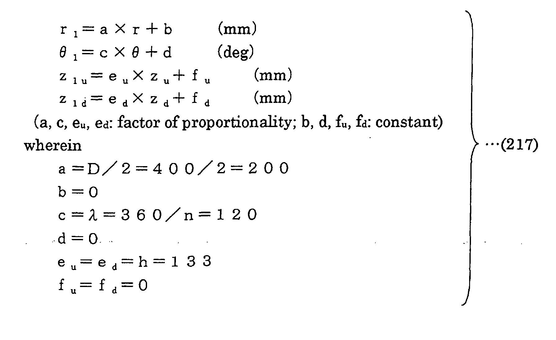
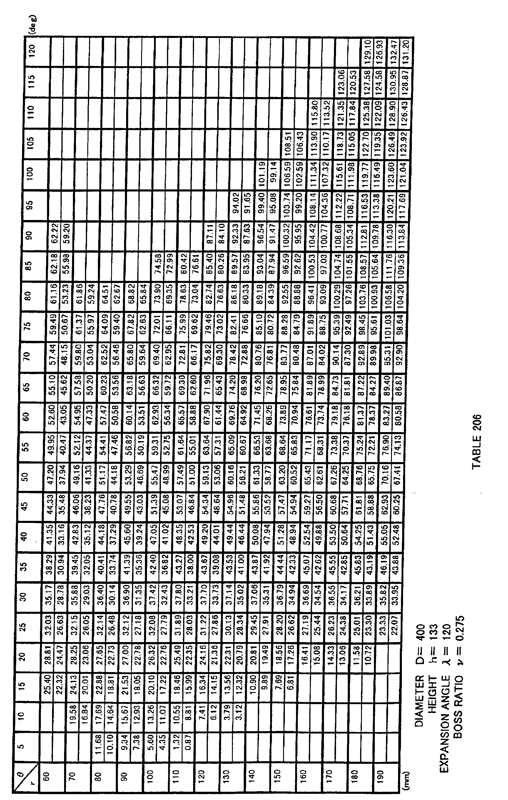
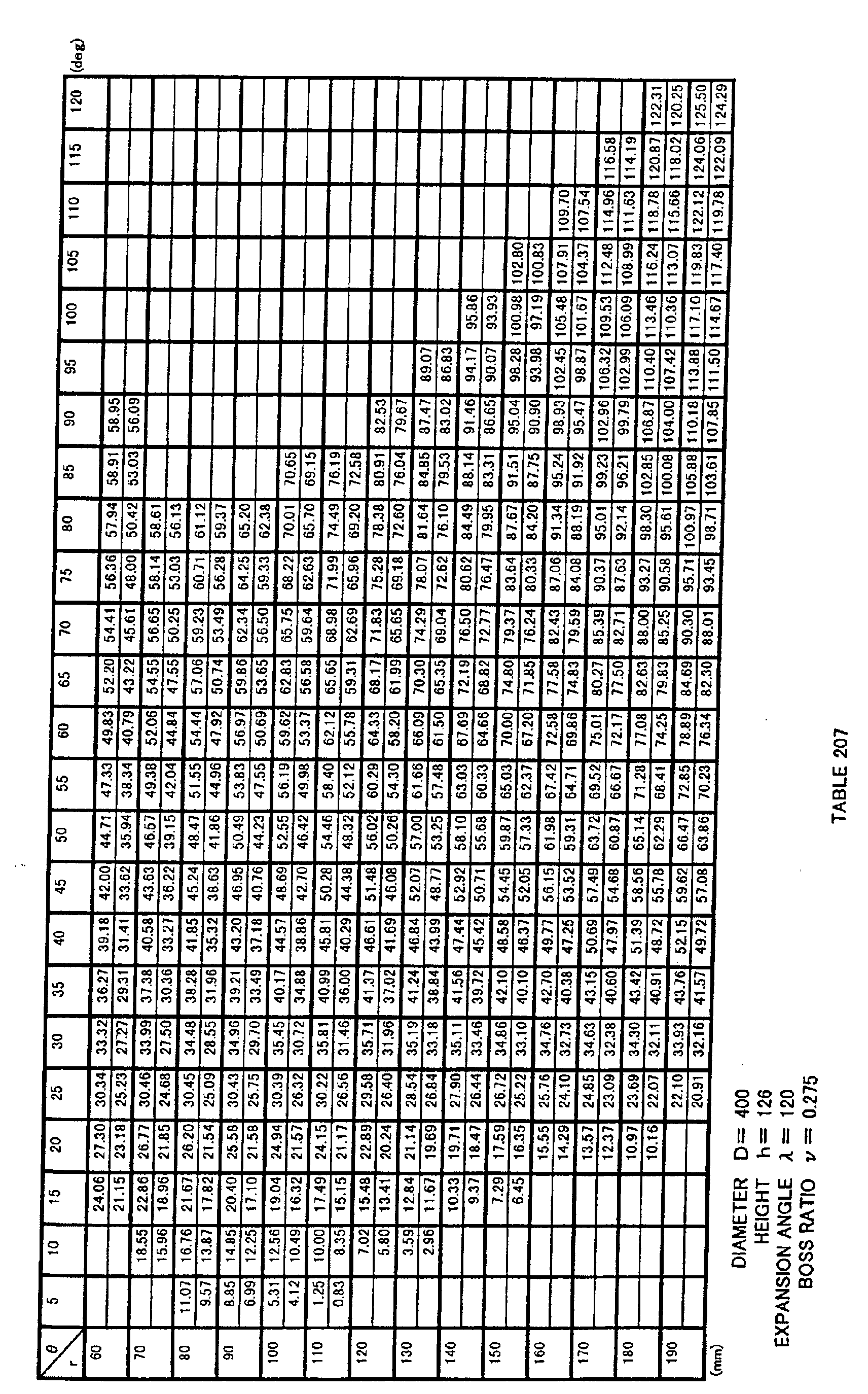
  • coordinates (r 1 , ⁇ 1 , z 1u ) of a surface on a negative pressure side of blade 3 and coordinates (r 1 , ⁇ 1 , z 1d ) of a surface on a positive pressure side of blade 3 are coordinate values obtained by transforming non-dimensionally expressed three-dimensional coordinate values indicated in Table 102 using a transformation formula 113 below, and the surface on the negative pressure side and the surface on the positive pressure side are configured by curved surfaces defined by the obtained coordinate values, i.e. a curved surface specified by coordinate values indicated in Table 103.
  • the curved surface may also be specified by coordinate values within the range of ⁇ 5 % of each coordinate value.
  • Fig. 11 shows a cylindrical coordinate system of r and ⁇ by dashed lines. It is noted that, though the z axis is not shown in Fig. 11, the z axis is a line passing the center of rotation 0 of boss portion 2 of propeller fan 1 in Fig. 11 and perpendicular to the plane of the drawing (that is, a line overlapping with a core of the rotation axis of propeller fan 1).
  • Fig. 11 for blade 3 of propeller fan 1, lines are drawn in the r direction that divide the blade at intervals of every 10 mm in the range between 60 mm and 190 mm, and lines are drawn that divide the blade in the ⁇ direction at intervals of every 5 deg in the range between 0 deg and 125 deg, a coordinate value of z at each crossing point being indicated in Table 103.
  • the top of each column indicates a value on the negative pressure surface side (suction side) of the propeller fan, whereas the bottom of each column indicates a value on the positive pressure surface side (blowing side) thereof.
  • propeller fan 1 of the present invention may be molded in one piece by synthetic resin such as ABS (acrylonitrile-butadiene-styrene) resin or polypropylene (PP), or may be integrally molded in one piece by synthetic resin having an increased intensity by including mica or the like, or may be non-integrally molded.
  • synthetic resin such as ABS (acrylonitrile-butadiene-styrene) resin or polypropylene (PP)
  • PP polypropylene
  • Fig. 17 shows an example of a propeller-fan-molding die 4 for forming propeller fan 1 shown in Fig. 11.
  • Die 4 is for molding propeller fan 1 by synthetic resin, and has a fixed-side die 5 and a movable-side die 6, as shown in Fig. 17.
  • Coordinates (r 1 , ⁇ 1 , z 1u ) on the die surface of a portion forming the surface of blade 3 in fixed-side die 5 described above and coordinates (r 1 , ⁇ 1 , z 1d ) on the die surface of a portion forming the surface of blade 3 in movable-side die 6 are obtained by transforming non-dimensionally expressed three-dimensional coordinate values indicated in Table 102 using a transformation formula 114 below.
  • fixed-side die 5 and movable-side die 6 have curved portions respectively specified by coordinate values indicated in Table 103. It is noted that, in this case also, each curved surface may be specified by coordinate values within the range of ⁇ 5 % of each coordinate value.
  • the dimension of the curved surface of the die may be determined in consideration of mold shrinkage.
  • the coordinate data above may be corrected in consideration of the mold shrinkage, warping and deformation, to form molding die 4, such that propeller fan 1 having blade 3 with a three-dimensional curved surface specified by coordinate values within the range of ⁇ 5 % of three-dimensional coordinate values indicated in Table 103 above is formed after the mold shrinkage, and these are encompassed by the molding die of the present invention.
  • die 4 for molding the propeller fan in the present embodiment includes the negative pressure side surface of propeller fan 1 formed by fixed-side die 5 and a positive pressure side surface of propeller fan formed by movable-side die 6 as shown in Fig. 17, it may be possible to form the positive pressure side surface of propeller fan 1 by fixed-side die 5 and the negative pressure side surface of propeller fan 1 by movable-side die 6.
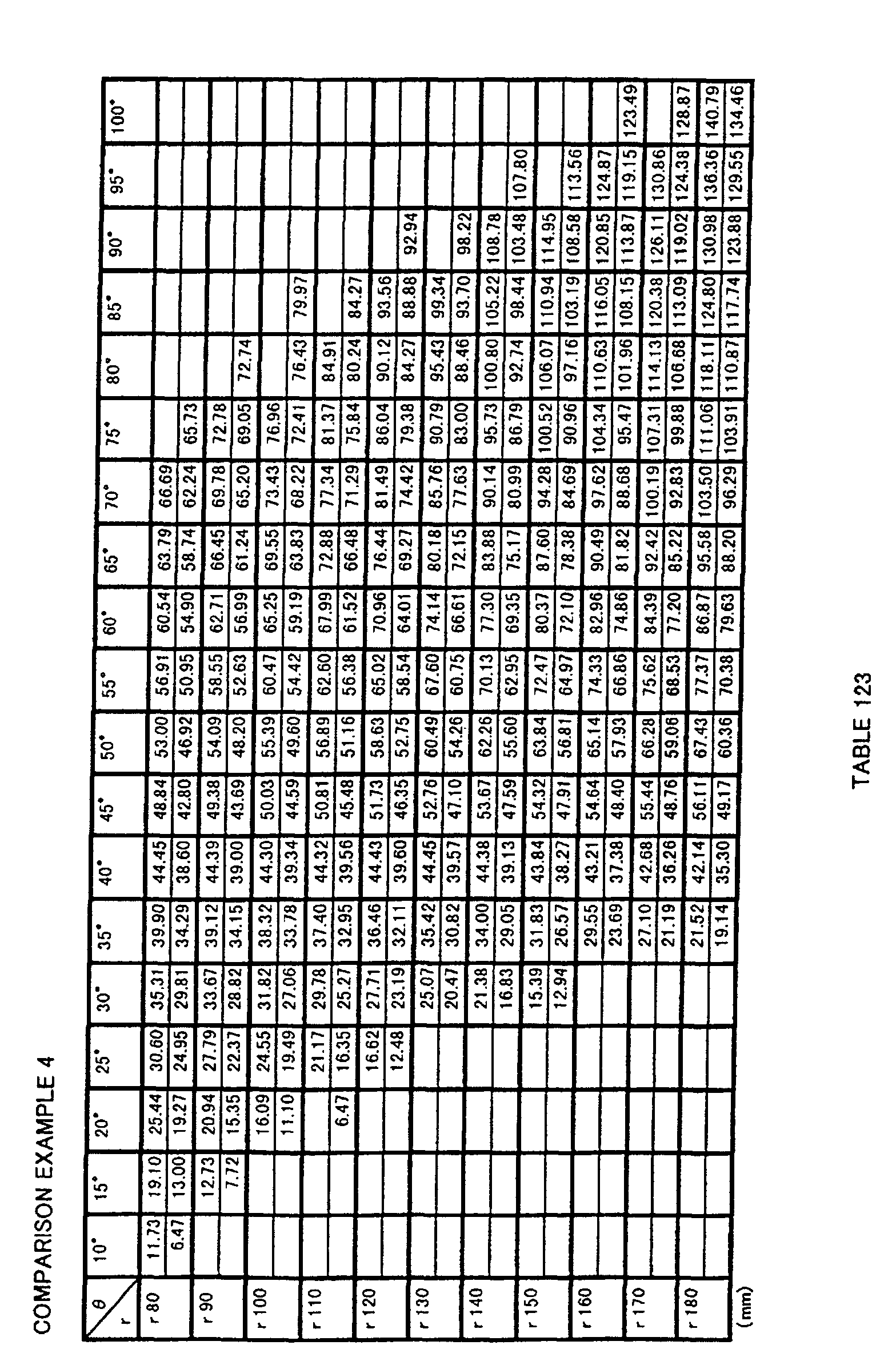
  • Fig. 14 is a front view of a propeller fan in Comparison Example 4
  • Figs. 15 and 16 are perspective views of the propeller fan in Comparison Example 4.
  • a boss portion is denoted by 2 in the drawings. Note that r, ⁇ , z are set as in Embodiment 21.
  • Each of the propeller fans as in Embodiments 21 to 40 and those in Comparison Examples 4 to 6 is attached to an outdoor unit of an air conditioner, and airflow, power consumption and noise are measured.
  • each fan in Embodiments 21 to 33 and in Comparison Example 4 having the fan diameter of ⁇ 400 was driven by a DC motor using an outdoor unit with a refrigeration capacity of a 28 kW class.
  • the results are shown in Table 126 below.
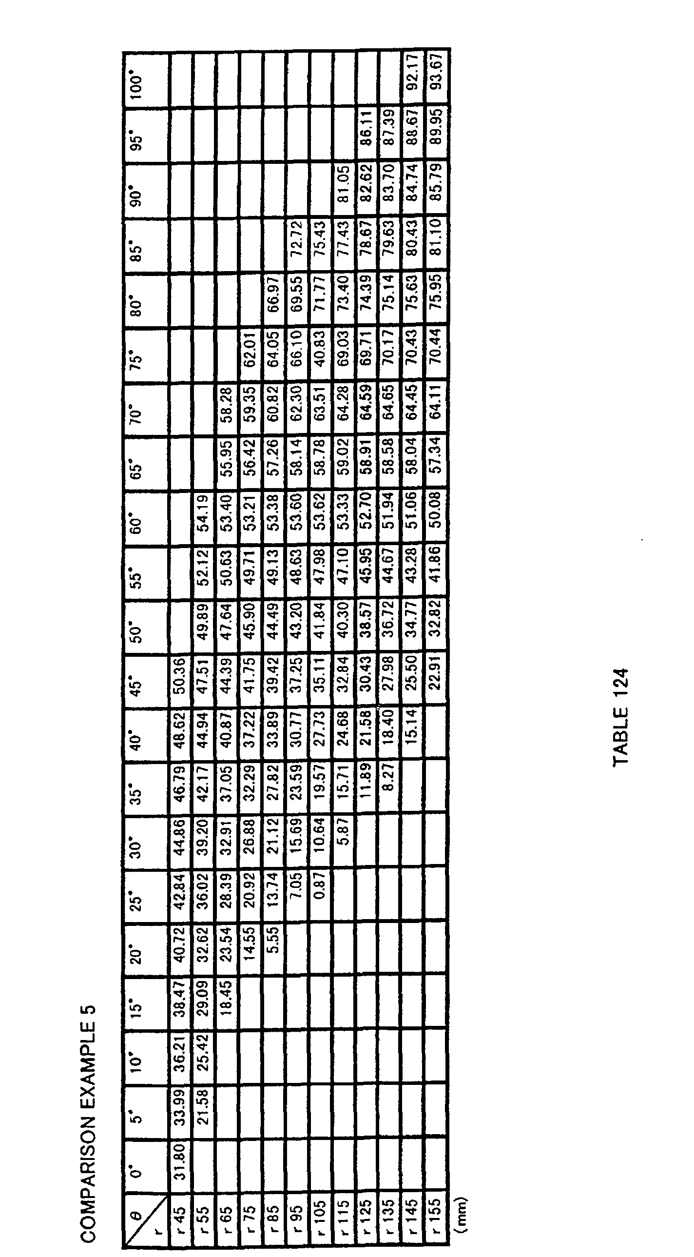
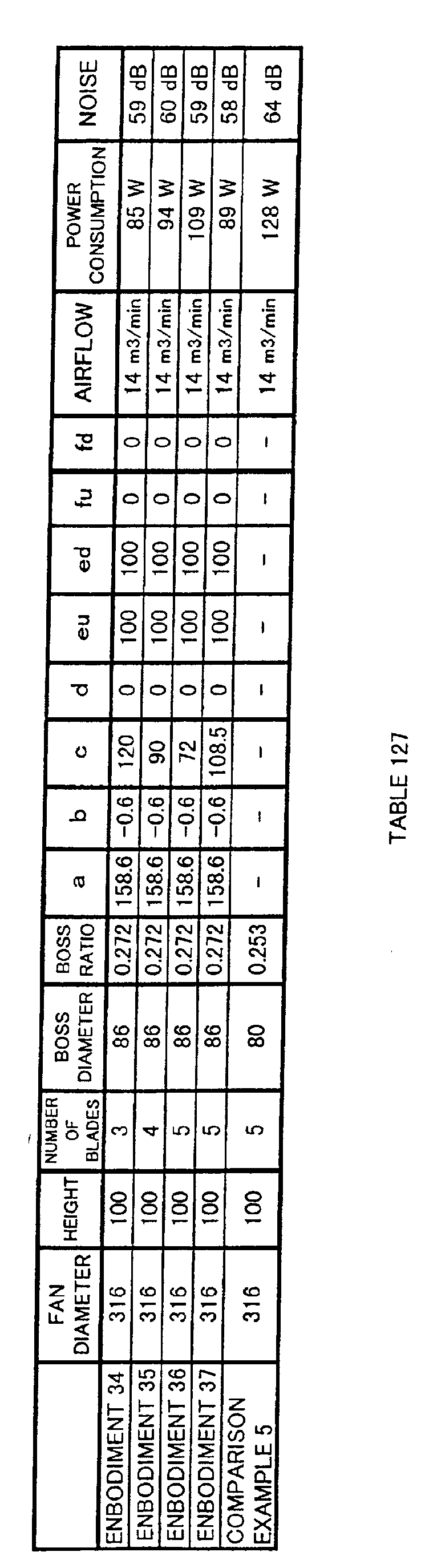
  • each fan in Embodiments 34 to 37 and in Comparison Example 5 having the fan diameter of ⁇ 316 was driven by an AC motor using an outdoor unit of a built-in type.
  • the results are shown in Table 127 below.
  • each fan in Embodiments 38 to 40 and in Comparison Example 6 having the fan diameter of ⁇ 460 was driven by an AC motor using a multiple-type large outdoor unit.
  • the results are shown in Table 128 below.
  • weight was reduced by approximately 25 % for each propeller fan shown in Embodiments 21 to 33 compared to Comparison Example 4, without degradation of its performance, and thus the cost was also reduced.
  • the 25% of weight saving can realize reduction of startup torque occurred at startup of the blower and also reduction of cost for the drive motor. It is noted that the deformation of a blade, which is a problem common to a thin blade, was approximately equal to that in Comparison Example 4.
  • weight was reduced by 20 % for each propeller fan shown in Embodiments 38 to 40 compared to Comparison Example 6, without degradation of its performance, and thus the cost was also reduced.
  • 20% of weight saving can realize reduction of startup torque at startup of the blower and also reduction of cost for the drive motor. It is noted that the deformation of a blade that is a problem common to a thin blade was approximately equal to that in Comparison Example 6.
  • the ratio of h/D is smaller, i.e., the thickness of a wing is thinner, than that in Embodiment 21.
  • the wing is largely deformed at rotation of the fan due to the centrifugal force applied on the wing (blade), reducing the height of the wing, and therefore degradation occurs in terms of efficiency and noise.
  • Embodiments 36 and 37 in Table 127 above were compared with each other, Embodiment 37 was superior to Embodiment 36.
  • Embodiment 38 was superior to Embodiments 39 and 40.
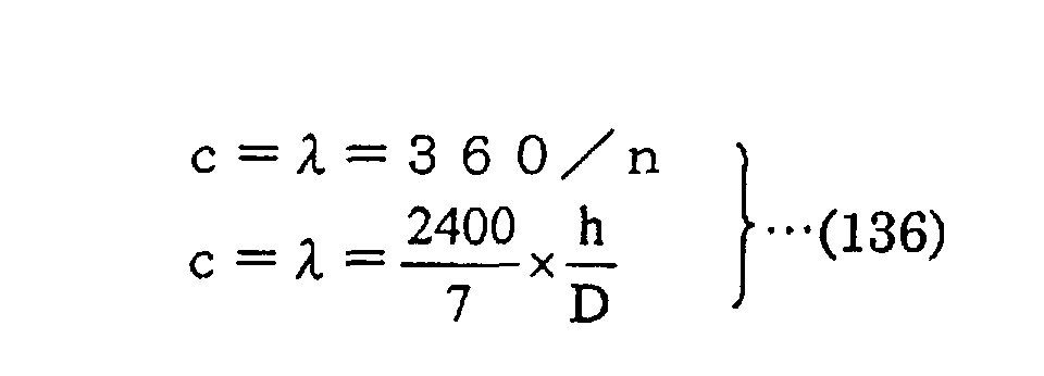
  • the third equation (the bottom equation) in equation 141 below is important to determine a design manual.
  • a fluid feeding device 7 shown in Fig. 18 includes a blower 9 constituted by propeller fan 1 in Embodiment 21 and a drive motor 8, and fluid is fed out by blower 9.
  • Fluid feeding device 7 in the present embodiment is an outdoor unit 10 of an air conditioner.
  • Outdoor unit 10 includes an outdoor heat exchanger 11, and efficiently exchanges heat by blower 9 described above.
  • blower 9 is installed in outdoor unit 10 by a motor angle 12, and a supply opening 13 of outdoor unit 10 is formed to be a bell mouth 14 as shown in Fig. 19.
  • blower 9 having a ring splasher 15 installed on the periphery of propeller fan 1, as shown in Fig. 20, may also be provided at fluid feeding device 7.
  • fluid feeding device 7 in an air conditioner of a type having an indoor unit and an outdoor unit formed in one piece to be attached to a window or the like, drain water may be splashed up and sprayed on outdoor heat exchanger 11, to further increase the efficiency.
  • Outdoor unit 10 in the present embodiment is a quiet outdoor unit with reduced noise, since propeller fan 1 in Embodiment 21 is included therein. Moreover, propeller fan 1 has an increased fan efficiency, so that an efficient outdoor unit realizing energy-saving can be attained. Furthermore, propeller fan 1 can be reduced in weight so that outdoor unit 10 can also achieve weight saving. It is presumed that propeller fans in other embodiments may also attain similar results.
  • Fig. 21 shows a front view of propeller fan 1 according to the present invention.
  • Propeller fan 1 of the present invention is molded in one piece by synthetic resin such as, for example, AS resin with glass fiber.
  • the diameter D 400 mm
  • the height in the axial direction (z direction) h 140 mm
  • the number of blades n 3
  • three blades 3 are radially and integrally provided on the periphery of boss portion 2.
  • the shape of the surface of blade 3 of propeller fan 1 is obtained based on a base shape defined by specific coordinate values.
  • the shape of a curved surface which is defined by coordinate values obtained by transforming the coordinate values in the base shape in the r, ⁇ and z directions using prescribed transformation formulas respectively, is determined as the shape of the surface of blade 3 of propeller fan 1.
  • the base shape of the present invention is typically defined by the coordinate values indicated in Table 202 described earlier.
  • the shape which is defined by coordinate values obtained by uniformly transforming the coordinate values indicated in Table 202 by e.g. multiplying the coordinate values with prescribed coefficients, should also be interpreted as equivalent to the base shape of the present invention.
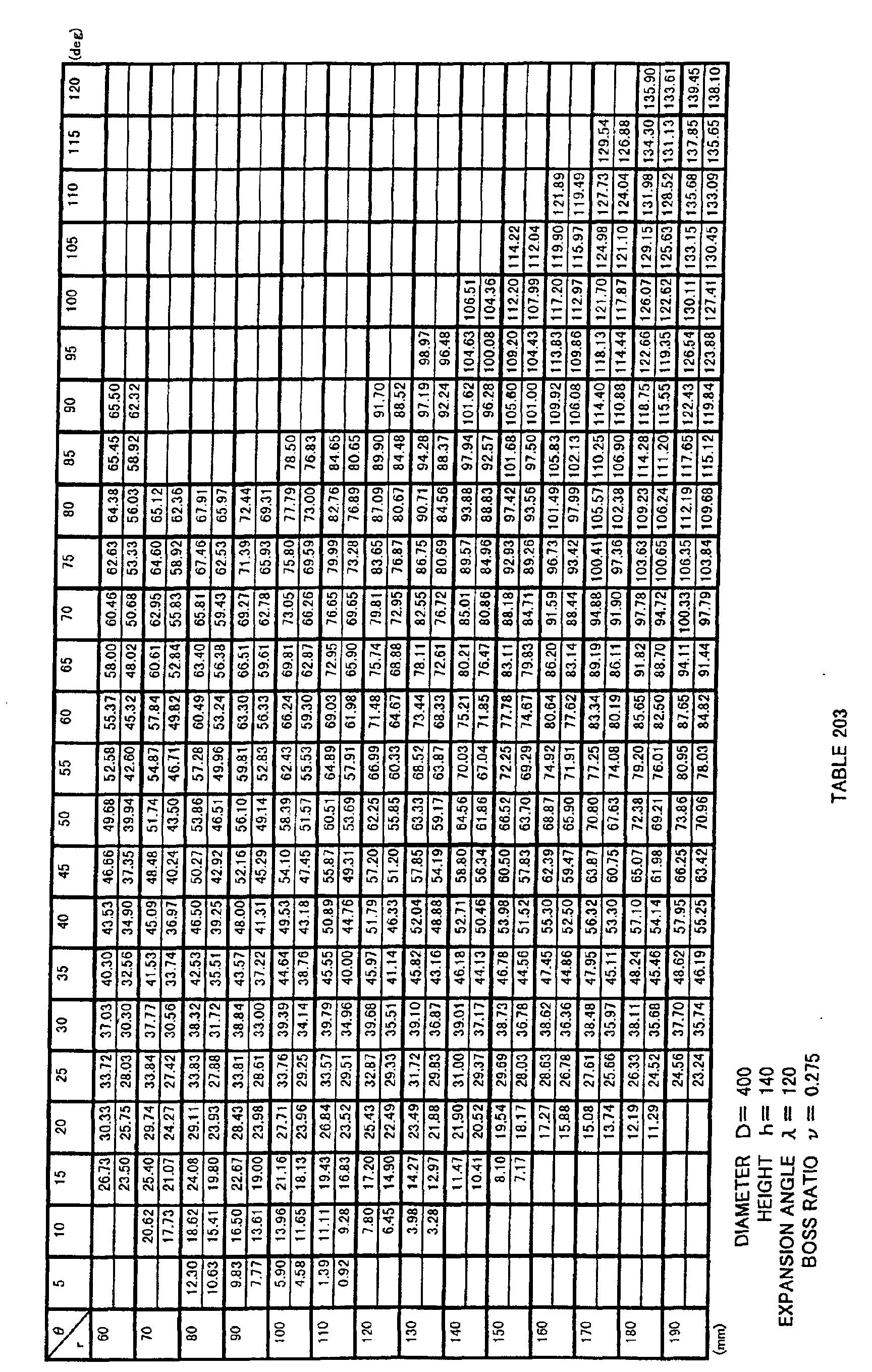
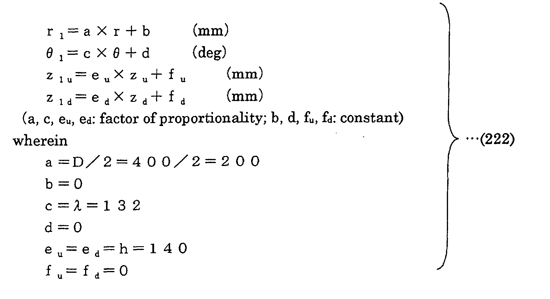
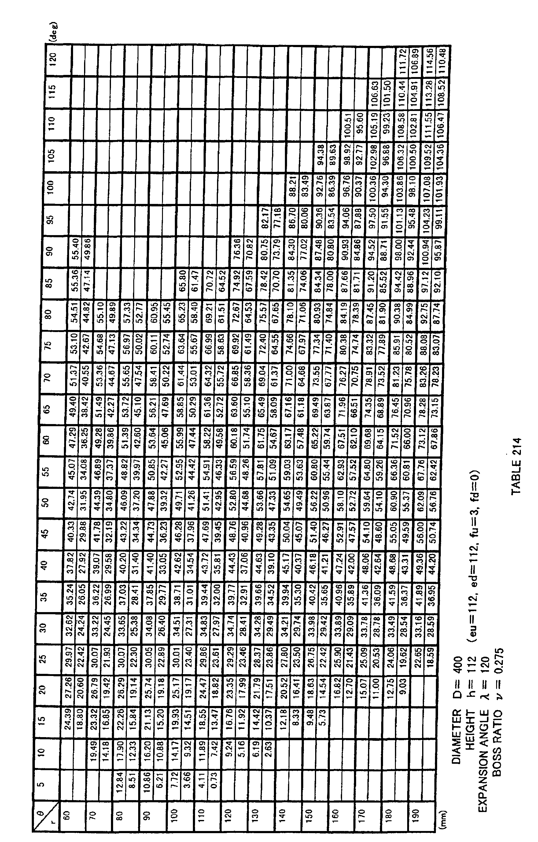
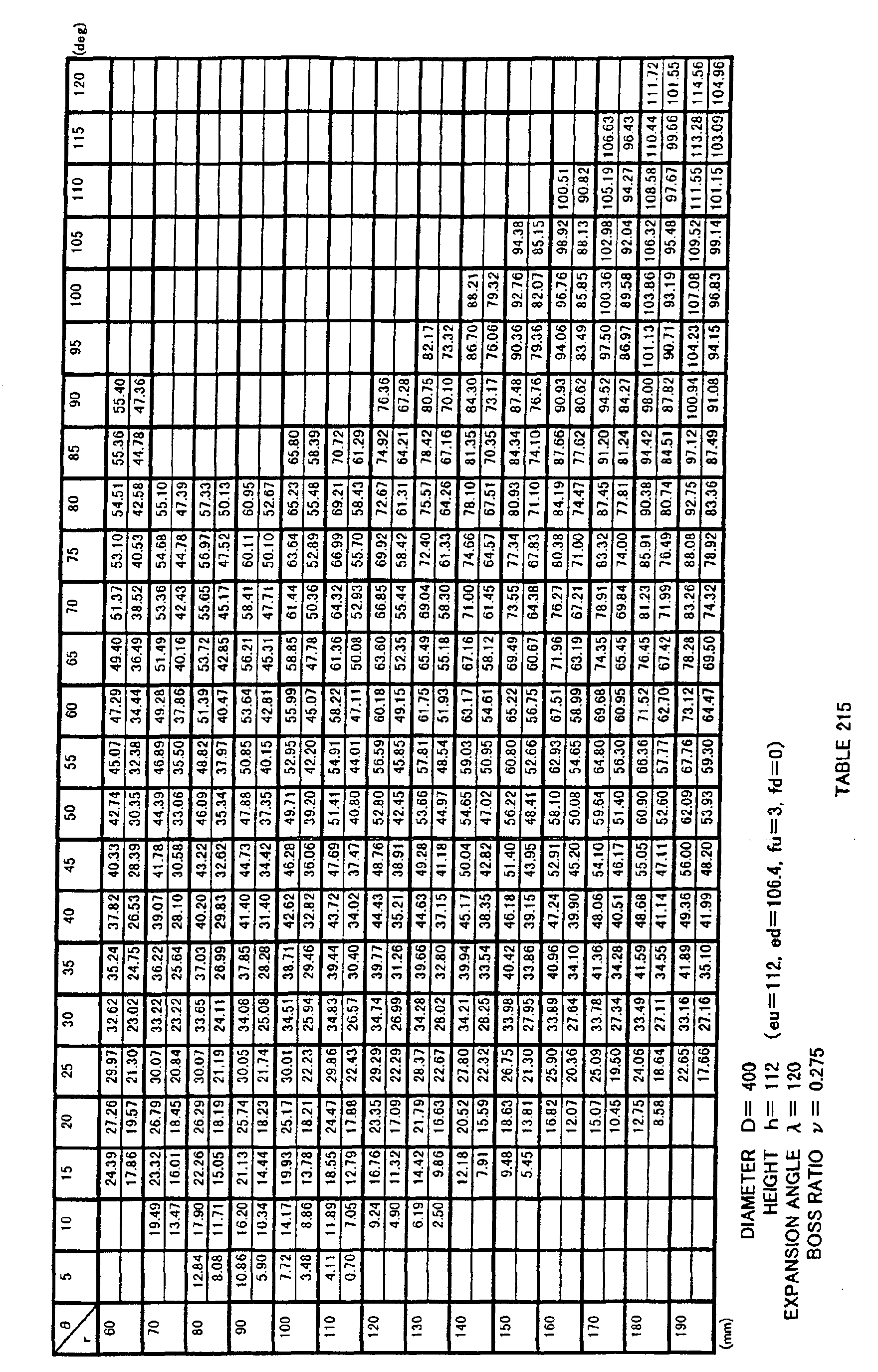
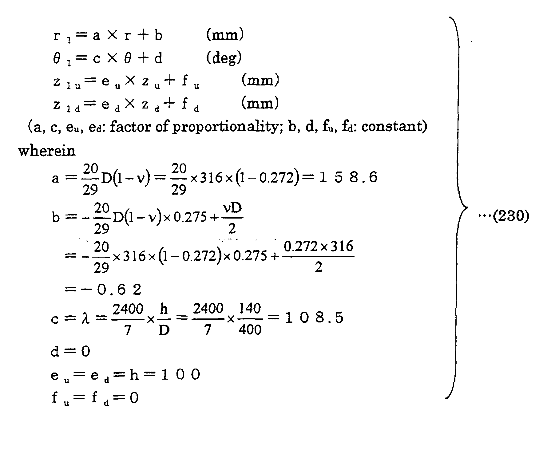
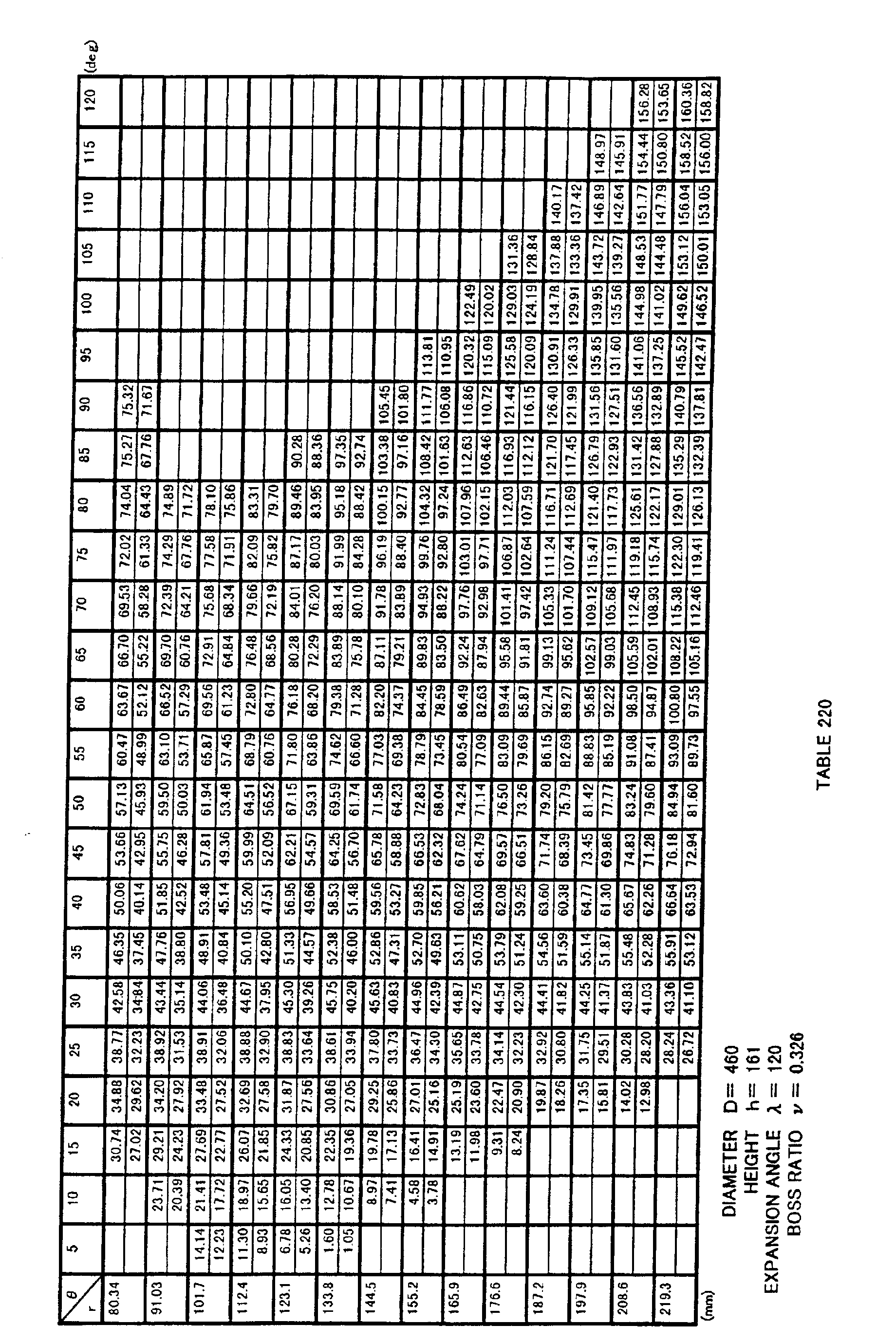
  • coordinates (r 1 , ⁇ 1 , z 1u ) of a surface on a negative pressure side of blade 3 and coordinates (r 1 , ⁇ 1 , z 1d ) of a surface on a positive pressure side of blade 3 are coordinate values obtained by transforming non-dimensionally expressed three-dimensional coordinate values indicated in Table 202 using a transformation formula 213 below, and the surface on the negative pressure side and the surface on the positive pressure side are configured by curved surfaces defined by the obtained coordinate values, i.e. a curved surface specified by coordinate values indicated in Table 203.
  • the curved surface may also be specified by coordinate values within the range of ⁇ 5 % of each coordinate value.
  • Fig. 21 shows a cylindrical coordinate system of r and ⁇ by dashed lines. It is noted that, though the z axis is not shown in Fig. 21, the z axis is a line passing the center of rotation 0 of boss portion 2 of propeller fan 1 in Fig. 21 and perpendicular to the plane of the drawing (that is, a line overlapping with a core of the rotation axis of propeller fan 1).
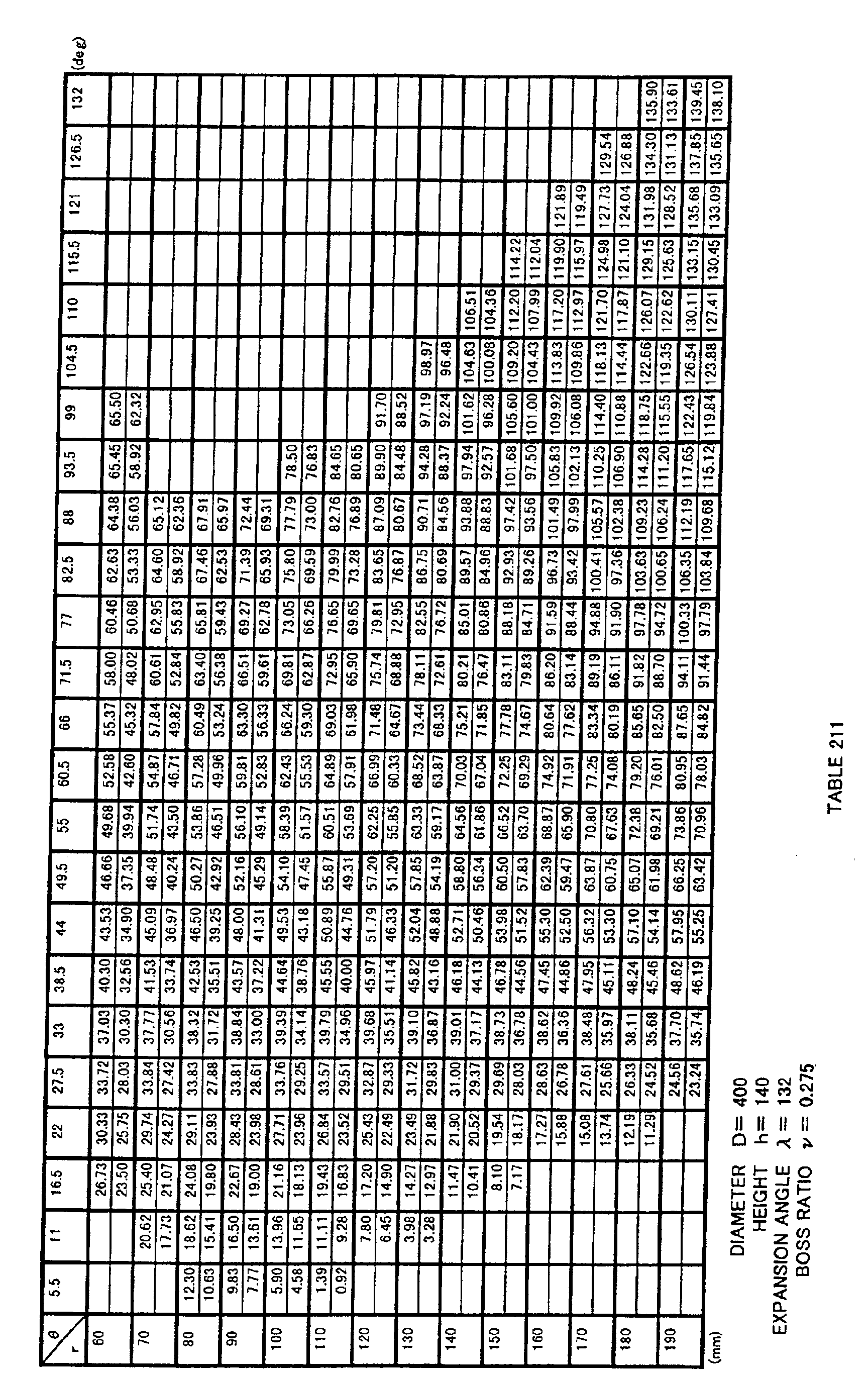
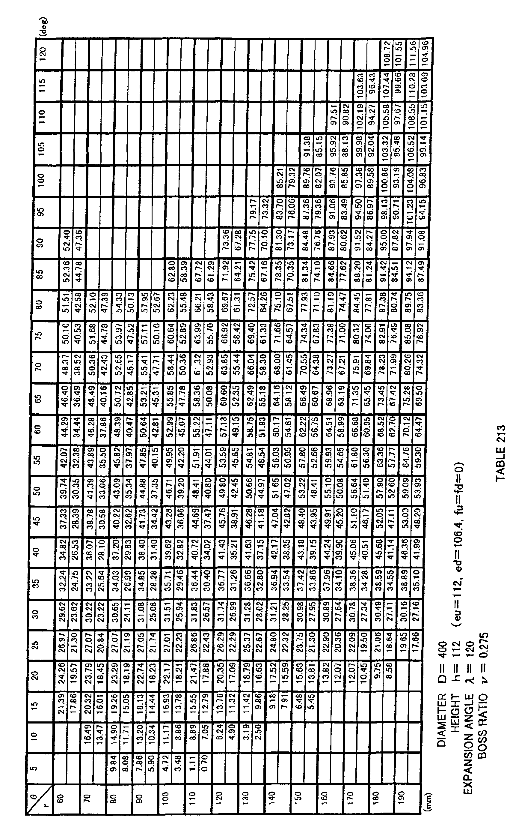
  • Fig. 21 for blade 3 of propeller fan 1, lines are drawn in the r direction that divide the blade at intervals of every 10 mm in the range between 60 mm and 190 mm, and lines are drawn that divide the blade in the ⁇ direction at intervals of every 5 deg in the range between 0 deg and 125 deg, a coordinate value of z at each crossing point being indicated in Table 203.
  • the top of each column indicates a value on the negative pressure surface side (suction side) of the propeller fan, whereas the bottom of each column indicates a value on the positive pressure surface side (blowing side) thereof.
  • propeller fan 1 of the present invention may be molded in one piece by synthetic resin such as ABS (acrylonitrile-butadiene-styrene) resin or polypropylene (PP), or may be integrally molded in one piece by synthetic resin having an increased intensity by including mica or the like, or may be non-integrally molded.
  • synthetic resin such as ABS (acrylonitrile-butadiene-styrene) resin or polypropylene (PP)
  • PP polypropylene
  • Fig. 27 shows an example of a propeller-fan-molding die 4 for forming propeller fan 1 shown in Fig. 21.
  • Die 4 is for molding propeller fan 1 by synthetic resin, and has a fixed-side die 5 and a movable-side die 6, as shown in Fig. 27.
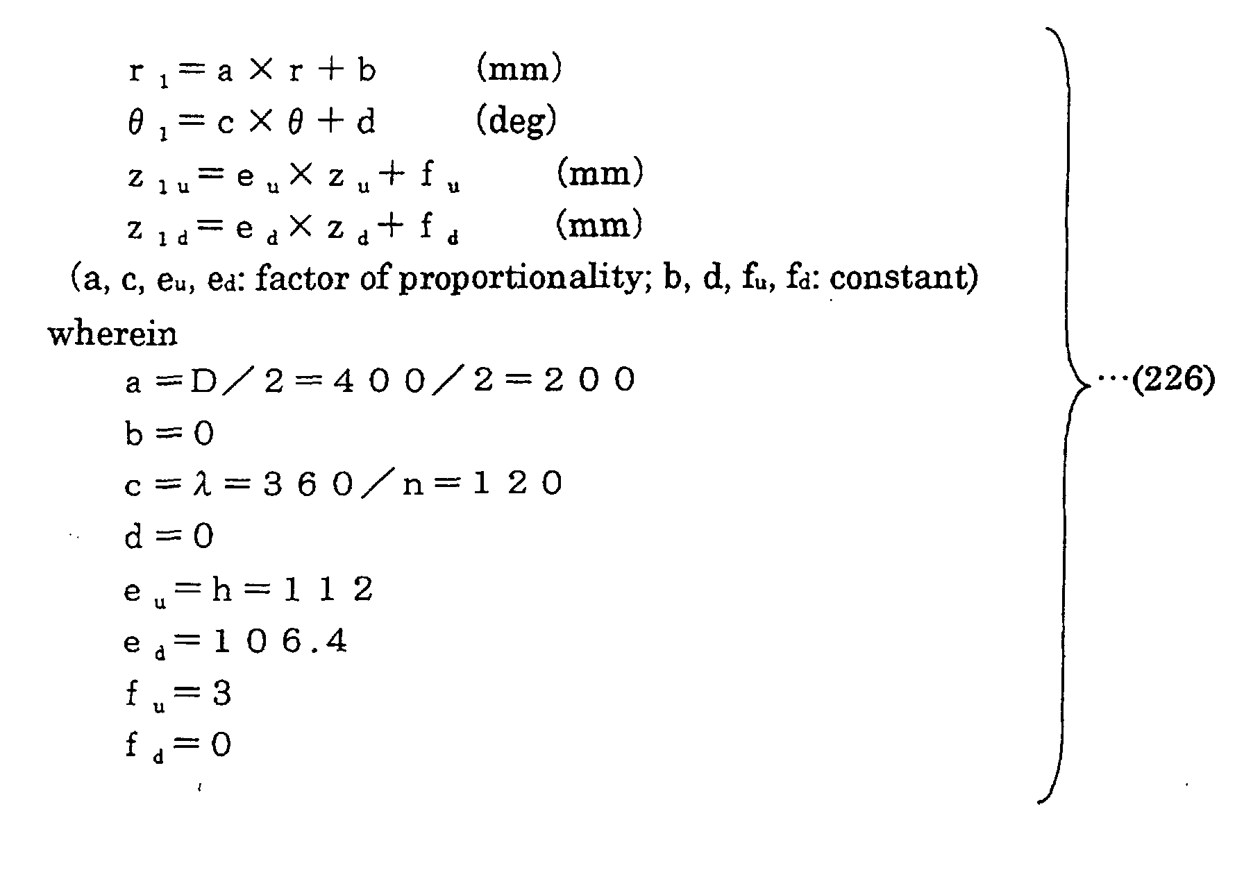
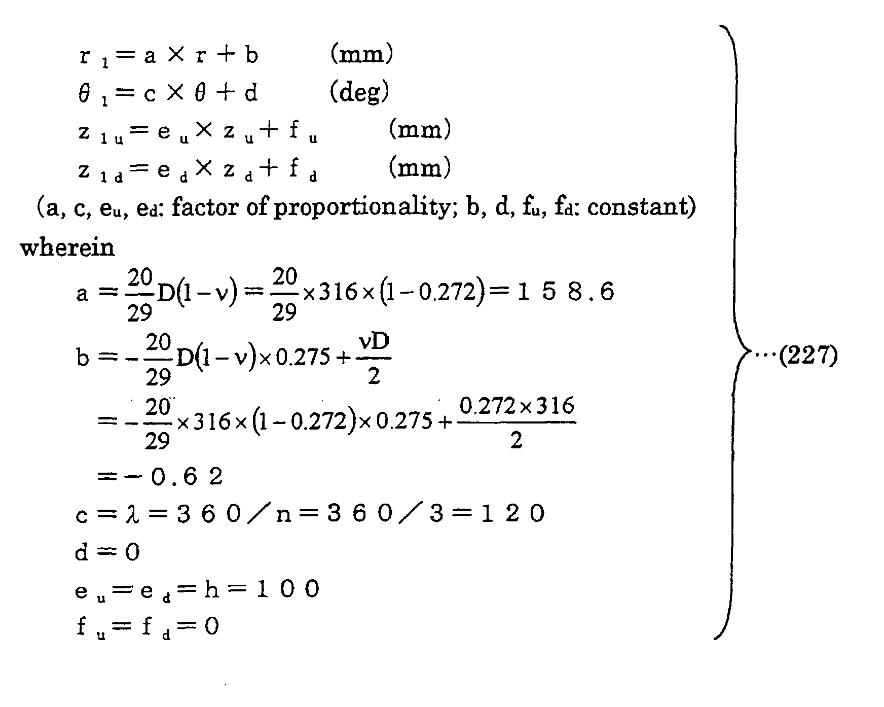
  • Coordinates (r 1 , ⁇ 1 , z 1u ) on the die surface of a portion forming the surface of blade 3 in fixed-side die 5 described above and coordinates (r 1 , ⁇ 1 , z 1d ) on the die surface of a portion forming the surface of blade 3 in movable-side die 6 are obtained by transforming non-dimensionally expressed three-dimensional coordinate values indicated in Table 202 using a transformation formula 214 below.
  • fixed-side die 5 and movable-side die 6 have curved portions respectively specified by coordinate values indicated in Table 203. It is noted that, in this case also, each curved surface may be specified by coordinate values within the range of ⁇ 5 % of each coordinate value.
  • the dimension of the curved surface of the die may be determined in consideration of mold shrinkage.
  • the coordinate data above may be corrected in consideration of the mold shrinkage, warping and deformation, to form molding die 4, such that propeller fan 1 having blade 3 with a three-dimensional curved surface specified by coordinate values within the range of ⁇ 5 % of three-dimensional coordinate values indicated in Table 203 above is formed after the mold shrinkage, and these are encompassed by the molding die of the present invention.
  • die 4 for molding the propeller fan in the present embodiment includes the negative pressure side surface of propeller fan 1 formed by fixed-side die 5 and a positive pressure side surface of propeller fan formed by movable-side die 6 as shown in Fig. 27, it may be possible to form the positive pressure side surface of propeller fan 1 by fixed-side die 5 and the negative pressure side surface of propeller fan 1 by movable-side die 6.
  • Figs. 22 and 23 each shows a perspective view of propeller fan 1 in the present Embodiment 41.
  • Fig. 24 is a front view of a propeller fan in Comparison Example 7
  • Figs. 25 and 26 are perspective views of the propeller fan in Comparison Example 7.
  • a boss portion is denoted by 2 in the drawings. Note that r, ⁇ , z are set as in Embodiment 41.
  • Each of the propeller fans as in Embodiments 41 to 60 and those in Comparison Examples 7 to 9 is attached to an outdoor unit of an air conditioner, and airflow, power consumption and noise are measured.
  • each fan in Embodiments 41 to 53 and in Comparison Example 7 having the fan diameter of ⁇ 400 was driven by a DC motor using an outdoor unit with a refrigeration capacity of a 28 kW class.
  • the results are shown in Table 226 below.
  • each fan in Embodiments 58 to 60 and in Comparison Example 9 having the fan diameter of ⁇ 460 was driven by an AC motor using a multiple-type large outdoor unit.
  • the results are shown in Table 228 below.
  • weight was reduced by approximately 20 % for each propeller fan shown in Embodiments 41 to 53 compared to Comparison Example 7, without degradation of its performance, and thus the cost was also reduced.
  • the 20% of weight saving can realize reduction of startup torque occurred at startup of the blower and also reduction of cost for the drive motor. It is noted that deformation of a blade, which is a problem common to a thin blade, was largely reduced compared to that in Comparison Example 7.
  • weight was reduced by 17 % for each propeller fan shown in Embodiments 58 to 60 compared to Comparison Example 9, without degradation of its performance, and thus the cost was also reduced.
  • 17% of weight saving can realize reduction of startup torque occurred at startup of the blower and also reduction of cost for the drive motor. It is noted that the deformation of a blade that is a problem common to a thin blade was largely reduced compared to that in Comparison Example 7.
  • the ratio of h/D is smaller, i.e., the thickness of a wing is thinner, than that in Embodiment 41.
  • the wing is largely deformed at rotation of the fan due to the centrifugal force applied on the wing (blade), reducing the height of the wing, and therefore degradation occurs in terms of efficiency and noise.
  • Embodiments 56 and 57 in Table 227 above are compared with each other, Embodiment 57 was superior to Embodiment 56.
  • Embodiment 58 was superior to Embodiments 59 and 60.
  • the third equation (the bottom equation) in equation 241 below is important to determine a design manual.
  • a fluid feeding device 7 shown in Fig. 28 includes a blower 9 constituted by propeller fan 1 in Embodiment 41 and a drive motor 8, and fluid is fed out by blower 9.
  • Fluid feeding device 7 in the present embodiment is an outdoor unit 10 of an air conditioner.
  • Outdoor unit 10 includes an outdoor heat exchanger 11, and efficiently exchanges heat by blower 9 described above.
  • blower 9 is installed in outdoor unit 10 by a motor angle 12, and a supply opening 13 of outdoor unit 10 is formed to be a bell mouth 14 as shown in Fig. 29.
  • blower 9 having a ring splasher 15 installed on the periphery of propeller fan 1, as shown in Fig. 30, may also be provided at fluid feeding device 7.
  • fluid feeding device 7 in an air conditioner of a type having an indoor unit and an outdoor unit formed in one piece to be attached to a window or the like, drain water may be splashed up and sprayed on outdoor heat exchanger 11, to further increase the efficiency.
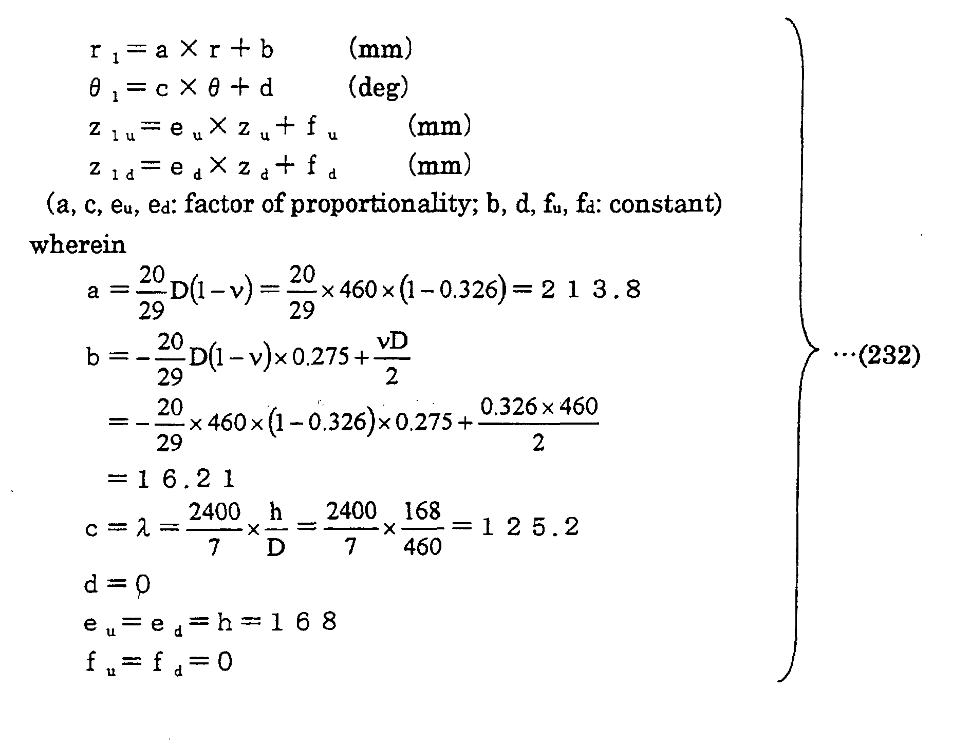
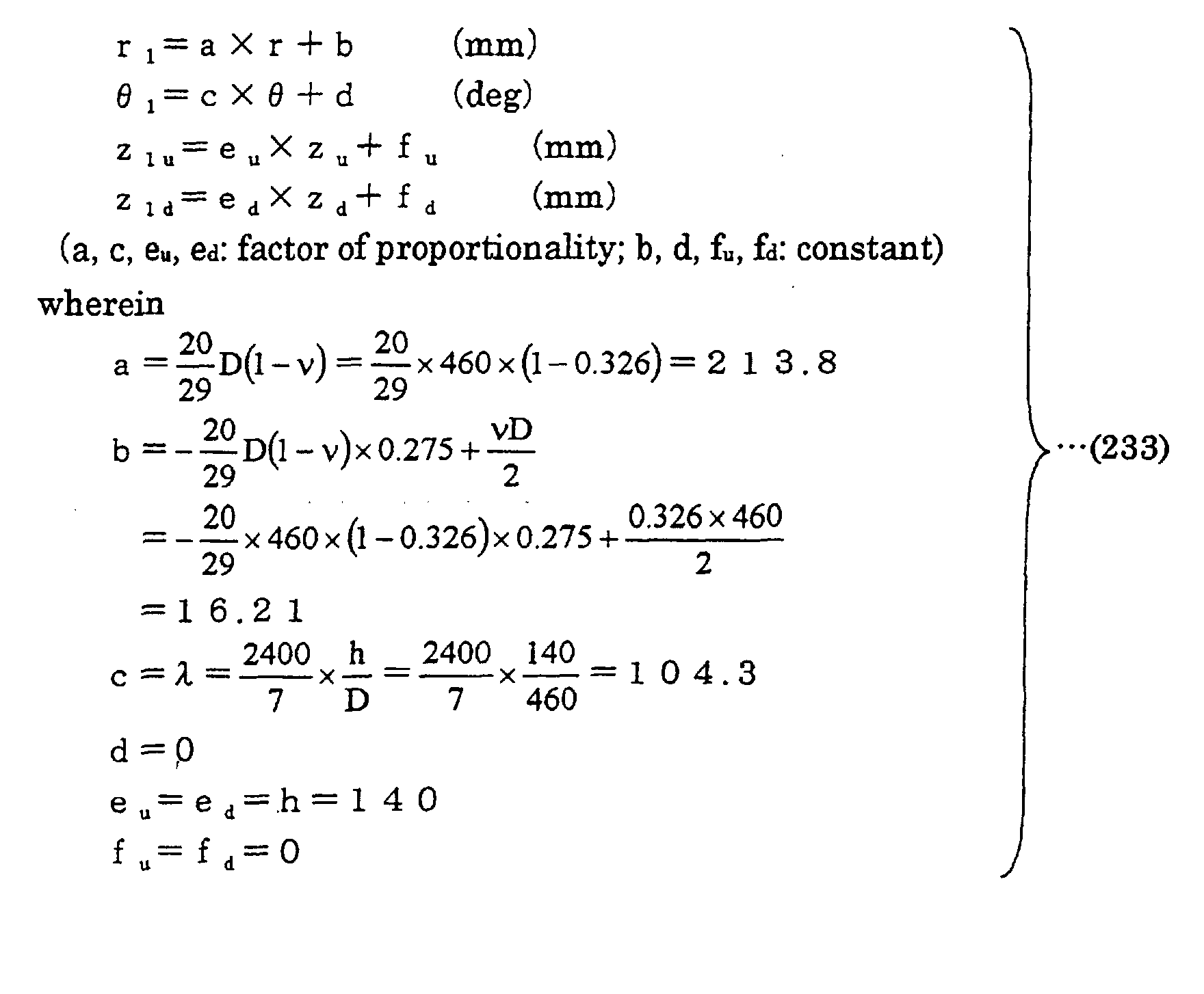
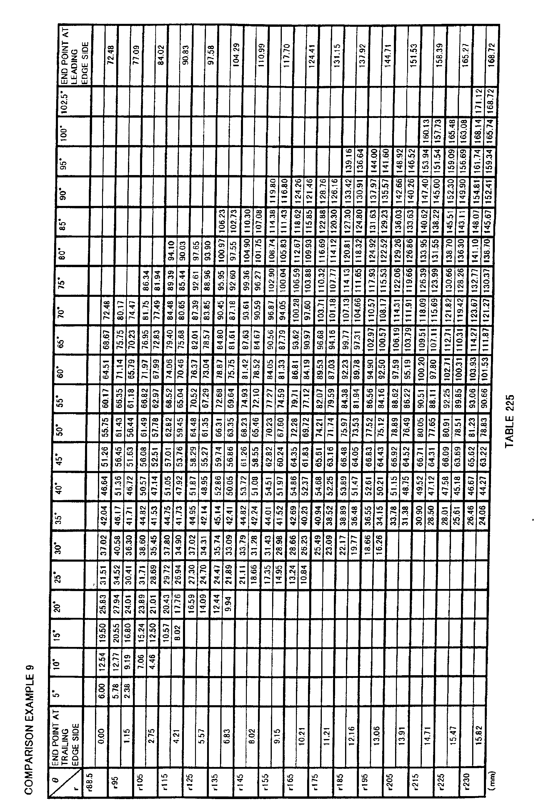
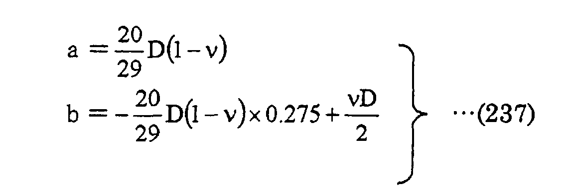
  • Outdoor unit 10 in the present embodiment is a quiet outdoor unit with reduced noise, since propeller fan 1 in Embodiment 41 is included therein. Moreover, propeller fan 1 has an improved fan efficiency, so that an efficient outdoor unit realizing energy-saving can be attained. Furthermore, propeller fan 1 can be reduced in weight so that outdoor unit 10 can also achieve weight saving. In addition, propeller fan 1 has an increased breaking strength at rotation, so that the number of rotations of propeller fan 1 can be increased resulting in enhanced performance of outdoor unit 10. It is presumed that propeller fans in other embodiments may also attain similar results.
  • a base shape defined by three-dimensional coordinate values indicated in Tables 1 and 2 are appropriately modified to obtain a shape of the surface of a blade. More specifically, a curved surface, which is defined by coordinate values obtained by transforming three-dimensional coordinate values indicated in Tables 1 and 2 in r, ⁇ and z directions using prescribed transformation formulas, is determined as the shape of the surface of the blade of the propeller fan.
  • the propeller fan can be made higher in efficiency and lower in noise, independent of the diameter, height and the like of the propeller fan, as indicated in Tables 48 to 50. Therefore, according to the propeller fan in the present invention, a larger volume of air flow can be attained compared to the conventional example at the same power consumption and the same noise level.
  • the surface of a portion forming the surface of a blade is configured by a curved surface obtained by enlarging or reducing the base shape in at least one of r, ⁇ and z directions, so that the propeller fan according to the present invention described above can be molded.
  • a propeller fan When the base shape defined by three-dimensional coordinate values indicated in Tables 1 and 2 is transformed by a transformation formula (1), a propeller fan can be improved in efficiency and can be reduced in noise, independent of the diameter, height and the like of the propeller fan, as indicated in Table 48 (e.g., see Embodiment 1). Therefore, any value may be selected for the diameter, height, number of blades and expansion angle of a blade, to obtain a propeller fan with high efficiency and low noise.
  • the surface of a portion forming the surface of a blade is configured by a curved surface defined by coordinate values obtained by transforming three-dimensional coordinate values indicated in Tables 1 and 2 using transformation formula (1), so that the propeller fan of the present invention described above can be molded.
  • the propeller fan can be improved in efficiency and reduced in noise, independent of the diameter, height and the like of the propeller fan, as indicated in Table 48 (e.g., see Embodiment 2). Moreover, in addition to achievement of high efficiency and low noise, a propeller fan having n blades, which do not overlap with one another and thus can hold down the cost of a molding die, can easily be obtained.
  • the surface of a portion forming the surface of the blade is configured by a curved surface defined by coordinate values obtained by transforming three-dimensional coordinate values indicated in Tables 1 and 2 using transformation formula (2), so that the propeller fan of the present invention described above can be molded.
  • the propeller fan can be improved in efficiency and reduced in noise, independent of the diameter, height and the number of blades of the propeller fan, as indicated in Table 48 (e.g., see Embodiment 7).
  • the surface of a portion forming the surface of the blade is configured by a curved surface defined by coordinate values obtained by transforming three-dimensional coordinate values indicated in Tables 1 and 2 using transformation formula (3), so that the propeller fan of the present invention described above can be molded.
  • the propeller fan can be improved in efficiency and reduced in noise, independent of the diameter, height, number of blades, boss diameter and boss ratio of the propeller fan, as indicated in Table 48 (e.g., see Embodiment 10).
  • the surface of a portion forming the surface of the blade is configured by a curved surface defined by coordinate values obtained by transforming three-dimensional coordinate values indicated in Tables 1 and 2 using transformation formula (4), so that the propeller fan of the present invention described above can be molded.
  • the propeller fan can be improved in efficiency and reduced in noise, independent of the diameter, height, number of blades, and boss ratio of the propeller fan, as indicated in Table 49 (e.g., see Embodiment 14).
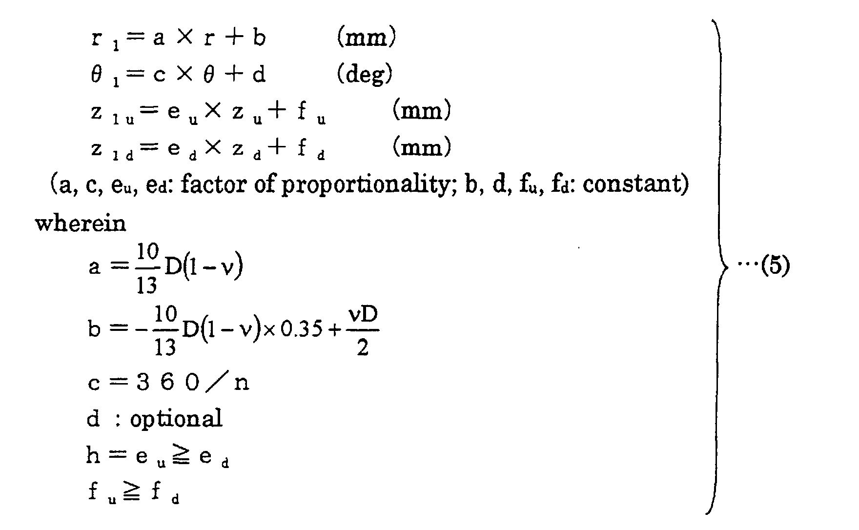
  • the surface of a portion forming the surface of the blade is configured by a curved surface defined by coordinate values obtained by transforming three-dimensional coordinate values indicated in Tables 1 and 2 using transformation formula (5), so that the propeller fan of the present invention described above can be molded.
  • the propeller fan can be improved in efficiency and reduced in noise, independent of the diameter, height, number of blades, and boss ratio of the propeller fan, as indicated in Table 49 (e.g., see Embodiment 17).
  • the surface of a portion forming the surface of the blade is configured by a curved surface defined by coordinate values obtained by transforming three-dimensional coordinate values indicated in Tables 1 and 2 using transformation formula (6), so that the propeller fan of the present invention described above can be molded.
  • a fluid feeding device includes a blower having the propeller fan according to any one of the above, so that good efficiency and energy saving can be achieved, resulting in a device with low noise.
  • the base shape defined by three-dimensional coordinate values indicated in Table 101 is appropriately modified to obtain the shape of the surface of the blade.
  • a curved surface which is defined by coordinate values obtained by transforming three-dimensional coordinate values indicated in Table 101 in r, ⁇ and z directions using prescribed transformation formulas respectively, is determined as the shape of the surface of the blade of the propeller fan.
  • the surface of a portion forming the surface of a blade is configured by a curved surface obtained by enlarging or reducing the base shape in at least one of r, ⁇ and z directions, so that the propeller fan according to the present invention described above can be molded.
  • a propeller fan When the base shape defined by three-dimensional coordinate values indicated in Table 101 is transformed by a transformation formula (101), a propeller fan can be improved in efficiency and can be reduced in noise, independent of the diameter, height and the like of the propeller fan, as indicated in Table 126 (e.g., see Embodiment 21). Further, the weight and cost can be reduced. Therefore, any value may be selected for the diameter, height, number of blades and expansion angle of a blade, to obtain a propeller fan with light weight, high efficiency and low noise at a low cost.
  • the surface of a portion forming the surface of a blade is configured by a curved surface defined by coordinate values obtained by transforming three-dimensional coordinate values indicated in Table 101 using transformation formula (101), so that the propeller fan of the present invention described above can be molded.
  • the propeller fan can be improved in efficiency and reduced in noise, independent of the diameter, height and the like of the propeller fan, as indicated in Table 126 (e.g., see Embodiment 2).
  • a propeller fan having n blades which do not overlap with one another and thus can hold down the cost of a molding die, can easily be obtained.
  • the surface of a portion forming the surface of the blade is configured by a curved surface defined by coordinate values obtained by transforming three-dimensional coordinate values indicated in Table 101 using transformation formula (102), so that the propeller fan of the present invention described above can be molded.
  • the propeller fan can be improved in efficiency and can be reduced in weight and cost, and can also be reduced in noise, independent of the diameter, height and the number of blades of the propeller fan, as indicated in Table 126 (e.g., see Embodiment 27).
  • the surface of a portion forming the surface of the blade is configured by a curved surface defined by coordinate values obtained by transforming three-dimensional coordinate values indicated in Table 101 using transformation formula (103), so that the propeller fan of the present invention described above can be molded.
  • the propeller fan can be improved in efficiency and reduced in weight and cost, and can also be reduced in noise, independent of the diameter, height, number of blades, and boss ratio of the propeller fan, as indicated in Table 126 (e.g., see Embodiment 30).
  • the surface of a portion forming the surface of the blade is configured by a curved surface defined by coordinate values obtained by transforming three-dimensional coordinate values indicated in Table 101 using transformation formula (104), so that the propeller fan of the present invention described above can be molded.
  • the propeller fan can be improved in efficiency and reduced in weight and cost, and can also be reduced in noise, independent of the diameter, height, number of blades, and boss ratio of the propeller fan, as indicated in Table 127 (e.g., see Embodiment 34).
  • the surface of a portion forming the surface of the blade is configured by a curved surface defined by coordinate values obtained by transforming three-dimensional coordinate values indicated in Table 101 using transformation formula (105), so that the propeller fan of the present invention described above can be molded.
  • the propeller fan can be improved in efficiency and reduced in weight and cost, and can also be reduced in noise, independent of the diameter, height, number of blades, and boss ratio of the propeller fan, as indicated in Table 127 (e.g., see Embodiment 37).
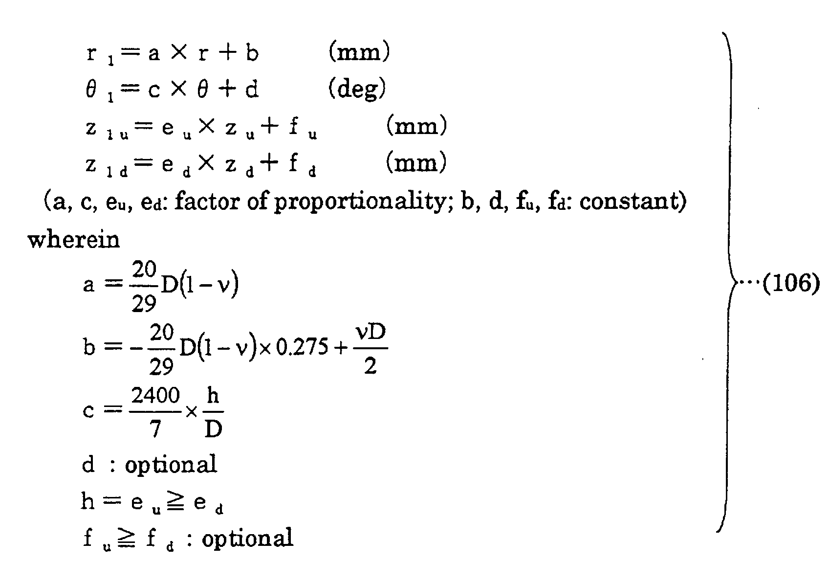
  • the surface of a portion forming the surface of the blade is configured by a curved surface defined by coordinate values obtained by transforming three-dimensional coordinate values indicated in Table 101 using transformation formula (106), so that the propeller fan of the present invention described above can be molded.
  • a fluid feeding device includes a blower having the propeller fan according to any one of the above, so that good efficiency and energy saving can be achieved, resulting in a device with low noise and reduced weight.
  • the base shape defined by three-dimensional coordinate values indicated in Table 201 is appropriately modified to obtain the shape of the surface of the blade.
  • a curved surface which is defined by coordinate values obtained by transforming three-dimensional coordinate values indicated in Table 201 in r, ⁇ and z directions using prescribed transformation formulas respectively, is determined as the shape of the surface of a blade of the propeller fan.
  • the propeller fan can also be reduced in weight and thus the cost can be lowered. Therefore, according to the propeller fan in the present invention, a larger volume of air flow can be attained compared to the conventional example at the same power consumption and the same noise level, and also the weight and cost can be reduced. Furthermore, it is superior in terms of deformation due to the centrifugal force and in terms of strength against breaking at rotation, and thus there is no need to partially increase the thickness of a root of a blade portion.
  • the surface of a portion forming the surface of a blade is configured by a curved surface obtained by enlarging or reducing the base shape in at least one of r, ⁇ and z directions, so that the propeller fan according to the present invention described above can be molded.
  • a propeller fan When the base shape defined by three-dimensional coordinate values indicated in Table 201 is transformed by a transformation formula (201), a propeller fan can be improved in efficiency and can be reduced in noise, independent of the diameter, height and the like of the propeller fan, as indicated in Table 226 (e.g., see Embodiment 1). Further, the weight and cost can also be reduced. In addition, the strength of the propeller fan can be increased without the thickness of the root of the blade portion being partially increased. Therefore, any value may be selected for the diameter, height, number of blades and expansion angle of a blade, to obtain a propeller fan with light weight, high strength, high efficiency and low noise.
  • the surface of a portion forming the surface of a blade is configured by a curved surface defined by coordinate values obtained by transforming three-dimensional coordinate values indicated in Table 201 using transformation formula (201), so that the propeller fan of the present invention described above can be molded.
  • the propeller fan can be improved in efficiency and reduced in noise, independent of the diameter, height and the like of the propeller fan, as indicated in Table 226 (e.g., see Embodiment 42). Moreover, in addition to achievement of high efficiency, low noise, light weight, low cost and increased strength, a propeller fan having n blades, which do not overlap with one another and thus can hold down the cost of the die, can easily be obtained.
  • the surface of a portion forming the surface of the blade is configured by a curved surface defined by coordinate values obtained by transforming three-dimensional coordinate values indicated in Table 201 using transformation formula (202), so that the propeller fan of the present invention described above can be molded.
  • the propeller fan can be improved in efficiency, reduced in weight and cost, and increased in strength, and can also be reduced in noise, independent of the diameter, height and the number of blades of the propeller fan, as indicated in Table 226 (e.g., see Embodiment 47).
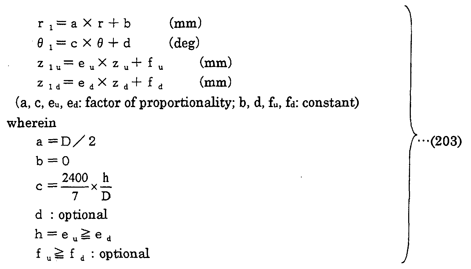
  • the surface of a portion forming the surface of the blade is configured by a curved surface defined by coordinate values obtained by transforming three-dimensional coordinate values indicated in Table 201 using transformation formula (203), so that the propeller fan of the present invention described above can be molded.
  • the propeller fan can be improved in efficiency, reduced in weight and cost, and increased in strength, and can also be reduced in noise, independent of the diameter, height, number of blades, boss diameter and boss ratio of the propeller fan, as indicated in Table 226 (e.g., see Embodiment 50).
  • the surface of a portion forming the surface of the blade is configured by a curved surface defined by coordinate values obtained by transforming three-dimensional coordinate values indicated in Table 201 using transformation formula (204), so that the propeller fan of the present invention described above can be molded.
  • the propeller fan can be improved in efficiency, reduced in weight and cost, and increased in strength, and can also be reduced in noise, independent of the diameter, height, number of blades, and boss ratio of the propeller fan, as indicated in Table 227 (e.g., see Embodiment 54).
  • the surface of a portion forming the surface of the blade is configured by a curved surface defined by coordinate values obtained by transforming three-dimensional coordinate values indicated in Table 201 using transformation formula (205), so that the propeller fan of the present invention described above can be molded.
  • the propeller fan can be improved in efficiency, reduced in weight and cost, and increased in strength, and can also be reduced in noise, independent of the diameter, height, number of blades, and boss ratio of the propeller fan, as indicated in Table 227 (e.g., see Embodiment 57).
  • the surface of a portion forming the surface of the blade is configured by a curved surface defined by coordinate values obtained by transforming three-dimensional coordinate values indicated in Table 201 using transformation formula (206), so that the propeller fan of the present invention described above can be molded.
  • a fluid feeding device includes a blower having the propeller fan according to any one of the above, so that good efficiency and energy saving can be achieved, resulting in a device with low noise, light weight and increased strength.
  • the present invention may be applied to a propeller fan, a die for molding the propeller fan and a fluid feeding device.

Landscapes

  • Engineering & Computer Science (AREA)
  • Mechanical Engineering (AREA)
  • General Engineering & Computer Science (AREA)
  • Structures Of Non-Positive Displacement Pumps (AREA)
  • Moulds For Moulding Plastics Or The Like (AREA)

Abstract

In a propeller fan (1) according to the present invention, when coordinates in a cylindrical coordinate system having a z axis as a rotation axis of the propeller fan (1) are (r, , z), a curved shape defined by prescribed r,  and z coordinate values is determined as a base shape of a surface of a blade (3) of the propeller fan (1), and the surface of the blade (3) of the propeller fan (1) is configured by a curved surface obtained by enlarging or reducing the base shape in at least one of r,  and z directions.

Description
Technical Field
The present invention relates to a propeller fan constituting a blower together with a drive motor; a molding die for the propeller fan; and a fluid feeding device provided with the blower, such as an outside unit of an air conditioner, an air cleaner, a humidifier, a dehumidifier, an electric fan, a fan heater, a cooling device, and a ventilator.
Background Art
Conventionally, a propeller fan is used in a blower or a cooler. For example, the outside unit of an air conditioner is provided with a propeller fan for cooling.
The propeller fan for cooling has conventionally had a problem such that it produces high noise at rotation and thus is inefficient. Airflow may be reduced to lower the noise, which then presents a problem of insufficient achievement of cooling effect.
Moreover, there also was a problem of heavy weight, increasing not only the cost of manufacturing, but also the load applied to a drive motor at startup of the blower. Thus, the weight of the propeller fan may be made lighter, simply, by reducing the thickness of a blade. However, when the thickness of the blade is simply reduced, flow tends to separate from the wing, causing a problem such that, in addition to that the noise is increased, the rigidity of the blade is lowered, a centrifugal force deforms the blade at the time of operation of the blower, which reduces the height of the fan in the axial direction, and thus the airflow is degraded.
Moreover, there also was a problem such that the strength in the vicinity of a root of the blade is lower, causing the fan to rotate at a high speed when windblast is applied to the blower, and the centrifugal force therefrom damages the fan. Here, as a simple manner, the thickness of the blade root may partially be increased in order to increase the strength of the propeller fan. However, when the thickness of a part of the blade root is simply increased, cooling time at fabrication is increased to a large degree, raising the cost.
Disclosure of the Invention
The present invention was made in view of the problems in the conventional example above, and an object of the present invention is to provide a propeller fan that can realize high airflow, high efficiency and low noise; a die for molding the same; and a fluid feeding device that can realize high airflow, high efficiency and low noise.
Another object of the present invention is to provide a propeller fan that can realize high airflow, high efficiency, low noise, light weight and low cost; a die for molding the same; and a fluid feeding device that can realize high airflow, high efficiency, low noise, light weight and low cost.
A further object of the present invention is to provide a propeller fan that can realize high airflow, high efficiency, low noise, light weight, low cost and increased strength; a die for molding the same; and a fluid feeding device that can realize high airflow, high efficiency, low noise, light weight, low cost and increased strength.
In a propeller fan according to the present invention, when coordinates in a cylindrical coordinate system having a z axis as a rotation axis of the propeller fan are (r, , z), a curved shape defined by a r coordinate value, a  coordinate value and a z coordinate value indicated in Tables 3 and 4 below is determined as a base shape of the blade surface of the propeller fan, and the surface of the blade of the propeller fan is configured by a curved surface obtained by enlarging or reducing the base shape in at least one of r,  and z directions.
Figure 00030001
Figure 00040001
In Tables 3 and 4, r indicates a non-dimensional r coordinate in the radial direction in the cylindrical coordinate system having the z axis as the rotation axis of the propeller fan,  indicates a non-dimensional  coordinate in the circumferential direction in the cylindrical coordinate system having the z axis as the rotation axis of the propeller fan, and z indicates a non-dimensional z coordinate in the axial direction (the direction of height) in the cylindrical coordinate system having the z axis as the rotation axis of the propeller fan.
Moreover, the top of each column (zu) indicates a coordinate value on a negative pressure side (suction side) of the propeller fan, whereas the bottom of each column (zd) indicates a coordinate value on a positive pressure side (blowing side) thereof. Table 3 indicates a non-dimensional coordinate value of z where r is within the range of 0.4 to 0.95 and where  is within the range of 0.042 to 1, and Table 4 indicates non-dimensional coordinate values of r,  and z at an outer edge portion of a blade. It is noted that the contents of Table 1 are the same as those in Table 3, and the contents of Table 2 are the same as those in Table 4.
Furthermore, values within the range of ± 5 % of the coordinate values calculated by transformation formulas of the present invention should be interpreted as included in a range of error and equivalent to the coordinate values of the present invention. This means that the shape defined by the coordinate values within the range of ± 5 % of the coordinate values calculated by transformation formulas of the present invention should be interpreted as included in a technical range of the present invention.
In addition, the shape defined by coordinate values obtained by uniformly transforming coordinate values indicated in Tables 1 to 4 should also be interpreted as included within the range of equivalent to the base shape of the present invention.
In a die for molding a propeller fan according to one aspect of the present invention, the surface of a portion forming the surface of a blade of the propeller fan is configured by a curved surface obtained by enlarging or reducing the base shape in at least one of r,  and z directions.
When the diameter of the propeller fan of the present invention is D, the height in the z direction which is the axial direction is h and the expansion angle of the blade is λ; r, , z coordinates (r1, 1, z1u) that define the surface on the suction side of the blade and r, , z coordinates (r1, 1, z1d) that define the surface on the blowing side of the blade are obtained by a transformation formula (7) below using three-dimensional coordinate values indicated in Tables 3 and 4. Then, the surface of the blade of the propeller fan is configured by a curved surface defined by the coordinates (r1, 1, z1u) and the coordinates (r1, 1, z1d).
It is noted that, in such a case that a transformation formula is used to change the form of the base shape, coordinate values obtained by uniformly transforming three-dimensional coordinate values indicated in Tables 3 and 4 may also be used to obtain the same result. Therefore, coordinate values calculated using such transformed coordinate values should also be interpreted as included in the technical range of the present invention, as long as the values can be calculated by respective transformation formulas below.
Figure 00060001
In a die for molding a propeller fan according to another aspect of the present invention, the surface of a portion forming the surface of a blade of the propeller fan is configured by a curved surface defined by r, , z coordinates (r1, 1, z1u) and r, , z coordinates (r1, 1, z1d) obtained by the transformation formula (7) above.
When the diameter of the propeller fan is D, the height in the z direction which is the axial direction is h and the number of blades is n; r, , z coordinates (r1, 1, z1u) that define the surface on the suction side of the blade and r, , z coordinates (r1, 1, z1d) that define the surface on the blowing side of the blade are obtained by a transformation formula (8) below using three-dimensional coordinate values indicated in Tables 3 and 4. Then, the surface of the blade of the propeller fan is configured by a curved surface defined by the coordinates (r1, 1, z1u) and the coordinates (r1, 1, z1d).
Figure 00070001
In a die for molding a propeller fan according to a further aspect of the present invention, the surface of a portion forming the surface of a blade of the propeller fan is configured by a curved surface defined by the coordinates (r1, 1, z1u) and the coordinates (r1, 1, z1d) obtained by the transformation formula (8) above.
When the diameter of the propeller fan is D and the height in the z direction which is the axial direction is h; r, , z coordinates (r1, 1, z1u) that define the surface on the suction side of the blade and r, , z coordinates (r1, 1, z1d) that define the surface on the blowing side of the blade are obtained by a transformation formula (9) below using three-dimensional coordinate values indicated in Tables 3 and 4. Then, the surface of the blade of the propeller fan is configured by a curved surface defined by the coordinates (r1, 1, z1u) and the coordinates (r1, 1 z1d).
Figure 00080001
In a die for molding a propeller fan according to yet another aspect of the present invention, the surface of a portion forming the surface of a blade of the propeller fan is configured by a curved surface defined by the coordinates (r1, 1, z1u) and the coordinates (r1, 1, z1d) obtained by the transformation formula (9) above.
When the diameter of the propeller fan is D, the boss ratio which is the ratio of the diameter of the propeller fan to that of a boss portion is ν, the height in the z direction which is the axial direction is h, and the expansion angle of the blade is λ; r, , z coordinates (r1, 1, z1u) that define the surface on the suction side of the blade and r, , z coordinates (r1, 1, z1d) that define the surface on the blowing side of the blade are obtained by a transformation formula (10) below using three-dimensional coordinate values indicated in Tables 3 and 4. Then, the surface of the blade of the propeller fan is configured by a curved surface defined by the coordinates (r1, 1, z1u) and the coordinates (r1, 1, z1d).
Figure 00090001
In a die for molding a propeller fan according to a further aspect of the present invention, the surface of a portion forming the surface of a blade of the propeller fan is configured by a curved surface defined by the coordinates (r1, 1, z1u) and the coordinates (r1, 1, z1d) obtained by the transformation formula (10) above.
When the diameter of the propeller fan is D, the boss ratio which is the ratio of the diameter of the propeller fan to that of the boss portion is ν, the height in the z direction which is the axial direction is h, and the number of blades is n; r, , z coordinates (r1, 1, z1u) that define the surface on the suction side of the blade and r, , z coordinates (r1, 1, z1d) that define the surface on the blowing side of the blade are obtained by a transformation formula (11) below using three-dimensional coordinate values indicated in Tables 3 and 4. Then, the surface of the blade of the propeller fan is configured by a curved surface defined by the coordinates (r1, 1, z1u) and the coordinates (r1, 1, z1d).
Figure 00100001
In a die for molding a propeller fan according to a yet further aspect of the present invention, the surface of a portion forming the surface of a blade of the propeller fan is configured by a curved surface defined by the coordinates (r1, 1, z1u) and the coordinates (r1, 1, z1d) obtained by the transformation formula (11) above.
When the diameter of the propeller fan is D, the boss ratio which is the ratio of the diameter of the propeller fan to that of the boss portion is ν, and the height in the z direction which is the axial direction is h; r, , z coordinates (r1, 1, z1u) that define the surface on the suction side of the blade and r, , z coordinates (r1, 1, z1d) that define the surface on the blowing side of the blade are obtained by a transformation formula (12) below using three-dimensional coordinate values indicated in Tables 3 and 4. Then, the surface of the blade of the propeller fan is configured by a curved surface defined by the coordinates (r1, 1, z1u) and the coordinates (r1, 1, z1d).
Figure 00110001
In a die for molding a propeller fan according to another aspect of the present invention, the surface of a portion forming the surface of a blade of the propeller fan is configured by a curved surface defined by the coordinates (r1, 1, z1u) and the coordinates (r1, 1, z1d) obtained by the transformation formula (12) above.
A fluid feeding device of the present invention includes a blower having any one of the propeller fans described above and a drive motor driving the propeller fan.
In a propeller fan according to the present invention, when coordinates in a cylindrical coordinate system having a z axis as a rotation axis of the propeller fan are (r, , z), a curved shape defined by a r coordinate value, a  coordinate value and a z coordinate value indicated in Table 2 below is determined as a base shape of the surface of a blade of the propeller fan, and the surface of the blade of the propeller fan is configured by a curved surface obtained by enlarging or reducing the base shape in at lease one of r,  and z directions.
Figure 00120001
In Table 102, r indicates a non-dimensional r coordinate in the radial direction in the cylindrical coordinate system having the z axis as the rotation axis of the propeller fan,  indicates a non-dimensional  coordinate in the circumferential direction in the cylindrical coordinate system having the z axis as the rotation axis of the propeller fan, and z indicates a non-dimensional z coordinate in the axial direction (the direction of height) in the cylindrical coordinate system having the z axis as the rotation axis of the propeller fan.
Moreover, the top of each column (zu) indicates a coordinate value on a negative pressure side (suction side) of the propeller fan, whereas the bottom of each column (zd) indicates a coordinate value on a positive pressure side (blowing side). Table 102 indicates a non-dimensional coordinate value of z where r is within the range of 0.3 to 0.95 and  is within the range of 0.042 to 1. It is noted that the contents of Table 101 are the same as those in Table 102.
Furthermore, values within the range of ±5% of coordinate values calculated by a transformation formula of the present invention should be interpreted as included in a range of error and equivalent to the coordinate values of the present invention. This means that the shape defined by the coordinate values within the range of ±5% of the coordinate values calculated by a transformation formula of the present invention should be interpreted as included in a technical range of the present invention.
In addition, the shape defined by coordinate values obtained by uniformly transforming coordinate values indicated in Table 102 should also be interpreted as included within the range of equivalent to the base shape of the present invention.
In a die for molding a propeller fan according to one aspect of the present invention, the surface of a portion forming the surface of a blade of the propeller fan is configured by a curved surface obtained by enlarging or reducing the base shape in at least one of r,  and z directions.
When the diameter of the propeller fan of the present invention is D, the height in the z direction which is the axial direction is h and the expansion angle of the blade is λ; r, , z coordinates (r1, 1, z1u) that define the surface on the suction side of the blade and r, , z coordinates (r1, 1, z1d) that define the surface on the blowing side of the blade are obtained by a transformation formula (107) below using three-dimensional coordinate values indicated in Table 2. Then, the surface of the blade of the propeller fan is configured by a curved surface defined by the coordinates (r1, 1, z1u) and the coordinates (r1, 1, z1d).
It is noted that in such a case that a transformation formula is used to change the form of the base shape, coordinate values obtained by uniformly transforming three-dimensional coordinate values indicated in Table 2 may be used to obtain the same result. Therefore, coordinate values calculated using such transformed coordinate values should also be interpreted as included in the technical range of the present invention, as long as the value can be calculated by respective transformation formulas below.
Figure 00140001
In a die for molding a propeller fan according to another aspect of the present invention, the surface of a portion forming the surface of a blade of the propeller fan is configured by a curved surface defined by the coordinates (r1, 1, z1u) and the coordinates (r1, 1, z1d) obtained by the transformation formula (107) above.
When the diameter of the propeller fan is D, the height in the z direction which is the axial direction is h, and the number of blades is n; r, , z coordinates (r1, 1, z1u) that define the surface on the suction side of the blade and r, , z coordinates (r1, 1, z1d) that define the surface on the blowing side of the blade are obtained by a transformation formula (108) below using three-dimensional coordinate values indicated in Table 2. Then, the surface of the blade of the propeller fan is configured by a curved surface defined by the coordinates (r1, 1, z1u) and the coordinates (r1, 1, z1d).
Figure 00150001
In a die for molding a propeller fan according to a further aspect of the present invention, the surface of a portion forming the surface of a blade of the propeller fan is configured by a curved surface defined by the coordinates (r1, 1, z1u) and the coordinates (r1, 1, z1d) obtained by the transformation formula (108) above.
When the diameter of the propeller fan is D and the height in the z direction which is the axial direction is h; r, , z coordinates (r1, 1, z1u) that define the surface on the suction side of the blade and r, , z coordinates (r1, 1, z1d) that define the surface on the blowing side of the blade are obtained by a transformation formula (109) below using three-dimensional coordinate values indicated in Table 2. Then, the surface of the blade of the propeller fan is configured by a curved surface defined by the coordinates (r1, 1, z1u) and the coordinates (r1, 1, z1d).
Figure 00160001
In a die for molding a propeller fan according to yet another aspect of the present invention, the surface of a portion forming the surface of a blade of the propeller fan is configured by a curved surface defined by the coordinates (r1, 1, z1u) and the coordinates (r1, 1, z1d) obtained by the transformation formula (109) above.
When the diameter of the propeller fan is D, the boss ratio which is the ratio of the diameter of the propeller fan to that of a boss portion is ν, the height in the z direction which is the axial direction is h, and the expansion angle of the blade is λ; r, , z coordinates (r1, 1, z1u) that define the surface on the suction side of the blade and r, , z coordinates (r1, 1, z1d) that define the surface on the blowing side of the blade are obtained by a transformation formula (110) below using three-dimensional coordinate values indicated in Table 2. Then, the surface of the blade of the propeller fan is configured by a curved surface defined by the coordinates (r1, 1, z1u) and the coordinates (r1, 1, z1d).
Figure 00170001
In a die for molding a propeller fan according to yet another aspect of the present invention, the surface of a portion forming the surface of a blade of the propeller fan is configured by a curved surface defined by the coordinates (r1, 1, z1u) and the coordinates (r1, 1, z1d) obtained by the transformation formula (110) above.
When the diameter of the propeller fan is D, the boss ratio which is the ratio of the diameter of the propeller fan to that of a boss portion is ν, the height in the z direction which is the axial direction is h, and the number of blades is n; r, , z coordinates (r1, 1, z1u) that define the surface on the suction side of the blade and r, , z coordinates (r1, 1, z1d) that define the surface on the blowing side of the blade are obtained by a transformation formula (111) below using three-dimensional coordinate values indicated in Table 2. Then, the surface of the blade of the propeller fan is configured by a curved surface defined by the coordinates (r1, 1, z1u) and the coordinates (r1, 1, z1d).
Figure 00180001
In a die for molding a propeller fan according to a further aspect of the present invention, the surface of a portion forming the surface of a blade of the propeller fan is configured by a curved surface defined by the coordinates (r1, 1, z1u) and the coordinates (r1, 1, z1d) obtained by the transformation formula (111) above.
When the diameter of the propeller fan is D, the boss ratio which is the ratio of the diameter of the propeller fan to that of a boss portion is ν, and the height in the z direction which is the axial direction is h; r, , z coordinates (r1, 1, z1u) that define the surface on the suction side of the blade and r, , z coordinates (r1, 1, z1d) that define the surface on the blowing side of the blade are obtained by a transformation formula (112) below using three-dimensional coordinate values indicated in Table 102. Then, the surface of the blade of the propeller fan is configured by a curved surface defined by the coordinates (r1, 1, z1u) and the coordinates (r1, 1, z1d).
Figure 00190001
In a die for molding a propeller fan according to a further aspect of the present invention, the surface of a portion forming the surface of a blade of the propeller fan is configured by a curved surface defined by the coordinates (r1, 1, z1u) and the coordinates (r1, 1, z1d) obtained by the transformation formula (112) above.
A fluid feeding device of the present invention includes a blower having any one of the propeller fans described above and a drive motor driving the propeller fan.
In a propeller fan according to the present invention, when coordinates in a cylindrical coordinate system having a z axis as a rotation axis of the propeller fan are (r, , z), the shape of a curved surface defined by a r coordinate value, a  coordinate value and a z coordinate value indicated in Table 202 below is determined as a base shape of the surface of a blade of the propeller fan, and the surface of the blade of the propeller fan is configured by a curved surface obtained by enlarging or reducing the base shape in at least one of r,  and z directions.
Figure 00200001
In Table 202, r indicates a non-dimensional r coordinate in the radial direction in the cylindrical coordinate system having the z axis as the rotation axis of the propeller fan,  indicates a non-dimensional  coordinate in the circumferential direction in the cylindrical coordinate system having the z axis as the rotation axis of the propeller fan, and z indicates a non-dimensional z coordinate in the axial direction (the direction of height) in the cylindrical coordinate system having the z axis as the rotation axis of the propeller fan.
Moreover, the top of each column (zu) indicates a coordinate value on a negative pressure side (suction side) of the propeller fan, whereas the bottom of each column (zd) indicates a coordinate value on a positive pressure side (blowing side) thereof. Table 202 indicates a non-dimensional coordinate value of z where r is within the range of 0.3 to 0.95 and where  is within the range of 0.042 to 1. It is noted that the contents of Table 201 are the same as those in Table 202.
Furthermore, values within the range of ±5% of coordinate values calculated by a transformation formula of the present invention should be interpreted as included in a range of error and equivalent to the coordinate values of the present invention. This means that the shape defined by the coordinate values within the range of ±5% of coordinate values calculated by a transformation formula of the present invention should be interpreted as included in a technical range of the present invention.
In addition, the shape defined by coordinate values obtained by uniformly transforming coordinate values indicated in Table 202 should also be interpreted as included within the range of equivalent to the base shape of the present invention.
In a die for molding a propeller fan according to one aspect of the present invention, the surface of a portion forming the surface of a blade of the propeller fan is configured by a curved surface obtained by enlarging or reducing the base shape in at least one of r,  and z directions.
When the diameter of the propeller fan of the present invention is D, the height in the z direction which is the axial direction is h and the expansion angle of the blade is λ; r, , z coordinates (r1, 1, z1u) that define the surface on the suction side of the blade and r, , z coordinates (r1, 1, z1d) that define the surface on the blowing side of the blade are obtained by a transformation formula (207) below using three-dimensional coordinate values indicated in Table 2. Then, the surface of the blade of the propeller fan is configured by a curved surface defined by the coordinates (r1, 1, z1u) and the coordinates (r1, 1, z1d).
It is noted that, in such a case that a transformation formula is used to change the form of the base shape, coordinate values obtained by uniformly transforming three-dimensional coordinate values indicated in Table 2 may also be used to obtain the same result. Therefore, coordinate values calculated using such transformed coordinate values should also be interpreted as included in the technical range of the present invention, as long as the values can be calculated by respective transformation formulas below.
Figure 00220001
In a die for molding a propeller fan according to another aspect of the present invention, the surface of a portion forming the surface of a blade of the propeller fan is configured by a curved surface defined by the coordinates (r1, 1, z1u) and the coordinates (r1, 1, z1d) obtained by the transformation formula (207) above.
When the diameter of the propeller fan is D, the height in the z direction which is the axial direction is h, and the number of blades is n; r, , z coordinates (r1, 1, z1u) that define the surface on the suction side of the blade and r, , z coordinates (r1, 1, z1d) that define the surface on the blowing side of the blade are obtained by a transformation formula (208) below using three-dimensional coordinate values indicated in Table 2. Then, the surface of the blade of the propeller fan is configured by a curved surface defined by the coordinates (r1, 1, z1u) and the coordinates (r1, 1, z1d).
Figure 00230001
In a die for molding a propeller fan according to a further aspect of the present invention, the surface of a portion forming the surface of a blade of the propeller fan is configured by a curved surface defined by the coordinates (r1, 1, z1u) and the coordinates (r1, 1, z1d) obtained by the transformation formula (208) above.
When the diameter of the propeller fan is D and the height in the z direction which is the axial direction is h; r, , z coordinates (r1, 1, z1u) that define the surface on the suction side of the blade and r, , z coordinates (r1, 1, z1d) that define the surface on the blowing side of the blade are obtained by a transformation formula (209) below using three-dimensional coordinate values indicated in Table 202 above. Then, the surface of the blade of the propeller fan is configured by a curved surface defined by the coordinates (r1, 1, z1u) and the coordinates (r1, 1, z1d).
Figure 00240001
In a die for molding a propeller fan according to yet another aspect of the present invention, the surface of a portion forming the surface of a blade of the propeller fan is configured by a curved surface defined by the coordinates (r1, 1, z1u) and the coordinates (r1, 1, z1d) obtained by the transformation formula (209) above.
When the diameter of the propeller fan is D, the boss ratio which is the ratio of the diameter of the propeller fan to that of a boss portion is ν, the height in the z direction which is the axial direction is h, and the expansion angle of the blade is λ; r, , z coordinates (r1, 1, z1u) that define the surface on the suction side of the blade and r, , z coordinates (r1, 1, z1d) that define the surface on the blowing side of the blade are obtained by a transformation formula (210) below using three-dimensional coordinate values indicated in Table 202. Then, the surface of the blade of the propeller fan is configured by a curved surface defined by the coordinates (r1, 1, z1u) and the coordinates (r1, 1, z1d).
Figure 00250001
In a die for molding a propeller fan according to a further aspect of the present invention, the surface of a portion forming the surface of a blade of the propeller fan is configured by a curved surface defined by the coordinates (r1, 1, z1u) and the coordinates (r1, 1, z1d) obtained by the transformation formula (210) above.
When the diameter of the propeller fan is D, the boss ratio which is the ratio of the diameter of the propeller fan to that of a boss portion is ν, the height in the z direction which is the axial direction is h, and the number of blades is n; r, , z coordinates (r1, 1, z1u) that define the surface on the suction side of the blade and r, , z coordinates (r1, 1, z1d) that define the surface on the blowing side of the blade are obtained by a transformation formula (211) below using three-dimensional coordinate values indicated in Table 202. Then, the surface of the blade of the propeller fan is configured by a curved surface defined by the coordinates (r1, 1, z1u) and the coordinates (r1, 1, z1d).
Figure 00260001
In a die for molding a propeller fan according to a further aspect of the present invention, the surface of a portion forming the surface of a blade of the propeller fan is configured by a curved surface defined by the coordinates (r1, 1, z1u) and the coordinates (r1, 1, z1d) obtained by the transformation formula (211) above.
When the diameter of the propeller fan is D, the boss ratio which is the ratio of the diameter of the propeller fan to that of a boss portion is ν, and the height in the z direction which is the axial direction of the propeller fan is h; r, , z coordinates (r1, 1, z1u) that define the surface on the suction side of the blade and r, , z coordinates (r1, 1, z1d) that define the surface on the blowing side of the blade are obtained by a transformation formula (212) below using three-dimensional coordinate values indicated in Table 2. Then, the surface of the blade of the propeller fan is configured by a curved surface defined by the coordinates (r1, 1, z1u) and the coordinates (r1, 1, z1d).
Figure 00270001
In a die for molding a propeller fan according to another aspect of the present invention, the surface of a portion forming the surface of a blade of the propeller fan is configured by a curved surface defined by the coordinates (r1, 1, z1u) and the coordinates (r1, 1, z1d) obtained by the transformation formula (212) above.
A fluid feeding device of the present invention includes a blower having any one of the propeller fans described above and a drive motor driving the propeller fan.
Brief Description of the Drawings
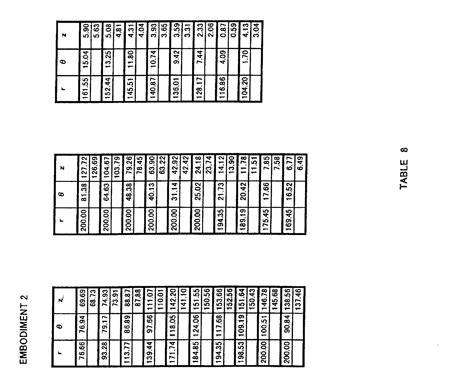
  • Fig. 1 is a front view of a propeller fan according to Embodiment 1 of the present invention;
  • Fig. 2 is a perspective view of (the negative pressure surface side of) the propeller fan in Embodiment 1 of the present invention;
  • Fig. 3 is a perspective view of (the positive pressure surface side of) the propeller fan in Embodiment 1 of the present invention;
  • Fig. 4 is a front view of a propeller fan in Comparison Example 1;
  • Fig. 5 is a perspective view of (the negative pressure surface side of) the propeller fan in Comparison Example 1;
  • Fig. 6 is a perspective view of (the positive pressure surface side of) the propeller fan in Comparison Example 1;
  • Fig. 7 is a partial section side view of a die for molding a propeller fan of the present invention;
  • Figs. 8A and 8C are side views of a fluid feeding device of the present invention, whereas Fig. 8B is a front configuration view of the fluid feeding device of the present invention;
  • Fig. 9 is a perspective view of an embodiment of a blower of the fluid feeding device of the present invention;
  • Fig. 10 is a perspective view of an embodiment of the blower of the fluid feeding device of the present invention;
  • Fig. 11 is a front view of a propeller fan according to Embodiment 21 of the present invention;
  • Fig. 12 is a perspective view of (the negative pressure surface side of) the propeller fan in Embodiment 21 of the present invention;
  • Fig. 13 is a perspective view of (the positive pressure surface side of) the propeller fan in Embodiment 21 of the present invention;
  • Fig. 14 is a front view of a propeller fan in Comparison Example 4;
  • Fig. 15 is a perspective view of (the negative pressure surface side of) the propeller fan in Comparison Example 4;
  • Fig. 16 is a perspective view of (the positive pressure surface side of) the propeller fan in Comparison Example 4;
  • Fig. 17 is a partial side section view of a die for molding a propeller fan of the present invention;
  • Figs. 18A and 18C are side views of a fluid feeding device of the present invention, whereas Fig. 18B is a front configuration view of the fluid feeding device of the present invention;
  • Fig. 19 is a perspective view of another embodiment of the blower of the fluid feeding device of the present invention;
  • Fig. 20 is a perspective view of yet another embodiment of the blower of the fluid feeding device of the present invention;
  • Fig. 21 is a front view of a propeller fan according to Embodiment 41 of the present invention;
  • Fig. 22 is a perspective view of (the negative pressure surface side of) the propeller fan in Embodiment 41 of the present invention;
  • Fig. 23 is a perspective view of (the positive pressure surface side of) the propeller fan in Embodiment 41 of the present invention;
  • Fig. 24 is a front view of a propeller fan in Comparison Example 7;
  • Fig. 25 is a perspective view of (the negative pressure surface side of) the propeller fan in Comparison Example 7;
  • Fig. 26 is a perspective view of (the positive pressure surface side of) the propeller fan in Comparison Example 7;
  • Fig. 27 is a partial side section view of a die for molding the propeller fan of the present invention;
  • Figs. 28A and 28C are side views of a fluid feeding device of the present invention, whereas Fig. 28B is a front configuration view of the fluid feeding device of the present invention;
  • Fig. 29 is a perspective view of a further embodiment of the blower for the fluid feeding device of the present invention; and
  • Fig. 30 is a perspective view of a yet further embodiment of the blower for the fluid feeding device of the present invention.
  • Best Modes for Carrying Out the Invention
    Embodiments of a propeller fan, a die for molding the propeller fan, and a fluid feeding device according to the present invention will be described below with reference to Figs. 1 to 30.
    Fig. 1 shows a front view of a propeller fan 1 of the present invention. Propeller fan 1 of the present invention is molded in one piece by synthetic resin such as, for example, AS resin with glass fiber. For propeller fan 1, the diameter D = 400 mm, the height in the axial direction (z direction) h = 140 mm, the number of blades n = 3, the expansion angle of a blade λ = 120 degrees (deg) and a boss ratio ν = 0.35 (boss diameter νD = 140 mm), and three blades 3 are radially and integrally provided on the periphery of a boss portion 2.
    Then, it is an important feature of the present invention that the shape of the surface of blade 3 of propeller fan 1 is obtained based on a base shape defined by specific coordinate values. Thus, the shape of a curved surface defined by coordinate values obtained by transforming the coordinate values in the base shape in the r,  and z directions using prescribed transformation formulas respectively is determined as the shape of the surface of blade 3 of propeller fan 1.
    The base shape of the present invention is typically defined by the coordinate values indicated in Tables 3 and 4 described earlier. However, the shape, which is defined by coordinate values obtained by uniformly transforming the coordinate values indicated in Tables 3 and 4 described earlier by e.g. multiplying the coordinate values with prescribed coefficients, should also be interpreted as equivalent to the base shape of the present invention.
    When expressed by a cylindrical coordinate system in which the z axis is set as a rotation axis of propeller fan 1, coordinates (r1, 1, z1u) of a surface on a negative pressure side of blade 3 and coordinates (r1, 1, z1d) of a surface on a positive pressure side of blade 3 are coordinate values obtained by transforming non-dimensionally expressed three-dimensional coordinate values indicated in Tables 3 and 4 using a transformation formula 13, and the surface on the negative pressure side and the surface on the positive pressure side are configured by curved surfaces defined by the obtained coordinate values, i.e. a curved surface specified by coordinate values indicated in Tables 5 and 6.
    It is noted that the curved surface may also be specified by coordinate values within the range of ±5 % of each coordinate value. Moreover, it may be possible to obtain coordinate values indicated in Tables 5 and 6 using coordinate values obtained by uniformly transforming the coordinate values indicated in Tables 3 and 4 described earlier. However, this should be interpreted as a modification within the range of equivalent to the present invention, since it can be applied only by slightly modifying transformation 13.
    Figure 00310001
    Figure 00320001
    Figure 00330001
    Fig. 1 shows a cylindrical coordinate system of r and  by dashed lines. It is noted that, though the z axis is not shown in Fig. 1, the z axis is a line passing the center of rotation 0 of boss portion 2 of propeller fan 1 in Fig. 1 and perpendicular to the plane of the drawing (that is, a line overlapping with a core of the rotation axis of propeller fan 1).
    In Fig. 1, for blade 3 of propeller fan 1, lines are drawn in the r direction that divide the blade at intervals of every 10 mm in the range between 80 mm and 190 mm, and lines are drawn that divide the blade in the  direction at intervals of every 5 deg in the range between 0 deg and 125 deg, a coordinate value of z at each crossing point being indicated in Table 5. Here, the top of each column indicates a value on the negative pressure surface side (suction side) of the propeller fan, whereas the bottom of each column indicates a value on the positive pressure surface side (blowing side). Moreover, each coordinate value of r, , z at an outer edge portion of blade 3 having  within the range between 0 deg and 125 deg are indicated in Table 6.
    It is noted that blade 3 is made thicker at a root portion of blade 3. Moreover, the shape of the surface of blade 3 may be smooth, or may be provided with concavities and convexities in a form of grooves, protrusions or dimples. Furthermore, the trailing edge of blade 3 may have a shape of saw teeth. Note that, in each transformation formula, d and fu = fd are indicated as optional because the shape of the propeller fan can be the same irrespective of a value selected for d and fu = fd.
    Moreover, propeller fan 1 of the present invention may be molded in one piece by synthetic resin such as ABS (acrylonitrile-butadiene-styrene) resin or polypropylene (PP), or may be integrally molded in one piece by synthetic resin having an increased intensity by including mica or the like, or may be non-integrally molded.
    Fig. 7 shows an example of a propeller-fan-molding die 4 for forming propeller fan 1 shown in Fig. 1. Die 4 is for molding propeller fan 1 by synthetic resin, and has a fixed-side die 5 and a movable-side die 6, as shown in Fig. 7.
    Then, the shape of a cavity defined by the both dies 5 and 6 is made approximately the same as the shape of propeller fan 1. Coordinates (r1, 1, z1u) on the die surface of a portion forming the surface of blade 3 in fixed-side die 5 described above and coordinates (r1, 1, z1d) on the die surface of a portion forming the surface of blade 3 in movable-side die 6 are obtained by transforming non-dimensionally expressed three-dimensional coordinate values indicated in Tables 3 and 4 using a transformation formula 14 below.
    Figure 00350001
    That is, fixed-side die 5 and movable-side die 6 have curved portions respectively specified by coordinate values indicated in Tables 5 and 6. It is noted that, in this case also, each curved surface may be specified by coordinate values within the range of ±5 % of each coordinate value.
    Here, the dimension of the curved shape of the die may be determined in consideration of mold shrinkage. In this case, the coordinate data above may be corrected in consideration of the mold shrinkage, warping and deformation, to form molding die 4, such that propeller fan 1 having blade 3 with a three-dimensional curved surface specified by coordinate values within the range of ±5 % of three-dimensional coordinate values indicated in Tables 5 and 6 above is formed after the mold shrinkage, and these are encompassed by the molding die of the present invention.
    Moreover, though die 4 for molding the propeller fan in the present embodiment includes the negative pressure side surface of propeller fan 1 formed by fixed-side die 5 and a positive pressure side surface of propeller fan formed by movable-side die 6 as shown in Fig. 7, it may be possible to form the positive pressure side surface of propeller fan 1 by fixed-side die 5 and the negative pressure side surface of propeller fan 1 by movable-side die 6.
    Embodiments and comparison examples of the present invention will be described below in detail.
    Embodiment 1
    Propeller fan 1 shown in Fig. 1 having the diameter D = 400 mm, the height in the axial direction (z direction) h = 140 mm, the number of blades n = 3, the expansion angle of a blade λ = 120 deg, the boss ratio ν = 0.35 (boss diameter νD = 140 mm) was formed such that the surface of the blade is a three-dimensional curved surface specified by Tables 5 and 6. Note that Figs. 2 and 3 each shows a perspective view of propeller fan 1 in the present Embodiment 1.
    Embodiment 2
    Propeller fan 1 having the diameter D = 400 mm, the height in the axial direction (z direction) h = 154 mm, the number of blades n = 3, the expansion angle of a blade λ = 120 deg, the boss ratio ν = 0.35 (boss diameter νD = 140 mm) was formed such that the surface of the blade is a curved surface formed by transforming the curved surface defined by non-dimensionally expressed three-dimensional coordinates specified by Tables 3 and 4 using a transformation formula 15 below, i.e. a three-dimensional curved surface specified by Tables 7 and 8.
    Figure 00370001
    Figure 00380001
    Figure 00390001
    Embodiment 3
    Propeller fan 1 having the diameter D = 400 mm, the height in the axial direction (z direction) h = 147 mm, the number of blades n = 3, the expansion angle of a blade λ = 120 deg, the boss ratio ν = 0.35 (boss diameter νD = 140 mm) was formed to have a curved surface formed by transforming the curved surface defined by non-dimensionally expressed three-dimensional coordinates specified by Tables 3 and 4 using a transformation formula 16 below, i.e. a three-dimensional curved surface specified by Tables 9 and 10.
    Figure 00400001
    Figure 00410001
    Figure 00420001
    Embodiment 4
    Propeller fan 1 having the diameter D = 400 mm, the height in the axial direction (z direction) h = 133 mm, the number of blades n = 3, the expansion angle of a blade λ = 120 deg, the boss ratio ν = 0.35 (boss diameter νD = 140 mm) was formed to have a curved surface formed by transforming the curved surface defined by non-dimensionally expressed three-dimensional coordinates specified by Tables 3 and 4 using a transformation formula 17 below, i.e. a three-dimensional curved surface specified by Tables 11 and 12.
    Figure 00430001
    Figure 00440001
    Figure 00450001
    Embodiment 5
    Propeller fan 1 having the diameter D = 400 mm, the height in the axial direction (z direction) h = 126 mm, the number of blades n = 3, the expansion angle of a blade λ = 120 deg, the boss ratio ν = 0.35 (boss diameter νD = 140 mm) was formed to have a curved surface formed by transforming the curved surface defined by non-dimensionally expressed three-dimensional coordinates specified by Tables 3 and 4 using a transformation formula 18, i.e. a three-dimensional curved surface specified by Tables 13 and 14.
    Figure 00460001
    Figure 00470001
    Figure 00480001
    Embodiment 6
    Propeller fan 1 having the diameter D = 400 mm, the height in the axial direction (z direction) h = 112 mm, the number of blades n = 3, the expansion angle of a blade λ = 120 deg, the boss ratio ν = 0.35 (boss diameter νD = 140 mm) was formed to have a curved surface formed by transforming the curved surface defined by non-dimensionally expressed three-dimensional coordinates specified by Tables 3 and 4 using a transformation formula 19 below, i.e. a three-dimensional curved surface specified by Tables 15 and 16.
    Figure 00490001
    Figure 00500001
    Figure 00510001
    Embodiment 7
    Propeller fan 1 having the diameter D = 400 mm, the height in the axial direction (z direction) h = 126 mm, the number of blades n = 3, the expansion angle of a blade λ = 108 deg, the boss ratio ν = 0.35 (boss diameter νD = 140 mm) was formed to have a curved surface formed by transforming the curved surface defined by non-dimensionally expressed three-dimensional coordinates specified by Tables 3 and 4 using a transformation formula 20 below, i.e. a three-dimensional curved surface specified by Tables 17 and 18.
    Figure 00520001
    Figure 00530001
    Figure 00540001
    Embodiment 8
    Propeller fan 1 having the diameter D = 400 mm, the height in the axial direction (z direction) h = 140 mm, the number of blades n = 3, the expansion angle of a blade λ = 90 deg, the boss ratio ν = 0.35 (boss diameter νD = 140 mm) was formed to have a curved surface formed by transforming the curved surface defined by non-dimensionally expressed three-dimensional coordinates specified by Tables 3 and 4 using a transformation formula 21 below, i.e. a three-dimensional curved surface specified by Tables 19 and 20.
    Figure 00550001
    Figure 00560001
    Figure 00570001
    Embodiment 9
    Propeller fan 1 having the diameter D = 400 mm, the height in the axial direction (z direction) h = 140 mm, the number of blades n = 3, the expansion angle of a blade λ = 132 deg, the boss ratio ν = 0.35 (boss diameter νD = 140 mm) was formed to have a curved surface formed by transforming the curved surface defined by non-dimensionally expressed three-dimensional coordinates specified by Tables 3 and 4 using a transformation formula 22 below, i.e. a three-dimensional curved surface specified by Tables 21 and 22.
    Figure 00580001
    Figure 00590001
    Figure 00600001
    Embodiment 10
    Propeller fan 1 having the diameter D = 400 mm, the height in the axial direction (z direction) h = 140 mm, the number of blades n = 3, the expansion angle of a blade λ = 120 deg, the boss ratio ν = 0.275 (boss diameter νD = 110 mm) was formed to have a curved surface formed by transforming the curved surface defined by non-dimensionally expressed three-dimensional coordinates specified by Tables 3 and 4 using a transformation formula 23 below, i.e. a three-dimensional curved surface specified by Tables 23 and 24.
    Figure 00610001
    Figure 00620001
    Figure 00630001
    Embodiment 11
    Propeller fan 1 having the diameter D = 400 mm, the height in the axial direction (z direction) h = 112 mm, the number of blades n = 3, the expansion angle of a blade λ = 120 deg, the boss ratio ν = 0.35 (boss diameter νD = 140 mm) was formed to have a curved surface formed by transforming the curved surface defined by non-dimensionally expressed three-dimensional coordinates specified by Tables 3 and 4 using a transformation formula 24 below, i.e. a three-dimensional curved surface specified by Tables 25 and 26.
    Figure 00640001
    Figure 00650001
    Figure 00660001
    Embodiment 12
    Propeller fan 1 having the diameter D = 400 mm, the height in the axial direction (z direction) h = 112 mm, the number of blades n = 3, the expansion angle of a blade λ = 120 deg, the boss ratio ν = 0.35 (boss diameter νD = 140 mm) was formed to have a curved surface formed by transforming the curved surface defined by non-dimensionally expressed three-dimensional coordinates specified by Tables 3 and 4 using a transformation formula 25 below, i.e. a three-dimensional curved surface specified by Tables 27 and 28.
    Figure 00670001
    Figure 00680001
    Figure 00690001
    Embodiment 13
    Propeller fan 1 having the diameter D = 400 mm, the height in the axial direction (z direction) h = 112 mm, the number of blades n = 3, the expansion angle of a blade λ = 120 deg, the boss ratio ν = 0.35 (boss diameter νD = 140 mm) was formed to have a curved surface formed by transforming the curved surface defined by non-dimensionally expressed three-dimensional coordinates specified by Tables 3 and 4 using a transformation formula 26 below, i.e. a three-dimensional curved surface specified by Tables 29 and 30.
    Figure 00700001
    Figure 00710001
    Figure 00720001
    Embodiment 14
    Propeller fan 1 having the diameter D = 316 mm, the height in the axial direction (z direction) h = 100 mm, the number of blades n = 3, the expansion angle of a blade λ = 120 deg, the boss ratio ν = 0.272 (boss diameter νD = 86 mm) was formed to have a curved surface formed by transforming the curved surface defined by non-dimensionally expressed three-dimensional coordinates specified by Tables 3 and 4 using a transformation formula 27 below, i.e. a three-dimensional curved surface specified by Tables 31 and 32.
    Figure 00730001
    Figure 00740001
    Figure 00750001
    Embodiment 15
    Propeller fan 1 having the diameter D = 316 mm, the height in the axial direction (z direction) h = 100 mm, the number of blades n = 4, the expansion angle of a blade λ = 90 deg, the boss ratio ν = 0.272 (boss diameter νD = 86 mm) was formed to have a curved surface formed by transforming the curved surface defined by non-dimensionally expressed three-dimensional coordinates specified by Tables 3 and 4 using a transformation formula 28 below, i.e. a three-dimensional curved surface specified by Tables 33 and 34.
    Figure 00760001
    Figure 00770001
    Figure 00780001
    Embodiment 16
    Propeller fan 1 having the diameter D = 316 mm, the height in the axial direction (z direction) h = 100 mm, the number of blades n = 5, the expansion angle of a blade λ = 72 deg, the boss ratio ν = 0.272 (boss diameter νD = 86 mm) was formed to have a curved surface formed by transforming the curved surface defined by non-dimensionally expressed three-dimensional coordinates specified by Tables 3 and 4 using a transformation formula 29 below, i.e. a three-dimensional curved surface specified by Tables 35 and 36.
    Figure 00790001
    Figure 00800001
    Figure 00810001
    Embodiment 17
    Propeller fan 1 having the diameter D = 316 mm, the height in the axial direction (z direction) h = 100 mm, the number of blades n = 5, the expansion angle of a blade λ = 108.5 deg, the boss ratio ν = 0.272 (boss diameter νD = 86 mm) was formed to have a curved surface formed by transforming the curved surface defined by non-dimensionally expressed three-dimensional coordinates specified by Tables 3 and 4 using a transformation formula 30 below, i.e. a three-dimensional curved surface specified by Tables 37 and 38.
    Figure 00820001
    Figure 00830001
    Figure 00840001
    Embodiment 18
    Propeller fan 1 having the diameter D = 460 mm, the height in the axial direction (z direction) h = 161 mm, the number of blades n = 3, the expansion angle of a blade λ = 120 deg, the boss ratio ν = 0.326 (boss diameter νD = 150 mm) was formed to have a curved surface formed by transforming the curved surface defined by non-dimensionally expressed three-dimensional coordinates specified by Tables 3 and 4 using a transformation formula 31 below, i.e. a three-dimensional curved surface specified by Tables 39 and 40.
    Figure 00850001
    Figure 00860001
    Figure 00870001
    Embodiment 19
    Propeller fan 1 having the diameter D = 460 mm, the height in the axial direction (z direction) h = 168 mm, the number of blades n = 3, the expansion angle of a blade λ = 120 deg, the boss ratio ν = 0.326 (boss diameter νD = 150 mm) was formed to have a curved surface formed by transforming the curved surface defined by non-dimensionally expressed three-dimensional coordinates specified by Tables 3 and 4 using a transformation formula 32 below, i.e. a three-dimensional curved surface specified by Tables 41 and 42.
    Figure 00880001
    Figure 00890001
    Figure 00900001
    Embodiment 20
    Propeller fan 1 having the diameter D = 460 mm, the height in the axial direction (z direction) h = 140 mm, the number of blades n = 3, the expansion angle of a blade λ = 120 deg, the boss ratio ν = 0.326 (boss diameter νD = 150 mm) was formed to have a curved surface formed by transforming the curved surface defined by non-dimensionally expressed three-dimensional coordinates specified by Tables 3 and 4 using a transformation formula 33 below, i.e. a three-dimensional curved surface specified by Tables 43 and 44.
    Figure 00910001
    Figure 00920001
    Figure 00930001
    Comparison examples of the present invention will be described below with reference to Figs. 4 to 6. Fig. 4 is a front view of a propeller fan in Comparison Example 1, whereas Figs. 5 and 6 are perspective views of the propeller fan in Comparison Example 1.
    Comparison Example 1
    Propeller fan 1 shown in Fig. 4 having the diameter D = 400 mm, the height in the axial direction (z direction) h = 140 mm, the number of blades n = 3, the boss ratio ν = 0.35 (boss diameter νD = 140 mm) was formed such that the surface of a blade 3 is a three-dimensional curved surface specified by Table 45 below. A boss portion is denoted by 2 in the drawings. Note that r, , z are set as in Embodiment 1.
    Figure 00950001
    Comparison Example 2
    Propeller fan 1 having the diameter D = 316 mm, the height in the axial direction (z direction) h = 100 mm, the number of blades n = 5, the boss ratio ν = 0.253 (boss diameter νD = 80 mm) was formed such that the surface of a blade is a three-dimensional curved surface specified by Table 46 below. Note that r, , z are set as in Embodiment 1.
    Figure 00970001
    Comparison Example 3
    Propeller fan 1 having the diameter D = 460 mm, the height in the axial direction (z direction) h = 168 mm, the number of blades n = 3, the boss ratio ν = 0.35 (boss diameter νD = 161 mm) was formed such that the surface of a blade is a three-dimensional curved surface specified by Table 47 below. Note that r, , z are set as in Embodiment 1.
    Figure 00990001
    Each of the propeller fans as in Embodiments 1 to 20 and those in Comparison Examples 1 to 3 is attached to an outdoor unit of an air conditioner, and airflow, power consumption and noise are measured.
    First, each fan in Embodiments 1 to 13 and in Comparison Example 1 having the fan diameter of 400 was driven by a DC motor using an outdoor unit with a refrigeration capacity of a 28 kW class. The results are shown in Table 48 below.
    Figure 01010001
    Next, each fan in Embodiments 14 to 17 and in Comparison Example 2 having the fan diameter of 316 was driven by an AC motor using a built-in outdoor unit. The results are shown in Table 49 below.
    Figure 01030001
    Next, each fan in Embodiments 18 to 20 and in Comparison Example 3 having the fan diameter of 460 was driven by an AC motor using a multiple-type large outdoor unit. The results are shown in Table 50 below.
    Figure 01050001
    As can be seen from Table 48 above, it has become clear that the power consumption at the same air flow is reduced by 40 % and also the noise is reduced by 4-6 dB in the propeller fan shown in Embodiments 1 to 13, compared to the case with Comparison Example 1 with the propeller fan having the same diameter.
    Moreover, as can be seen from Table 49 above, it has become clear that the power consumption at the same air flow is reduced by 15-30 % and also the noise is reduced by 3-5 dB in the propeller fan shown in Embodiments 14 to 17, compared to the case with Comparison Example 2 with the propeller fan having the same diameter.
    Furthermore, as can be seen from Table 50 above, it has become clear that the power consumption at the same air flow is reduced by 40-45 % and also the noise is reduced by 3-5 dB in the propeller fan shown in Embodiments 18 to 20, compared to the case with Comparison Example 3 with the propeller fan having the same diameter.
    Moreover, as for Embodiments 1 to 6 in Table 48 above, when the same diameter D = 400 mm and the same expansion angle λ = 120 deg, Embodiment 1 where height h satisfies an equation 34 below, i.e. h = 140, had the highest superiority in efficiency and noise. c=λ=360/n=24007 ×hD
    Moreover, as for Embodiments 1, 8 and 9, in Table 48 above, when the same diameter D = 400 mm and the same height h = 140 mm, Embodiment 1 where blade expansion angle λ satisfies an equation 35 below, i.e. λ = 120, had the highest superiority in efficiency and noise. c=λ=360/n=24007 ×hD
    Furthermore, as for Embodiments 5 and 7 in Table 48 above, blade expansion angle λ where the same diameter D = 400 mm and the same height h = 126 mm was superior in Embodiment 7 to that in Embodiment 5. Therefore, when the former is not the same as the latter in an equation 36 below, the latter showed a superiority.
    Figure 01070001
    Moreover, in Embodiments 1 and 10 in Table 48 above, as for boss ratio ν where the same diameter D = 400 mm, the same height h = 140 mm and the same blade expansion angle λ = 120 deg, Embodiment 10 showed a superiority in efficiency and noise as in Embodiment 1, since, in Embodiment 10, transformation satisfying an equation 37 below is performed for Embodiment 1.
    Figure 01070002
    Further, in Embodiments 1, 6, and 11 to 13 in Table 48, the way of assigning eu, ed, fu, fd in the case that the same diameter D = 400 mm, the same height h = 112 mm and the same blade expansion angle λ = 120 deg will be described.
    In Embodiment 6, the ratio of h/D is smaller, i.e., the thickness of a wing is thinner, than that in Embodiment 1. Thus, the wing is largely deformed at rotation of the fan due to the centrifugal force applied on the wing (blade), reducing the height of the wing, and therefore degradation occurs in terms of efficiency and noise.
    To prevent this, relation among eu, ed, fu and fd is set according to the following transformation 38 to increase the thickness of the wing, resulting in Embodiments 11 to 13 being superior to Embodiment 6.
    Figure 01080001
    It is noted that, when eu < ed and fu > fd, the shape of the wing is largely deformed, which induces deterioration in efficiency and increase in noise, and when eu = ed and fu < fd, or eu > ed and fu < fd, or eu < ed and fu < fd, or when eu < ed and fu = fd, the shape of the wing cannot be formed.
    Moreover, as for Embodiments 14 to 16 in Table 49, Embodiment 14 in which the number of blades n in the case of the same diameter D = 316 mm, the same height h = 100 mm and blade expansion angle λ = 360/n assumes a value closest to the value indicated by equation 39 below, i.e., n = 3, had the highest superiority in efficiency and noise. 24007 ×hD = 24007 ×100316 = 108.5
    Moreover, when Embodiments 16 and 17 in Table 49 above are compared with each other, Embodiment 17 was superior to Embodiment 16. The comparison was made for blade expansion angle λ where the same diameter D = 316 mm, the same height h = 100 mm and the same number of blades n = 5. Therefore, when the former is not the same as the latter in an equation 40 below, the latter showed a superiority.
    Figure 01080002
    Moreover, as for Embodiments 18 to 20 in Table 50, Embodiment 18 was superior to Embodiments 19 and 20. The comparison was made for blade expansion angle λ and height h where the same diameter D = 460 mm and the same number of blades n = 3. Thus, when blade expansion angle λ and height h are selected, selection is made not only for λ to satisfy the first equation (the top equation) in an equation 41 below, but also for the number of blades n, blade expansion angle λ and height h to satisfy the second equation (the middle equation) in equation 41 below, to achieve a higher superiority. That is, in respect to the propeller fan according to the present invention, the third equation (the bottom equation) in equation 41 below is important to determine a design manual.
    Figure 01090001
    Next, a fluid feeding device according to the present invention will be described. A fluid feeding device 7 shown in Fig. 8 includes a blower 9 constituted by propeller fan 1 in Embodiment 1 and a drive motor 8, and feeds fluid out by blower 9.
    Examples of fluid feeding device having such a configuration include an air conditioner, an air cleaner, a humidifier, an electric fan, a fan heater, a cooling device, and a ventilator. Fluid feeding device 7 in the present embodiment is an outdoor unit 10 of an air conditioner.
    Outdoor unit 10 includes an outdoor heat exchanger 11, and efficiently exchanges heat by blower 9 described above. Here, blower 9 is installed in outdoor unit 10 by a motor angle 12, and a supply opening 13 of outdoor unit 10 is formed to be a bell mouth 14 as shown in Fig. 9.
    Moreover, blower 9 having a ring splasher 15 installed on the periphery of propeller fan 1, as shown in Fig. 10, may also be provided at fluid feeding device 7. Here, in an air conditioner of a type having an indoor unit and an outdoor unit formed in one piece to be attached to a window or the like, drain water may be splashed up and sprayed on outdoor heat exchanger 11, to further increase the efficiency.
    Outdoor unit 10 in the present embodiment is a quiet outdoor unit with reduced noise, since propeller fan 1 in Embodiment 1 is included therein. Moreover, propeller fan 1 has an increased fan efficiency, so that an efficient outdoor unit realizing energy-saving can be attained. It is presumed that propeller fans in other Embodiments can attain similar results.
    Next, other embodiments of a propeller fan, a die for molding the propeller fan, and a fluid feeding device according to the present invention will be described below with reference to Figs. 11 to 20.
    Fig. 11 shows a front view of propeller fan 1 of the present invention. Propeller fan 1 of the present invention is molded in one piece by synthetic resin such as, for example, AS resin with glass fiber. For propeller fan 1, the diameter D = 400 mm, the height in the axial direction (z direction) h = 140 mm, the number of blades n = 3, the expansion angle of a blade λ = 120 degrees (deg) and a boss ratio ν = 0.275 (boss diameter νD = 110 mm), and three blades 3 are radially and integrally provided on the periphery of boss portion 2.
    It is an important feature of the present invention that the shape of the surface of blade 3 of propeller fan 1 is obtained based on a base shape defined by specific coordinate values. Thus, the shape of a curved surface, which is defined by coordinate values obtained by transforming the coordinate values in the base shape in the r,  and z directions using prescribed transformation formulas respectively, is determined as the shape of the surface of blade 3 of propeller fan 1.
    The base shape of the present invention is typically defined by the coordinate values indicated in Table 102 described earlier. However, the shape, which is defined by coordinate values obtained by uniformly transforming the coordinate values indicated in Table 102 by e.g. multiplying the coordinate values with prescribed coefficients, should also be interpreted as equivalent to the base shape of the present invention.
    When expressed by a cylindrical coordinate system in which the z axis is set as a rotation axis of propeller fan 1, coordinates (r1, 1, z1u) of a surface on a negative pressure side of blade 3 and coordinates (r1, 1, z1d) of a surface on a positive pressure side of blade 3 are coordinate values obtained by transforming non-dimensionally expressed three-dimensional coordinate values indicated in Table 102 using a transformation formula 113 below, and the surface on the negative pressure side and the surface on the positive pressure side are configured by curved surfaces defined by the obtained coordinate values, i.e. a curved surface specified by coordinate values indicated in Table 103.
    It is noted that the curved surface may also be specified by coordinate values within the range of ±5 % of each coordinate value. Moreover, it may be possible to obtain coordinate values indicated in Table 103 using coordinate values obtained by uniformly transforming the coordinate values indicated in Table 102 described earlier. However, this should be interpreted as a modification within the range of equivalent to the present invention, since it can be applied only by slightly modifying transformation formula 13.
    Figure 01110001
    Figure 01120001
    Fig. 11 shows a cylindrical coordinate system of r and  by dashed lines. It is noted that, though the z axis is not shown in Fig. 11, the z axis is a line passing the center of rotation 0 of boss portion 2 of propeller fan 1 in Fig. 11 and perpendicular to the plane of the drawing (that is, a line overlapping with a core of the rotation axis of propeller fan 1).
    In Fig. 11, for blade 3 of propeller fan 1, lines are drawn in the r direction that divide the blade at intervals of every 10 mm in the range between 60 mm and 190 mm, and lines are drawn that divide the blade in the  direction at intervals of every 5 deg in the range between 0 deg and 125 deg, a coordinate value of z at each crossing point being indicated in Table 103. Here, the top of each column indicates a value on the negative pressure surface side (suction side) of the propeller fan, whereas the bottom of each column indicates a value on the positive pressure surface side (blowing side) thereof.
    It is noted that blade 3 is made thicker at a root portion of blade 3. Moreover, a rim of blade 3 is extremely thin for weight saving, so that the thickness may be partially increased compared to that defined by Table 103 in the case that a problem occurs in resin flowage at the time of molding. Moreover, the shape of the surface of blade 3 may be smooth, or may be provided with concavities and convexities in a form of grooves, protrusions or dimples. Furthermore, the trailing edge of blade 3 may have a shape of saw teeth. Not that, in each transformation formula, d and fu = fd are indicated as optional because the shape of the propeller fan can be the same irrespective of a value selected for d and fu = fd.
    Moreover, propeller fan 1 of the present invention may be molded in one piece by synthetic resin such as ABS (acrylonitrile-butadiene-styrene) resin or polypropylene (PP), or may be integrally molded in one piece by synthetic resin having an increased intensity by including mica or the like, or may be non-integrally molded.
    Fig. 17 shows an example of a propeller-fan-molding die 4 for forming propeller fan 1 shown in Fig. 11. Die 4 is for molding propeller fan 1 by synthetic resin, and has a fixed-side die 5 and a movable-side die 6, as shown in Fig. 17.
    Then, the shape of a cavity defined by the both dies 5 and 6 is made approximately the same as the shape of propeller fan 1. Coordinates (r1, 1, z1u) on the die surface of a portion forming the surface of blade 3 in fixed-side die 5 described above and coordinates (r1, 1, z1d) on the die surface of a portion forming the surface of blade 3 in movable-side die 6 are obtained by transforming non-dimensionally expressed three-dimensional coordinate values indicated in Table 102 using a transformation formula 114 below.
    Figure 01140001
    That is, fixed-side die 5 and movable-side die 6 have curved portions respectively specified by coordinate values indicated in Table 103. It is noted that, in this case also, each curved surface may be specified by coordinate values within the range of ±5 % of each coordinate value.
    Here, the dimension of the curved surface of the die may be determined in consideration of mold shrinkage. In this case, the coordinate data above may be corrected in consideration of the mold shrinkage, warping and deformation, to form molding die 4, such that propeller fan 1 having blade 3 with a three-dimensional curved surface specified by coordinate values within the range of ±5 % of three-dimensional coordinate values indicated in Table 103 above is formed after the mold shrinkage, and these are encompassed by the molding die of the present invention.
    Moreover, though die 4 for molding the propeller fan in the present embodiment includes the negative pressure side surface of propeller fan 1 formed by fixed-side die 5 and a positive pressure side surface of propeller fan formed by movable-side die 6 as shown in Fig. 17, it may be possible to form the positive pressure side surface of propeller fan 1 by fixed-side die 5 and the negative pressure side surface of propeller fan 1 by movable-side die 6.
    Other embodiments and comparison examples of the present invention will be described below in detail.
    Embodiment 21
    Propeller fan 1 shown in Fig. 11 having the diameter D = 400 mm, the height in the axial direction (z direction) h = 140 mm, the number of blades n = 3, the expansion angle of a blade λ = 120 deg, the boss ratio ν = 0.275 (boss diameter νD = 110 mm) was formed such that the surface of the blade is a three-dimensional curved surface as indicated in Table 103. Note that Figs. 12 and 13 each shows a perspective view of propeller fan 1 in the present Embodiment 21.
    Embodiment 22
    Propeller fan 1 having the diameter D = 400 mm, the height in the axial direction (z direction) h = 154 mm, the number of blades n = 3, the expansion angle of a blade λ = 120 deg, the boss ratio ν = 0.275 (boss diameter νD = 110 mm) was formed such that the surface of the blade is a curved surface formed by transforming the curved surface defined by non-dimensionally expressed three-dimensional coordinates specified by Table 102 using a transformation formula 115 below, i.e. a three-dimensional curved surface specified by Table 104.
    Figure 01160001
    Figure 01170001
    Embodiment 23
    Propeller fan 1 having the diameter D = 400 mm, the height in the axial direction (z direction) h = 147 mm, the number of blades n = 3, the expansion angle of a blade λ = 120 deg, the boss ratio ν = 0.275 (boss diameter νD = 110 mm) was formed to have a curved surface formed by transforming the curved surface defined by non-dimensionally expressed three-dimensional coordinates specified by Table 102 using a transformation formula 116 below, i.e. a three-dimensional curved surface specified by Table 105.
    Figure 01180001
    Figure 01190001
    Embodiment 24
    Propeller fan 1 having the diameter D = 400 mm, the height in the axial direction (z direction) h = 133 mm, the number of blades n = 3, the expansion angle of a blade λ = 120 deg, the boss ratio ν = 0.275 (boss diameter νD = 110 mm) was formed to have a curved surface formed by transforming the curved surface defined by non-dimensionally expressed three-dimensional coordinates specified by Table 102 using a transformation formula 117 below, i.e. a three-dimensional curved surface specified by Table 106.
    Figure 01200001
    Figure 01210001
    Embodiment 25
    Propeller fan 1 having the diameter D = 400 mm, the height in the axial direction (z direction) h = 126 mm, the number of blades n = 3, the expansion angle of a blade λ = 120 deg, the boss ratio ν = 0.275 (boss diameter νD = 110 mm) was formed to have a curved surface formed by transforming the curved surface defined by non-dimensionally expressed three-dimensional coordinates specified by Table 102 using a transformation formula 118 below, i.e. a three-dimensional curved surface specified by Table 107.
    Figure 01220001
    Figure 01230001
    Embodiment 26
    Propeller fan 1 having the diameter D = 400 mm, the height in the axial direction (z direction) h = 112 mm, the number of blades n = 3, the expansion angle of a blade λ = 120 deg, the boss ratio ν = 0.275 (boss diameter νD = 110 mm) was formed to have a curved surface formed by transforming the curved surface defined by non-dimensionally expressed three-dimensional coordinates specified by Table 102 using a transformation formula 119 below, i.e. a three-dimensional curved surface specified by Table 108.
    Figure 01240001
    Figure 01250001
    Embodiment 27
    Propeller fan 1 having the diameter D = 400 mm, the height in the axial direction (z direction) h = 126 mm, the number of blades n = 3, the expansion angle of a blade λ = 108 deg, the boss ratio ν = 0.275 (boss diameter νD = 110 mm) was formed to have a curved surface formed by transforming the curved surface defined by non-dimensionally expressed three-dimensional coordinates specified by Table 102 using a transformation formula 120 below, i.e. a three-dimensional curved surface specified by Table 109.
    Figure 01260001
    Figure 01270001
    Embodiment 28
    Propeller fan 1 having the diameter D = 400 mm, the height in the axial direction (z direction) h = 140 mm, the number of blades n = 3, the expansion angle of a blade λ = 90 deg, the boss ratio ν = 0.275 (boss diameter νD = 110 mm) was formed to have a curved surface formed by transforming the curved surface defined by non-dimensionally expressed three-dimensional coordinates specified by Table 102 using a transformation formula 121 below, i.e. a three-dimensional curved surface specified by Table 110.
    Figure 01280001
    Figure 01290001
    Embodiment 29
    Propeller fan 1 having the diameter D = 400 mm, the height in the axial direction (z direction) h = 140 mm, the number of blades n = 3, the expansion angle of a blade λ = 132 deg, the boss ratio ν = 0.275 (boss diameter νD = 110 mm) was formed to have a curved surface formed by transforming the curved surface defined by non-dimensionally expressed three-dimensional coordinates specified by Table 102 using a transformation formula 122 below, i.e. a three-dimensional curved surface specified by Table 111.
    Figure 01300001
    Figure 01310001
    Embodiment 30
    Propeller fan 1 having the diameter D = 400 mm, the height in the axial direction (z direction) h = 140 mm, the number of blades n = 3, the expansion angle of a blade λ = 120 deg, the boss ratio ν = 0.35 (boss diameter νD = 140 mm) was formed to have a curved surface formed by transforming the curved surface defined by non-dimensionally expressed three-dimensional coordinates specified by Table 102 using a transformation formula 123 below, i.e. a three-dimensional curved surface specified by Table 112.
    Figure 01320001
    Figure 01330001
    Embodiment 31
    Propeller fan 1 having the diameter D = 400 mm, the height in the axial direction (z direction) h = 112 mm, the number of blades n = 3, the expansion angle of a blade λ = 120 deg, the boss ratio ν = 0.275 (boss diameter νD = 110 mm) was formed to have a curved surface formed by transforming the curved surface defined by non-dimensionally expressed three-dimensional coordinates specified by Table 102 using a transformation formula 124 below, i.e. a three-dimensional curved surface specified by Table 113.
    Figure 01340001
    Figure 01350001
    Embodiment 32
    Propeller fan 1 having the diameter D = 400 mm, the height in the axial direction (z direction) h = 112 mm, the number of blades n = 3, the expansion angle of a blade λ = 120 deg, the boss ratio ν = 0.275 (boss diameter νD = 110 mm) was formed to have a curved surface formed by transforming the curved surface defined by non-dimensionally expressed three-dimensional coordinates specified by Table 102 using a transformation formula 125 below, i.e. a three-dimensional curved surface specified by Table 114.
    Figure 01360001
    Figure 01370001
    Embodiment 33
    Propeller fan 1 having the diameter D = 400 mm, the height in the axial direction (z direction) h = 112 mm, the number of blades n = 3, the expansion angle of a blade λ = 120 deg, the boss ratio ν = 0.275 (boss diameter νD = 110 mm) was formed to have a curved surface formed by transforming the curved surface defined by non-dimensionally expressed three-dimensional coordinates specified by Table 102 using a transformation formula 126 below, i.e. a three-dimensional curved surface specified by Table 115.
    Figure 01380001
    Figure 01390001
    Embodiment 34
    Propeller fan 1 having the diameter D = 316 mm, the height in the axial direction (z direction) h = 100 mm, the number of blades n = 3, the expansion angle of a blade λ = 120 deg, the boss ratio ν = 0.272 (boss diameter νD = 86 mm) was formed to have a curved surface formed by transforming the curved surface defined by non-dimensionally expressed three-dimensional coordinates specified by Table 102 using a transformation formula 127 below, i.e. a three-dimensional curved surface specified by Table 116.
    Figure 01400001
    Figure 01410001
    Embodiment 35
    Propeller fan 1 having the diameter D = 316 mm, the height in the axial direction (z direction) h = 100 mm, the number of blades n = 4, the expansion angle of a blade λ = 90 deg, the boss ratio ν = 0.272 (boss diameter νD = 86 mm) was formed to have a curved surface formed by transforming the curved surface defined by non-dimensionally expressed three-dimensional coordinates specified by Table 102 using a transformation formula 128 below, i.e. a three-dimensional curved surface specified by Table 117.
    Figure 01420001
    Figure 01430001
    Embodiment 36
    Propeller fan 1 having the diameter D = 316 mm, the height in the axial direction (z direction) h = 100 mm, the number of blades n = 5, the expansion angle of a blade λ = 72 deg, the boss ratio ν = 0.272 (boss diameter νD = 86 mm) was formed to have a curved surface formed by transforming the curved surface defined by non-dimensionally expressed three-dimensional coordinates specified by Table 102 using a transformation formula 129 below, i.e. a three-dimensional curved surface specified by Table 118.
    Figure 01440001
    Figure 01450001
    Embodiment 37
    Propeller fan 1 having the diameter D = 316 mm, the height in the axial direction (z direction) h = 100 mm, the number of blades n = 5, the expansion angle of a blade λ = 108.5 deg, the boss ratio ν = 0.272 (boss diameter νD = 86 mm) was formed to have a curved surface formed by transforming the curved surface defined by non-dimensionally expressed three-dimensional coordinates specified by Table 102 using a transformation formula 130 below, i.e. a three-dimensional curved surface specified by Table 119.
    Figure 01460001
    Figure 01470001
    Embodiment 38
    Propeller fan 1 having the diameter D = 460 mm, the height in the axial direction (z direction) h = 161 mm, the number of blades n = 3, the expansion angle of a blade λ = 120 deg, the boss ratio ν = 0.326 (boss diameter νD = 150 mm) was formed to have a curved surface formed by transforming the curved surface defined by non-dimensionally expressed three-dimensional coordinates specified by Table 102 using a transformation formula 131 below, i.e. a three-dimensional curved surface specified by Table 120.
    Figure 01480001
    Figure 01490001
    Embodiment 39
    Propeller fan 1 having the diameter D = 460 mm, the height in the axial direction (z direction) h = 168 mm, the number of blades n = 3, the expansion angle of a blade λ = 120 deg, the boss ratio ν = 0.326 (boss diameter νD = 150 mm) was formed to have a curved surface formed by transforming the curved surface defined by non-dimensionally expressed three-dimensional coordinates specified by Table 102 using a transformation formula 132 below, i.e. a three-dimensional curved surface specified by Table 121.
    Figure 01500001
    Figure 01510001
    Embodiment 40
    Propeller fan 1 having the diameter D = 460 mm, the height in the axial direction (z direction) h = 140 mm, the number of blades n = 3, the expansion angle of a blade λ = 120 deg, the boss ratio ν = 0.326 (boss diameter νD = 150 mm) was formed to have a curved surface formed by transforming the curved surface defined by non-dimensionally expressed three-dimensional coordinates specified by Table 102 using a transformation formula 133 below, i.e. a three-dimensional curved surface specified by Table 122.
    Figure 01520001
    Figure 01530001
    Comparison examples of the present invention will be described below with reference to Figs. 14 to 16. Fig. 14 is a front view of a propeller fan in Comparison Example 4, whereas Figs. 15 and 16 are perspective views of the propeller fan in Comparison Example 4.
    Comparison Example 4
    Propeller fan 1 shown in Fig. 4 having the diameter D = 400 mm, the height in the axial direction (z direction) h = 140 mm, the number of blades n = 3, the boss ratio ν = 0.35 (boss diameter νD = 140 mm) was formed such that the surface of blade 3 is a three-dimensional curved surface specified by Table 123 below. A boss portion is denoted by 2 in the drawings. Note that r, , z are set as in Embodiment 21.
    Figure 01550001
    Comparison Example 5
    Propeller fan 1 having the diameter D = 316 mm, the height in the axial direction (z direction) h = 100 mm, the number of blades n = 5, the boss ratio ν = 0.253 (boss diameter νD = 80 mm) was formed such that the surface of a blade is a three-dimensional curved surface specified by Table 124 below. Note that r, , z are set as in Embodiment 21.
    Figure 01570001
    Comparison Example 6
    Propeller fan 1 having the diameter D = 460 mm, the height in the axial direction (z direction) h = 168 mm, the number of blades n = 3, the boss ratio ν = 0.35 (boss diameter νD = 161 mm) was formed such that the surface of a blade is a three-dimensional curved surface specified by Table 125 below. Note that r, , z are set as in Embodiment 21.
    Figure 01590001
    Each of the propeller fans as in Embodiments 21 to 40 and those in Comparison Examples 4 to 6 is attached to an outdoor unit of an air conditioner, and airflow, power consumption and noise are measured.
    First, each fan in Embodiments 21 to 33 and in Comparison Example 4 having the fan diameter of 400 was driven by a DC motor using an outdoor unit with a refrigeration capacity of a 28 kW class. The results are shown in Table 126 below.
    Figure 01610001
    Next, each fan in Embodiments 34 to 37 and in Comparison Example 5 having the fan diameter of 316 was driven by an AC motor using an outdoor unit of a built-in type. The results are shown in Table 127 below.
    Figure 01630001
    Next, each fan in Embodiments 38 to 40 and in Comparison Example 6 having the fan diameter of 460 was driven by an AC motor using a multiple-type large outdoor unit. The results are shown in Table 128 below.
    Figure 01650001
    As can be seen from Table 126 above, it has become clear that the power consumption at the same air flow is reduced by 40 % and also the noise is reduced by 4-7 dB in the propeller fan shown in Embodiments 21 to 33, compared to the case with Comparison Example 1 with the propeller fan having the same diameter. It is noted that no separation noise occurred, which is a problem common to a thin blade, and thus there was no increase of noise.
    Moreover, weight was reduced by approximately 25 % for each propeller fan shown in Embodiments 21 to 33 compared to Comparison Example 4, without degradation of its performance, and thus the cost was also reduced. In addition, the 25% of weight saving can realize reduction of startup torque occurred at startup of the blower and also reduction of cost for the drive motor. It is noted that the deformation of a blade, which is a problem common to a thin blade, was approximately equal to that in Comparison Example 4.
    Moreover, as can be seen from Table 127 above, it has become clear that the power consumption at the same air flow is reduced by 15-30 % and also the noise can be reduced by 4-6 dB in the propeller fan shown in Embodiments 34 to 37, compared to the case with Comparison Example 5 for the propeller fan having the same diameter. It is noted that no separation noise occurred that is a problem common to a thin blade, and thus there was no increase of noise.
    Moreover, weight was reduced by 20 % for each propeller fan shown in Embodiments 34 to 37 compared to Comparison Example 5, without degradation of its performance, and thus the cost was also reduced. In addition, the 20% of weight saving can realize reduction of startup torque occurred at startup of the blower and also reduction of cost for the drive motor. It is noted that the deformation of a blade, which is a problem common to a thin blade, was approximately equal to that in Comparison Example 5.
    Furthermore, as can be seen from Table 128 above, it has become clear that the power consumption at the same air flow is reduced by 42-47 % and also the noise is reduced by 4-6 dB in the propeller fan shown in Embodiments 38 to 40, compared to the case with Comparison Example 6 with the propeller fan having the same diameter. It is noted that no separation noise occurred that is a problem common to a thin blade, and thus there was no increase of noise.
    Moreover, weight was reduced by 20 % for each propeller fan shown in Embodiments 38 to 40 compared to Comparison Example 6, without degradation of its performance, and thus the cost was also reduced. In addition, the 20% of weight saving can realize reduction of startup torque at startup of the blower and also reduction of cost for the drive motor. It is noted that the deformation of a blade that is a problem common to a thin blade was approximately equal to that in Comparison Example 6.
    Moreover, as for Embodiments 21 to 26 in Table 126 above, when the same diameter D = 400 mm and the same expansion angle λ = 120 deg, Embodiment 21 where height h satisfies an equation 134 below, i.e. h = 140, had the highest superiority in efficiency and noise. c=λ=360/n=24007 ×hD
    Moreover, as for Embodiments 21, 28 and 29 in Table 126 above, when the same diameter D = 400 mm and the same height h = 140 mm, Embodiment 21 where blade expansion angle λ satisfies an equation 135 below, i.e. λ = 120, had the highest superiority in efficiency and noise. c=λ=360/n=24007 ×hD
    Furthermore, as for Embodiments 25 and 27 in Table 126 above, blade expansion angle λ where the same diameter D = 400 mm and the same height h = 126 mm was superior in Embodiment 27 to that in Embodiment 25. Therefore, when the former is not the same as the latter in an equation 136 below, the latter showed a superiority.
    Figure 01680001
    Moreover, in Embodiments 21 and 30 in Table 126 above, as for boss ratio ν where the same diameter D = 400 mm, the same height h = 140 mm and the same blade expansion angle λ = 120 deg, Embodiment 30 showed a superiority in efficiency and noise as in Embodiment 21, since, in Embodiment 30, transformation is performed for Embodiment 21 to satisfy an equation 137 below.
    Figure 01680002
    Further, in Embodiments 21, 36, and 31 to 33 in Table 126, the way of assigning eu, ed, fu, fd in the case that the same diameter D = 400 mm, the same height h = 112 mm and the same blade expansion angle λ = 120 deg will be described.
    In Embodiment 26, the ratio of h/D is smaller, i.e., the thickness of a wing is thinner, than that in Embodiment 21. Thus, the wing is largely deformed at rotation of the fan due to the centrifugal force applied on the wing (blade), reducing the height of the wing, and therefore degradation occurs in terms of efficiency and noise.
    To prevent this, relation among eu, ed, fu and fd is set according to the following transformation formula 38 to increase the thickness of the wing, resulting in Embodiments 31 to 33 being superior to Embodiment 26.
    Figure 01690001
    It is noted that, when eu < ed and fu > fd, the shape of the wing is largely deformed, which induces deterioration in efficiency and increase in noise, and when eu = ed and fu < fd, or eu > ed and fu < fd, or eu < ed and fu < fd, or when eu < ed and fu = fd, the shape of the wing cannot be formed.
    Moreover, as for Embodiments 34 to 36 in Table 127, Embodiment 34 in which the number of blades n in the case of the same diameter D = 316 mm, the same height h = 100 mm and blade expansion angle λ = 360/n assumes a value closest to the value indicated by an equation 139 below, i.e., n = 3, had the highest superiority in efficiency and noise. 24007 ×hD = 24007 ×100316 = 108.5
    Moreover, when Embodiments 36 and 37 in Table 127 above are compared with each other, Embodiment 37 was superior to Embodiment 36. The comparison was made for blade expansion angle λ where the same diameter D = 316 mm, the same height h = 100 mm and the same number of blades n = 5. Therefore, when the former is not the same as the latter in an equation 140 below, the latter showed a superiority.
    Figure 01690002
    Moreover, as for Embodiments 38 to 40 in Table 128, Embodiment 38 was superior to Embodiments 39 and 40. The comparison was made for blade expansion angle λ and height h where the same diameter D = 460 mm and the same number of blades n = 3. Thus, when blade expansion angle λ and height h are selected, selection is made not only for λ to satisfy the first equation (the top equation) in an equation 141 below, but also for the number of blades n, blade expansion angle λ and height h to satisfy the second equation (the middle equation) in equation 141, to achieve a higher superiority. That is, in respect to the propeller fan according to the present invention, the third equation (the bottom equation) in equation 141 below is important to determine a design manual.
    Figure 01700001
    Next, a fluid feeding device according to the present invention will be described. A fluid feeding device 7 shown in Fig. 18 includes a blower 9 constituted by propeller fan 1 in Embodiment 21 and a drive motor 8, and fluid is fed out by blower 9.
    Examples of the fluid feeding device having such a configuration include an air conditioner, an air cleaner, a humidifier, a dehumidifier, an electric fan, a fan heater, a cooling device, and a ventilator. Fluid feeding device 7 in the present embodiment is an outdoor unit 10 of an air conditioner.
    Outdoor unit 10 includes an outdoor heat exchanger 11, and efficiently exchanges heat by blower 9 described above. Here, blower 9 is installed in outdoor unit 10 by a motor angle 12, and a supply opening 13 of outdoor unit 10 is formed to be a bell mouth 14 as shown in Fig. 19.
    Moreover, blower 9 having a ring splasher 15 installed on the periphery of propeller fan 1, as shown in Fig. 20, may also be provided at fluid feeding device 7. Here, in an air conditioner of a type having an indoor unit and an outdoor unit formed in one piece to be attached to a window or the like, drain water may be splashed up and sprayed on outdoor heat exchanger 11, to further increase the efficiency.
    Outdoor unit 10 in the present embodiment is a quiet outdoor unit with reduced noise, since propeller fan 1 in Embodiment 21 is included therein. Moreover, propeller fan 1 has an increased fan efficiency, so that an efficient outdoor unit realizing energy-saving can be attained. Furthermore, propeller fan 1 can be reduced in weight so that outdoor unit 10 can also achieve weight saving. It is presumed that propeller fans in other embodiments may also attain similar results.
    Further embodiments of a propeller fan, a die for molding the propeller fan, and a fluid feeding device according to the present invention will be described below with reference to Figs. 21 to 30.
    Fig. 21 shows a front view of propeller fan 1 according to the present invention. Propeller fan 1 of the present invention is molded in one piece by synthetic resin such as, for example, AS resin with glass fiber. For propeller fan 1, the diameter D = 400 mm, the height in the axial direction (z direction) h = 140 mm, the number of blades n = 3, the expansion angle of a blade λ = 120 degrees (deg) and a boss ratio ν = 0.275 (boss diameter νD = 110 mm), and three blades 3 are radially and integrally provided on the periphery of boss portion 2.
    It is an important feature of the present invention that the shape of the surface of blade 3 of propeller fan 1 is obtained based on a base shape defined by specific coordinate values. Thus, the shape of a curved surface, which is defined by coordinate values obtained by transforming the coordinate values in the base shape in the r,  and z directions using prescribed transformation formulas respectively, is determined as the shape of the surface of blade 3 of propeller fan 1.
    The base shape of the present invention is typically defined by the coordinate values indicated in Table 202 described earlier. However, the shape, which is defined by coordinate values obtained by uniformly transforming the coordinate values indicated in Table 202 by e.g. multiplying the coordinate values with prescribed coefficients, should also be interpreted as equivalent to the base shape of the present invention.
    When expressed by a cylindrical coordinate system in which the z axis is set as a rotation axis of propeller fan 1, coordinates (r1, 1, z1u) of a surface on a negative pressure side of blade 3 and coordinates (r1, 1, z1d) of a surface on a positive pressure side of blade 3 are coordinate values obtained by transforming non-dimensionally expressed three-dimensional coordinate values indicated in Table 202 using a transformation formula 213 below, and the surface on the negative pressure side and the surface on the positive pressure side are configured by curved surfaces defined by the obtained coordinate values, i.e. a curved surface specified by coordinate values indicated in Table 203.
    It is noted that the curved surface may also be specified by coordinate values within the range of ±5 % of each coordinate value. Moreover, it may be possible to obtain coordinate values indicated in Table 203 using coordinate values obtained by uniformly transforming the coordinate values indicated in Table 202 described earlier. However, this should be interpreted as a modification within the range of equivalent to the present invention, since it can be applied only by slightly modifying transformation formula 213.
    Figure 01730001
    Figure 01740001
    Fig. 21 shows a cylindrical coordinate system of r and  by dashed lines. It is noted that, though the z axis is not shown in Fig. 21, the z axis is a line passing the center of rotation 0 of boss portion 2 of propeller fan 1 in Fig. 21 and perpendicular to the plane of the drawing (that is, a line overlapping with a core of the rotation axis of propeller fan 1).
    In Fig. 21, for blade 3 of propeller fan 1, lines are drawn in the r direction that divide the blade at intervals of every 10 mm in the range between 60 mm and 190 mm, and lines are drawn that divide the blade in the  direction at intervals of every 5 deg in the range between 0 deg and 125 deg, a coordinate value of z at each crossing point being indicated in Table 203. Here, the top of each column indicates a value on the negative pressure surface side (suction side) of the propeller fan, whereas the bottom of each column indicates a value on the positive pressure surface side (blowing side) thereof.
    It is noted that blade 3 may be made thicker at a root portion of blade 3. Moreover, a rim of blade 3 is extremely thin for weight saving, so that the thickness may be partially increased compared to that defined by Table 203 in the case that a problem occurs in resin flowage at the time of molding. Moreover, the shape of the surface of blade 3 may be smooth, or may be provided with concavities and convexities in a form of grooves, protrusions or dimples. Furthermore, the trailing edge of blade 3 may have a shape of saw teeth. Not that, in each transformation formula, d and fu = fd are indicated as optional because the shape of the propeller fan can be the same irrespective of a value selected for d and fu = fd.
    Moreover, propeller fan 1 of the present invention may be molded in one piece by synthetic resin such as ABS (acrylonitrile-butadiene-styrene) resin or polypropylene (PP), or may be integrally molded in one piece by synthetic resin having an increased intensity by including mica or the like, or may be non-integrally molded.
    Fig. 27 shows an example of a propeller-fan-molding die 4 for forming propeller fan 1 shown in Fig. 21. Die 4 is for molding propeller fan 1 by synthetic resin, and has a fixed-side die 5 and a movable-side die 6, as shown in Fig. 27.
    Then, the shape of a cavity defined by the both dies 5 and 6 is made approximately the same as the shape of propeller fan 1. Coordinates (r1, 1, z1u) on the die surface of a portion forming the surface of blade 3 in fixed-side die 5 described above and coordinates (r1, 1, z1d) on the die surface of a portion forming the surface of blade 3 in movable-side die 6 are obtained by transforming non-dimensionally expressed three-dimensional coordinate values indicated in Table 202 using a transformation formula 214 below.
    Figure 01760001
    That is, fixed-side die 5 and movable-side die 6 have curved portions respectively specified by coordinate values indicated in Table 203. It is noted that, in this case also, each curved surface may be specified by coordinate values within the range of ±5 % of each coordinate value.
    Here, the dimension of the curved surface of the die may be determined in consideration of mold shrinkage. In this case, the coordinate data above may be corrected in consideration of the mold shrinkage, warping and deformation, to form molding die 4, such that propeller fan 1 having blade 3 with a three-dimensional curved surface specified by coordinate values within the range of ±5 % of three-dimensional coordinate values indicated in Table 203 above is formed after the mold shrinkage, and these are encompassed by the molding die of the present invention.
    Moreover, though die 4 for molding the propeller fan in the present embodiment includes the negative pressure side surface of propeller fan 1 formed by fixed-side die 5 and a positive pressure side surface of propeller fan formed by movable-side die 6 as shown in Fig. 27, it may be possible to form the positive pressure side surface of propeller fan 1 by fixed-side die 5 and the negative pressure side surface of propeller fan 1 by movable-side die 6.
    Other embodiments and comparison examples of the present invention will be described below in detail.
    Embodiment 41
    Propeller fan 1 shown in Fig. 21 having the diameter D = 400 mm, the height in the axial direction (z direction) h = 140 mm, the number of blades n = 3, the expansion angle of a blade λ = 120 deg, the boss ratio ν = 0.275 (boss diameter νD = 110 mm) was formed such that the surface of the blade is a three-dimensional curved surface as indicated in Table 203. Note that Figs. 22 and 23 each shows a perspective view of propeller fan 1 in the present Embodiment 41.
    Embodiment 42
    Propeller fan 1 having the diameter D = 400 mm, the height in the axial direction (z direction) h = 154 mm, the number of blades n = 3, the expansion angle of a blade λ = 120 deg, the boss ratio ν = 0.275 (boss diameter νD = 110 mm) was formed such that the surface of the blade is a curved surface formed by transforming the curved surface defined by non-dimensionally expressed three-dimensional coordinates specified by Table 202 using a transformation formula 215 below, i.e. a three-dimensional curved surface specified by Table 204.
    Figure 01780001
    Figure 01790001
    Embodiment 43
    Propeller fan 1 having the diameter D = 400 mm, the height in the axial direction (z direction) h = 147 mm, the number of blades n = 3, the expansion angle of a blade λ = 120 deg, the boss ratio ν = 0.275 (boss diameter νD = 110 mm) was formed to have a curved surface formed by transforming the curved surface defined by non-dimensionally expressed three-dimensional coordinates specified by Table 202 using a transformation formula 216 below, i.e. a three-dimensional curved surface specified by Table 205.
    Figure 01800001
    Figure 01810001
    Embodiment 44
    Propeller fan 1 having the diameter D = 400 mm, the height in the axial direction (z direction) h = 133 mm, the number of blades n = 3, the expansion angle of a blade λ = 120 deg, the boss ratio ν = 0.275 (boss diameter νD = 110 mm) was formed to have a curved surface formed by transforming the curved surface defined by non-dimensionally expressed three-dimensional coordinates specified by Table 202 using a transformation formula 217 below, i.e. a three-dimensional curved surface specified by Table 206.
    Figure 01820001
    Figure 01830001
    Embodiment 45
    Propeller fan 1 having the diameter D = 400 mm, the height in the axial direction (z direction) h = 126 mm, the number of blades n = 3, the expansion angle of a blade λ = 120 deg, the boss ratio ν = 0.275 (boss diameter νD = 110 mm) was formed to have a curved surface formed by transforming the curved surface defined by non-dimensionally expressed three-dimensional coordinates specified by Table 202 using a transformation formula 218 below, i.e. a three-dimensional curved surface specified by Table 207.
    Figure 01840001
    Figure 01850001
    Embodiment 46
    Propeller fan 1 having the diameter D = 400 mm, the height in the axial direction (z direction) h = 112 mm, the number of blades n = 3, the expansion angle of a blade λ = 120 deg, the boss ratio ν = 0.275 (boss diameter νD = 110 mm) was formed to have a curved surface formed by transforming the curved surface defined by non-dimensionally expressed three-dimensional coordinates specified by Table 202 using a transformation formula 219 below, i.e. a three-dimensional curved surface specified by Table 208.
    Figure 01860001
    Figure 01870001
    Embodiment 47
    Propeller fan 1 having the diameter D = 400 mm, the height in the axial direction (z direction) h = 126 mm, the number of blades n = 3, the expansion angle of a blade λ = 108 deg, the boss ratio ν = 0.275 (boss diameter νD = 110 mm) was formed to have a curved surface formed by transforming the curved surface defined by non-dimensionally expressed three-dimensional coordinates specified by Table 202 using a transformation formula 220 below, i.e. a three-dimensional curved surface specified by Table 209.
    Figure 01880001
    Figure 01890001
    Embodiment 48
    Propeller fan 1 having the diameter D = 400 mm, the height in the axial direction (z direction) h = 140 mm, the number of blades n = 3, the expansion angle of a blade λ = 90 deg, the boss ratio ν = 0.275 (boss diameter νD = 110 mm) was formed to have a curved surface formed by transforming the curved surface defined by non-dimensionally expressed three-dimensional coordinates specified by Table 202 using a transformation formula 221 below, i.e. a three-dimensional curved surface specified by Table 210.
    Figure 01900001
    Figure 01910001
    Embodiment 49
    Propeller fan 1 having the diameter D = 400 mm, the height in the axial direction (z direction) h = 140 mm, the number of blades n = 3, the expansion angle of a blade λ = 132 deg, the boss ratio ν = 0.275 (boss diameter νD = 110 mm) was formed to have a curved surface formed by transforming the curved surface defined by non-dimensionally expressed three-dimensional coordinates specified by Table 202 using a transformation formula 222 below, i.e. a three-dimensional curved surface specified by Table 211.
    Figure 01920001
    Figure 01930001
    Embodiment 50
    Propeller fan 1 having the diameter D = 400 mm, the height in the axial direction (z direction) h = 140 mm, the number of blades n = 3, the expansion angle of a blade λ = 120 deg, the boss ratio ν = 0.35 (boss diameter νD = 140 mm) was formed to have a curved surface formed by transforming the curved surface defined by non-dimensionally expressed three-dimensional coordinates specified by Table 202 using a transformation formula 223 below, i.e. a three-dimensional curved surface specified by Table 212.
    Figure 01940001
    Figure 01950001
    Embodiment 51
    Propeller fan 1 having the diameter D = 400 mm, the height in the axial direction (z direction) h = 112 mm, the number of blades n = 3, the expansion angle of a blade λ = 120 deg, the boss ratio ν = 0.275 (boss diameter νD = 110 mm) was formed to have a curved surface formed by transforming the curved surface defined by non-dimensionally expressed three-dimensional coordinates specified by Table 202 using a transformation formula 224 below, i.e. a three-dimensional curved surface specified by Table 213.
    Figure 01960001
    Figure 01970001
    Embodiment 52
    Propeller fan 1 having the diameter D = 400 mm, the height in the axial direction (z direction) h = 112 mm, the number of blades n = 3, the expansion angle of a blade λ = 120 deg, the boss ratio ν = 0.275 (boss diameter νD = 110 mm) was formed to have a curved surface formed by transforming the curved surface defined by non-dimensionally expressed three-dimensional coordinates specified by Table 202 using a transformation formula 225 below, i.e. a three-dimensional curved surface specified by Table 214.
    Figure 01980001
    Figure 01990001
    Embodiment 53
    Propeller fan 1 having the diameter D = 400 mm, the height in the axial direction (z direction) h = 112 mm, the number of blades n = 3, the expansion angle of a blade λ = 120 deg, the boss ratio ν = 0.275 (boss diameter νD = 110 mm) was formed to have a curved surface formed by transforming the curved surface defined by non-dimensionally expressed three-dimensional coordinates specified by Table 202 using a transformation formula 226 below, i.e. a three-dimensional curved surface specified by Table 215.
    Figure 02000001
    Figure 02010001
    Embodiment 54
    Propeller fan 1 having the diameter D = 316 mm, the height in the axial direction (z direction) h = 100 mm, the number of blades n = 3, the expansion angle of a blade λ = 120 deg, the boss ratio ν = 0.272 (boss diameter νD = 86 mm) was formed to have a curved surface formed by transforming the curved surface defined by non-dimensionally expressed three-dimensional coordinates specified by Table 202 using a transformation formula 227 below, i.e. a three-dimensional curved surface specified by Table 216.
    Figure 02020001
    Figure 02030001
    Embodiment 55
    Propeller fan 1 having the diameter D = 316 mm, the height in the axial direction (z direction) h = 100 mm, the number of blades n = 4, the expansion angle of a blade λ = 90 deg, the boss ratio ν = 0.272 (boss diameter νD = 86 mm) was formed to have a curved surface formed by transforming the curved surface defined by non-dimensionally expressed three-dimensional coordinates specified by Table 202 using a transformation formula 228 below, i.e. a three-dimensional curved surface specified by Table 217.
    Figure 02040001
    Figure 02050001
    Embodiment 56
    Propeller fan 1 having the diameter D = 316 mm, the height in the axial direction (z direction) h = 100 mm, the number of blades n = 5, the expansion angle of a blade λ = 72 deg, the boss ratio ν = 0.272 (boss diameter νD = 86 mm) was formed to have a curved surface formed by transforming the curved surface defined by non-dimensionally expressed three-dimensional coordinates specified by Table 202 using a transformation formula 229 below, i.e. a three-dimensional curved surface specified by Table 218.
    Figure 02060001
    Figure 02070001
    Embodiment 57
    Propeller fan 1 having the diameter D = 316 mm, the height in the axial direction (z direction) h = 100 mm, the number of blades n = 5, the expansion angle of a blade λ = 108.5 deg, the boss ratio ν = 0.272 (boss diameter νD = 86 mm) was formed to have a curved surface formed by transforming the curved surface defined by non-dimensionally expressed three-dimensional coordinates specified by Table 202 using a transformation formula 230 below, i.e. a three-dimensional curved surface specified by Table 219.
    Figure 02080001
    Figure 02090001
    Embodiment 58
    Propeller fan 1 having the diameter D = 460 mm, the height in the axial direction (z direction) h = 161 mm, the number of blades n = 3, the expansion angle of a blade λ = 120 deg, the boss ratio ν = 0.326 (boss diameter νD = 150 mm) was formed to have a curved surface formed by transforming the curved surface defined by non-dimensionally expressed three-dimensional coordinates specified by Table 202 using a transformation formula 231 below, i.e. a three-dimensional curved surface specified by Table 220.
    Figure 02100001
    Figure 02110001
    Embodiment 59
    Propeller fan 1 having the diameter D = 460 mm, the height in the axial direction (z direction) h = 168 mm, the number of blades n = 3, the expansion angle of a blade λ = 120 deg, the boss ratio ν = 0.326 (boss diameter νD = 150 mm) was formed to have a curved surface formed by transforming the curved surface defined by non-dimensionally expressed three-dimensional coordinates specified by Table 202 using a transformation formula 232 below, i.e. a three-dimensional curved surface specified by Table 221.
    Figure 02120001
    Figure 02130001
    Embodiment 60
    Propeller fan 1 having the diameter D = 460 mm, the height in the axial direction (z direction) h = 140 mm, the number of blades n = 3, the expansion angle of a blade λ = 120 deg, the boss ratio ν = 0.326 (boss diameter νD = 150 mm) was formed to have a curved surface formed by transforming the curved surface defined by non-dimensionally expressed three-dimensional coordinates specified by Table 202 using a transformation formula 233 below, i.e. a three-dimensional curved surface specified by Table 222.
    Figure 02140001
    Figure 02150001
    Comparison examples of the present invention will be described below with reference to Figs. 24 to 26. Fig. 24 is a front view of a propeller fan in Comparison Example 7, whereas Figs. 25 and 26 are perspective views of the propeller fan in Comparison Example 7.
    Comparison Example 7
    Propeller fan 1 shown in Fig. 24 having the diameter D = 400 mm, the height in the axial direction (z direction) h = 140 mm, the number of blades n = 3, the boss ratio ν = 0.35 (boss diameter νD = 140 mm) was formed such that the surface of blade 3 is a three-dimensional curved surface specified by Table 223 below. A boss portion is denoted by 2 in the drawings. Note that r, , z are set as in Embodiment 41.
    Figure 02170001
    Comparison Example 8
    Propeller fan 1 having the diameter D = 316 mm, the height in the axial direction (z direction) h = 100 mm, the number of blades n = 5, the boss ratio ν = 0.253 (boss diameter νD = 80 mm) was formed such that the surface of a blade is a three-dimensional curved surface specified by Table 224 below. Note that r, , z are set as in Embodiment 41.
    Figure 02190001
    Comparison Example 9
    Propeller fan 1 having the diameter D = 460 mm, the height in the axial direction (z direction) h = 168 mm, the number of blades n = 3, the boss ratio ν = 0.35 (boss diameter νD = 161 mm) was formed such that the surface of a blade is a three-dimensional curved surface specified by Table 225 below. Note that r, , z are set as in Embodiment 41.
    Figure 02210001
    Each of the propeller fans as in Embodiments 41 to 60 and those in Comparison Examples 7 to 9 is attached to an outdoor unit of an air conditioner, and airflow, power consumption and noise are measured.
    First, each fan in Embodiments 41 to 53 and in Comparison Example 7 having the fan diameter of 400 was driven by a DC motor using an outdoor unit with a refrigeration capacity of a 28 kW class. The results are shown in Table 226 below.
    Figure 02230001
    Next, each fan in Embodiments 54 to 57 and in Comparison Example 8 having the fan diameter of 316 was driven by an AC motor using an outdoor unit of a built-in type. The results are shown in Table 227 below.
    Figure 02250001
    Next, each fan in Embodiments 58 to 60 and in Comparison Example 9 having the fan diameter of 460 was driven by an AC motor using a multiple-type large outdoor unit. The results are shown in Table 228 below.
    Figure 02270001
    As can be seen from Table 226 above, it has become clear that the power consumption at the same air flow is reduced by 40 % and also the noise can be reduced by 4.5-7.5 dB in the propeller fan shown in Embodiments 41 to 53, compared to the case with Comparison Example 7 with the propeller fan having the same diameter. It is noted that no separation noise occurred, which is a problem common to a thin blade, and thus there was no increase of noise.
    Moreover, weight was reduced by approximately 20 % for each propeller fan shown in Embodiments 41 to 53 compared to Comparison Example 7, without degradation of its performance, and thus the cost was also reduced. In addition, the 20% of weight saving can realize reduction of startup torque occurred at startup of the blower and also reduction of cost for the drive motor. It is noted that deformation of a blade, which is a problem common to a thin blade, was largely reduced compared to that in Comparison Example 7.
    Furthermore, a breaking strength at rotation, i.e. the number of rotations at which a blade is damaged due to the centrifugal force was improved by 15% for each propeller fan shown in Embodiments 41 to 53, compared to that in Comparison Example 7.
    Moreover, as can be seen from Table 227 above, it has become clear that the power consumption at the same air flow is reduced by 15-30 % and also the noise can be reduced by 4.5-6.5 dB in the propeller fan shown in Embodiments 54 to 57, compared to the case with Comparison Example 8 for the propeller fan having the same diameter. It is noted that no separation noise occurred that is a problem common to a thin blade, and thus there was no increase of noise.
    Moreover, weight was reduced by 15 % for each propeller fan shown in Embodiments 54 to 57 compared to Comparison Example 8, without degradation of its performance, and thus the cost was also reduced. In addition, the 15% of weight saving can realize reduction of startup torque occurred at startup of the blower and also reduction of cost for the drive motor. It is noted that the deformation of a blade, which is a problem common to a thin blade, was largely reduced compared to that in Comparison Example 8.
    Moreover, a breaking strength at rotation, i.e. the number of rotations at which a blade is damaged due to the centrifugal force was improved by 13% for each propeller fan shown in Embodiments 54 to 57 of the present invention, compared to that in Comparison Example 7. It is noted that cooling time at manufacturing was reduced compared-to that in Comparison Example 2.
    Furthermore, as can be seen from Table 228 above, it has become clear that the power consumption at the same air flow is reduced by 40-45 % and also the noise is reduced by 4.5-6.5 dB in the propeller fan shown in Embodiments 58 to 60, compared to the case with Comparison Example 9 with the propeller fan having the same diameter. It is noted that no separation noise occurred that is a problem common to a thin blade, and thus there was no increase of noise therefrom.
    Moreover, weight was reduced by 17 % for each propeller fan shown in Embodiments 58 to 60 compared to Comparison Example 9, without degradation of its performance, and thus the cost was also reduced. In addition, the 17% of weight saving can realize reduction of startup torque occurred at startup of the blower and also reduction of cost for the drive motor. It is noted that the deformation of a blade that is a problem common to a thin blade was largely reduced compared to that in Comparison Example 7.
    Furthermore, a breaking strength at rotation, i.e. the number of rotations at which a blade is damaged due to the centrifugal force was improved by 17% for each propeller fan shown in Embodiments 58 to 60 of the present invention, compared to that in Comparison Example 9. It is noted that cooling time at manufacturing was reduced compared to that in Comparison Example 9.
    Moreover, as for Embodiments 41 to 46 in Table 226 above, when the same diameter D = 400 mm and the same expansion angle λ = 120 deg, Embodiment 41 where height h satisfies an equation 234 below, i.e. h = 140, had the highest superiority in efficiency and noise. c=λ=360/n=24007 ×hD
    Moreover, as for Embodiments 41, 48 and 49 in Table 226 above, when the same diameter D = 400 mm and the same height h = 140 mm, Embodiment 41 where blade expansion angle λ satisfies an equation 235 below, i.e. λ = 120, had the highest superiority in efficiency and noise. c=λ=360/n=24007 ×hD
    Furthermore, as for Embodiments 45 and 47 in Table 226 above, blade expansion angle λ where the same diameter D = 400 mm and the same height h = 126 mm was superior in Embodiment 47 to that in Embodiment 45. Therefore, when the former is not the same as the latter in an equation 236 below, the latter showed a superiority.
    Figure 02300001
    Moreover, in Embodiments 41 and 50 in Table 226 above, as for boss ratio ν where the same diameter D = 400 mm, the same height h = 140 mm and the same blade expansion angle λ = 120 deg, Embodiment 50 showed a superiority in efficiency and noise as in Embodiment 41, since, in Embodiment 50, transformation is performed for Embodiment 41 to satisfy an equation 237 below.
    Figure 02300002
    Further, in Embodiments 41, 46, and 51 to 53 in Table 226 above, the way of assigning eu, ed, fu, fd in the case that the same diameter D = 400 mm, the same height h = 112 mm and the same blade expansion angle λ = 120 deg will be described.
    In Embodiment 46, the ratio of h/D is smaller, i.e., the thickness of a wing is thinner, than that in Embodiment 41. Thus, the wing is largely deformed at rotation of the fan due to the centrifugal force applied on the wing (blade), reducing the height of the wing, and therefore degradation occurs in terms of efficiency and noise.
    To prevent this, relation among eu, ed, fu and fd is set according to the following transformation formula 238 to increase the thickness of the wing, resulting in Embodiments 51 to 53 being superior to Embodiment 46.
    Figure 02310001
    It is noted that, when eu < ed and fu > fd, the shape of the wing is largely deformed, which induces deterioration in efficiency and increase in noise, and when eu = ed and fu < fd, or eu > ed and fu < fd, or eu < ed and fu < fd, or when eu < ed and fu = fd, the shape of the wing cannot be formed.
    Moreover, as for Embodiments 54 to 56 in Table 227, Embodiment 54 in which the number of blades n in the case of the same diameter D = 316 mm, the same height h = 100 mm and blade expansion angle λ = 360/n assumes a value closest to the value indicated by an equation 239 below, i.e., n = 3, had the highest superiority in efficiency and noise. 24007 ×hD = 24007 ×100136 =108.5
    Moreover, when Embodiments 56 and 57 in Table 227 above are compared with each other, Embodiment 57 was superior to Embodiment 56. The comparison was made for blade expansion angle λ where the same diameter D = 316 mm, the same height h = 100 mm and the same number of blades n = 5. Therefore, when the former is not the same as the latter in an equation 240 below, the latter showed a superiority.
    Figure 02320001
    Moreover, as for Embodiments 58 to 60 in Table 228, Embodiment 58 was superior to Embodiments 59 and 60. The comparison was made for blade expansion angle λ and height h where the same diameter D = 460 mm and the same number of blades n = 3. Thus, when blade expansion angle λ and height h are selected, selection is made not only for λ to satisfy the first equation (the top equation) in an equation 241 below, but also for the number of blades n, blade expansion angle λ and height h to satisfy the second equation (the middle equation) in equation 241, to achieve a higher superiority. That is, in respect to the propeller fan according to the present invention, the third equation (the bottom equation) in equation 241 below is important to determine a design manual.
    Figure 02320002
    Next, a fluid feeding device according to the present invention will be described. A fluid feeding device 7 shown in Fig. 28 includes a blower 9 constituted by propeller fan 1 in Embodiment 41 and a drive motor 8, and fluid is fed out by blower 9.
    Examples of the fluid feeding device having such a configuration include an air conditioner, an air cleaner, a humidifier, a dehumidifier, an electric fan, a fan heater, a cooling device, and a ventilator. Fluid feeding device 7 in the present embodiment is an outdoor unit 10 of an air conditioner.
    Outdoor unit 10 includes an outdoor heat exchanger 11, and efficiently exchanges heat by blower 9 described above. Here, blower 9 is installed in outdoor unit 10 by a motor angle 12, and a supply opening 13 of outdoor unit 10 is formed to be a bell mouth 14 as shown in Fig. 29.
    Moreover, blower 9 having a ring splasher 15 installed on the periphery of propeller fan 1, as shown in Fig. 30, may also be provided at fluid feeding device 7. Here, in an air conditioner of a type having an indoor unit and an outdoor unit formed in one piece to be attached to a window or the like, drain water may be splashed up and sprayed on outdoor heat exchanger 11, to further increase the efficiency.
    Outdoor unit 10 in the present embodiment is a quiet outdoor unit with reduced noise, since propeller fan 1 in Embodiment 41 is included therein. Moreover, propeller fan 1 has an improved fan efficiency, so that an efficient outdoor unit realizing energy-saving can be attained. Furthermore, propeller fan 1 can be reduced in weight so that outdoor unit 10 can also achieve weight saving. In addition, propeller fan 1 has an increased breaking strength at rotation, so that the number of rotations of propeller fan 1 can be increased resulting in enhanced performance of outdoor unit 10. It is presumed that propeller fans in other embodiments may also attain similar results.
    In a propeller fan according to the present invention, for example, a base shape defined by three-dimensional coordinate values indicated in Tables 1 and 2 are appropriately modified to obtain a shape of the surface of a blade. More specifically, a curved surface, which is defined by coordinate values obtained by transforming three-dimensional coordinate values indicated in Tables 1 and 2 in r,  and z directions using prescribed transformation formulas, is determined as the shape of the surface of the blade of the propeller fan. By employing such a curved shape as the shape of the blade surface of the propeller fan, the propeller fan can be made higher in efficiency and lower in noise, independent of the diameter, height and the like of the propeller fan, as indicated in Tables 48 to 50. Therefore, according to the propeller fan in the present invention, a larger volume of air flow can be attained compared to the conventional example at the same power consumption and the same noise level.
    In a die for molding a propeller fan according to one aspect of the present invention, the surface of a portion forming the surface of a blade is configured by a curved surface obtained by enlarging or reducing the base shape in at least one of r,  and z directions, so that the propeller fan according to the present invention described above can be molded.
    When the base shape defined by three-dimensional coordinate values indicated in Tables 1 and 2 is transformed by a transformation formula (1), a propeller fan can be improved in efficiency and can be reduced in noise, independent of the diameter, height and the like of the propeller fan, as indicated in Table 48 (e.g., see Embodiment 1). Therefore, any value may be selected for the diameter, height, number of blades and expansion angle of a blade, to obtain a propeller fan with high efficiency and low noise. It is noted that, by satisfying h = eu ≥ ed and fu ≥ fd, problems can be solved in that the wing becomes extremely thinner and is largely deformed to be lower in height due to the centrifugal force at rotation of the fan, significantly degrading the performance, which may be caused when D assumes a large value whereas h assumes a small value. Moreover, the best effect can be attained in higher efficiency and lower noise without deterioration in performance due to the centrifugal force. Thus, increased efficiency and reduced noise can be achieved at the same time and a molding condition can optimally be selected without deterioration in performance due to the centrifugal force.
    In a die for molding a propeller fan according to another aspect of the present invention, the surface of a portion forming the surface of a blade is configured by a curved surface defined by coordinate values obtained by transforming three-dimensional coordinate values indicated in Tables 1 and 2 using transformation formula (1), so that the propeller fan of the present invention described above can be molded.
    When the base shape defined by three-dimensional coordinate values indicated in Tables 1 and 2 is transformed by a transformation formula (2), the propeller fan can be improved in efficiency and reduced in noise, independent of the diameter, height and the like of the propeller fan, as indicated in Table 48 (e.g., see Embodiment 2). Moreover, in addition to achievement of high efficiency and low noise, a propeller fan having n blades, which do not overlap with one another and thus can hold down the cost of a molding die, can easily be obtained.
    In a die for molding a propeller fan according to a further aspect of the present invention, the surface of a portion forming the surface of the blade is configured by a curved surface defined by coordinate values obtained by transforming three-dimensional coordinate values indicated in Tables 1 and 2 using transformation formula (2), so that the propeller fan of the present invention described above can be molded.
    When the base shape defined by three-dimensional coordinate values indicated in Tables 1 and 2 is transformed by a transformation formula (3), the propeller fan can be improved in efficiency and reduced in noise, independent of the diameter, height and the number of blades of the propeller fan, as indicated in Table 48 (e.g., see Embodiment 7).
    In a die for molding a propeller fan according to a yet further aspect of the present invention, the surface of a portion forming the surface of the blade is configured by a curved surface defined by coordinate values obtained by transforming three-dimensional coordinate values indicated in Tables 1 and 2 using transformation formula (3), so that the propeller fan of the present invention described above can be molded.
    When the base shape defined by three-dimensional coordinate values indicated in Tables 1 and 2 is transformed by a transformation formula (4), the propeller fan can be improved in efficiency and reduced in noise, independent of the diameter, height, number of blades, boss diameter and boss ratio of the propeller fan, as indicated in Table 48 (e.g., see Embodiment 10).
    In a die for molding a propeller fan according to another aspect of the present invention, the surface of a portion forming the surface of the blade is configured by a curved surface defined by coordinate values obtained by transforming three-dimensional coordinate values indicated in Tables 1 and 2 using transformation formula (4), so that the propeller fan of the present invention described above can be molded.
    When the base shape defined by three-dimensional coordinate values indicated in Tables 1 and 2 is transformed by a transformation formula (5), the propeller fan can be improved in efficiency and reduced in noise, independent of the diameter, height, number of blades, and boss ratio of the propeller fan, as indicated in Table 49 (e.g., see Embodiment 14).
    In a die for molding a propeller fan according to yet another aspect of the present invention, the surface of a portion forming the surface of the blade is configured by a curved surface defined by coordinate values obtained by transforming three-dimensional coordinate values indicated in Tables 1 and 2 using transformation formula (5), so that the propeller fan of the present invention described above can be molded.
    When the base shape defined by three-dimensional coordinate values indicated in Tables 1 and 2 is transformed by a transformation formula (6), the propeller fan can be improved in efficiency and reduced in noise, independent of the diameter, height, number of blades, and boss ratio of the propeller fan, as indicated in Table 49 (e.g., see Embodiment 17).
    In a die for molding a propeller fan according to a further aspect of the present invention, the surface of a portion forming the surface of the blade is configured by a curved surface defined by coordinate values obtained by transforming three-dimensional coordinate values indicated in Tables 1 and 2 using transformation formula (6), so that the propeller fan of the present invention described above can be molded.
    A fluid feeding device according to the present invention includes a blower having the propeller fan according to any one of the above, so that good efficiency and energy saving can be achieved, resulting in a device with low noise.
    In another propeller fan according to the present invention, for example, the base shape defined by three-dimensional coordinate values indicated in Table 101 is appropriately modified to obtain the shape of the surface of the blade. More specifically, a curved surface, which is defined by coordinate values obtained by transforming three-dimensional coordinate values indicated in Table 101 in r,  and z directions using prescribed transformation formulas respectively, is determined as the shape of the surface of the blade of the propeller fan. By employing such a curved shape as the shape of the blade surface of the propeller fan, the propeller fan can be made higher in efficiency and lower in noise, independent of the diameter, height and the like of the propeller fan, as indicated in Tables 126 to 128. Furthermore, the propeller fan can be made lighter in weight and thus the cost can be reduced. Therefore, according to the propeller fan in the present invention, a larger volume of air flow can be attained compared to the conventional example at the same power consumption and the same noise level, and weight and cost can be reduced.
    In a die for molding a propeller fan according to the present invention, the surface of a portion forming the surface of a blade is configured by a curved surface obtained by enlarging or reducing the base shape in at least one of r,  and z directions, so that the propeller fan according to the present invention described above can be molded.
    When the base shape defined by three-dimensional coordinate values indicated in Table 101 is transformed by a transformation formula (101), a propeller fan can be improved in efficiency and can be reduced in noise, independent of the diameter, height and the like of the propeller fan, as indicated in Table 126 (e.g., see Embodiment 21). Further, the weight and cost can be reduced. Therefore, any value may be selected for the diameter, height, number of blades and expansion angle of a blade, to obtain a propeller fan with light weight, high efficiency and low noise at a low cost. It is noted that, by satisfying h = eu ≥ ed and fu ≥ fd, problems can be solved in that the wing becomes extremely thinner and is largely deformed to be lower in height due to the centrifugal force at rotation of the fan, significantly degrading the performance, which may be caused when D assumes a large value whereas h assumes a small value. Moreover, the best effect can be attained in higher efficiency, lower noise, lighter weight and lower cost, without deterioration in performance due to the centrifugal force. Thus, improved efficiency, lowered noise, reduced weight and reduced cost can be achieved at the same time, and a molding condition can optimally be selected without deterioration in performance due to the centrifugal force.
    In a die for molding a propeller fan according to another aspect of the present invention, the surface of a portion forming the surface of a blade is configured by a curved surface defined by coordinate values obtained by transforming three-dimensional coordinate values indicated in Table 101 using transformation formula (101), so that the propeller fan of the present invention described above can be molded.
    When the base shape defined by three-dimensional coordinate values indicated in Table 101 is transformed by a transformation formula (102), the propeller fan can be improved in efficiency and reduced in noise, independent of the diameter, height and the like of the propeller fan, as indicated in Table 126 (e.g., see Embodiment 2). Moreover, in addition to achievement of high efficiency, low noise, light weight and low cost, a propeller fan having n blades, which do not overlap with one another and thus can hold down the cost of a molding die, can easily be obtained.
    In a die for molding a propeller fan according to a further aspect of the present invention, the surface of a portion forming the surface of the blade is configured by a curved surface defined by coordinate values obtained by transforming three-dimensional coordinate values indicated in Table 101 using transformation formula (102), so that the propeller fan of the present invention described above can be molded.
    When the base shape defined by three-dimensional coordinate values indicated in Table 101 is transformed by a transformation formula (103), the propeller fan can be improved in efficiency and can be reduced in weight and cost, and can also be reduced in noise, independent of the diameter, height and the number of blades of the propeller fan, as indicated in Table 126 (e.g., see Embodiment 27).
    In a die for molding a propeller fan according to a yet further aspect of the present invention, the surface of a portion forming the surface of the blade is configured by a curved surface defined by coordinate values obtained by transforming three-dimensional coordinate values indicated in Table 101 using transformation formula (103), so that the propeller fan of the present invention described above can be molded.
    When the base shape defined by three-dimensional coordinate values indicated in Table 101 is transformed by a transformation formula (104), the propeller fan can be improved in efficiency and reduced in weight and cost, and can also be reduced in noise, independent of the diameter, height, number of blades, and boss ratio of the propeller fan, as indicated in Table 126 (e.g., see Embodiment 30).
    In a die for molding a propeller fan according to a further aspect of the present invention, the surface of a portion forming the surface of the blade is configured by a curved surface defined by coordinate values obtained by transforming three-dimensional coordinate values indicated in Table 101 using transformation formula (104), so that the propeller fan of the present invention described above can be molded.
    When the base shape defined by three-dimensional coordinate values indicated in Table 101 is transformed by a transformation formula (105), the propeller fan can be improved in efficiency and reduced in weight and cost, and can also be reduced in noise, independent of the diameter, height, number of blades, and boss ratio of the propeller fan, as indicated in Table 127 (e.g., see Embodiment 34).
    In a die for molding a propeller fan according to yet another aspect of the present invention, the surface of a portion forming the surface of the blade is configured by a curved surface defined by coordinate values obtained by transforming three-dimensional coordinate values indicated in Table 101 using transformation formula (105), so that the propeller fan of the present invention described above can be molded.
    When the base shape defined by three-dimensional coordinate values indicated in Table 101 is transformed by a transformation formula (106), the propeller fan can be improved in efficiency and reduced in weight and cost, and can also be reduced in noise, independent of the diameter, height, number of blades, and boss ratio of the propeller fan, as indicated in Table 127 (e.g., see Embodiment 37).
    In a die for molding a propeller fan according to a further aspect of the present invention, the surface of a portion forming the surface of the blade is configured by a curved surface defined by coordinate values obtained by transforming three-dimensional coordinate values indicated in Table 101 using transformation formula (106), so that the propeller fan of the present invention described above can be molded.
    A fluid feeding device according to the present invention includes a blower having the propeller fan according to any one of the above, so that good efficiency and energy saving can be achieved, resulting in a device with low noise and reduced weight.
    In a further propeller fan according to the present invention, for example, the base shape defined by three-dimensional coordinate values indicated in Table 201 is appropriately modified to obtain the shape of the surface of the blade. More specifically, a curved surface, which is defined by coordinate values obtained by transforming three-dimensional coordinate values indicated in Table 201 in r,  and z directions using prescribed transformation formulas respectively, is determined as the shape of the surface of a blade of the propeller fan. By employing such a curved shape as the shape of the blade surface of the propeller fan, the propeller fan can be made higher in efficiency and lower in noise, independent of the diameter, height and the like of the propeller fan, as indicated in Tables 226 to 228. Moreover, the propeller fan can also be reduced in weight and thus the cost can be lowered. Therefore, according to the propeller fan in the present invention, a larger volume of air flow can be attained compared to the conventional example at the same power consumption and the same noise level, and also the weight and cost can be reduced. Furthermore, it is superior in terms of deformation due to the centrifugal force and in terms of strength against breaking at rotation, and thus there is no need to partially increase the thickness of a root of a blade portion.
    In a die for molding a propeller fan according to the present invention, the surface of a portion forming the surface of a blade is configured by a curved surface obtained by enlarging or reducing the base shape in at least one of r,  and z directions, so that the propeller fan according to the present invention described above can be molded.
    When the base shape defined by three-dimensional coordinate values indicated in Table 201 is transformed by a transformation formula (201), a propeller fan can be improved in efficiency and can be reduced in noise, independent of the diameter, height and the like of the propeller fan, as indicated in Table 226 (e.g., see Embodiment 1). Further, the weight and cost can also be reduced. In addition, the strength of the propeller fan can be increased without the thickness of the root of the blade portion being partially increased. Therefore, any value may be selected for the diameter, height, number of blades and expansion angle of a blade, to obtain a propeller fan with light weight, high strength, high efficiency and low noise. It is noted that, by satisfying h = eu ≥ ed and fu ≥ fd, problems can be solved in that the wing becomes extremely thinner and is largely deformed to be lower in height due to the centrifugal force at rotation of the fan, significantly degrading the performance, which may be caused when D assumes a large value whereas h assumes a small value. Moreover, the best effect can be attained in higher efficiency, lower noise, lighter weight and lower cost, without deterioration in performance due to the centrifugal force. Thus, increased efficiency, reduced noise, reduced weight, lowered cost and increased strength can be achieved at the same time, and a molding condition can optimally be selected, without deterioration in performance due to the centrifugal force.
    In a die for molding a propeller fan according to another aspect of the present invention, the surface of a portion forming the surface of a blade is configured by a curved surface defined by coordinate values obtained by transforming three-dimensional coordinate values indicated in Table 201 using transformation formula (201), so that the propeller fan of the present invention described above can be molded.
    When the base shape defined by three-dimensional coordinate values indicated in Table 201 is transformed by a transformation formula (202), the propeller fan can be improved in efficiency and reduced in noise, independent of the diameter, height and the like of the propeller fan, as indicated in Table 226 (e.g., see Embodiment 42). Moreover, in addition to achievement of high efficiency, low noise, light weight, low cost and increased strength, a propeller fan having n blades, which do not overlap with one another and thus can hold down the cost of the die, can easily be obtained.
    In a die for molding a propeller fan according to a further aspect of the present invention, the surface of a portion forming the surface of the blade is configured by a curved surface defined by coordinate values obtained by transforming three-dimensional coordinate values indicated in Table 201 using transformation formula (202), so that the propeller fan of the present invention described above can be molded.
    When the base shape defined by three-dimensional coordinate values indicated in Table 201 is transformed by a transformation formula (203), the propeller fan can be improved in efficiency, reduced in weight and cost, and increased in strength, and can also be reduced in noise, independent of the diameter, height and the number of blades of the propeller fan, as indicated in Table 226 (e.g., see Embodiment 47).
    In a die for molding a propeller fan according to a yet further aspect of the present invention, the surface of a portion forming the surface of the blade is configured by a curved surface defined by coordinate values obtained by transforming three-dimensional coordinate values indicated in Table 201 using transformation formula (203), so that the propeller fan of the present invention described above can be molded.
    When the base shape defined by three-dimensional coordinate values indicated in Table 201 is transformed by a transformation formula (204), the propeller fan can be improved in efficiency, reduced in weight and cost, and increased in strength, and can also be reduced in noise, independent of the diameter, height, number of blades, boss diameter and boss ratio of the propeller fan, as indicated in Table 226 (e.g., see Embodiment 50).
    In a die for molding a propeller fan according to a further aspect of the present invention, the surface of a portion forming the surface of the blade is configured by a curved surface defined by coordinate values obtained by transforming three-dimensional coordinate values indicated in Table 201 using transformation formula (204), so that the propeller fan of the present invention described above can be molded.
    When the base shape defined by three-dimensional coordinate values indicated in Table 201 is transformed by a transformation formula (205), the propeller fan can be improved in efficiency, reduced in weight and cost, and increased in strength, and can also be reduced in noise, independent of the diameter, height, number of blades, and boss ratio of the propeller fan, as indicated in Table 227 (e.g., see Embodiment 54).
    In a die for molding a propeller fan according to yet another aspect of the present invention, the surface of a portion forming the surface of the blade is configured by a curved surface defined by coordinate values obtained by transforming three-dimensional coordinate values indicated in Table 201 using transformation formula (205), so that the propeller fan of the present invention described above can be molded.
    When the base shape defined by three-dimensional coordinate values indicated in Table 201 is transformed by a transformation formula (206), the propeller fan can be improved in efficiency, reduced in weight and cost, and increased in strength, and can also be reduced in noise, independent of the diameter, height, number of blades, and boss ratio of the propeller fan, as indicated in Table 227 (e.g., see Embodiment 57).
    In a die for molding a propeller fan according to a further aspect of the present invention, the surface of a portion forming the surface of the blade is configured by a curved surface defined by coordinate values obtained by transforming three-dimensional coordinate values indicated in Table 201 using transformation formula (206), so that the propeller fan of the present invention described above can be molded.
    A fluid feeding device according to the present invention includes a blower having the propeller fan according to any one of the above, so that good efficiency and energy saving can be achieved, resulting in a device with low noise, light weight and increased strength.
    Industrial Applicability
    The present invention may be applied to a propeller fan, a die for molding the propeller fan and a fluid feeding device.

    Claims (45)

    1. A propeller fan, characterized in that
         when coordinates in a cylindrical coordinate system having a z axis as a rotation axis of the propeller fan are (r, , z),
         a curved shape defined by a r coordinate value, a  coordinate value and a z coordinate value indicated in Tables 1 and 2 below is determined as a base shape of a surface of a blade of said propeller fan,
         the surface of the blade of said propeller fan being configured by a curved surface obtained by enlarging or reducing said base shape in at least one of r,  and z directions.
      Figure 02460001
      Figure 02470001
    2. A die for molding a propeller fan, characterized in that
         a surface of a portion forming a surface of a blade of said propeller fan in the die is configured by a curved surface obtained by enlarging or reducing the base shape according to claim 1 in at least one of r,  and z directions.
    3. The propeller fan according to claim 1, characterized in that
         when a diameter of said propeller fan is D, a height in said z direction is h and an expansion angle of said blade is λ,
         r, , z coordinates (r1, 1, z1u) defining a surface on a suction side of said blade and r, , z coordinates (r1, 1, z1d) defining a surface on a blowing side of said blade are obtained by a transformation formula (1) below using three-dimensional coordinate values indicated in said Tables 1 and 2,
      Figure 02480001
         the surface of the blade of said propeller fan being configured by a curved surface defined by said (r1, 1, z1u) and said (r1, 1, z1d).
    4. A die for molding a propeller fan, characterized in that
         a surface of a portion forming a surface of a blade of said propeller fan in the die is configured by a curved surface defined by the (r1, 1, z1u) and the (r1, 1, z1d) obtained by the transformation formula (1) recited in claim 3.
    5. The propeller fan according to claim 1, characterized in that
         when a diameter of said propeller fan is D, a height in said z direction is h and the number of blades is n;
         r, , z coordinates (r1, 1, z1u) defining a surface on a suction side of said blade and r, , z coordinates (r1, 1, z1d) defining a surface on a blowing side of said blade are obtained by a transformation formula (2) below using three-dimensional coordinate values indicated in said Tables 1 and 2,
      Figure 02490001
         the surface of the blade of said propeller fan being configured by a curved surface defined by said (r1, 1, z1u) and said (r1, 1, z1d).
    6. A die for molding a propeller fan, characterized in that
         a surface of a portion forming a surface of a blade of said propeller fan in the die is configured by a curved surface defined by the (r1, 1, z1u) and the (r1, 1, z1d) obtained by the transformation formula (2) recited in claim 5.
    7. The propeller fan according to claim 1, characterized in that
         when the diameter of said propeller fan is D and the height in said z direction is h,
         r, , z coordinates (r1, 1, z1u) defining a surface on a suction side of said blade and r, , z coordinates (r1, 1, z1d) defining a surface on a blowing side of said blade are obtained by a transformation formula (3) below using three-dimensional coordinate values indicated in said Tables 1 and 2,
      Figure 02500001
         the surface of the blade of said propeller fan being configured by a curved surface defined by said (r1, 1, z1u) and said (r1, 1, z1d).
    8. A die for molding a propeller fan, characterized in that
         a surface of a portion forming a surface of a blade of said propeller fan in the die is configured by a curved surface defined by the (r1, 1, z1u) and the (r1, 1, z1d) obtained by the transformation formula (3) recited in claim 7.
    9. The propeller fan according to claim 1, characterized in that
         said propeller fan comprises a boss portion, and
         when a diameter of said propeller fan is D, a boss ratio which is a ratio of the diameter of said propeller fan to a diameter of said boss portion is ν, a height in said z direction is h, and an expansion angle of said blade is λ,
         r, , z coordinates (r1, 1, z1u) defining a surface on a suction side of said blade and r, , z coordinates (r1, 1, z1d) defining a surface on a blowing side of said blade are obtained by a transformation formula (4) below using three-dimensional coordinate values indicated in said Tables 1 and 2,
      Figure 02510001
         the surface of the blade of said propeller fan being configured by a curved surface defined by said (r1, 1, z1u) and said (r1, 1, z1d).
    10. A die for molding the propeller fan, characterized in that
         a surface of a portion forming a surface of a blade of said propeller fan in the die is configured by a curved surface defined by the (r1, 1, z1u) and the (r1, 1, z1d) obtained by the transformation formula (4) recited in claim 9.
    11. The propeller fan according to claim 1, characterized in that
         said propeller fan comprises a boss portion, and
         when a diameter of said propeller fan is D, a boss ratio which is a ratio of the diameter of said propeller fan to a diameter of said boss portion is ν, a height in said z direction is h, and the number of blades is n,
         r, , z coordinates (r1, 1, z1u) defining a surface on a suction side of said blade and r, , z coordinates (r1, 1, z1d) defining a surface on a blowing side of said blade are obtained by a transformation formula (5) below using three-dimensional coordinate values indicated in said Tables 1 and 2,
      Figure 02520001
         the surface of the blade of said propeller fan being configured by a curved surface defined by said (r1, 1, z1u) and said (r1, 1, z1d).
    12. A die for molding a propeller fan, characterized in that
         a surface of a portion forming a surface of a blade of said propeller fan in the die is configured by a curved surface defined by the (r1, 1, z1u) and the (r1, 1, z1d) obtained by the transformation formula (5) recited in claim 11.
    13. The propeller fan according to claim 1, characterized in that
         said propeller fan comprises a boss portion, and
         when a diameter of said propeller fan is D, a boss ratio which is a ratio of the diameter of said propeller fan to a diameter of said boss portion is ν, and a height in said z direction is h,
         r, , z coordinates (r1, 1, z1u) defining a surface on a suction side of said blade and r, , z coordinates (r1, 1, z1d) defining a surface on a blowing side of said blade are obtained by a transformation formula (6) below using three-dimensional coordinate values indicated in said Tables 1 and 2,
      Figure 02530001
         the surface of the blade of said propeller fan being configured by a curved surface defined by said (r1, 1, z1u) and said (r1, 1, z1d).
    14. A die for molding a propeller fan, characterized in that
         a surface of a portion forming a surface of a blade of said propeller fan in the die is configured by a curved surface defined by the (r1, 1, z1u) and the (r1, 1, z1d) obtained by the transformation formula (6) recited in claim 13.
    15. A fluid feeding device, comprising:
      a blower having a propeller fan recited in any one of claims 1, 3, 5, 7, 9, 11 and 13, and a drive motor driving the propeller fan.
    16. A propeller fan, characterized in that
         when coordinates in a cylindrical coordinate system having a z axis as a rotation axis of the propeller fan are (r, , z),
         a curved shape defined by a r coordinate value, a  coordinate value and a z coordinate value indicated in Table 101 below is determined as a base shape of a surface of a blade of said propeller fan,
         the surface of the blade of said propeller fan being configured by a curved surface obtained by enlarging or reducing said base shape in at lease one of r,  and z directions.
      Figure 02550001
    17. A die for molding a propeller fan, characterized in that
         a surface of a portion forming a surface of a blade of said propeller fan in the die is configured by a curved surface obtained by enlarging or reducing the base shape according to claim 16 in at least one of r,  and z directions.
    18. The propeller fan according to claim 16, characterized in that
         when a diameter of said propeller fan is D, a height in said z direction is h and an expansion angle of said blade is λ,
         r, , z coordinates (r1, 1, z1u) defining a surface on a suction side of said blade and r, , z coordinates (r1, 1, z1d) defining a surface on a blowing side of said blade are obtained by a transformation formula (101) below usine three-dimensional coordinate values indicated in said Table 101.
      Figure 02560001
         the surface of the blade of said propeller fan being configured by a curved surface defined by said (r1, 1, z1u) and said (r1, 1, z1d).
    19. A die for molding a propeller fan, characterized in that
         a surface of a portion forming a surface of a blade of said propeller fan in the die is configured by a curved surface defined by the (r1, 1, z1u) and the (r1, 1, z1d) obtained by the transformation formula (101) recited in claim 18.
    20. The propeller fan according to claim 16, characterized in that
         when a diameter of said propeller fan is D, a height in said z direction is h, and the number of blades is n,
         r, , z coordinates (r1, 1, z1u) defining a surface on a suction side of said blade and r, , z coordinates (r1, 1, z1d) defining a surface on a blowing side of said blade are obtained by a transformation formula (102) below using three-dimensional coordinate values indicated in said Table 101,
      Figure 02570001
         the surface of the blade of said propeller fan being configured by a curved surface defined by said (r1, 1, z1u) and said (r1, 1, z1d).
    21. A die for molding a propeller fan, characterized in that
         a surface of a portion forming a surface of a blade of said propeller fan in the die is configured by a curved surface defined by the (r1, 1, z1u) and the (r1, 1, z1d) obtained by the transformation formula (102) recited in claim 20.
    22. The propeller fan according to claim 16, characterized in that
         when a diameter of said propeller fan is D and a height in said z direction is h,
         r, , z coordinates (r1, 1, z1u) defining a surface on a suction side of said blade and r, , z coordinates (r1, 1, z1d) defining a surface on a blowing side of said blade are obtained by a transformation formula (103) below using three-dimensional coordinate values indicated in said Table 101,
      Figure 02580001
         the surface of the blade of said propeller fan being configured by a curved surface defined by said (r1, 1, z1u) and said (r1, 1, z1d).
    23. A die for molding a propeller fan, characterized in that
         a surface of a portion forming a surface of a blade of said propeller fan in the die is configured by a curved surface defined by the (r1, 1, z1u) and the (r1, 1, z1d) obtained by the transformation formula (103) recited in claim 22.
    24. The propeller fan according to claim 16, characterized in that
         said propeller fan comprises a boss portion, and
         when a diameter of said propeller fan is D, a boss ratio which is a ratio of the diameter of said propeller fan to a diameter of said boss portion is ν, a height in said z direction is h, and an expansion angle of said blade is λ,
         r, , z coordinates (r1, 1, z1u) defining a surface on a suction side of said blade and r, , z coordinates (r1, 1, z1d) defining a surface on a blowing side of said blade are obtained by a transformation formula (104) below using three-dimensional coordinate values indicated in said Table 101,
      Figure 02590001
         the surface of the blade of said propeller fan being configured by a curved surface defined by said (r1, 1, z1u) and said (r1, 1, z1d).
    25. A die for molding a propeller fan, characterized in that
         a surface of a portion forming a surface of a blade of said propeller fan in the die is configured by a curved surface defined by the (r1, 1, z1u) and the (r1, 1, z1d) obtained by the transformation formula (104) recited in claim 24.
    26. The propeller fan according to claim 16, characterized in that
         said propeller fan comprises a boss portion, and
         when a diameter of said propeller fan is D, a boss ratio which is a ratio of the diameter of said propeller fan to a diameter of said boss portion is ν, a height in said z direction is h, and the number of blades is n,
         r, , z coordinates (r1, 1, z1u) defining a surface on a suction side of said blade and r, , z coordinates (r1, 1, z1d) defining a surface on a blowing side of said blade are obtained by the transformation formula (105) below using three-dimensional coordinate values indicated in said Table 101,
      Figure 02600001
         the surface of the blade of said propeller fan being configured by a curved surface defined by said (r1, 1, z1u) and said (r1, 1, z1d).
    27. A die for molding a propeller fan, characterized in that
         a surface of the portion forming a surface of a blade of said propeller fan in the die is configured by a curved surface defined by the (r1, 1, z1u) and the (r1, 1, z1d) obtained by the transformation formula (105) recited in claim 26.
    28. The propeller fan according to claim 16, characterized in that
         said propeller fan comprises a boss portion,
         when a diameter of said propeller fan is D, a boss ratio which is a ratio of the diameter of said propeller fan to a diameter of said boss portion is ν, and a height in said z direction is h,
         r, , z coordinates (r1, 1, z1u) defining a surface on a suction side of said blade and r, , z coordinates (r1, 1, z1d) defining a surface on a blowing side of said blade are obtained by a transformation formula (106) below using three-dimensional coordinate values indicated in said Table 101,
      Figure 02610001
         the surface of the blade of said propeller fan being configured by a curved surface defined by said (r1, 1, z1u) and said (r1, 1, z1d).
    29. A die for molding a propeller fan, characterized in that
         a surface of a portion forming a surface of a blade of said propeller fan in the die is configured by a curved surface defined by the (r1, 1, z1u) and the (r1, 1, z1d) obtained by the transformation formula (106) recited in claim 28.
    30. A fluid feeding device, comprising:
      a blower having a propeller fan recited in any one of claims 16, 18, 20, 22, 24, 26 and 28, and a drive motor driving the propeller fan.
    31. A propeller fan, characterized in that
         when coordinates in a cylindrical coordinate system having a z axis as a rotation axis of the propeller fan are (r, , z),
         a curved shape defined by a r coordinate value, a  coordinate value and a z coordinate value indicated in Table 201 below is determined as a base shape of a surface of a blade of said propeller fan,
         the surface of the blade of said propeller fan being configured by a curved surface obtained by enlarging or reducing said base shape in at least one of r,  and z directions.
      Figure 02630001
    32. A die for molding a propeller fan, characterized in that
         a surface of a portion forming a surface of a blade of said propeller fan in the die is configured by a curved surface obtained by enlarging or reducing the base shape according to claim 31 in at least one of r,  and z directions.
    33. The propeller fan according to claim 31, characterized in that
         when a diameter of said propeller fan is D, a height in said z direction is h and an expansion angle of said blade is λ,
         r, , z coordinates (r1, 1, z1u) defining a surface on a suction side of said blade and r, , z coordinates (r1, 1, z1d) defining a surface on a blowing side of said blade are obtained by a transformation formula (201) below using three-dimensional coordinate values indicated in said Table 201,
      Figure 02640001
         the surface of the blade of said propeller fan being configured by a curved surface defined by said (r1, 1, z1u) and said (r1, 1, z1d).
    34. A die for molding a propeller fan, characterized in that
         a surface of a portion forming a surface of a blade of said propeller fan in the die is configured by a curved surface defined by the (r1, 1, z1u) and the (r1, 1, z1d) obtained by the transformation formula (201) recited in claim 33.
    35. The propeller fan according to claim 31, characterized in that
         when a diameter of said propeller fan is D, a height in said z direction is h, and the number of blades is n,
         r, , z coordinates (r1, 1, z1u) defining a surface on a suction side of said blade and r, , z coordinates (r1, 1, z1d) defining a surface on a blowing side of said blade are obtained by a transformation formula (202) below using three-dimensional coordinate values indicated in said Table 201,
      Figure 02650001
         the surface of the blade of said propeller fan being configured by a curved surface defined by said (r1, 1, z1u) and said (r1, 1, z1d).
    36. A die for molding a propeller fan, characterized in that
         a surface of a portion forming a surface of a blade of said propeller fan is configured by a curved surface defined by the (r1, 1, z1u) and the (r1, 1, z1d) obtained by the transformation formula (202) recited in claim 35.
    37. The propeller fan according to claim 31, characterized in that
         when a diameter of said propeller fan is D and a height in said z direction is h,
         r, , z coordinates (r1, 1, z1u) defining a surface on a suction side of said blade and r, , z coordinates (r1, 1, z1d) defining a surface on a blowing side of said blade are obtained by a transformation formula (203) below using three-dimensional coordinate values indicated in said Table 201,
      Figure 02660001
         the surface of the blade of said propeller fan being configured by a curved surface defined by said (r1, 1, z1u) and said (r1, 1, z1d).
    38. A die for molding a propeller fan, characterized in that
         a surface of a portion forming a surface of a blade of said propeller fan in the die is configured by a curved surface defined by the (r1, 1, z1u) and the (r1, 1, z1d) obtained by the transformation formula (203) recited in claim 37.
    39. The propeller fan according to claim 31, characterized in that
         said propeller fan comprises a boss portion, and
         when a diameter of said propeller fan is D, a boss ratio which is a ratio of the diameter of said propeller fan to a diameter of said boss portion is ν, a height in said z direction is h, and an expansion angle of said blade is λ,
         r, , z coordinates (r1, 1, z1u) defining a surface on a suction side of said blade and r, , z coordinates (r1, 1, z1d) defining a surface on a blowing side of said blade are obtained by a transformation formula (204) below using three-dimensional coordinate values indicated in said Table 201,
      Figure 02670001
         the surface of the blade of said propeller fan being configured by a curved surface defined by said (r1, 1, z1u) and said (r1, 1, z1d).
    40. A die for molding a propeller fan, characterized in that
         a surface of a portion forming a surface of a blade of said propeller fan in the die is configured by a curved surface defined by the (r1, 1, z1u) and the (r1, 1, z1d) obtained by the transformation formula (204) recited in claim 39.
    41. The propeller fan according to claim 31, characterized in that
         said propeller fan comprises a boss portion, and
         when a diameter of said propeller fan is D, a boss ratio which is a ratio of the diameter of said propeller fan to a diameter of said boss portion is ν, a height in said z direction is h, and the number of blades is n,
         r, , z coordinates (r1, 1, z1u) defining a surface on a suction side of said blade and r, , z coordinates (r1, 1, z1d) defining a surface on a blowing side of said blade are obtained by a transformation formula (205) below using three-dimensional coordinate values indicated in said Table 201,
      Figure 02680001
         the surface of the blade of said propeller fan being configured by a curved surface defined by said (r1, 1, z1u) and said (r1, 1, z1d).
    42. A die for molding a propeller fan, characterized in that
         a surface of a portion forming a surface of a blade of said propeller fan in the die is configured by a curved surface defined by the (r1, 1, z1u) and the (r1, 1, z1d) obtained by the transformation formula (205) recited in claim 41.
    43. The propeller fan according to claim 31, characterized in that
         said propeller fan comprises a boss portion, and
         when a diameter of said propeller fan is D, a boss ratio which is a ratio of the diameter of said propeller fan to a diameter of said boss portion is ν, and a height in said z direction is ,
         r, , z coordinates (r1, 1, z1u) defining a surface on a suction side of said blade and r, , z coordinates (r1, 1, z1d) defining a surface on a blowing side of said blade are obtained by a transformation formula (206) below using three-dimensional coordinate values indicated in said Table 201,
      Figure 02690001
         the surface of the blade of said propeller fan being configured by a curved surface defined by said (r1, 1, z1u) and said (r1, 1, z1d).
    44. A die for molding a propeller fan, characterized in that
         a surface of a portion forming a surface of a blade of said propeller fan in the die is configured by a curved surface defined by the (r1, 1, z1u) and the (r1, 1, z1d) obtained by the transformation formula (206) recited in claim 43.
    45. A fluid feeding device, comprising:
      a blower having a propeller fan recited in any one of claims 31, 33, 35, 37, 39, 41 and 43, and a drive motor driving the propeller fan.
    EP01945810A 2000-07-04 2001-07-03 Propeller fan, propeller fan molding mold, and fluid feeding device Expired - Lifetime EP1298326B1 (en)

    Priority Applications (2)

    Application Number Priority Date Filing Date Title
    EP09004294A EP2085621B1 (en) 2000-07-04 2001-07-03 Propeller fan, propeller fan molding mold, and fluid feeding device
    EP09004293A EP2068001B1 (en) 2000-07-04 2001-07-03 Propeller fan, propeller fan molding mold, and fluid feeding device

    Applications Claiming Priority (7)

    Application Number Priority Date Filing Date Title
    JP2000202717 2000-07-04
    JP2000202717A JP3673148B2 (en) 2000-07-04 2000-07-04 Propeller fan, mold for propeller fan and fluid feeder
    JP2000244268 2000-08-11
    JP2000244268A JP3673154B2 (en) 2000-08-11 2000-08-11 Mold and fluid feeder for propeller fan and propeller fan molding
    JP2000256867 2000-08-28
    JP2000256867A JP3673156B2 (en) 2000-08-28 2000-08-28 Propeller fan, mold for propeller fan and fluid feeder
    PCT/JP2001/005777 WO2002002950A1 (en) 2000-07-04 2001-07-03 Propeller fan, propeller fan molding mold, and fluid feeding device

    Related Child Applications (4)

    Application Number Title Priority Date Filing Date
    EP09004294A Division EP2085621B1 (en) 2000-07-04 2001-07-03 Propeller fan, propeller fan molding mold, and fluid feeding device
    EP09004293A Division EP2068001B1 (en) 2000-07-04 2001-07-03 Propeller fan, propeller fan molding mold, and fluid feeding device
    EP09004294.6 Division-Into 2009-03-25
    EP09004293.8 Division-Into 2009-03-25

    Publications (3)

    Publication Number Publication Date
    EP1298326A1 true EP1298326A1 (en) 2003-04-02
    EP1298326A4 EP1298326A4 (en) 2003-07-30
    EP1298326B1 EP1298326B1 (en) 2010-04-28

    Family

    ID=27343958

    Family Applications (3)

    Application Number Title Priority Date Filing Date
    EP09004294A Expired - Lifetime EP2085621B1 (en) 2000-07-04 2001-07-03 Propeller fan, propeller fan molding mold, and fluid feeding device
    EP09004293A Expired - Lifetime EP2068001B1 (en) 2000-07-04 2001-07-03 Propeller fan, propeller fan molding mold, and fluid feeding device
    EP01945810A Expired - Lifetime EP1298326B1 (en) 2000-07-04 2001-07-03 Propeller fan, propeller fan molding mold, and fluid feeding device

    Family Applications Before (2)

    Application Number Title Priority Date Filing Date
    EP09004294A Expired - Lifetime EP2085621B1 (en) 2000-07-04 2001-07-03 Propeller fan, propeller fan molding mold, and fluid feeding device
    EP09004293A Expired - Lifetime EP2068001B1 (en) 2000-07-04 2001-07-03 Propeller fan, propeller fan molding mold, and fluid feeding device

    Country Status (5)

    Country Link
    US (1) US6688848B2 (en)
    EP (3) EP2085621B1 (en)
    CN (1) CN1249356C (en)
    DE (3) DE60143727D1 (en)
    WO (1) WO2002002950A1 (en)

    Cited By (2)

    * Cited by examiner, † Cited by third party
    Publication number Priority date Publication date Assignee Title
    EP1512918A3 (en) * 2003-09-05 2010-03-24 LG Electronics Inc. Axial flow fan
    CN102322426A (en) * 2011-09-05 2012-01-18 襄樊五二五泵业有限公司 Device for measuring coordinates of curved column for impeller blade of centrifugal pump

    Families Citing this family (16)

    * Cited by examiner, † Cited by third party
    Publication number Priority date Publication date Assignee Title
    US7168922B2 (en) * 2004-04-26 2007-01-30 Borgwarner Inc. Plastic fans having improved fan ring weld line strength
    JP4577131B2 (en) * 2005-07-22 2010-11-10 ダイキン工業株式会社 Blower and outdoor unit for air conditioner equipped with this blower
    US8360719B2 (en) * 2009-01-16 2013-01-29 Delta Electronics, Inc. Fan
    KR101724294B1 (en) * 2010-10-27 2017-04-07 엘지전자 주식회사 Out door unit of air conditioner
    MY166098A (en) 2012-04-10 2018-05-24 Sharp Kk Propeller fan, fluid feeder, and molding die
    WO2013154100A1 (en) * 2012-04-10 2013-10-17 シャープ株式会社 Propeller fan, fluid sending device, electric fan, and mold for molding
    KR101386510B1 (en) * 2012-10-31 2014-04-17 삼성전자주식회사 Propeller fan and air conditioner having the same
    AU353962S (en) * 2013-08-05 2014-02-26 Mitsubishi Electric Corp Propeller fan
    AU353966S (en) * 2013-08-05 2014-02-26 Mitsubishi Electric Corp Propeller fan
    JP1530002S (en) * 2014-08-11 2015-08-03
    USD858737S1 (en) * 2017-03-16 2019-09-03 Mitsubishi Electric Corporation Propeller fan
    USD870254S1 (en) * 2017-08-09 2019-12-17 Mitsubishi Electric Corporation Propeller fan
    USD911512S1 (en) 2018-01-31 2021-02-23 Carrier Corporation Axial flow fan
    CN108757568B (en) * 2018-05-29 2020-10-23 青岛科技大学 Axial fan blade
    CN115405538A (en) * 2021-05-28 2022-11-29 冷王公司 High-efficiency axial fan
    USD1048368S1 (en) * 2023-03-09 2024-10-22 Regal Beloit Italy S.P.A. Fan wheel

    Family Cites Families (6)

    * Cited by examiner, † Cited by third party
    Publication number Priority date Publication date Assignee Title
    US4569632A (en) * 1983-11-08 1986-02-11 Airflow Research And Manufacturing Corp. Back-skewed fan
    JPS6165098A (en) * 1984-09-06 1986-04-03 Mitsubishi Electric Corp Axial fan
    US5961289A (en) * 1995-11-22 1999-10-05 Deutsche Forshungsanstalt Fur Luft-Und Raumfahrt E.V. Cooling axial flow fan with reduced noise levels caused by swept laminar and/or asymmetrically staggered blades
    JPH1015793A (en) 1996-07-03 1998-01-20 Mitsubishi Materials Corp Tube outer surface finishing method and finishing device
    JPH10159795A (en) 1996-11-26 1998-06-16 Matsushita Electric Works Ltd Propeller fan and die for molding same
    KR100332539B1 (en) * 1998-12-31 2002-04-13 신영주 Axial flow fan

    Non-Patent Citations (2)

    * Cited by examiner, † Cited by third party
    Title
    No further relevant documents disclosed *
    See also references of WO0202950A1 *

    Cited By (3)

    * Cited by examiner, † Cited by third party
    Publication number Priority date Publication date Assignee Title
    EP1512918A3 (en) * 2003-09-05 2010-03-24 LG Electronics Inc. Axial flow fan
    CN102322426A (en) * 2011-09-05 2012-01-18 襄樊五二五泵业有限公司 Device for measuring coordinates of curved column for impeller blade of centrifugal pump
    CN102322426B (en) * 2011-09-05 2014-06-11 襄樊五二五泵业有限公司 Device for measuring coordinates of curved column for impeller blade of centrifugal pump

    Also Published As

    Publication number Publication date
    WO2002002950A1 (en) 2002-01-10
    US6688848B2 (en) 2004-02-10
    US20030103846A1 (en) 2003-06-05
    EP2068001B1 (en) 2011-01-26
    EP2085621A1 (en) 2009-08-05
    EP1298326A4 (en) 2003-07-30
    DE60141966D1 (en) 2010-06-10
    EP2068001A1 (en) 2009-06-10
    EP1298326B1 (en) 2010-04-28
    DE60143977D1 (en) 2011-03-10
    CN1249356C (en) 2006-04-05
    EP2085621B1 (en) 2010-12-22
    DE60143727D1 (en) 2011-02-03
    CN1388869A (en) 2003-01-01

    Similar Documents

    Publication Publication Date Title
    EP1298326A1 (en) Propeller fan, propeller fan molding mold, and fluid feeding device
    EP3553321B1 (en) Hvac fan inlet
    KR101321604B1 (en) Propeller fan, fluid feeder and mold
    JP3757802B2 (en) Turbofan, and blower and air conditioner using turbofan
    GB2406620A (en) Fan with integral rotating shroud
    EP1610068B1 (en) Outdoor unit for air conditioner
    JP4618077B2 (en) Cooling fan and blower
    JP2010127595A (en) Outdoor unit of air conditioner
    JP3421061B2 (en) Propeller fan and air conditioner equipped with the same
    JP4388993B1 (en) Propeller fan, fluid feeder and mold
    JP3673154B2 (en) Mold and fluid feeder for propeller fan and propeller fan molding
    EP3872352B1 (en) Axial-flow impeller
    JP2007205268A (en) Centrifugal fan
    JP3673148B2 (en) Propeller fan, mold for propeller fan and fluid feeder
    JP3673156B2 (en) Propeller fan, mold for propeller fan and fluid feeder
    JP2010196694A (en) Centrifugal blower and air conditioning device
    JP2006200457A (en) Blower
    JPH0431461Y2 (en)
    JP4967883B2 (en) Mixed flow blower impeller and air conditioner
    KR100459129B1 (en) In-door-unit of ceiling type air-conditioner
    JP3243896U (en) Impeller, high speed blower motor and blower
    JP2003042095A (en) Axial fan and air conditioner
    JPH02173395A (en) Axial flow fan
    EP4722542A1 (en) Impeller, fan, and air handler
    JPH11324981A (en) Once-through fan impeller

    Legal Events

    Date Code Title Description
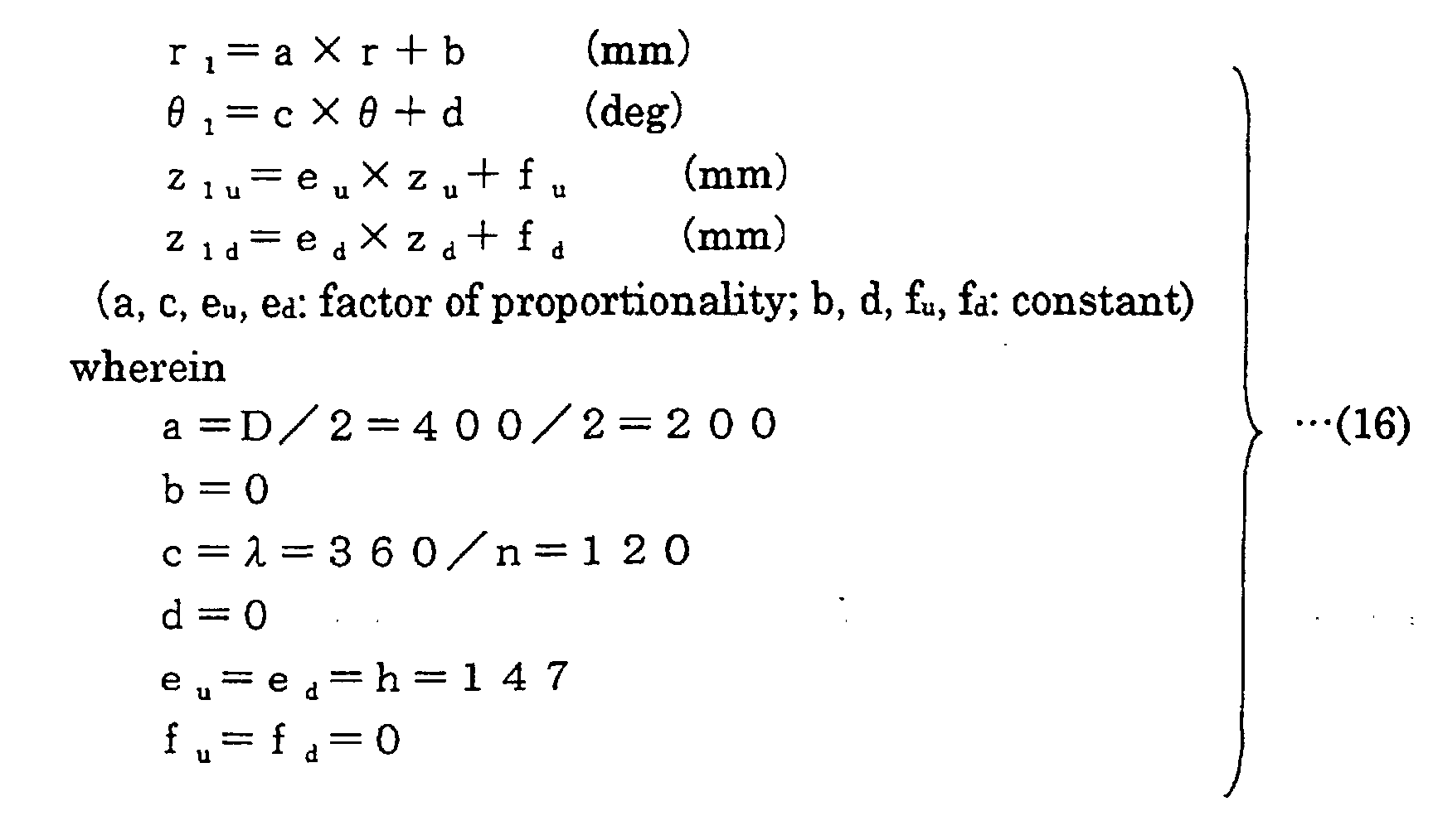
    PUAI Public reference made under article 153(3) epc to a published international application that has entered the european phase

    Free format text: ORIGINAL CODE: 0009012

    17P Request for examination filed

    Effective date: 20020321

    AK Designated contracting states

    Kind code of ref document: A1

    Designated state(s): AT BE CH CY DE DK ES FI FR GB GR IE IT LI LU MC NL PT SE TR

    A4 Supplementary search report drawn up and despatched

    Effective date: 20030618

    RBV Designated contracting states (corrected)

    Designated state(s): AT BE CH DE FR GB LI

    17Q First examination report despatched

    Effective date: 20081113

    GRAP Despatch of communication of intention to grant a patent

    Free format text: ORIGINAL CODE: EPIDOSNIGR1

    RBV Designated contracting states (corrected)

    Designated state(s): DE FR GB

    GRAS Grant fee paid

    Free format text: ORIGINAL CODE: EPIDOSNIGR3

    GRAA (expected) grant

    Free format text: ORIGINAL CODE: 0009210

    AK Designated contracting states

    Kind code of ref document: B1

    Designated state(s): DE FR GB

    REG Reference to a national code

    Ref country code: GB

    Ref legal event code: FG4D

    REF Corresponds to:

    Ref document number: 60141966

    Country of ref document: DE

    Date of ref document: 20100610

    Kind code of ref document: P

    PLBE No opposition filed within time limit

    Free format text: ORIGINAL CODE: 0009261

    STAA Information on the status of an ep patent application or granted ep patent
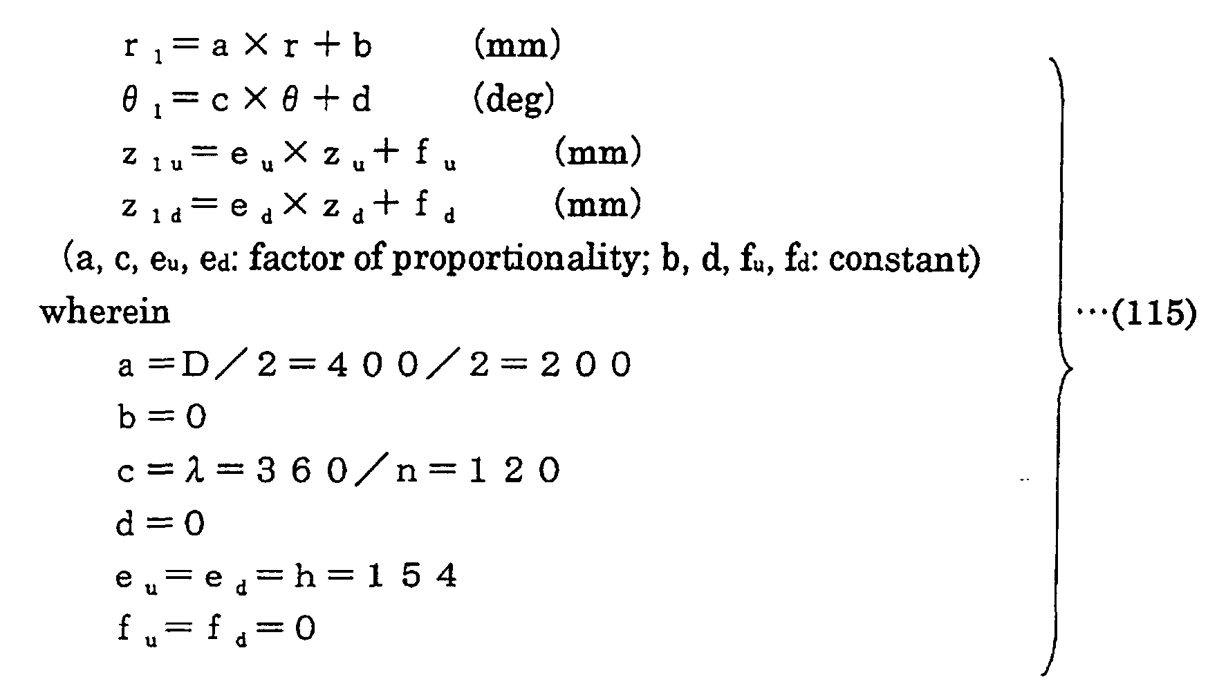
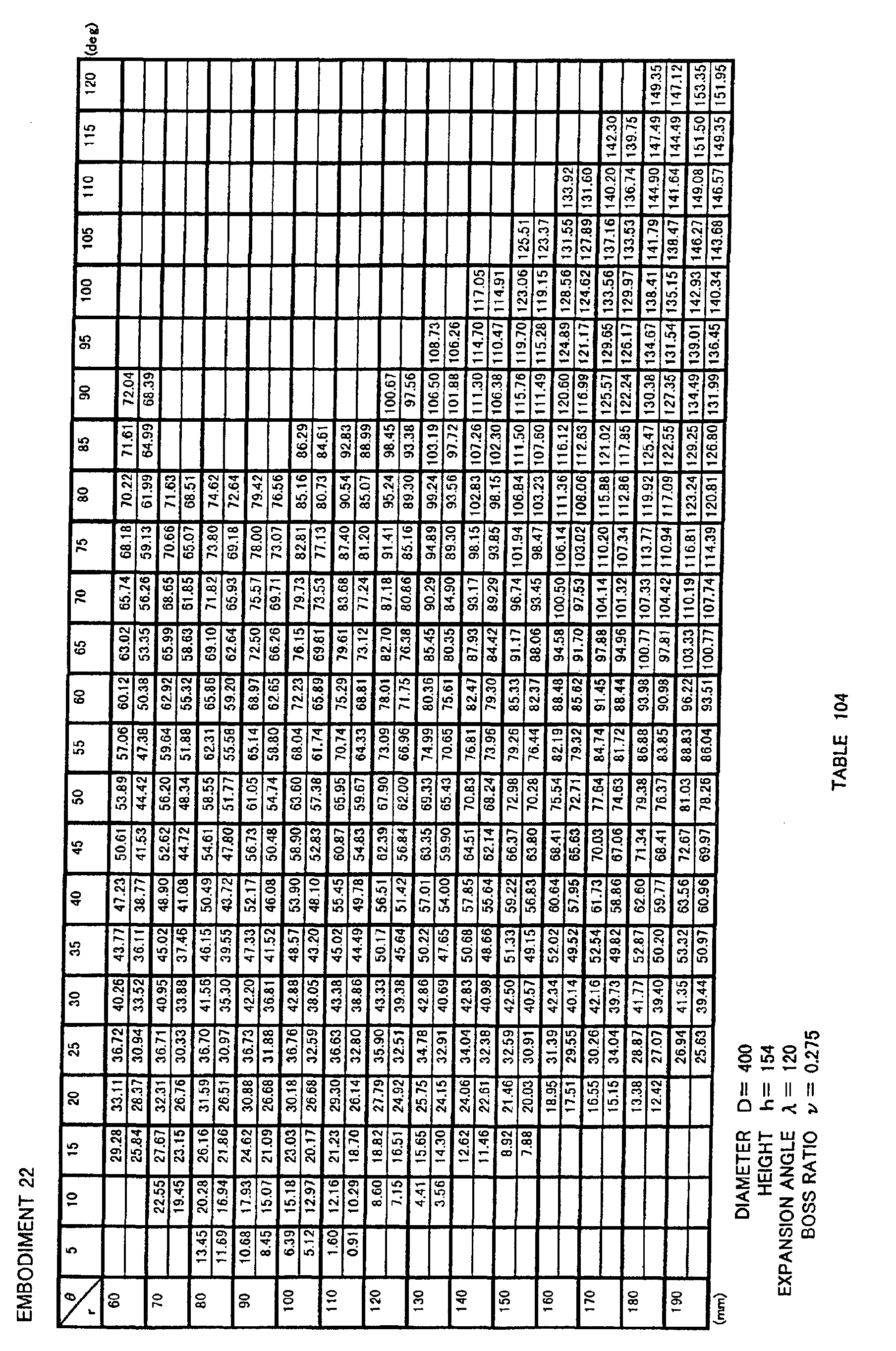
    Free format text: STATUS: NO OPPOSITION FILED WITHIN TIME LIMIT

    26N No opposition filed

    Effective date: 20110131

    REG Reference to a national code

    Ref country code: DE

    Ref legal event code: R084

    Ref document number: 60141966

    Country of ref document: DE

    REG Reference to a national code

    Ref country code: GB

    Ref legal event code: 746

    Effective date: 20140918

    REG Reference to a national code

    Ref country code: DE

    Ref legal event code: R084

    Ref document number: 60141966

    Country of ref document: DE

    Effective date: 20141002

    REG Reference to a national code

    Ref country code: FR

    Ref legal event code: PLFP

    Year of fee payment: 16

    REG Reference to a national code

    Ref country code: FR

    Ref legal event code: PLFP

    Year of fee payment: 17

    REG Reference to a national code

    Ref country code: FR

    Ref legal event code: PLFP

    Year of fee payment: 18

    PGFP Annual fee paid to national office [announced via postgrant information from national office to epo]

    Ref country code: DE

    Payment date: 20190719

    Year of fee payment: 19

    Ref country code: FR

    Payment date: 20190719

    Year of fee payment: 19

    PGFP Annual fee paid to national office [announced via postgrant information from national office to epo]

    Ref country code: GB

    Payment date: 20190719

    Year of fee payment: 19

    REG Reference to a national code

    Ref country code: DE

    Ref legal event code: R119

    Ref document number: 60141966

    Country of ref document: DE

    GBPC Gb: european patent ceased through non-payment of renewal fee

    Effective date: 20200703

    PG25 Lapsed in a contracting state [announced via postgrant information from national office to epo]

    Ref country code: GB

    Free format text: LAPSE BECAUSE OF NON-PAYMENT OF DUE FEES

    Effective date: 20200703

    Ref country code: FR

    Free format text: LAPSE BECAUSE OF NON-PAYMENT OF DUE FEES

    Effective date: 20200731

    PG25 Lapsed in a contracting state [announced via postgrant information from national office to epo]

    Ref country code: DE

    Free format text: LAPSE BECAUSE OF NON-PAYMENT OF DUE FEES

    Effective date: 20210202