EP1298093A1 - Water treating method, water treating apparatus, and hydroponic system using the same - Google Patents
Water treating method, water treating apparatus, and hydroponic system using the same Download PDFInfo
- Publication number
- EP1298093A1 EP1298093A1 EP01941199A EP01941199A EP1298093A1 EP 1298093 A1 EP1298093 A1 EP 1298093A1 EP 01941199 A EP01941199 A EP 01941199A EP 01941199 A EP01941199 A EP 01941199A EP 1298093 A1 EP1298093 A1 EP 1298093A1
- Authority
- EP
- European Patent Office
- Prior art keywords
- water
- conductor
- electrodes
- treated
- treatment step
- Prior art date
- Legal status (The legal status is an assumption and is not a legal conclusion. Google has not performed a legal analysis and makes no representation as to the accuracy of the status listed.)
- Granted
Links
Images



Classifications
-
- C—CHEMISTRY; METALLURGY
- C02—TREATMENT OF WATER, WASTE WATER, SEWAGE, OR SLUDGE
- C02F—TREATMENT OF WATER, WASTE WATER, SEWAGE, OR SLUDGE
- C02F1/00—Treatment of water, waste water, or sewage
- C02F1/46—Treatment of water, waste water, or sewage by electrochemical methods
- C02F1/461—Treatment of water, waste water, or sewage by electrochemical methods by electrolysis
- C02F1/467—Treatment of water, waste water, or sewage by electrochemical methods by electrolysis by electrochemical disinfection; by electrooxydation or by electroreduction
-
- A—HUMAN NECESSITIES
- A61—MEDICAL OR VETERINARY SCIENCE; HYGIENE
- A61L—METHODS OR APPARATUS FOR STERILISING MATERIALS OR OBJECTS IN GENERAL; DISINFECTION, STERILISATION OR DEODORISATION OF AIR; CHEMICAL ASPECTS OF BANDAGES, DRESSINGS, ABSORBENT PADS OR SURGICAL ARTICLES; MATERIALS FOR BANDAGES, DRESSINGS, ABSORBENT PADS OR SURGICAL ARTICLES
- A61L2/00—Disinfection or sterilisation of materials or objects, in general; Accessories therefor
- A61L2/02—Disinfection or sterilisation of materials or objects, in general; Accessories therefor using physical processes
- A61L2/03—Electric current
- A61L2/035—Electrolysis
-
- C—CHEMISTRY; METALLURGY
- C02—TREATMENT OF WATER, WASTE WATER, SEWAGE, OR SLUDGE
- C02F—TREATMENT OF WATER, WASTE WATER, SEWAGE, OR SLUDGE
- C02F1/00—Treatment of water, waste water, or sewage
- C02F1/46—Treatment of water, waste water, or sewage by electrochemical methods
- C02F1/4604—Treatment of water, waste water, or sewage by electrochemical methods for desalination of seawater or brackish water
-
- C—CHEMISTRY; METALLURGY
- C02—TREATMENT OF WATER, WASTE WATER, SEWAGE, OR SLUDGE
- C02F—TREATMENT OF WATER, WASTE WATER, SEWAGE, OR SLUDGE
- C02F1/00—Treatment of water, waste water, or sewage
- C02F1/46—Treatment of water, waste water, or sewage by electrochemical methods
- C02F1/469—Treatment of water, waste water, or sewage by electrochemical methods by electrochemical separation, e.g. by electro-osmosis, electrodialysis, electrophoresis
- C02F1/4691—Capacitive deionisation
-
- C—CHEMISTRY; METALLURGY
- C02—TREATMENT OF WATER, WASTE WATER, SEWAGE, OR SLUDGE
- C02F—TREATMENT OF WATER, WASTE WATER, SEWAGE, OR SLUDGE
- C02F2303/00—Specific treatment goals
- C02F2303/04—Disinfection
Definitions
- the present invention relates to a method and an apparatus for sterilizing water for eating and drinking, waste water discharged from a hydroponic system/fish hatchery, and the like.
- a method has conventionally been employed which cleans up water by disposing a porous filter material capable of collecting the microbes in a running water channel, and securely capturing the microbes in the filter material.
- electrodes are inserted into water for eating and drinking to perform electrolysis, whereby chlorine or ozone is generated, and by its sterilizing function, the microbes contained in water for eating and drinking are killed.
- crops planted in a cultivation bed have been properly grown by circulating a nutrient liquid prepared by dissolving fertilizer and manure in water at a rate suitable for crop cultivation to the cultivation bed.
- the interior of the cultivation bet to which the nutrient liquid has been circulated is an environment suitable for the propagation of pathogenic fungi such as fusarium fungi (a kind of mold). If the propagation of fusarium fungi occurs in the cultivation bed, crop roots are damaged, which kills the crops.
- a device which is constructed to sterilize pathogenic fungi contained in the nutrient liquid by heating the nutrient liquid with a heater, or by ultraviolet rays or ozone contained in a light-transmissive jacket in the circulation channel of the nutrient liquid.
- the above filter material receives and collects the microbes in fine holes formed on its surface. Accordingly, the microbes cannot securely be captured unless the microbes clash on the surface of the filter material or pass through its vicinity. Consequently, a limitation has been placed on the effect of securely capturing the microbes.
- the microbes are securely captured in such a filter material as described above, a saturation state is reached in sooner or later to discharge the microbes into the running water channel. Accordingly, it can be contrived that the securely captured microbes are killed by heating the filter material, but some microbes have resistance to heat, and hence, to assure the effect of sterilization, the filter material must be heated to a relatively high temperature.
- the nutrient liquid has been heated to sterilize the pathogenic fungi propagated in the cultivation bed in the hydroponic system, but since the plants are killed if the heated nutrient liquid is directly used as it is, a cooling device is necessary to cool the heated nutrient liquid. Consequently, there has been a problem that a large amount of energy must be used to heat and cool the nutrient liquid. Furthermore, when the pathogenic fungi contained in the nutrient liquid is sterilized by using ultraviolet rays or ozone, there has been another problem that the concentrations of iron and manganese contained in the nutrient liquid decrease.
- the present invention has been developed to solve the foregoing conventional technical problems, and objects of the present invention are to provide a method and an apparatus for water treatment which can greatly improve the effect of removing microbes contained in water for eating and drinking or waste water, and a hydroponic system using the same.
- a method for water treatment comprising a first treatment step of dipping a pair of electrodes and a conductor capable of collecting at least microbes in a running channel of water to be treated, and applying a positive potential to the conductor and applying negative potentials to the electrodes to adsorb the microbes on the conductor; a second treatment step of stopping the flow of the water to be treated after an end of the first treatment step, and increasing the potentials applied to the conductor and the electrodes to start the electrolysis of the water to be treated while the polarities of the potentials applied to the conductor and the electrodes are maintained intact in the presence of the water to be treated; and a third treatment step of stopping the application of the potential to the conductor after an end of the second treatment step, and applying a positive potential to one of the pair of electrodes and applying a negative potential to the other of the electrodes in the presence of the water to be treated.
- a method for water treatment comprising a first treatment step of dipping a pair of electrodes and a conductor capable of collecting at least microbes in a running channel of water to be treated, and applying a positive potential to the conductor and applying negative potentials to the electrodes to adsorb the microbes on the conductor; a second treatment step of stopping the flow of the water to be treated after an end of the first treatment step, reversing the polarities of the potentials applied to the conductor and the electrodes in the presence of the water to be treated, and increasing the potentials applied to the conductor and the electrodes to start the electrolysis of the water to be treated; and a third treatment step of stopping the application of the potential to the conductor after an end of the second treatment step, and applying a positive potential to one of the pair of electrodes and applying a negative potential to the other of the electrodes in the presence of the water to be treated.
- an apparatus for water treatment comprising a pair of electrodes dipped in a running channel of water to be treated; a conductor dipped in the running channel of the water to be treated, the conductor being capable of collecting at least microbes; and a controller capable of controlling the application of potentials to each of the electrodes and the conductor, and capable of controlling the flow of the water to be treated.
- the controller executes a first treatment step of applying a positive potential to the conductor in a flow state of the water to be treated, and negative potentials to the electrodes to adsorb the microbes on the conductor, a second treatment step of stopping the flow of the water to be treated after an end of the first treatment step, and increasing the potentials applied to the conductor and the electrodes to start the electrolysis of the water to be treated while the polarities of the potentials applied to the conductor and the electrodes are maintained intact in the presence of the water to be treated, and a third treatment step of stopping the application of the potential to the conductor after an end of the second treatment step, and applying a positive potential to one of the pair of electrodes and applying a negative potential to the other of the electrodes in the presence of the water to be treated.
- an apparatus for water treatment comprising a pair of electrodes dipped in a running channel of water to be treated; a conductor dipped in the running channel of the water to be treated, the conductor being capable of collecting at least microbes; and a controller capable of controlling the application of potentials to each of the electrodes and the conductor, and capable of controlling the flow of the water to be treated.
- the controller executes a first treatment step of applying a positive potential to the conductor in a flow state of the water to be treated, and negative potentials to the electrodes to adsorb the microbes on the conductor, a second treatment step of stopping the flow of the water to be treated after an end of the first treatment step, reversing polarities applied to the conductor and the electrodes in the presence of the water to be treated, and increasing the potentials applied to the conductor and the electrodes to start the electrolysis of the water to be treated, and a third treatment step of stopping the application of the potential to the conductor after an end of the second treatment step, and applying a positive potential to one of the pair of electrodes and applying a negative potential to the other of the electrodes in the presence of the water to be treated.
- the method or the apparatus for water treatment of the present invention further comprises a treatment step of discharging the water to be treated, in which the conductor and the electrodes are dipped, after an end of the third treatment step.
- the conductor is a porous body.
- the conductor is made of a carbon fiber.
- the carbon fiber of the conductor includes precious metal added thereto, the precious metal being one selected from palladium, platinum, iridium, and tantalum.
- chlorine and/or ozone is generated at one of the pair of electrodes, and active oxygen is generated at the other of the electrodes.
- each of the electrodes includes precious metal added thereto, the precious metal being one selected from palladium, platinum, iridium, and tantalum.
- a hydroponic system for cultivating plants by supplying a nutrient liquid to a cultivation bed, comprising a path for recirculating a secondary nutrient liquid discharged from the cultivation bed to the same cultivation bed; and the foregoing water treatment apparatus provided in the path.
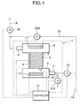
- FIG. 1 is a block diagram showing an apparatus 1 for water treatment according to an embodiment of the present invention.
- This water treatment apparatus 1 comprises: an inlet side header 3 including an inlet 2 for introducing water to be treated, such as water for eating and drinking, stored in a reservoir, or water discharged from a hydroponic system; an outlet side header 6 including an outlet 4 for discharging the water to be treated; a housing portion 7 provided to communicate the headers 3 and 6 with each other; a carbon fiber 8 housed without any gaps in the housing portion 7; a current-carrying terminal 9 provided in the carbon fiber 8; an electrode 11 provided in the header 3 and disposed away from the carbon fiber 8; and an electrode 12 provided in the header 6 and disposed away from the carbon fiber 8.
- the inlet 2 and the outlet 4 are connected into a water supply system 14 from a water pipe or the like from the reservoir.
- a valve 16 is provided in the water supply system 14 before the inlet 2.
- a running water valve 22 is connected to the water supply system 14 downstream of the outlet 4, and a bypass pipe 20 is connected to the water supply system 14.
- the bypass pipe 20 is connected to the upstream side of the valve 16 and between the outlet 4 and the running water valve 22.
- a bypass valve 20A is provided in the bypass pipe 20.
- a drain pipe 21 including a drain valve 21A is connected between the inlet 2 and the valve 16, and the end part of this drain pipe 21 is communicated with a drain ditch (not shown).
- a reference numeral 17 denotes a controller provided to control the application of potentials to the current-carrying terminal 9 and the electrodes 11 and 12, and the opening/closing of the valve 16, the bypass valve 20A, the drain valve 21A, and the running water valve 22.
- the carbon fiber 8 is a porous conductor, which serves as a filter for the water to be treated, disposed in the water treatment apparatus 1.
- Each of the current-carrying terminal 9, and the electrodes 11 and 12 (making a pair sandwiching the carbon fiber 8) contains precious metal added at least to its surface, the precious metal being one selected from palladium (Pd), platinum (Pt), iridium (Ir), tantalum (Ta), etc.
- the water treatment apparatus 1 is connected, for example, into the water supply system 14 for water for eating and drinking as shown in FIG. 1.
- the controller 17 is composed of, for example, a general-purpose microcomputer, which sequentially executes the following first to fourth treatment steps in accordance with preset programs.
- the controller 17 first closes the bypass valve 20A and the drain valve 21A, and opens the valve 16 and the running water valve 22. Accordingly, water to be treated flows through the inlet 2 into the header 3 of the water treatment apparatus 1. After filling the header 3, the water to be treated reaches the carbon fiber 8, and then flows through the inside into the header 6. After filling the header 6, the water to be treated flows out through the outlet 4. Thus, the electrodes 11 and 12, and the carbon fiber 8 are dipped in the water to be treated. Microbes such as bacteria, mold or the like are captured in very small holes formed in the surface of the carbon fiber 8 during their passage through the same. Alternatively, the microbes are captured by affinity between the carbon fiber 8 and the microbes, or the filter function of the carbon fiber 8, and secured.
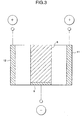
- the controller 17 applies a positive potential (+) to the current-carrying terminal 9 of the carbon fiber 8, and negative potentials (-) to the electrodes 11 and 12.
- the potentials applied in this case are at levels not causing any water electrolysis, and decided according to the quality or the like of the water to be treated.
- the water to be treated fills portions between the electrodes 11 and 12 and the carbon fiber 8 in Fig.2.
- the microbes are attracted to the carbon fiber 8 set at the positive potential. Accordingly, the microbes that have entered the carbon fiber 8 are attracted to the surface of the carbon fiber 8, and secured in the very small holes thereof smoothly and efficiently.
- the water to be treated passed through the water treatment apparatus 1 and discharged through the outlet 4, becomes normal water for eating and drinking, from which the microbes have been secured to the carbon fiber 8 and removed.
- This first treatment step is executed during a period when it is necessary to supply water for eating and drinking (e.g., in the running water channel of the embodiment, during a period when a faucet is open to supply water. In the later-described reservoir, the treatment step is executed for a predetermined period).
- the controller 17 executes the second treatment step.
- the controller 17 closes the valve 16 and the running water valve 22. Accordingly, the water to be treated stays in the headers 3 and 6 and the carbon fiber 8 of the water treatment apparatus 1. In this state, the controller 17 increases a potential applied to the current-carrying terminal 9 of the carbon terminal 8 to start the electrolysis of the water to be treated while maintaining intact the polarities of potentials applied to the current-carrying terminal 9 of the carbon fiber 8, and the electrodes 11 and 12.
- the potentials applied in this case are also decided according to the quality or the like of the water to be treated. It is also assumed that the water to be treated fills portions between the electrodes 11 and 12 and the carbon fiber 8 of FIG. 2
- pH of the water to be treated is reduced in the vicinity of the surface of the carbon fiber 8, for example becoming an acid of about pH 2.
- optimum pH of microbes is generally around pH 7
- metabolic disorder occurs in the microbes in the water to be treated, deviated from the optimum pH, greatly reducing proliferation and heat resistance.
- the microbes secured to the carbon fiber 8 are surrounded with acid water, a great reduction occurs in the heat resistance of the microbes, which normally has heat resistance up to +60°C.
- hypochlorous acid may be generated in the second treatment step, sterilization by this hypochlorous acid is carried out to a certain extent.
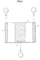
- the following second treatment step A is executed by reversing the potentials applied to the carbon fiber 8 and the electrodes 11 and 12 after the end of the first treatment step.
- the controller 17 applies a negative potential (-) to the current-carrying terminal 9 of the carbon fiber 8, and positive potentials (+) to the electrodes 11 and 12 as shown in FIG. 3.
- the potentials applied in this case are also decided according to the quality or the like of the water to be treated.
- the water to be treated fills portions between the electrodes 11 and 12 and the carbon fiber 8.
- the carbon fiber 8 After the carbon fiber 8 is set at the negative potential, pH of the water to be treated is increased in the vicinity of the surface of the carbon fiber 8, for example becoming alkaline of about pH 11. Accordingly, since the microbes secured to the carbon fiber 8 is surrounded with alkaline water, protein of microbes such as protozoa is denatured/dissolved, reducing heat resistance thereof. Thus, in the second treatment step (including the second treatment step A, hereinafter), the effect of sterilization to be executed next is improved. Then, the controller 17 executes the third treatment step after carrying out the electrolysis of the water to be treated for a predetermined time.
- the controller 17 stops the application of the potential to the carbon fiber 8, and applies a positive potential to one of the electrodes 11 and 12, and applies a negative potential to the other (in this case, no positive or negative potentials are applied to the current-carrying terminal 9). Accordingly, currents flow to the water to be treated and the carbon fiber 8 between the electrodes 11 and 12 to generate heat from the carbon fiber and the water to be treated. At this time, the temperatures of the carbon fiber 8 and the water to be treated are increased at least to about +50°C. Because of the temperature increase caused by the generated heat, the microbes secured to the carbon fiber 8 in the first treatment step, and left and reduced for the heat resistance in the second treatment step are also killed efficiently in the third treatment step. Since the water to be treated is subjected to electrolysis to reduce/increase pH, even microbes that normally have heat resistance up to +60°C can be killed at a low temperature of about +50°C.
- the electrolysis of the water to be treated is started at each of the electrodes 11 and 12, and the electrode is set at a positive potential.
- the electrode 12 as an anode electrode, chlorine ions contained in the water to be treated emit electrons to generate chlorine (or hypochlorous acid). Water molecules are also decomposed, and coupled with oxygen atoms to generate ozone.
- the electrode 11 set at a negative potential to become a cathode electrode active oxygen is generated.
- voltages applied to the electrodes 11 and 12 ma be DC or AC (commercial AC) voltages.
- the nutrient liquid in both headers 3 and 6 and the housing portion 7 can be heated without causing any polarization on the electrodes.
- the microbes having the heat resistance reduced by the electrolysis can be killed more efficiently.
- a DC voltage is applied between the electrodes 11 and 12, or between the electrodes 11 and 12 and the carbon fiber 8, to generate heat, thus killing the microbes, with the DC voltage, water electrolysis occurs in addition to the foregoing ozone generation, and consequently energy is consumed for other than heat generation.
- each of the electrodes 11 and 12 has precious metal added thereto, which is one selected from palladium, platinum, iridium, tantalum, etc.
- chlorine and/or ozone is actively generated at the electrode 11; and active oxygen at the electrode 11.
- Such chlorine (hypochlorous acid), ozone, and active oxygen can also kill the microbes on the surface of the carbon fiber 8 and in the water to be treated.
- the controller 17 executes the fourth treatment step after the efficient killing of the microbes in the third treatment step.
- the controller 17 opens the bypass valve 20A and the drain pipe 21A while the valve 16 and the running water valve 22 are closed, after the end of the third treatment step. Accordingly, the water to be treated from the water supply system 14 flows through the outlet 4 into the header 6, and passes through the housing portion 7 and the header 3, and then discharges from the drain pipe 21 to the drain ditch.
- the microbes secured to the carbon fiber 8 from the direction of the inlet 2 are easily peeled off from the carbon fiber 8, and discharged through the drain pipe 21 to the drain ditch, by the water to be treated, which flows in from the direction of the outlet 4 and passes. Accordingly, since the carbon fiber 8 can be restored to be an original clean carbon fiber 8, which has no secured microbes, it is possible to maintain the carbon fiber 8 and the electrodes 11 and 12 neat and clean.
- the microbes secured to the carbon fiber 8 are killed in the second and third treatment steps and, in the fourth treatment step, the water to be treated is supplied through the outlet 4 of the water treatment apparatus 1, and discharged through the drain pipe 21 connected between the inlet 2 and the valve 16. Accordingly, since the microbes killed and secured to the carbon fiber 8 can be peeled off, and washed away to the drain ditch, it is possible to achieve a good microbe securing operation by the carbon fiber 8 when a next first treatment step is executed.
- FIG. 6 a secondary nutrient liquid (nutrient liquid with nutrition reduced because of its absorption by a plant in a cultivation bed 35) stored in a nutrient liquid tank 36 is sent out by a circulation pump 37.
- the secondary nutrient liquid flows into a nutrient liquid storage tank 32, and temporarily stored therein.
- the nutrient liquid stored in the nutrient liquid storage tank 32 flows into a cartridge filter 33 composed of a bobbin winder filter. After the refuse left without being removed at the filter tank 31, the nutrient liquid flows through the inlet 2 into the water treatment apparatus 1.
- the nutrient liquid that has entered the water treatment apparatus 1 is subjected to electrolysis, resulting in the adsorption of fungi propagated in the nutrient liquid on the conductor (mainly carbon fiber 8), especially fusarium fungi or other bacteria (referred to as pathogenic fungi, hereinafter) that damages the root of a crop 38 as a plant in the cultivation bet 35.
- pathogenic fungi fusarium fungi or other bacteria
- the nutrient liquid becomes acid water of about pH 2, and the pathogenic fungi adsorbed on the conductor are deviated from the optimum pH, causing metabolic disorder. As a result, proliferation and heat resistance are greatly reduced.
- the process proceeds to the third treatment step, where an commercial AC voltage is applied between the electrodes 11 and 12, or between the electrodes 11 and 12 and the carbon fiber 8.
- the nutrient liquid in both headers 3 and 6 and the housing portion 7 generates heat, thereby heating the pathogenic fungi. Accordingly, the pathogenic fungi that have suffered from metabolic disorder are killed.
- a reference numeral 40 denotes water (in this case, tap water or underground water is used for water).
- the nutrient liquid circulated through the circulation path is absorbed by the crop 38, and reduced in amount by natural evaporation.
- the water treatment apparatus 1 is replenished with the water 40 by an amount equal to the reduced amount of the nutrient liquid.
- a nutrient that is short is selected from fertilizer and manure adjusting devices 34A, 34B, 34C and 34D (in this case, magnesium (Mg), iron (Fe), manganese (Mn), copper (Cu), and other fertilizer and manure (nutrients) expected to become short are separately housed in the fertilizer and manure adjusting devices 34A, 34B, 34C and 34D), and thrown into the nutrient liquid adjustment tank 34.
- fertilizer and manure adjusting devices 34A, 34B, 34C and 34D in this case, magnesium (Mg), iron (Fe), manganese (Mn), copper (Cu), and other fertilizer and manure (nutrients) expected to become short are separately housed in the fertilizer and manure adjusting devices 34A, 34B, 34C and 34D), and thrown into the nutrient liquid adjustment tank 34.
- the nutrient liquid adjustment tank 34 the nutrient liquid is adjusted to one containing a nutrient fit for the growth of the crop 38 planted in the cultivation bed 35. Then, the nutrient liquid adjusted to one containing the nutrient fit for the growth of the plant 38 flows from the nutrient liquid adjustment tank 34 into the cultivation bed 35 having the planted crop 38, and the predetermined amount of the nutrient liquid is absorbed by the crop 38. Subsequently, a secondary nutrient liquid obtained after the reduction of nutrition is discharged to return to the nutrient liquid tank 36, and sent out by the circulation pump 37 again. Accordingly, the nutrient liquid is repeatedly recycled as a recycling liquid.
- the water treatment apparatus 1 is provided in the path of recirculating the secondary nutrient liquid out of the cultivation bed 35 to the same, it is possible to heat the pathogenic fungi contained in the nutrient liquid circulated through the path for the flowing of the nutrient liquid and the secondary nutrient liquid by greatly deviating them from the optimum pH. Accordingly, by causing metabolic disorder in the pathogenic fungi present in the circulation path of the cultivation bed 35, it is possible to perform sterilization by heating and killing the pathogenic fungi suffering from the metabolic disorder. As a result, since the conventional necessity of a large amount of energy for the nutrient liquid heating and sterilization using the heater is eliminated, great energy conservation can be achieved.
- the positive potential (+) was applied to the current-carrying terminal 9 of the carbon fiber 8, and the negative potentials (-) to both electrodes 11 and 12 in the second treatment step.
- the negative potential (-) was applied to the current-carrying terminal 9 of the carbon fiber 8, and the positive potentials (+) to both electrodes 11 and 12.
- the process is not limited to such, and in the second treatment step, the second treatment step and the second treatment step A may be alternatively carried out.
- positive potentials (+) and negative potentials (-) may be alternately applied to the carbon fiber 8 and both electrodes 11 and 12 to kill acid or alkaline microbes of optimum pH. In this case, the present invention is similarly advantageous.
- the water treatment apparatus 1 was provided in the running water channel such as a water pipe from the reservoir. However, there is no limitation in this regard. An advantage is similar even if the water treatment apparatus is directed set in the reservoir or provided in the running channel of discharged water.
- the conductive carbon fiber was used as a conductor.
- fibers other than the carbon fiber 8 can be used as long as they are conductors capable of collecting microbes.
- the current-carrying terminal 9 is disposed roughly in the center of the carbon fiber 8 as shown in FIG. 5, the application of the potential to the carbon fiber 8 is made more uniform. In this case, however, it is necessary to mortgage water flowing by forming the current-carrying terminal 9 in a net shape, or providing a punching hole or the like. In this case, it is assumed that the current-carrying terminal 9 is made of a material similar to those of the electrodes 11 and 12.
- the conductor was described as the conductive carbon fiber 8.
- the conductor may be composed of the current-carrying terminal 9, and a nonconductive filter member such as a porous fiber, cotton, a synthetic fiber or the like.
- a positive potential to the current-carrying terminal 9 of the water treatment apparatus 1 shown in FIG. 5, and negative potentials to both electrodes, the microbes can be attracted to the current-carrying terminal 9, and collected by the filter member. Thereafter, it is only necessary to sequentially carry out the second to fourth treatment steps.
- the water to be treated was supplied through the outlet 4 of the water treatment apparatus 1, and then discharged through the drain pipe 21 connected between the inlet 2 and the valve 16.
- the carbon fiber 8 may be washed by supplying water to be treated through the inlet 2, and then discharging it through the outlet 4.
- the water treatment apparatus 1 of the present invention was provided between the cartridge filter 33 and the nutrient liquid adjustment tank 34 of the hydroponic system 30.
- the water treatment apparatus 1 may be provided anywhere in the circulation path for circulating the nutrient liquid and the secondary nutrient liquid.
- the water treatment apparatus 1 was provided in one place of the hydroponic system 30.
- the water treatment apparatus 1 may be provided in two or more places in the circulation path of the nutrient liquid and the secondary nutrient liquid.
- the microbes contained in the water to be treated are collected by the conductor in the first treatment step.
- the microbes since the microbes have been charged at a negative potential, the microbes are attracted to the conductor charged at a positive potential.
- the securing of the microbes to the conductor is smoothly and efficiently carried out.
- the flow of the water to be treated is stopped, and potentials applied to the conductor and the electrodes are increased to start the electrolysis of the water to be treated while the polarities of the potentials applied to the conductor and the electrodes are maintained intact.
- pH of the water to be treated is increased in the vicinity of the surface of the conductor to become acid, making it possible to greatly deviate pH of the water to be treated around the microbes from the optimum pH of the microbes.
- hypochlorous acid is similarly generated in the surface of the conductor. Since the microbes are metabolized by oxygen, metabolic disorder occurs by the water to be treated, deviated from the optimum pH, greatly reducing proliferation and heat resistance. As a result, the microbes can be killed at a lower temperature increase.
- sterilization is carried out to a certain extent by the hypochlorous acid.
- the application of the potential to the conductor is stopped, and a positive potential is applied to one of the pair of electrodes and a negative potential is applied to the other.
- the water to be treated generates heat.
- the temperature increase caused by such heat generation kills the microbes, which have been secured to the conductor and suffered from the metabolic disorder because of the deviation of the water to be treated from the optimum pH.
- the microbes contained in the water to be treated are collected by the conductor in the first treatment step.
- the microbes since the microbes have been charged at a negative potential, the microbes are attracted to the conductor charged at a positive potential.
- the securing of the microbes to the conductor is smoothly and efficiently carried out.
- the flow of the water to be treated is stopped, the polarities of the potentials applied to the conductor and the electrodes are reversed, and potentials applied to the conductor and the electrodes are increased to start the electrolysis of the water to be treated.
- pH of the water to be treated is increased in the vicinity of the surface of the conductor to become alkaline, making it possible to greatly deviate pH of the water to be treated around the microbes from the optimum pH of the microbes. Since the microbes are metabolized by oxygen, metabolic disorder occurs by the water to be treated, deviated from the optimum pH, greatly reducing proliferation and heat resistance.
- third treatment step is executed. Specifically, the application of the potential to the conductor is stopped, and a positive potential is applied to one of the pair of electrodes and a negative potential is applied to the other.
- the water to be treated generates heat.
- the temperature increase caused by such heat generation kills the microbes, which have been secured to the conductor and suffered from the metabolic disorder because of the deviation of the water to be treated from the optimum pH.
- the microbes that have been collected by conductor and killed can be washed away.
- the water to be treated, in which the conductor and the electrodes have been dipped, is discharged, the microbes stuck to the conductor and the electrodes can be easily peeled off by the discharged treated water. As a result, it is possible to maintain the conductor and the electrodes neat and clean.
- the conductor is a porous body, it is possible to greatly improve the effect of collecting the microbes.
- the conductor is made of a carbon fiber in addition, it is possible to greatly deviate pH of the water to be treated from the optimum pH of the microbes in the connecting effect of the microbes of the first treatment step and the electrolysis of the second treatment step.
- the carbon fiber constituting the conductor in addition to the above includes the added precious metal, which is one selected from palladium, platinum, iridium and tantalum.
- the added precious metal which is one selected from palladium, platinum, iridium and tantalum.
- chlorine and/or ozone is generated at one of the electrodes, and active oxygen at the other.
- each of the electrodes includes the added precious metal, which is one selected from palladium, platinum, iridium, and tantalum.
- the added precious metal which is one selected from palladium, platinum, iridium, and tantalum.
- plant cultivation is carried out by supplying the nutrient liquid to the cultivation bed, the path is provided to recirculate the secondary nutrient liquid out of the cultivation bed to the same, and the foregoing water treatment apparatus is provided in this path.
- the pathogenic fungi by greatly deviating the optimum pH of the pathogenic fungi present in the recirculation path of the cultivation bed to cause metabolic disorder, and then heating the pathogenic fungi.
- a large amount of energy for, for example the conventional sterilization carried out by heating the nutrient liquid is made unnecessary.
- the pathogenic fungi in the cultivation bed can be greatly reduced with less energy, it is possible to achieve great energy conservation.
- the pathogenic fungi propagated in the nutrient liquid are not sterilized by using any fungicide or ultraviolet rays, which was carried out, for example in the conventional case, it is possible to suppress reductions in the concentrations of iron and manganese contained in the nutrient liquid, and improve the effect of removing the pathogenic fungi in the recirculation path.
- the present invention enables a clean and hygienic plant to be grown.
Landscapes
- Life Sciences & Earth Sciences (AREA)
- Health & Medical Sciences (AREA)
- Chemical & Material Sciences (AREA)
- Water Supply & Treatment (AREA)
- Chemical Kinetics & Catalysis (AREA)
- Hydrology & Water Resources (AREA)
- Engineering & Computer Science (AREA)
- Environmental & Geological Engineering (AREA)
- Electrochemistry (AREA)
- Organic Chemistry (AREA)
- General Chemical & Material Sciences (AREA)
- Epidemiology (AREA)
- Animal Behavior & Ethology (AREA)
- General Health & Medical Sciences (AREA)
- Public Health (AREA)
- Veterinary Medicine (AREA)
- Water Treatment By Electricity Or Magnetism (AREA)
- Hydroponics (AREA)
- Treatment Of Water By Oxidation Or Reduction (AREA)
Abstract
Description
Claims (11)
- A method for water treatment comprising:a first treatment step of dipping a pair of electrodes and a conductor capable of collecting at least microbes in a running channel of water to be treated, and applying a positive potential to the conductor and applying negative potentials to the electrodes to adsorb the microbes on the conductor;a second treatment step of stopping the flow of the water to be treated after an end of the first treatment step, and increasing the potentials applied to the conductor and the electrodes to start the electrolysis of the water to be treated while the polarities of the potentials applied to the conductor and the electrodes are maintained intact in the presence of the water to be treated; anda third treatment step of stopping the application of the potential to the conductor after an end of the second treatment step, and applying a positive potential to one of the pair of electrodes and applying a negative potential to the other of the electrodes in the presence of the water to be treated.
- A method for water treatment comprising:a first treatment step of dipping a pair of electrodes and a conductor capable of collecting at least microbes in a running channel of water to be treated, and applying a positive potential to the conductor and applying negative potentials to the electrodes to adsorb the microbes on the conductor;a second treatment step of stopping the flow of the water to be treated after an end of the first treatment step, reversing the polarities of the potentials applied to the conductor and the electrodes in the presence of the water to be treated, and increasing the potentials applied to the conductor and the electrodes to start the electrolysis of the water to be treated; anda third treatment step of stopping the application of the potential to the conductor after an end of the second treatment step, and applying a positive potential to one of the pair of electrodes and applying a negative potential to the other of the electrodes in the presence of the water to be treated.
- An apparatus for water treatment comprising:wherein the controller executes a first treatment step of applying a positive potential to the conductor in a flow state of the water to be treated, and negative potentials to the electrodes to adsorb the microbes on the conductor, a second treatment step of stopping the flow of the water to be treated after an end of the first treatment step, and increasing the potentials applied to the conductor and the electrodes to start the electrolysis of the water to be treated while the polarities of the potentials applied to the conductor and the electrodes are maintained intact in the presence of the water to be treated, and a third treatment step of stopping the application of the potential to the conductor after an end of the second treatment step, and applying a positive potential to one of the pair of electrodes and applying a negative potential to the other of the electrodes in the presence of the water to be treated.a pair of electrodes dipped in a running channel of water to be treated;a conductor dipped in the running channel of the water to be treated, the conductor being capable of collecting at least microbes; anda controller capable of controlling the application of potentials to each of the electrodes and the conductor, and capable of controlling the flow of the water to be treated,
- An apparatus for water treatment comprising:wherein the controller executes a first treatment step of applying a positive potential to the conductor in a flow state of the water to be treated, and negative potentials to the electrodes to adsorb the microbes on the conductor, a second treatment step of stopping the flow of the water to be treated after an end of the first treatment step, reversing polarities applied to the conductor and the electrodes in the presence of the water to be treated, and increasing the potentials applied to the conductor and the electrodes to start the electrolysis of the water to be treated, and a third treatment step of stopping the application of the potential to the conductor after an end of the second treatment step, and applying a positive potential to one of the pair of electrodes and applying a negative potential to the other of the electrodes in the presence of the water to be treated.a pair of electrodes dipped in a running channel of water to be treated;a conductor dipped in the running channel of the water to be treated, the conductor being capable of collecting at least microbes; anda controller capable of controlling the application of potentials to each of the electrodes and the conductor, and capable of controlling the flow of the water to be treated,
- A method or an apparatus for water treatment according to any one of claims 1 to 4, further comprising a treatment step of discharging the water to be treated, in which the conductor and the electrodes are dipped, after an end of the third treatment step.
- A method or an apparatus for water treatment according to any one of claims 1 to 5, wherein the conductor is a porous body.
- A method or an apparatus for water treatment according to any one of claims 1 to 6, wherein the conductor is made of a carbon fiber.
- A method or an apparatus for water treatment according to claim 7, wherein the carbon fiber of the conductor includes precious metal added thereto, the precious metal being one selected from palladium, platinum, iridium, and tantalum.
- A method or an apparatus for water treatment according to any one of claims 1 to 8, wherein in the third treatment step, chlorine and/or ozone is generated at one of the pair of electrodes, and active oxygen is generated at the other of the electrodes.
- A method or an apparatus for water treatment according to any one of claims 1 to 9, wherein each of the electrodes includes precious metal added thereto, the precious metal being one selected from palladium, platinum, iridium, and tantalum.
- A hydroponic system for cultivating plants by supplying a nutrient liquid to a cultivation bed, comprising:a path for recirculating a secondary nutrient liquid discharged from the cultivation bed to the same cultivation bed; anda water treatment apparatus provided in the path, the water treatment apparatus being specified in any one of claims 3 to 10.
Applications Claiming Priority (5)
| Application Number | Priority Date | Filing Date | Title |
|---|---|---|---|
| JP2000191731 | 2000-06-26 | ||
| JP2000191731 | 2000-06-26 | ||
| JP2000332849A JP3296812B2 (en) | 2000-06-26 | 2000-10-31 | Water treatment method, water treatment apparatus and hydroponic cultivation system using the same |
| JP2000332849 | 2000-10-31 | ||
| PCT/JP2001/005386 WO2002000554A1 (en) | 2000-06-26 | 2001-06-25 | Water treating method, water treating apparatus, and hydroponic system using the same |
Publications (3)
| Publication Number | Publication Date |
|---|---|
| EP1298093A1 true EP1298093A1 (en) | 2003-04-02 |
| EP1298093A4 EP1298093A4 (en) | 2004-05-06 |
| EP1298093B1 EP1298093B1 (en) | 2005-11-02 |
Family
ID=26594701
Family Applications (1)
| Application Number | Title | Priority Date | Filing Date |
|---|---|---|---|
| EP01941199A Expired - Lifetime EP1298093B1 (en) | 2000-06-26 | 2001-06-25 | Water treating method, water treating apparatus, and hydroponic system using the same |
Country Status (4)
| Country | Link |
|---|---|
| US (1) | US6814853B2 (en) |
| EP (1) | EP1298093B1 (en) |
| JP (1) | JP3296812B2 (en) |
| WO (1) | WO2002000554A1 (en) |
Families Citing this family (22)
| Publication number | Priority date | Publication date | Assignee | Title |
|---|---|---|---|---|
| JP3568487B2 (en) * | 2001-04-11 | 2004-09-22 | 三洋電機株式会社 | Water treatment method, water treatment device and hydroponic cultivation system using the same |
| US6994706B2 (en) | 2001-08-13 | 2006-02-07 | Minnesota Medical Physics, Llc | Apparatus and method for treatment of benign prostatic hyperplasia |
| WO2004066716A1 (en) * | 2003-01-29 | 2004-08-12 | Seoul National University Industry Foundation | Nutrient-flow wick culture system for potted plants and cultivation method thereby |
| KR100542895B1 (en) | 2003-12-22 | 2006-01-11 | 재단법인 포항산업과학연구원 | Electrolytic ballast water treatment method and treatment apparatus using sodium hypochlorite |
| JP4552219B2 (en) * | 2005-08-15 | 2010-09-29 | 幸英 松本 | Method for adjusting culture medium for hydroponics and method for supplying trace elements |
| JP2008307524A (en) * | 2007-05-14 | 2008-12-25 | Sanyo Electric Co Ltd | Water treatment device |
| CN101980968B (en) * | 2008-03-25 | 2012-10-31 | 棚氏处理有限公司 | Portable hardness adjustment device for adjusting the hardness of drinking water |
| US20110108437A1 (en) * | 2008-06-23 | 2011-05-12 | Tanah Process Ltd. | Disinfection method and disinfection device |
| US8632534B2 (en) | 2009-04-03 | 2014-01-21 | Angiodynamics, Inc. | Irreversible electroporation (IRE) for congestive obstructive pulmonary disease (COPD) |
| US8903488B2 (en) | 2009-05-28 | 2014-12-02 | Angiodynamics, Inc. | System and method for synchronizing energy delivery to the cardiac rhythm |
| US9895189B2 (en) | 2009-06-19 | 2018-02-20 | Angiodynamics, Inc. | Methods of sterilization and treating infection using irreversible electroporation |
| JP5308247B2 (en) * | 2009-06-19 | 2013-10-09 | 地方独立行政法人大阪府立環境農林水産総合研究所 | Hydroponic cultivation equipment and hydroponic cultivation method |
| WO2012051433A2 (en) | 2010-10-13 | 2012-04-19 | Angiodynamics, Inc. | System and method for electrically ablating tissue of a patient |
| KR101212752B1 (en) * | 2010-10-21 | 2013-01-02 | (주) 아쿠아캐어코리아 | Clean water treatment system of cultivating water the pulse family and gramineae plant |
| JP5787439B2 (en) * | 2011-06-13 | 2015-09-30 | 株式会社アクト | Waste liquid treatment equipment and cleaning system |
| US9414881B2 (en) | 2012-02-08 | 2016-08-16 | Angiodynamics, Inc. | System and method for increasing a target zone for electrical ablation |
| JP6361274B2 (en) * | 2014-05-14 | 2018-07-25 | 栗田エンジニアリング株式会社 | Culture medium purification method and purification apparatus |
| US12114911B2 (en) | 2014-08-28 | 2024-10-15 | Angiodynamics, Inc. | System and method for ablating a tissue site by electroporation with real-time pulse monitoring |
| JP6551731B2 (en) * | 2015-04-30 | 2019-07-31 | 国立大学法人島根大学 | Hydroponic cultivation method, electrolysis apparatus for hydroponic cultivation |
| US10905492B2 (en) | 2016-11-17 | 2021-02-02 | Angiodynamics, Inc. | Techniques for irreversible electroporation using a single-pole tine-style internal device communicating with an external surface electrode |
| US11939244B2 (en) * | 2019-05-08 | 2024-03-26 | University Of Guelph | Treatment of fertigation water |
| US20240092661A1 (en) * | 2022-09-19 | 2024-03-21 | Kohler Co. | Disinfection of water using pulsed electric fields |
Family Cites Families (7)
| Publication number | Priority date | Publication date | Assignee | Title |
|---|---|---|---|---|
| DE2442474A1 (en) * | 1974-09-05 | 1976-03-18 | Sachs Systemtechnik Gmbh | MULTIPLE-PLATE CELL FOR DISINFECTION AND DETOXIFICATION OF LIQUIDS USING ANODIC OXYDATION |
| JPS5499340A (en) * | 1977-09-21 | 1979-08-06 | Inst Biomedizinische Technik | Method and device for pasteurizing fluid by anodic oxidation |
| JPH044822A (en) * | 1990-04-20 | 1992-01-09 | Haruki Ogata | Putrefaction preventive type apparatus for water culture |
| WO1996038384A1 (en) * | 1995-06-01 | 1996-12-05 | Upscale Technologies, Inc. | Method and apparatus for removing nitrates from water |
| JPH09234459A (en) * | 1996-03-01 | 1997-09-09 | Sanden Corp | Water purification equipment |
| JPH10180259A (en) * | 1996-11-05 | 1998-07-07 | Sanden Corp | Water purification equipment |
| US5770037A (en) * | 1996-11-21 | 1998-06-23 | Konica Corporation | Water processing method |
-
2000
- 2000-10-31 JP JP2000332849A patent/JP3296812B2/en not_active Expired - Fee Related
-
2001
- 2001-06-25 US US10/048,455 patent/US6814853B2/en not_active Expired - Fee Related
- 2001-06-25 EP EP01941199A patent/EP1298093B1/en not_active Expired - Lifetime
- 2001-06-25 WO PCT/JP2001/005386 patent/WO2002000554A1/en not_active Ceased
Also Published As
| Publication number | Publication date |
|---|---|
| WO2002000554A1 (en) | 2002-01-03 |
| EP1298093B1 (en) | 2005-11-02 |
| EP1298093A4 (en) | 2004-05-06 |
| US6814853B2 (en) | 2004-11-09 |
| JP2002079251A (en) | 2002-03-19 |
| JP3296812B2 (en) | 2002-07-02 |
| US20020170830A1 (en) | 2002-11-21 |
Similar Documents
| Publication | Publication Date | Title |
|---|---|---|
| US6814853B2 (en) | Water treating method, water treating apparatus, and hydroponic system using the same | |
| US7217346B2 (en) | Water treating method, water treating apparatus, and hydroponics system using the apparatus | |
| US7335291B2 (en) | Water treating method, water treating apparatus, and hydroponics system using the apparatus | |
| US5951839A (en) | Method of producing a water-based fluid having magnetic resonance of a selected material | |
| WO2002088031A1 (en) | Reclamation system for agricultural runoff | |
| JP3887329B2 (en) | Seafood farming equipment | |
| JP2004132592A (en) | Electrochemical water treatment method and water treatment system | |
| JP4039970B2 (en) | Electrolytic apparatus and water treatment apparatus using the same | |
| JPH11114571A (en) | Electrochemical water treatment apparatus and method | |
| JP4524256B2 (en) | Circulation device sterilization / algagic device | |
| KR20210022282A (en) | Sterilizer water in the fish farm | |
| JP3238937U (en) | Apparatus for producing modified water and distributing this modified water to agricultural holdings | |
| KR100959855B1 (en) | Silver Nano Sterilization Water Production Equipment Using Magnetized Water | |
| KR20190065717A (en) | Magnetic dissolved oxygen detox water converging system | |
| KR200292188Y1 (en) | Water purifying device using a voltaic cell | |
| JP2002065089A (en) | Cultivation nutrient solution treatment method and treatment device | |
| JPH1157721A (en) | Electrochemical water treatment equipment | |
| JP3870479B2 (en) | Water purification equipment | |
| JP2002001337A (en) | Water treatment method and water treatment device | |
| KR200372108Y1 (en) | Ionization device | |
| JP2024121859A (en) | Method for preventing rice disease and germination device | |
| JP2002113467A (en) | Water purification device | |
| JPH09253653A (en) | Cylindrical electrolytic cell and water treatment method | |
| JPH06182369A (en) | Water treatment device | |
| JPH0686982A (en) | Electrochemical treatment method for treated water |
Legal Events
| Date | Code | Title | Description |
|---|---|---|---|
| PUAI | Public reference made under article 153(3) epc to a published international application that has entered the european phase |
Free format text: ORIGINAL CODE: 0009012 |
|
| 17P | Request for examination filed |
Effective date: 20020628 |
|
| AK | Designated contracting states |
Kind code of ref document: A1 Designated state(s): AT BE CH CY DE DK ES FI FR GB GR IE IT LI LU MC NL PT SE TR Designated state(s): AT BE CH CY DE DK ES FI FR GB GR IE IT LI LU MC NL PT SE TR |
|
| AX | Request for extension of the european patent |
Extension state: AL LT LV MK RO SI |
|
| RIN1 | Information on inventor provided before grant (corrected) |
Inventor name: ISEKI, MASAHIRO Inventor name: SHIMIZU, YASUHIKO Inventor name: KONDO, YASUHITO |
|
| A4 | Supplementary search report drawn up and despatched |
Effective date: 20040322 |
|
| RIC1 | Information provided on ipc code assigned before grant |
Ipc: 7A 61L 2/03 B Ipc: 7C 02F 1/467 B Ipc: 7C 02F 1/48 B Ipc: 7C 02F 1/46 A |
|
| RBV | Designated contracting states (corrected) |
Designated state(s): DK FR GB NL SE |
|
| REG | Reference to a national code |
Ref country code: DE Ref legal event code: 8566 |
|
| 17Q | First examination report despatched |
Effective date: 20041111 |
|
| GRAP | Despatch of communication of intention to grant a patent |
Free format text: ORIGINAL CODE: EPIDOSNIGR1 |
|
| GRAS | Grant fee paid |
Free format text: ORIGINAL CODE: EPIDOSNIGR3 |
|
| GRAA | (expected) grant |
Free format text: ORIGINAL CODE: 0009210 |
|
| AK | Designated contracting states |
Kind code of ref document: B1 Designated state(s): DK FR GB NL SE |
|
| REG | Reference to a national code |
Ref country code: GB Ref legal event code: FG4D |
|
| PG25 | Lapsed in a contracting state [announced via postgrant information from national office to epo] |
Ref country code: SE Free format text: LAPSE BECAUSE OF FAILURE TO SUBMIT A TRANSLATION OF THE DESCRIPTION OR TO PAY THE FEE WITHIN THE PRESCRIBED TIME-LIMIT Effective date: 20060202 Ref country code: DK Free format text: LAPSE BECAUSE OF FAILURE TO SUBMIT A TRANSLATION OF THE DESCRIPTION OR TO PAY THE FEE WITHIN THE PRESCRIBED TIME-LIMIT Effective date: 20060202 |
|
| PLBE | No opposition filed within time limit |
Free format text: ORIGINAL CODE: 0009261 |
|
| STAA | Information on the status of an ep patent application or granted ep patent |
Free format text: STATUS: NO OPPOSITION FILED WITHIN TIME LIMIT |
|
| 26N | No opposition filed |
Effective date: 20060803 |
|
| EN | Fr: translation not filed | ||
| PG25 | Lapsed in a contracting state [announced via postgrant information from national office to epo] |
Ref country code: FR Free format text: LAPSE BECAUSE OF FAILURE TO SUBMIT A TRANSLATION OF THE DESCRIPTION OR TO PAY THE FEE WITHIN THE PRESCRIBED TIME-LIMIT Effective date: 20061222 |
|
| PGFP | Annual fee paid to national office [announced via postgrant information from national office to epo] |
Ref country code: NL Payment date: 20070617 Year of fee payment: 7 |
|
| PGFP | Annual fee paid to national office [announced via postgrant information from national office to epo] |
Ref country code: GB Payment date: 20070620 Year of fee payment: 7 |
|
| PG25 | Lapsed in a contracting state [announced via postgrant information from national office to epo] |
Ref country code: FR Free format text: LAPSE BECAUSE OF FAILURE TO SUBMIT A TRANSLATION OF THE DESCRIPTION OR TO PAY THE FEE WITHIN THE PRESCRIBED TIME-LIMIT Effective date: 20051102 |
|
| GBPC | Gb: european patent ceased through non-payment of renewal fee |
Effective date: 20080625 |
|
| NLV4 | Nl: lapsed or anulled due to non-payment of the annual fee |
Effective date: 20090101 |
|
| PG25 | Lapsed in a contracting state [announced via postgrant information from national office to epo] |
Ref country code: NL Free format text: LAPSE BECAUSE OF NON-PAYMENT OF DUE FEES Effective date: 20090101 |
|
| PG25 | Lapsed in a contracting state [announced via postgrant information from national office to epo] |
Ref country code: GB Free format text: LAPSE BECAUSE OF NON-PAYMENT OF DUE FEES Effective date: 20080625 |