EP1297974A1 - Pneumatic tire - Google Patents
Pneumatic tire Download PDFInfo
- Publication number
- EP1297974A1 EP1297974A1 EP01945807A EP01945807A EP1297974A1 EP 1297974 A1 EP1297974 A1 EP 1297974A1 EP 01945807 A EP01945807 A EP 01945807A EP 01945807 A EP01945807 A EP 01945807A EP 1297974 A1 EP1297974 A1 EP 1297974A1
- Authority
- EP
- European Patent Office
- Prior art keywords
- rubber
- pneumatic tire
- group
- compound
- tire according
- Prior art date
- Legal status (The legal status is an assumption and is not a legal conclusion. Google has not performed a legal analysis and makes no representation as to the accuracy of the status listed.)
- Granted
Links
Images


Classifications
-
- B—PERFORMING OPERATIONS; TRANSPORTING
- B60—VEHICLES IN GENERAL
- B60C—VEHICLE TYRES; TYRE INFLATION; TYRE CHANGING; CONNECTING VALVES TO INFLATABLE ELASTIC BODIES IN GENERAL; DEVICES OR ARRANGEMENTS RELATED TO TYRES
- B60C15/00—Tyre beads, e.g. ply turn-up or overlap
- B60C15/06—Flipper strips, fillers, or chafing strips and reinforcing layers for the construction of the bead
- B60C15/0603—Flipper strips, fillers, or chafing strips and reinforcing layers for the construction of the bead characterised by features of the bead filler or apex
-
- B—PERFORMING OPERATIONS; TRANSPORTING
- B60—VEHICLES IN GENERAL
- B60C—VEHICLE TYRES; TYRE INFLATION; TYRE CHANGING; CONNECTING VALVES TO INFLATABLE ELASTIC BODIES IN GENERAL; DEVICES OR ARRANGEMENTS RELATED TO TYRES
- B60C1/00—Tyres characterised by the chemical composition or the physical arrangement or mixture of the composition
- B60C1/0025—Compositions of the sidewalls
-
- B—PERFORMING OPERATIONS; TRANSPORTING
- B60—VEHICLES IN GENERAL
- B60C—VEHICLE TYRES; TYRE INFLATION; TYRE CHANGING; CONNECTING VALVES TO INFLATABLE ELASTIC BODIES IN GENERAL; DEVICES OR ARRANGEMENTS RELATED TO TYRES
- B60C17/00—Tyres characterised by means enabling restricted operation in damaged or deflated condition; Accessories therefor
- B60C17/0009—Tyres characterised by means enabling restricted operation in damaged or deflated condition; Accessories therefor comprising sidewall rubber inserts, e.g. crescent shaped inserts
-
- C—CHEMISTRY; METALLURGY
- C08—ORGANIC MACROMOLECULAR COMPOUNDS; THEIR PREPARATION OR CHEMICAL WORKING-UP; COMPOSITIONS BASED THEREON
- C08K—Use of inorganic or non-macromolecular organic substances as compounding ingredients
- C08K5/00—Use of organic ingredients
- C08K5/16—Nitrogen-containing compounds
- C08K5/34—Heterocyclic compounds having nitrogen in the ring
- C08K5/3412—Heterocyclic compounds having nitrogen in the ring having one nitrogen atom in the ring
- C08K5/3415—Five-membered rings
-
- C—CHEMISTRY; METALLURGY
- C08—ORGANIC MACROMOLECULAR COMPOUNDS; THEIR PREPARATION OR CHEMICAL WORKING-UP; COMPOSITIONS BASED THEREON
- C08K—Use of inorganic or non-macromolecular organic substances as compounding ingredients
- C08K5/00—Use of organic ingredients
- C08K5/36—Sulfur-, selenium-, or tellurium-containing compounds
- C08K5/39—Thiocarbamic acids; Derivatives thereof, e.g. dithiocarbamates
-
- C—CHEMISTRY; METALLURGY
- C08—ORGANIC MACROMOLECULAR COMPOUNDS; THEIR PREPARATION OR CHEMICAL WORKING-UP; COMPOSITIONS BASED THEREON
- C08K—Use of inorganic or non-macromolecular organic substances as compounding ingredients
- C08K5/00—Use of organic ingredients
- C08K5/36—Sulfur-, selenium-, or tellurium-containing compounds
- C08K5/41—Compounds containing sulfur bound to oxygen
-
- C—CHEMISTRY; METALLURGY
- C08—ORGANIC MACROMOLECULAR COMPOUNDS; THEIR PREPARATION OR CHEMICAL WORKING-UP; COMPOSITIONS BASED THEREON
- C08L—COMPOSITIONS OF MACROMOLECULAR COMPOUNDS
- C08L21/00—Compositions of unspecified rubbers
-
- B—PERFORMING OPERATIONS; TRANSPORTING
- B60—VEHICLES IN GENERAL
- B60C—VEHICLE TYRES; TYRE INFLATION; TYRE CHANGING; CONNECTING VALVES TO INFLATABLE ELASTIC BODIES IN GENERAL; DEVICES OR ARRANGEMENTS RELATED TO TYRES
- B60C1/00—Tyres characterised by the chemical composition or the physical arrangement or mixture of the composition
- B60C2001/0033—Compositions of the sidewall inserts, e.g. for runflat
-
- B—PERFORMING OPERATIONS; TRANSPORTING
- B60—VEHICLES IN GENERAL
- B60C—VEHICLE TYRES; TYRE INFLATION; TYRE CHANGING; CONNECTING VALVES TO INFLATABLE ELASTIC BODIES IN GENERAL; DEVICES OR ARRANGEMENTS RELATED TO TYRES
- B60C1/00—Tyres characterised by the chemical composition or the physical arrangement or mixture of the composition
- B60C2001/005—Compositions of the bead portions, e.g. clinch or chafer rubber or cushion rubber
- B60C2001/0058—Compositions of the bead apexes
-
- B—PERFORMING OPERATIONS; TRANSPORTING
- B60—VEHICLES IN GENERAL
- B60C—VEHICLE TYRES; TYRE INFLATION; TYRE CHANGING; CONNECTING VALVES TO INFLATABLE ELASTIC BODIES IN GENERAL; DEVICES OR ARRANGEMENTS RELATED TO TYRES
- B60C17/00—Tyres characterised by means enabling restricted operation in damaged or deflated condition; Accessories therefor
- B60C17/0009—Tyres characterised by means enabling restricted operation in damaged or deflated condition; Accessories therefor comprising sidewall rubber inserts, e.g. crescent shaped inserts
- B60C2017/0054—Physical properties or dimensions of the inserts
- B60C2017/0063—Modulus; Hardness; Loss modulus or "tangens delta"
-
- Y—GENERAL TAGGING OF NEW TECHNOLOGICAL DEVELOPMENTS; GENERAL TAGGING OF CROSS-SECTIONAL TECHNOLOGIES SPANNING OVER SEVERAL SECTIONS OF THE IPC; TECHNICAL SUBJECTS COVERED BY FORMER USPC CROSS-REFERENCE ART COLLECTIONS [XRACs] AND DIGESTS
- Y10—TECHNICAL SUBJECTS COVERED BY FORMER USPC
- Y10T—TECHNICAL SUBJECTS COVERED BY FORMER US CLASSIFICATION
- Y10T152/00—Resilient tires and wheels
- Y10T152/10—Tires, resilient
- Y10T152/10495—Pneumatic tire or inner tube
- Y10T152/10819—Characterized by the structure of the bead portion of the tire
- Y10T152/10846—Bead characterized by the chemical composition and or physical properties of elastomers or the like
-
- Y—GENERAL TAGGING OF NEW TECHNOLOGICAL DEVELOPMENTS; GENERAL TAGGING OF CROSS-SECTIONAL TECHNOLOGIES SPANNING OVER SEVERAL SECTIONS OF THE IPC; TECHNICAL SUBJECTS COVERED BY FORMER USPC CROSS-REFERENCE ART COLLECTIONS [XRACs] AND DIGESTS
- Y10—TECHNICAL SUBJECTS COVERED BY FORMER USPC
- Y10T—TECHNICAL SUBJECTS COVERED BY FORMER US CLASSIFICATION
- Y10T152/00—Resilient tires and wheels
- Y10T152/10—Tires, resilient
- Y10T152/10495—Pneumatic tire or inner tube
- Y10T152/10855—Characterized by the carcass, carcass material, or physical arrangement of the carcass materials
- Y10T152/10864—Sidewall stiffening or reinforcing means other than main carcass plies or foldups thereof about beads
Definitions
- the present invention relates to a pneumatic tire which is not affected by a puncture caused by an external damage, etc. and, more particularly, to a safety pneumatic tire which simultaneously exhibits both of an excellent durability during driving under a damaged condition (run flat durability) and an excellent ride comfort under a condition of the normal internal pressure (ride comfort).
- tension is generated in the skeleton portion of the tire such as carcass, belt and the like by enclosing air in the inside of the tire so as to give a pressure of about 200 to 400 kPa in terms of the absolute pressure based on the vacuum (hereinafter simply referred to as "internal pressure").
- the tire can be deformed by a force input into the tire and the deformation can be recovered by the generated tension.
- a prescribed tension is generated in the skeleton portion of the tire, thereby providing the tire with a function of supporting load.
- the rigidity of the tire is enhanced to provide the tire with basic properties necessary for driving a vehicle, such as a driving performance, a braking performance and a turning performance.
- Examples of the proposed pneumatic safety tire for automobiles include a tire having a double wall structure, a tire having therein a structure for supporting load, and a tire having reinforced side walls.
- the proposed pneumatic safety tires actually used are, for example, a tire reinforced with a side wall reinforcing layer made of a relatively rigid rubber which is disposed on the inside of the portion extending from a shoulder portion to a bead portion through an intervening side wall portion.
- These tires are used as a so-called run flat tire mainly among tires having a profile of 60% or lower.
- the side wall reinforcing layer is constituted with a rubber composition alone or a composite of a rubber composition and a fiber and so on.
- internal pressure the pressure at the inside thereof
- the temperature of the tire is occasionally elevated to 200°C or higher.
- the breaking of crosslinked portions formed by vulcanization and the breaking of polymer chain occur in the rubber component in the above rubber composition , and as a result, the modulus of elasticity of the rubber composition decreases and the function of supporting load becomes less effective to result in increased deformation of the tire.
- the increase in the deformation causes further heat generation, and the fracture limit of the side wall reinforcing layer decreases. As a result, the tire is damaged in a relatively short period of time.
- An increase in the amount of the side wall reinforcing layer and/or the bead filler causes an increase in the weight of the tire by 30 to 40%, thereby increasing a vertical spring constant and a front-and-rear spring constant of a tire.
- the increased spring constants bring about a marked increase of a rolling resistance and a deterioration of the ride comfort during a driving under a condition of a normal internal pressure before the internal pressure is dropped as well as bring about a marked decrease of the durability of a suspension system of a vehicle because of a large load to the suspension system. Therefore, the above conventional technique is still less applicable to a wide use in view of adverse effects on the performance during driving under a condition of the normal internal pressure, the durability of the vehicle, the fuel economy, and the environment.
- run flat tires having a structure, in which an inner supporting member is disposed to a rim to support the weight during the flat condition, are mainly used to avoid the heat generation at the side wall portion during a driving at a relatively high speed for a long distance.
- Tires in which the internal cavity between a tire and a rim in a tire-rim assembly is filled with a foamed material having a closed cell have been proposed, for example, in Japanese Patent Application Laid-Open Nos. Heisei 6(1994)-127207, Heisei 6(1994)-183226, Heisei 7(1995)-186610 and Heisei 8(1996)-332805.
- the tires proposed above are limited mainly to special tires or small-sized tires such as agricultural tires, tires for rally, motorcycle tires and bicycle tires. No application of the above tires to passenger tires, truck tires, and bus tires, in which the rolling resistance and the ride comfort should be seriously considered, has been made. Additionally, since the inside of the closed cells of the foamed material is set at atmospheric pressure, replacing the air set at high pressure in ordinary pneumatic tires with the foamed material is functionally insufficient.
- Patent No. 2987076 a punctureless tire in which a foamed filler is inserted into an inner circumferential portion of the tire is disclosed.
- the foamed filler shows a large energy loss attributable to the inter-molecular hydrogen bonding between urethane linkages and also shows a high self-heat generation because the foamed material is made of polyurethane.
- the inside of a tire is filled with a foamed material made of polyurethane
- repeated deformation by rotation of the tire causes the foamed material to generate heat, thereby drastically decreasing the durability.
- the formed cells are easily communicated with each other, and hence it is difficult that gas is held within the material.
- the desired internal pressure cannot be maintained during driving after the tire is damaged.
- the present invention has, under the above circumstances, an object of providing a safety tire which enables stable driving even after the tire has a damage, and exhibits excellent run flat durability without sacrificing rolling resistance and ride comfort during driving under a normal condition.
- the present invention provides a pneumatic tire which comprises a pair of right and left bead portions, a carcass layer disposed extending between the bead portions, a tread portion arranged at an outside of the carcass layer in a radial direction of the tire, a pair of side wall portions arranged at right and left sides of the tread portion, and at least one pair of rubber members selected from a pair of rubber members constituted with a rigid rubber and arranged in the bead portions, and a pair of rubber members disposed in the side wall portions, wherein at least one pair of rubber members selected from the pair of rubber members arranged in the bead portions, and the pair of rubber members disposed in the side wall portions are constituted with a rubber composition (r1) having a minimum value of a dynamic storage modulus within a temperature range of 200 to 250°C which is 75% or larger of a dynamic storage modulus at 50°C.
- a rubber composition (r1) having a minimum value of a dynamic storage modulus within a temperature range of 200 to 250°C which
- the present invention provides a pneumatic tire which comprises a pair of right and left bead portions, a carcass layer disposed extending between the bead portions, a tread portion arranged at an outside of the carcass layer in a radial direction of the tire, a pair of side wall portions arranged at right and left sides of the tread portion, and at least one pair of rubber members selected from a pair of rubber members constituted with a rigid rubber and arranged in the bead portions, and a pair of rubber members disposed in the side wall portions, wherein at least one pair of rubber members selected from the pair of rubber members arranged in the bead portions and the pair of rubber members disposed in the side wall portions are constituted with a rubber composition (r2) which comprises a rubber component (A) comprising 40% by weight or more of (1) a conjugated diene based elastic polymer having a content of vinyl linkages in conjugated diene units of 25% or more or (2) a conjugated diene based elastic polymer (a) having at least one of
- the present invention provides a pneumatic tire which comprises a pair of right and left bead portions, a carcass layer disposed extending between the bead portions, a tread portion arranged at an outside of the carcass layer in a radial direction of the tire, a pair of side wall portions arranged at right and left sides of the tread portion, and at least one pair of rubber members selected from a pair of rubber members constituted with a rigid rubber and arranged in the bead portions, and a pair of rubber members disposed in the side wall portions, wherein at least one pair of rubber members selected from the pair of rubber members arranged in the bead portions and the pair of rubber members disposed in the side wall portions are constituted with a rubber composition (r3) comprising a compound (B) which is at least one compound selected from a group consisting of citraconimide compounds, acrylate compounds and compounds represented by the following general formula (I): R 1 -S-S-A-S-S-R 2 wherein A represents an alkylene group having
- the present invention provides a pneumatic tire which comprises a pair of right and left bead portions, a carcass layer disposed extending between the bead portions, a tread portion arranged at an outside of the carcass layer in a radial direction of the tire, a pair of side wall portions arranged at right and left sides of the tread portion, and at least one pair of rubber members selected from a pair of rubber members constituted with a rigid rubber and arranged in the bead portions, and a pair of rubber members disposed in the side wall portions, wherein at least one pair of rubber members selected from the pair of rubber members disposed in the bead portions and the pair of rubber members disposed in the side wall portions are constituted with the rubber composition (r1), the rubber composition (r2) or the rubber composition (r3), and a rubber-non woven fabric composite is disposed in the side wall portion.
- the present invention provides a method for exhibiting both of excellent ride comfort during driving under a condition of a normal internal pressure and excellent durability under a run flat state of a pneumatic tire, the method comprising disposing on a side wall portions of the tire a rubber member comprising a rubber composition which has a dynamic storage modulus at 50°C in a range of 2 to 20 MPa and a minimum value of a dynamic storage modulus within a temperature range of 200 to 250°C which is 75% or more of a dynamic storage modulus at 50°C, and the tire comprising a pair of right and left bead portions, a carcass layer disposed extending between the bead portions, a tread portion arranged at an outside of the carcass layer in a radial direction of the tire, a pair of side wall portions arranged at right and left sides of the tread portion, and at least one pair of rubber members selected from a pair of rubber members constituted with a rigid rubber and arranged in the bead portions and a pair of rubber members disposed in
- 1 means a pneumatic tire of the present invention
- 2 means a side wall rubber
- 3 means a tread rubber
- 4 means a carcass
- 4a means a turn-up carcass ply
- 4b means a down carcass ply
- 5 means a belt
- 6 means a bead core
- 7 means a bead filler
- 8 means a reinforcing rubber layer
- 9 means a rubber-filament composite
- 10 means a belt reinforcing layer
- 11 means a belt reinforcing layer.
- the pneumatic tire of the present invention comprises at least one of a rubber member constituted with a rigid rubber and arranged in the bead portion (occasionally referred to as “bead fillers”, hereinafter) and a rubber member disposed in the side wall portions (occasionally referred to as “side rubber member” or “side reinforcing layer”).
- the minimum value of the dynamic storage modulus of rubber composition (r1) described above within the temperature range of 200 to 250°C is 75% or larger of the dynamic storage modulus at 50°C.
- the minimum value of the dynamic storage modulus within the temperature range of 200 to 250°C is smaller than 75% of the dynamic storage modulus at 50°C, it is not possible to obtain both of excellent ride comfort and excellent run flat durability.
- the minimum value of the dynamic storage modulus within the temperature range of 200 to 250°C is 85% or larger of the dynamic storage modulus at 50°C, and more preferably the same as (100%) or larger than the dynamic storage modulus at 50°C.
- the minimum value of the dynamic storage modulus within the temperature range of 200 to 250°C is larger than the dynamic storage modulus at 50°C by 10% or more, and most preferably by 20% or more.
- the rubber composition (r1) has the dynamic storage modulus at 50°C in the range of 2 to 20 MPa.
- the rubber composition (r2) used in the present invention comprises a rubber component (A) comprising 40% by weight or more of (1) a conjugated diene based elastic polymer having a content of vinyl bonds of 25% or more in conjugated diene units or (2) a conjugated diene based elastic polymer (a) having at least one of nitrogen atom and silicon atom in its molecule.
- the elastic polymer described above means a polymer having a Tg of 20°C or lower.
- the conjugated diene based elastic polymer (a) is a homopolymer of a conjugated diene monomer, a copolymer of conjugated diene monomers, or a copolymer of a conjugated diene monomer and an aromatic vinyl monomer.
- polybutadiene and copolymers of styrene are more preferable and polybutadiene is the most preferable.
- conjugated diene monomer examples include 1,3-butadiene, 1,3-pentadiene and 1,3-hexadiene. Among these conjugated diene monomers, 1,3-butadiene is preferable.
- aromatic vinyl monomer used for the copolymerization with the conjugated diene monomer include styrene, ⁇ -methylstyrene, 1-vinylnaphthalene, 3-vinyltoluene, ethylvinylbenzene, divinylbenzene, 4-cyclohexylstyrene, and 2,4,6-triymethylstyrene. Among these aromatic vinyl monomers, styrene is preferable.
- the conjugated diene based polymer can be prepared by various polymerization method.
- the polymerization process may be a batch polymerization process or a continuous polymerization process. A preferable example of the process is described in the following.
- the monomers including the conjugated diene monomer can be polymerized in an inert solvent, preferably in a hydrocarbon solvent, in the presence of an initiator such as an organometallic compound, preferably an organolithium compound.
- the hydrocarbon solvent is not particularly limited. Examples of the hydrocarbon solvent include n-pentane, n-hexane, n-heptane, cyclohexane benzene and toluene. Among the above solvents, cyclohexane and n-hexane are preferable.
- the hydrocarbon solvent may be used singly or as a mixture of two or more.
- organolithium compound used as the initiator hydrocarbon lithium compounds having at least one lithium atom and 2 to 20 carbon atoms are preferable.
- the organolithium compound include n-butyllithium, sec-butyllithium, ethyllithium, n-propyllithium, tert-octyllithium and phenyllithium. Among these organolithium compounds, n-butyllithium is preferable.
- the organolithium initiator may be used singly or as mixture of two or more.
- a conjugated diene based elastic polymer having a content of the vinyl bonds of 25% or more in conjugated diene units or (2) a conjugated diene based elastic polymer having at least one of nitrogen atom and silicon atom in its molecule is used as a rubber component.
- the content of vinyl bonds described above means a content of a unit formed in a manner such that one of conjugated two carbon-carbon double bonds in the conjugated diene monomer is not involved in the polymerization and one carbon-carbon double bond remains as the side chain in the resultant polymer.
- the content of vinyl linkages in the conjugated diene units is 25% or more.
- the content of vinyl linkages in the conjugated diene units is smaller than 25%, the effect of suppressing the decrease in the modulus due to elevation of the temperature tends to decrease since the decrease in the modulus due to scission of the sulfur crosslinking at a high temperature of 150°C or higher is predominant.
- the decrease in the modulus due to the elevation of the temperature can be sufficiently suppressed when the content of vinyl bonds is 25% or larger.
- the content of vinyl bonds is 30% or larger, still more preferably 35% or larger and the most preferably 40% or larger.
- the content of vinyl linkages is 65% or smaller.
- the content of vinyl linkages can be suitably adjusted by adding, to the polymerization system, a suitable amount of an ether and/or a tertiary amine compound, such as ditetrahydrofurylpropane, tetrahydrofuran, diethyl ether, dimethoxybenzene, dimethoxyethane, ethylene glycol dibutyl ether, triethylamine, pyridine, N,N,N',N'-tetramethylethylenediamine and dipiperidinoethane.
- an ether and/or a tertiary amine compound such as ditetrahydrofurylpropane, tetrahydrofuran, diethyl ether, dimethoxybenzene, dimethoxyethane, ethylene glycol dibutyl ether, triethylamine, pyridine, N,N,N',N'-tetramethylethylenediamine and dipiperidinoethane.
- the temperature of the polymerization is selected, in general, within the range of -80 to 150°C and preferably within the range of -20 to 100°C.
- the polymerization can be conducted under a generated pressure. In general, it is preferable that the polymerization is conducted under a pressure sufficient for keeping the monomer substantially in the liquid state. In other words, where desired, the polymerization can be conducted under a higher pressure although the pressure depends on the individual substances used for the polymerization, the used polymerization medium and the polymerization temperature.
- the desired pressure can be obtained by a suitable method such as adding the pressure with a gas inert to the polymerization.
- a modified polymer having a tin atom, a nitrogen atom and/or a silicon atom in its molecule can be used.
- the use of such a modified polymer is preferable since decrease in the modulus due to elevation of the temperature can be suppressed and generation of heat can be suppressed when a modified polymer wherein a tin atom or a nitrogen atom is introduced is used for a rubber composition comprising carbon black and when a modified polymer wherein a silicon atom is introduced is used for a rubber composition comprising a reinforcing inorganic filler such as silica.
- rubber component (A) comprises 50% by weight or more of the conjugated diene based elastic polymer (a) having a content of vinyl linkages in the conjugated diene units of 25% or more and 40% by weight or more of the rubber component is a polymer having at least one of tin atom, nitrogen atom and silicon atom in its molecule, and that 40% by weight or more of conjugated diene based elastic polymer (a) comprises at least one of tin atom, nitrogen atom and silicon atom in its molecule.
- the conjugated diene based elastic polymer (a) has a branched structure.
- the branched structure can be introduced by using an initiator having a functionality of three or larger, a modifier having a functionality of three or larger or a monomer having two or more groups active to the polymerization. It is preferable that a modifier having a functionality of three or larger is used.
- the above modified polymer can be prepared by using a conventional process.
- the above modified polymer can be obtained by initiating polymerization by using an organolithium initiator, followed by addition of a modified of various types to the solution of the polymer having an active lithium end (Japanese Patent Application Publication No. Heisei 6(1994)-89183 and Japanese Patent Application Laid-Open No. Heisei 11(1999)-29659). It is preferable that the modifier is added after the polymerization is completed.
- a tin atom can be introduced by adding a tin compound such as tin tetrachloride, tributyltin chloride, dioctyltin dichloride, dibutyltin dichloride and triphenyltin chloride.
- a tin compound such as tin tetrachloride, tributyltin chloride, dioctyltin dichloride, dibutyltin dichloride and triphenyltin chloride.
- a nitrogen atom can be introduced by adding a compound having a nitrogen atom.
- the compound having a nitrogen atom include isocyanate compounds such as 2,4-tolylene diisocyanate and diisocyanato-diphenylmethane; aminobenzophenone compounds such as 4,4'-bis(diethylamino)benzophenone and 4-(dimethylamino)benzophenone; urea derivatives such as 1,3-dimethyl-2-imidazolidinone, 1,3-diethyl-2-imidazolidinone and 1,3-dimethyl-3,4,5,6-tetrahydropyrimidine; 4-dimethylaminobenzylideneaniline; dimethylimidazolidinone; and N-methylpyrrolidone.
- a silicon atom can be introduced by adding an end modifier such as an alkoxysilane and an aminoalkoxysilane.
- alkoxysilane compound having an epoxy group examples include 2-glycidoxyethyltrimethoxysilane, 2-glycidoxyethyltriethoxysilane, (2-glycidoxyethyl)methyldimethoxysilane, 3-glycidoxypropyltrimethoxysilane, 3-glycidoxypropyltriethoxysilane, (3-glycidoxypropyl)methyldimethoxy-silane, 2-(3,4-epoxycylclohexyl)ethyltrimethoxysilane, 2-(3,4-epoxy-cyclohexyl)ethyltriethoxysilane and 2-(3,4-epoxycyclohexyl)ethyl(methyl)-dimethoxysilane.
- alkoxysilane having an amino group examples include hydrocarbyloxysilane compounds having a disubstituted amino group such as 3-dimethylaminopropyl(triethoxy)silane, 3-dimethyaminopropyl-(trimethoxy)silane, 3-diethylaminopropyl(triethoxy)silane, 3-diethyl-aminopropyl(trimethoxy)silane, 2-dimethylaminoethyl(triethoxy)silane, 2-dimethylaminoethyl(trimethoxy)silane, 3-dimethylaminopropyl-(diethoxy)methylsilane and 3-dibutylaminopropyl(triethoxy)silane; and hydrocarbyloxysilane compounds having a cyclic amino group such as 3-(1-hexamethyleneimino)propyl(triethoxy)silane, 3-(1-hexam
- alkoxysilane compound having an imino group examples include N-(1,3-dimethylbutylidene)-3-(triethoxysilyl)-1-propaneamine, N-(1-methylethylidene)-3-(triethoxysilyl)-1-propaneamine, N-ethylidene-3-(triethoxysilyl)-1-propaneamine, N-(1-methylpropylidene)-3-(triethoxysilyl)-1-propaneamine, N-(4-N,N-dimethylaminobenzylidene)-3-(triethoxysilyl)-1-propaneamine and N-(cyclohexylidene)-3-(triethoxysilyl)-1-propaneamine.
- the above modified polymer can also be obtained by a polymerization using a lithium amide initiator obtained from a secondary amino compound such as diethylamine or an imine compound such as hexamethyleneimine in combination with an organolithium compound, or by further adding the above modifier to the obtained solution of the polymer having an active lithium end.
- a lithium amide initiator obtained from a secondary amino compound such as diethylamine or an imine compound such as hexamethyleneimine in combination with an organolithium compound
- the modified polymer prepared by introducing a functional group into its molecular chain is also preferable since the decrease in the modulus due to elevation of the temperature can be suppressed and the low-heat-generating property of a rubber composition comprising a reinforcing inorganic filler such as silica can be effectively improved.
- a modified polymer having a branched structure obtained by using a polyfunctional modifier are more preferable.
- a modified polymer into which an amino group, an imino group, an epoxy group or a tin atom is introduced in combination with an alkoxysilyl group are effective, when in particular, carbon black is used in combination with an inorganic filler as the reinforcing filler.
- the modified conjugated diene based polymer described above can be prepared by a polymerization using a hydrocarbon solvent, an initiator, a monomer and a condition which are the same as those described for the conjugated diene based polymer having a content of a vinyl bonds of 25% or larger, followed by modifying the obtained polymer with a modifier of various types.
- the modified conjugated diene based polymer described above can also be obtained by a polymerization of a conjugated diene in the presence of a monomer having an alkoxysilyl group using an organolithium initiator or a lithium amide initiator.
- the monomers containing a conjugated diene are polymerized in an inert solvent, preferably in a hydrocarbon solvent, in the presence of an initiator such as an organometallic compound, preferably an organolithium compound.
- the objective conjugated diene based polymer can be obtained by an anionic polymerization, where desired, in control of a modifier of the content of vinyl linkages and a randomizer, such as ditetrahydrofurylpropane, tetrahydrofuran and N,N,N',N'-ethylenediamine.
- a randomizer such as ditetrahydrofurylpropane, tetrahydrofuran and N,N,N',N'-ethylenediamine.
- component (B) described later can be used in combination.
- the conjugated diene based polymer in rubber composition (r2) and (r3) has a weight-average molecular weight (Mw) in the range of 200,000 to 900,000.
- Mw weight-average molecular weight
- Mw weight-average molecular weight
- tensile properties and rolling resistance of a vulcanized rubber composition tend to deteriorate.
- processability of an unvulcanized rubber composition tends to deteriorate.
- the properties of a rubber composition can be made excellent when Mw is kept within the above range. From the same standpoint, it is more preferable that Mw is in the range of 300,000 to 800,000 and the most preferably in the range of 300,000 to 700,000.
- the molecular weight distribution expressed by the ratio (Mw/Mn) of Mw to the number-average molecular weight (Mn) of the polymer is in the range of 1 to 4.
- Mw/Mn number-average molecular weight
- Mn number-average molecular weight
- conjugated diene based polymers which has a content of vinyl linkages in the conjugated diene units of 25% or larger, a weight-average molecular weight (Mw) in the range of 200,000 to 900,000, a molecular weight distribution (Mw/Mn) expressed by the ratio of the weight-average molecular weight to the number-average molecular weight (Mn) in the range of 1 to 4 and at least one type of atom selected from nitrogen atom and silicon atom is preferable.
- Mw weight-average molecular weight
- Mn molecular weight distribution
- microstructure of the polymer is not particularly limited and can be suitably selected depending on the application.
- examples of the polymers having various microstructures include polymers having a large content of vinyl linkages, polymers having a small content of vinyl linkages and polymers having 1,4-trans structure.
- the rubber composition used in the present invention comprises 50% by weight or more of the conjugated diene based polymer in the rubber component.
- the decrease in the modulus due to the elevation of the temperature can be effectively suppressed by using the conjugated diene based polymer described above in a large amount.
- the rubber component comprises 60% by weight or more and the most preferably 80% by weight or more of the conjugated diene based polymer.
- the rubber component may be composed of the conjugated diene based polymer alone.
- the other rubber components used in combination with the conjugated diene based polymer described above are not particularly limited.
- the other rubber component include natural rubber (NR), polyisoprene synthetic rubber (IR), cis-1,4-polybutadiene rubber (BR), styrene-butadiene rubber (SBR), acrylonitrile-butadiene rubber (NBR), chloroprene rubber (CR) and butyl rubber (IIR). These rubber component may be used singly or in combination of two or more.
- the rubber component comprises (1) a conjugated diene based polymer which has a content of vinyl linkages in the conjugated diene units of 25% or larger, a weight-average molecular weight (Mw) of in the range of 200,000 to 900,000 and a molecular weight distribution (Mw/Mn) expressed by the ratio of the weight-average molecular weight to the number-average molecular weight (Mn) of in the range of 1 to 4, or (2) a conjugated diene based polymer which has Mw of in the range of 200,000 to 900,000, (Mw/Mn) of in the range of 1 to 4 and contains at least one type of atom selected from nitrogen atom and silicon atom in its molecule is preferable.
- a conjugated diene based polymer which has a content of vinyl linkages in the conjugated diene units of 25% or larger, a weight-average molecular weight (Mw) of in the range of 200,000 to 900,000 and a molecular weight distribution (Mw
- rubber composition (r3) used for the side rubber member and/or the bead filler rubber described above is one compounded a rubber component (A) and a component (B) which is at least one compound selected from the group consisting of citraconimide compounds, acrylate compounds and compounds represented by following general formula (I): R 1 -S-S-A-S-S-R 2 wherein A represents an alkylene group having 2 to 10 carbon atoms and R 1 and R 2 each independently represent a monovalent organic group having a nitrogen atom.
- Component (B) is occasionally referred to as the heat resistance improver.
- the heat resistance improver preferably used in a rubber composition for the present invention will be described specifically in the following.
- A represents an alkylene group having 2 to 10 carbon atoms.
- the alkylene group may be any of a linear group, a branched group and a cyclic group.
- a linear alkylene group is preferable.
- Examples of the linear alkylene group having 2 to 10 carbon atoms include ethylene group, trimethylene group, tetramethylene group, pentamethylene group, hexamethylene group, heptamethylene group, octamethylene group and decamethylene group. Among these groups, hexamethylene group is preferable from the standpoint of the effect.
- R 1 and R 2 each represent a monovalent organic group having a nitrogen atom, and preferably a monovalent organic group having at least one aromatic ring and a nitrogen atom.
- R 1 and R 2 may represent the same group or different groups. It is preferable that R 1 and R 2 represent the same group from the standpoint of easiness of the preparation.
- Examples of the compound represented by general formula (I) include ⁇ , ⁇ -bis(N,N'-dihydrocarbylthiocarbamoyldithio)alkanes represented by general formula (I-a):
- R 3 to R 6 each represent an alkyl group, an aryl group or an aralkyl group where at least one of R 3 and R 4 and at least one of R 5 and R 6 represents an aryl group or an aralkyl group, and n represents an integer of 2 to 10.
- the alkyl group may be a linear group, a branched group or a cyclic group.
- Examples of the alkyl group include methyl group, ethyl group, n-propyl group, isopropyl group, n-butyl group, isobutyl group, sec-butyl group, tert-butyl group, various types of pentyl group, various types of hexyl group, various types of octyl group, various types of decyl group, various types of dodecyl group, various types of tetradecyl group, various types of hexadecyl group, various types of octadecyl group, cyclopentyl group, cyclohexyl group and cyclooctyl group.
- the aryl group those having 6 to 20 carbon atoms are preferable.
- the aryl group may have a suitable substituent such as a lower alkyl group on the ring.
- Examples of the aryl group include phenyl group, tolyl group, xylyl group, naphthyl group and methylnaphthyl group.
- As the aralkyl group aralkyl groups having 7 to 20 carbon atoms are preferable.
- the aralkyl group may have a suitable substituent such as a lower alkyl group on the ring.
- aralkyl group examples include benzyl group, methylbenzyl group, dimethylbenzyl group, phenetyl group, methylphenetyl group, dimethylphenetyl group, naphthylmethyl group, (methylnaphthyl)methyl group, (dimethylnaphthyl)methyl group, naphthylethyl group, (methylnaphthyl)ethyl group and (dimethylnaphthyl)ethyl group.
- R 3 to R 6 all represent the aryl group or the aralkyl group described above and more preferably benzyl group from the standpoint of preventing heat aging and easiness of preparation.
- the above compound include 1,2-bis(N,N'-dibenzylthiocarbamoyldithio)ethane, 1,3-bis(N,N'-dibenzylthiocarbamoyl-dithio)propane, 1,4-bis(N,N'-dibenzylthiocarbamoyldithio)butane, 1,5-bis(N,N'-dibenzylthiocarbamoyldithio)pentane, 1,6-bis(N,N'-dibenzylthio-carbamoyldithio)hexane, 1,7-bis(N,N'-dibenzylthiocarbamoyldithio)-heptane
- the compound represented by the general formula (I) exhibits the effect of improving heat resistance of a rubber composition. It is considered that the effect is exhibited because monosulfide crosslink having higher stability is formed effectively at a high temperature while scission of the existing crosslink takes place.
- biscitraconimides are preferable from the standpoint of the effect.
- Examples of the biscitraconimide include compounds represented by general formula (II):
- Ar represents an arylene group.
- the arylene group those having 6 to 20 carbon atoms with or without a substituent on the ring are preferable.
- the substituent is not particularly limited as long as the substituent has no effect on vulcanization and is stable at high temperatures of 170°C or higher.
- the substituent include lower alkyl groups, lower alkoxyl groups, halogen atoms, nitro group and cyano group.
- the arylene group include phenylene group and naphthylene group. Among these arylene groups, phenylene group is preferable.
- Q 1 and Q 2 each represent an alkylene group having 1 to 4 carbon atoms.
- the alkylene group may be a linear group or a branched group. Examples of the alkylene group include methylene group, ethylene group, propylene group and butylene group.
- Q 1 and Q 2 may represent the same group or different groups. It is preferable that Q 1 and Q 2 represent the same group from the standpoint of easiness of preparation.
- Examples of the compound represented by the general formula (II) include 1,2-bis(citraconimidomethyl)benzene, 1,3-bis(citraconimido-methyl)benzene, 1,4-bis(citraconimidomethyl)benzene, 1,6-bis(citraconimidomethyl)benzene, 2,3-bis(citraconimidomethyl)toluene, 2,4-bis(citraconimidomethyl)toluene, 2,5-bis(citraconimidomethyl)toluene, 2,6-bis(citraconimidomethyl)toluene and bis(citraconimidoethyl) compounds corresponding to the above compounds.
- 1,6-bis(citraconimidomethyl)benzene is preferable from the standpoint of the effect.
- polyvalent esters obtained from a polyhydric alcohol and acrylic acid and polyvalent esters obtained from a polyhydric alcohol, acrylic acid and another carboxylic acid are preferable from the standpoint of the effect.
- the preferable examples of the polyvalent ester include compounds represented by the following general formula (III):
- a 1 represents a residue group derived from a ( p+q )-valent polyhydric alcohol by removing hydroxyl group
- R represents a hydrogen atom or an acyl group excluding acryloyl group.
- the acyl group is not particularly limited.
- the preferable examples of the acyl group include saturated and unsaturated aliphatic acyl groups having 2 to 20 carbon atoms.
- p represents an integer of 2 to 10
- q represents an integer of 0 to 8
- p+q represents an integer of 2 to 10.
- p represents an integer of 3 to 6
- q represents an integer of 0 to 3
- p+q represents an integer of 3 to 6, from the standpoint of the effect.
- the polyhydric alcohol represented by the genera] formula (IV) 3- to 6-valent alcohols are preferable.
- the polyhydric alcohol include glycerol, trimethylolethane, trimethylolpropane, diglycerol, pentaerythritol, dipentaerythritol and sorbitol.
- polyvalent esters which are obtained from dipentaerythritol and acrylic acid and have 3 to 6 acryloyl groups in one molecule
- modified dipentaerythritol acrylates which are modified at an acyl group and have 3 to 5 acryloyl groups in one molecule are preferable from the standpoint of the effect.
- KAYARAD DPHA a trade mark; manufactured by NIPPON KAYAKU Co, Ltd.
- R 7 represents an alkynoyl group
- KAYARAD D-310 a trade mark; manufactured by NIPPON KAYAKU Co., Ltd.
- KAYARAD D-330 a trade mark; manufactured by NIPPON KAYAKU Co., Ltd.
- the amount of (B) component is set in the range of 0.5 to 20 parts by weight per 100 parts by weight of the rubber component (A).
- the amount is less than 0.5 parts by weight, there is the possibility that the effect of preventing heat aging is not sufficiently exhibited and the desired effect of improving the heat resistance is not exhibited.
- the amount exceeds 20 parts by weight, the effect is not exhibited to the degree expected from the amount, and economic disadvantage arises. Moreover, it causes a deterioration in other physical properties of the obtained rubber composition. From the standpoint of the effect of preventing heat aging, other properties of the rubber composition and economy, it is more preferable that the amount of (B) component is in the range of 0.7 to 15 parts by weight and the most preferably in the range of 1.0 to 10 parts by weight.
- agents for preventing heat aging can be suitably used in combination with the compounds of (B) component.
- the other agent include sodium 1,6-hexamethylenedithiosulfate dihydrate and compounds having two or more ester groups in one molecule.
- the compound having two or more ester groups in one molecule is not particularly limited. Acrylates and methacrylates are preferable and polyvalent esters obtained from polyhydric alcohols and acrylic acid or methacrylic acid are more preferable.
- polyhydric alcohol examples include alkylene glycols such as ethylene glycol, propylene glycol, butylene glycol, pentanediol and hexanediol; polymers of the alkylene glycols; compounds obtained by substituting methylol group into these compounds; pentaerythritol; addition products of alkylene oxides to polyhydric alcohols; and polyesters and oligoesters having two or more alcoholic hydroxyl groups.
- alkylene glycols such as ethylene glycol, propylene glycol, butylene glycol, pentanediol and hexanediol
- polymers of the alkylene glycols compounds obtained by substituting methylol group into these compounds
- pentaerythritol addition products of alkylene oxides to polyhydric alcohols
- polyesters and oligoesters having two or more alcoholic hydroxyl groups examples of these compounds.
- Examples of the compound having two or more ester groups in one molecule include 1,3-butylene glycol diacrylate, 1,5-pentanediol diacrylate, neopentyl glycol diacrylate, 1,6-hexanediol diacrylate, diethylene glycol diacrylate, triethylene glycol diacrylate, tetraethylene glycol diacrylate, polyethylene glycol diacrylate, polypropylene glycol diacrylate, pentaerythritol triacrylate, trimethylolpropane triacrylate, pentaerythritol tetraacrylate, dipentaerythritol hexaacrylate, dipentaerythritol pentaacrylate, oligoester polyacrylate, dipropylene glycol dimethacrylate, trimethylolethane trimethacrylate, trimethylolpropane trimethacrylate, dipentaerythritol pentamethacrylate and dipentaeryth
- Sodium 1,6-hexamethylenedithiosulfate dihydrate described above exhibits the effect of suppressing scission of intermolecular crosslink between polymer molecules constituting the rubber component.
- the function of the compound having two or more ester groups in one molecule can be considered as follows. When the temperature of the rubber composition is elevated to 170°C or higher, degradation of rubber starts and scission of crosslink points and polymer chains begins to take place. On the other hand, C-C crosslink with the aid of the above compound takes place at a same time. Therefore, the decrease in the modulus is suppressed and, as the result, heat generation is suppressed even at high temperatures.
- a reinforcing filler (component C) may be further used.
- the reinforcing filler is not particularly limited and can be suitably selected from those conventionally used in the rubber industry. It is preferable that carbon black, silica or a reinforcing inorganic filler represented by the general formula shown below is used.
- Carbon black is not particularly limited and can be suitably selected from those conventionally used in the rubber industry. It is preferable that carbon black has a nitrogen adsorption specific surface area measured by the BET method of in the range of 50 to 400 m 2 /g. Specifically, HAF, GPF and FEF are preferable from the standpoint of the balance between the reinforcing property and the resistance to heat generation.
- the reinforcing inorganic filler used in the present invention as component (C) is porous. It is more preferable that the reinforcing inorganic filler has a nitrogen adsorption specific surface area measured by the BET method of in the range of 50 to 400 m 2 /g.
- Silica is not particularly limited and can be suitably selected from those conventionally used in the rubber industry.
- examples of the silica include wet silica and dry silica.
- Preferable examples of silica include NIPSIL AQ manufactured by NIPPON SILICA INDUSTRIAL Co., Ltd.
- M 1 represents at least one metal selected from Al, Mg, Ti and Ca, an oxide of said metal or a hydroxide of said metal
- m represents an integer of 1 to 5
- x represents an integer of 0 to 10
- y represents an integer of 2 to 5
- z represents an integer of 0 to 10;
- Examples of the compound represented by the above general formula include alumina (Al 2 O 3 ), aluminum hydroxide [Al(OH) 3 ], magnesium hydroxide [Mg(OH) 2 ], magnesium oxide (Mg O), talc (3MgO ⁇ 4SiO 2 ⁇ H 2 O), attapulgite (5MgO ⁇ 8SiO 2 ⁇ 9H 2 O), titanium white (TiO 2 ), titanium black (TiO 2n-1 ; n representing a positive integer), calcium oxide (CaO), calcium hydroxide [Ca(OH) 2 ], aluminum magnesium oxide (MgO ⁇ Al 2 O 3 ), clay (Al 2 O 3 ⁇ 2SiO 2 ), kaolin (Al 2 O 3 ⁇ 2SiO 2 ⁇ 2H 2 O), pyrophylite (Al 2 O 3 ⁇ 4SiO 2 ⁇ H 2 O), bentonite (Al 2 O 3 ⁇ 4SiO 2 ⁇ 2H 2 O), aluminum silicate (Al 2 Si
- aluminum hydroxide, aluminum oxide, clay and zeolite are more preferable and aluminum hydroxide is the most preferable.
- the above reinforcing inorganic filler and carbon black may be used in combination.
- the rubber composition used in the present invention in addition to the components described above, various additives conventionally used in the rubber industry may suitably be used.
- the additives include a vulcanizing agent such as sulfur and peroxides, a vulcanization accelerator, an antioxidant, a softener and an inorganic filler.
- the rubber composition used in the present invention may be used as a composite with particles, fibers and cloths of various materials.
- the pneumatic tire of the present invention can be produced by a conventional process with application of the rubber composition exhibiting excellent heat resistance and excellent durability described above to bead fillers and/or reinforcing layers of side wall portions.
- the rubber member disposed in the side wall portions is disposed at an inner side of the tire and adjacent to the carcass layer.
- the carcass ply used in the present invention comprises, for example, an aliphatic polyamide and a rubber composition, and can be produced by a conventional process.
- a green tire is produced by applying this carcass ply and the obtained green tire is vulcanized.
- the structure of the carcass of the pneumatic tire of the present invention is not particularly limited.
- the carcass structure include IP structure with one ply, 2P structure with two plies and 3P structure with three plies.
- Each ply may be a turn-up ply which is turned up around a bead portion or a down ply which extends downwards to a bead portion or one having a so-called envelope structure in which the end of a turn-up ply extends to below a belt.
- At least one layer of the ply is the turn-up ply.
- the rubber-filament fiber composite is disposed in the side wall portion of a tire.
- the composite is disposed at least at one part of the side wall portion.
- the composite may be disposed in the entire part of the side wall portion extending from the lower end of the bead portion to below the belt.
- the composite may be disposed at the inside or at the outside of the carcass ply or between a plurality of carcass plies.
- a carcass 4 has a 2P structure comprising a turn-up ply 4a and a down ply 4b which are disposed substantially parallel to each other in the radial direction of the tire 1.
- the turn-up ply 4a is reinforced with a cord made of Nylon 66, and the down ply 4b is disposed at the outside of the turn-up ply 4a.
- Each of end portions of the turn-up ply 4a are turned around a pair of bead portions comprising a pair of right and left bead cores 6 and a corresponding pair of bead fillers 7.
- a belt 5 comprising two plies each reinforced with a steel cord is disposed.
- a tread rubber 3 is disposed.
- side wall rubbers 2 are disposed.
- a reinforcing rubber layer 8 which partially supports the load and has a sectional shape of a crescent is disposed at the inside of the turn-up ply 4a.
- a rubber-filament fiber composite 9 is disposed at the inside of each reinforcing rubber layer 8.
- the reinforcing rubber layer comprises a rubber composition which is formed by the formulation shown in Table 18 and has a hardness after vulcanization of 80°.
- the reinforcing rubber layer has the maximum thickness of 11 mm.
- the rubber composition used for the rubber-filament fiber composite is the same as that used for the reinforcing rubber layer.
- the rubber used for the reinforcing rubber layer 8 which reinforces the side wall portion 2 may be a composite comprising organic fibers or inorganic particles.
- the sectional shape of the reinforcing rubber layer 8 is not particularly limited as long as the function of reinforcing the side wall portion can be exhibited.
- At least one of the bead filler 7 and the reinforcing rubber layer 8 is formed with the above rubber composition having excellent heat resistance and excellent durability.
- the air or an inert gas such as nitrogen gas can be used as the gas filling the inside of the pneumatic tire of the present invention.
- the pneumatic tire of the present invention When the pneumatic tire of the present invention is used for driving under the normal condition, deterioration in the ride comfort and the noise level due to the increase in the modulus are substantially absent. Further when the temperature of the rubber composition is elevated to 170°C or higher by a large deformation caused by for example puncture of the tire, the decrease in the modulus is suppressed and heat generation at the high temperature is suppressed.
- the pneumatic tire of the present invention in which the rubber composition is used for the bead filler or the reinforcing rubber layer in the side wall portion exhibits remarkable improvement in the durability, in particular, under the run flat state and the driving distance under the run flat state can be remarkably increased.
- the rubber-filament fiber composite can be disposed in the side wall portion 2.
- the position of disposing the composite is not particularly limited and can be suitably selected depending on the application.
- the position may be between the carcass ply and an inner liner layer, between the carcass plies, between the carcass ply and the side reinforcing layer or between the side reinforcing layer and the side wall rubber.
- the size of a rubber-non-woven fabric composite is not particularly limited. It is preferable that the rubber-non-woven fabric composite has a dimension of about 15 mm extending in the longitudinal direction at both sides of the thickest position of the side reinforcing layer.
- the rubber-non woven fabric composite may have a dimension extending to the entire side wall portion.
- the material of the non-woven fabric is not particularly limited and can be selected by the application.
- a filament of an organic fiber is preferable, and more preferably a filament of an organic fiber having a melting point or a softening point of 250°C or higher and the most preferably an aramide filament.
- a rubber-filament fiber composite constituted with a filament fiber and a rubber composition is applied.
- the material of the filament fiber constituting the rubber-filament fiber composite is not particularly limited.
- the material of the filament fiber one fiber or a mixture of a plurality of fibers selected from fibers of natural macromolecules such as cotton fibers, rayon fibers and cellulose fibers; fibers of synthetic macromolecules such as aromatic polyamide fibers; aliphatic polyamide fibers; polyester fibers, polyvinyl alcohol fibers, and polyimide fibers; carbon fibers; glass fibers; and steel wires, may be used.
- aromatic polyamide fibers rayon fibers, polyethylene 2,6-naphthalate fibers, polyimide fibers, carbon fibers, glass fibers and steel wires are preferable.
- aromatic polyamide fiber include fibers of poly-para-phenylene terephthalamide, poly-meta-phenylene terephthalamide, poly-para-phenylene isophthalamide and poly-meta-phenylene isophthalamide.
- para-aramide fibers are preferable.
- the para-aramide fiber include fibers of copoly-para-phenylene 3,4-oxydiphenylene terephthalamide.
- fibers of para-aramide fibers are preferable.
- TECHNOLA a trade mark; manufactured by TEIJIN Limited
- KEVLAR a trade mark; manufactured by E.I. DU PONT de Nemours and Company
- the diameter or the maximum diameter of the filament of the non-woven fabric is in the range of 0.1 to 100 ⁇ m and more preferably in the range of 10 to 35 ⁇ m so that rubber sufficiently penetrates through gaps between the filament fibers.
- the diameter of the filament of the non-woven fabric is smaller, the gap between the filaments is not sufficient to make the penetration of rubber into the inside of the non-woven fabric difficult. So, a resultant rubber-filament fiber composite occasionally fail to exhibit its function sufficiently.
- the length of the fiber applied in the rubber-filament fiber composite is 8 mm or longer and more preferably 10 mm or longer.
- the length of the fiber is shorter, entanglements between the filament fibers is insufficient and the strength as the reinforcing layer tends to be difficultly maintained.
- the organic or inorganic fiber used in the present invention may have a multi-layer structure in which a plurality of components are laminated together or a structure having cavities at the inside of the fiber such as a hollow structure and a porous structure.
- the fiber may have various sectional shapes such as a circular shape, a elliptic shape, a rugged shape or a shape of a petal. It is preferable that the fiber has a sectional shape having less roughness on the surface such as the circular shape and the elliptic shape.
- the shape having less roughness on the surface means a shape which hardly project shadows on the surface due to the roughness of the surface when the fiber is subjected to irradiation with an electric field or particles from the outside.
- the filament fiber constituting the rubber-filament fiber composite used in the present invention can be used in the form of aggregates of fibers which are substantially not bundled together, for example, in the form of aggregates of fibers which are entangled together.
- fibers are, unlike a tire fabric, not twisted together or woven to a fabric.
- Examples of the form of the aggregate of fibers include glass wool, non-woven fabrics, knit fabrics, nets and the like.
- a non-woven fabric is used as the filament fiber.
- a process for preparing a non-woven fabric needle punch process, carding process, melt blow process and spun bond process can be used.
- the non-woven fabric non-woven fabrics prepared by the carding process in which filaments are entangled together by using water stream or needles and the spun bond process in which filaments are bonded to each other are preferable.
- the unit weight (the weight per 1 m 2 ) of the non-woven fabric is in the range of 10 g to 300 g.
- the unit weight exceeds 300 g/m 2 , rubber does not penetrate into the gaps at the inside of the non-woven fabric although the condition may be different depending on the fluidity of the rubber.
- this condition is not preferable from the standpoint of peeling resistance of the rubber-non-woven fabric composite.
- the unit weight is smaller than 10 g/m 2 , it becomes difficult that the uniformity of the non-woven fabric itself is maintained and uneven non-woven fabric is formed. This causes increases in the fluctuations in strength, rigidity and elongation at break of the rubber-non-woven fabric composite and physical properties of the tire obtained after vulcanization cannot be kept constant. Therefore, such unit weights are not preferable.
- the thickness of the non-woven fabric as measured under the pressure of 20 g/cm 2 is in the range of 0.05 to 2.0 mm and more preferably in the range of 0.1 to 0.5 mm.
- the thickness is smaller than 0.05 mm, it is difficult that the uniformity of the non-woven fabric is maintained and strength and rigidity of the composite with rubber are insufficient.
- the thickness exceeds 2.0 mm, the gauge of the composite with rubber increases and the thickness is not preferable for a member of a tire.
- the rubber and the filament fiber are formed into a composite by applying an unvulcanized rubber composition to a filament fiber in advance while the materials are processed in the unvulcanized stage.
- the materials may be mixed together by using a mixing machine conventionally used in the rubber industry such as rolls and a Banbury mixer. From the standpoint of dispersion, it is preferable that the filament is added into the rubber in small separate portions.
- a non-woven fabric is used as the filament fiber, an unvulcanized rubber composition in the sheet form is pressed against the non-woven fabric on both upper and lower faces or on one face by using a press or a heated roll and the air inside the non-woven fabric is sufficiently replaced with the unvulcanized rubber composition.
- the unvulcanized rubber composition may be required to conduct the pressing at an elevated temperature at which the vulcanization does not substantially takes place.
- the unvulcanized rubber composition is made into a liquid form with a solvent and tackiness is provided by coating the non-woven fabric with the fluid composition.
- the content of the filament fiber in the rubber-filament fiber composite is in the range of 4 to 50% by weight.
- the content of the filament fiber is smaller than 4% by weight, uniformity cannot be maintained and rigidity as the reinforcing layer cannot be exhibited.
- the content of the filament fiber exceeds 50% by weight, portions in which fibers are continuous increase in the rubber-filament fiber composite. This causes a decrease in durability of the rubber-filament fiber composite and the durability of the tire tends to decrease. Therefore, contents of the filament fiber outside the above range are not preferable.
- the filament fiber When adhesion between the filament fiber and the rubber is sufficient in the preparation of the composite, no pretreatment for adhering the filament fiber is required.
- the filament fiber When the adhesion is not sufficient, the filament fiber may be treated by a dipping heat set treatment or a surface treatment described in the following in the same manner as that used for enhancing adhesion of fibers for tire cords with rubber.
- a coating film is formed on the filament forming the above non-woven fabric with a metal or a metal compound which is reactive with sulfur by the physical vapor deposition (PVD) process or the chemical vapor deposition (CVD) process.
- PVD physical vapor deposition
- CVD chemical vapor deposition
- PVD process examples include vacuum vapor deposition processes such as the vapor deposition process using resistance heater and vapor deposition process using electron beams; the epitaxy process using molecular beams; the laser abrasion process; sputtering processes such as direct current sputtering process, high frequency sputtering process, magnetron sputtering process and ECR sputtering process; ion beam process; ion plating process such as high frequency ion plating process; ionized cluster beam film forming process; and the ion beam process.
- Examples of the CVD process include the heat CVD processes such as the ordinary pressure CVD process and the reduced pressure CVD process; the organometallic CVD process; the photo CVD process; and the plasma CVD processes such as the direct current plasma CVD process, the high frequency plasma CVD process, the microwave plasma CVD process and the ECR plasma CVD process.
- the sputtering processes are preferable and the magnetron sputtering process is more preferable.
- the films formation can be conducted while the temperature at the surface of the non-woven fabric is kept low, that the effect of out gases from the non-woven fabric is small since the operating pressure during the film formation is relatively high such as 5 ⁇ 10 -2 to 1 ⁇ 10 1 Pa, and that particles sputtered from a target are likely to be scattered with the atmospheric gas such as argon (Ar) before the particles reach the surface of the non-woven fabric and "turning around" tends to take place. Due to the turning around, films can be sufficiently formed on portions not faced to the target and on portions at the back side of the non-woven fabric even though the non-woven fabric has a complicated shape.
- the conditions of the sputtering and, in particular, the magnetron sputtering are as follows.
- an inert gas such as Ar, He, Ne and Kr, and preferably Ar
- a reactive gas may be mixed with the inert gas.
- the reactive gas include O 2 and H 2 O in the oxidizing system, N 2 and NH 3 in the nitriding system and CH 4 in the carbonizing system.
- the ratio of the amounts of the inert gas to the reactive gas is 100/0 to 0/100 and preferably 100/0 to 20/80.
- a bias voltage may be applied to the non-woven fabric of the substrate.
- any of the direct current bias voltage and the alternating current bias voltage may be applied.
- the alternating current bias voltage it is preferable that a pulse voltage or a high frequency (rf) voltage is applied.
- the direct current bias voltage it is preferable that the voltage is in the range of -1 to +1 kV.
- the pressure of the gas is not particularly limited as long as the sputtering can be conducted. It is preferable that the pressure of the gas is in the range of 1 ⁇ 10 -2 to 5 ⁇ 10 2 Pa and more preferably 5 ⁇ 10 -2 to 1 ⁇ 10 1 Pa.
- the frequency of the power source supplied to the target
- any of the conventional direct current and alternating current may be used. In general, a direct current power source or a high frequency (rf) power source is used. A pulse power source may also be used.
- the so-called ionizing magnetron sputtering in which particles in the sputter are activated by generating inductive plasma between the target and the substrate may also be used.
- the average thickness of the coating film formed by the deposition in the gas phase is in the range of 5 ⁇ 10 -10 to 1 ⁇ 10 -5 m and more preferably in the range of 1 ⁇ 10 -9 to 5 ⁇ 10 -7 m.
- the thickness is too smaller, adhesion is insufficient.
- the coating film tends to be separated from the substrate because of the internal stress in the coating film. It is sufficient that the above coating film is formed on the surface of the fiber in an amount necessary for the reaction of sulfurization. It is not always necessary that the coating film is formed uniformly. It occasionally occurs that the reaction with oxygen and water vapor takes place because of exposure to the atmospheric air during or after the film formation and the coating film is contaminated with impurities such as oxygen and hydrogen.
- a plasma treatment, ion inplantation, ion irradiation and heat treatment may be conducted after the coating film has been formed so that the surface condition, the reactivity and the internal stress of the coating film are improved. It is desirable that the surface of the non-woven fabric is cleaned before the coating film is formed, where necessary. For the cleaning, cleaning with a solvent or the combination of cleaning with a solvent and discharge treatment can be used. The effect of the cleaning may be improved by using combinations of other methods.
- alloys, oxides and nitrides can also be used. Any materials can be used as long as the sulfurization reaction takes place between the materials and sulfur in the rubber during the vulcanization. Examples of such materials include metals such as Co, Cu, Zn, Cr, Al, Ag, Ni, Pb, Ti and W; alloys of two or more of these metals; and compounds of these metals such as oxides, nitrides, carbides, sulfides and sulfates of these metals.
- metals and alloys such as Co, alloys of Co and Cr, alloys of Cu and Zn and alloys of Cu and Al and oxides of these metals and alloys are preferable and Co and oxides of Co are more preferable (Japanese Patent Application Laid-Open Nos. Showa 62(1987)-87311, Showa 62(1987)-246278 and Heisei 1(1989)-290342).
- the compounds such as the oxides, the nitrides and the carbides may be obtained from the stoichiometric amounts of the component materials but are not limited to those obtained from the stoichiometric amounts of the component materials. It is preferable that the amount of the metal is larger than the stoichiometric amount.
- the rubber component used for the carcass ply, the rubber-filament fiber composite and the reinforcing rubber layer is not particularly limited.
- natural rubber NR
- butadiene rubber BR
- styrene-butadiene rubber SBR
- isoprene rubber IR
- the tensile stress at 50% elongation (M 50 ) is in the range of 2 to 9 MPa and the tensile stress at 100% elongation (M 100 ) is in the range of 1 to 15 MPa and more preferably in the range of 4 to 15 MPa. It is preferable that the same rubber composition as that used for the side reinforcing rubber is used as the rubber composition for the rubber-non-woven fabric composite.
- the content of vinyl linkages in the portion of conjugated diene units is obtained by the infrared spectroscopy (the Morero's method).
- a sheet having a width of 5 mm and a length of 40 mm is cut out and used as a sample.
- the dynamic storage modulus (E') is measured under a condition of a distance between clamps of 10 mm, an initial strain of 200 micrometers (microns), a dynamic strain of 1%, a frequency of 52 Hz, an initial temperature of 25°C, a rate of elevation of the temperature of 3°C/minute and a final temperature of 250°C.
- the ratio of the minimum value of the dynamic storage modulus in the temperature range of 200 to 250°C to the value of the dynamic storage modulus at 50°C is expressed as an index. The larger the index, the smaller the decrease in the dynamic storage modulus due to elevation of the temperature.
- the tensile stress of a rubber composition used for a filament fiber composite and a reinforcing rubber layer is measured by the method of Japanese Industrial Standard K6301-1995.
- a test tire is attached to a passenger car and the ride comfort is evaluated by a feeling test by two professional drivers.
- the results of the test are expressed by a criterion of 1 to 10 points and the average value is used as the result of the evaluation. The larger the value, the better the ride comfort.
- a test tire is attached to a rim under the atmospheric pressure and, after the tire is inflated to an internal pressure of 200 kPa, the inflated tire is left in a room at 38°C for 24 hours. Then, the internal pressure is released to the atmospheric pressure by opening the valve core, and the tire is subjected to a drum driving test under a specified load at a speed of 89 km/hour at a room temperature of 38°C. The distance driven before a damage took place is used as the run flat durability.
- the run flat durability is expressed as an index based on the result of a control, which is set at 100. The larger the index, the better the run flat durability.
- the specified loads are as follows: 4.58 kN (467 kgf) for a radial tire for passenger cars having a size of 205/60815; 4.32 kN (440 kgf) when the size is 205/55R16; 4.06 kN (414 kgf) when the size is 215/45R17; 4.6 kN (470 kg) for a radial tire for passenger cars having a size of 225/45ZR17; 5.4 kN (550 kg) for a radial tire for passenger cars having a size of 225/55817; and 5.14 kN (524 kg) for a radial tire for passenger cars having a size of 245/45ZR17.
- Rolling resistance is measured by coasting method under a condition of an internal pressure of a tire of 1.7 kg/cm 2 , a load of 100% based on the value of the Japanese Industrial Standard and an initial speed of inertial driving of 100 km/hour. The result is expressed by an index based on the result of a control, which is set at 100. The smaller the index, the smaller the rolling resistance.
- Polymers B and I to X were obtained by the same procedures as those conducted for producing polymer A except that BuLi and DTHFP were used in amounts shown in Table 1 and end modifiers shown in Table 1 were used in amounts also shown in Table 1.
- Polymer Y is obtained in the same manner as in Preparation Example 1 except that TTC as the end modifier is not used.
- microstructures the content of vinyl linkages
- Mw molecular weights
- Mw/Mn molecular weight distributions
- Polymer Y is obtained by the same procedures as those conducted for producing polymer AA except that BuLi is used in an amount shown in Table 1 and an end modifier shown in Table 1 is used.
- a 15% by mole of dried cyclohexane solution of butadiene is continuously introduced at a rate of 200 g per minute.
- a cyclohexane solution (1 mole/liter) of ditetrahydrofurylpropane (DTHFP) and an n-hexane solution (4.5 mmole/liter) of n-butyllithium (BuLi) were continuously introduced at rates of 0.03 mmole/minute and 0.3 mmole/minute, respectively.
- the polymerization system is always kept at 80°C.
- the formed polymer is continuously taken out from an upper portion of the reactor and placed into a 1% isopropanol solution of BHT so that a polymer is obtained.
- the polymerization system is completely homogeneous and transparent without precipitates from the start to the end of the polymerization.
- the conversion of the polymerization is about 100%.
- the solid substance of the obtained polymer is dried and rubbery polymer C is obtained.
- Polymers D to H were obtained by the same procedures as those conducted for producing polymer C except that BuLi and DTHFP were introduced at rates (mmole/minute) shown in Table 2.
- Polymer BB is obtained by the same procedures as those conducted for producing polymer BA except that butadiene and styrene were used in amounts shown in Table 3.
- Polymers BC and BD were obtained by the same procedures as those conducted for producing polymers BA and BB except that n-BuLi is used in amounts shown in Table 3 and c-MDI as the end modifier is not used.
- microstructures the content of vinyl linkages
- Mw molecular weights
- Mw/Mn molecular weight distributions
- the polymerization is allowed to proceed while the temperature is elevated and the temperature in the jacket is adjusted so that the final temperature of the reaction system did not exceed 75°C.
- the polymerization system is completely homogeneous and transparent without precipitates from the start to the end of the polymerization.
- the conversion of the polymerization is about 100%.
- Polymer BF is obtained by the same procedures as those conducted for producing polymer BE except that butadiene and styrene were used in amounts shown in Table 3.
- Polymers AC and AD were obtained by the same procedures as those conducted for producing polymer AB except that DTHFP is used in amounts shown in Table 1.
- microstructures (the content of vinyl linkages), the molecular weights (Mw) and the molecular weight distributions (Mw/Mn) of polymers A to C obtained above were measured. The results are shown in Table 4.
- TEOS tetraethoxysilane
- BHT 2,6-di-t-butyl-p-cresol
- Polymers AF to AI were obtained by the same procedures as those conducted for producing polymer AE except that n-BuLi is used in amounts shown in Table 1 and modifiers shown in Table 1 were used in amounts also shown in Table 1.
- microstructures (the content of vinyl linkages), the molecular weights (Mw) and the molecular weight distributions (Mw/Mn) of polymers AE to AI obtained above were measured. The results are shown in Table 4.
- TEOSDI 1- ⁇ 3-(triethoxysilyl)propyl ⁇ -4,5-dihydroimidazole
- BHT 2,6-di-t-butyl-p-cresol
- the microstructure (the content of vinyl linkages), the molecular weight (Mw) and the molecular weight distribution (Mw/Mn) of polymer a obtained above were measured. The results are shown in Table 5.
- the microstructure (the content of vinyl linkages), the molecular weight (Mw) and the molecular weight distribution (Mw/Mn) of polymer b obtained above were measured. The results are shown in Table 5.
- Polymers d to g were obtained by the same procedures as those conducted for producing polymer c except that n-BuLi and HMI were used in amounts shown in Table 1 and modifiers shown in Table 1 were used in amounts also shown in Table 1.
- TEOS tetraethoxysilane
- BHT 2,6-di-t-butyl-p-cresol
- Polymers h to l were obtained by the same procedures as those conducted for producing polymer B except that BuLi is used in amounts shown in Table 1 and modifiers shown in Table 1 were used in amounts also shown in Table 1.
- microstructures (the content of vinyl linkages), the molecular weights (Mw) and the molecular weight distributions (Mw/Mn) of polymers h to l obtained above were measured. The results are shown in Table 5.
- TEOSDI 1- ⁇ 3-(triethoxysilyl)propyl ⁇ -4,5-dihydroimidazole
- TEOSDI 1- ⁇ 3-(triethoxysilyl)propyl ⁇ -4,5-dihydroimidazole
- BHT a 5% isopropanol solution of BHT
- the microstructure (the content of vinyl linkages), the molecular weight (Mw) and the molecular weight distribution (Mw/Mn) of polymer m obtained above were measured. The results are shown in Table 5.
- Rubber compositions are prepared by the formulations shown in Tables and pneumatic tires are prepared. The properties of the pneumatic tires of the present invention thus prepared are evaluated.
- Rubber compositions are prepared by the formulations shown in Table 6.
- the prepared rubber compositions are applied in a rubber member disposed in a side wall portion of a tire.
- the rubber member is arranged at the inside of the side portion of the tire (shown in Figure 1) in Examples 1 to 4 and 8 to 15 and Comparative Examples 1,2 and 4 to 6 and at the outside of the carcass layer in the side portion of the tire (not shown in Figures) in Examples 5 to 7 and Comparative Example 3.
- a radial tire for passenger car having a size of 205/60815 is prepared by the conventional process.
- the maximum thickness of the rubber member layer is shown in Table 1 as the gauge of the rubber member.
- the ride comfort, the run flat durability and the rolling resistance of the prepared tire are evaluated. The results are shown in Table 6.
- the results in Comparative Example 1 are used as the control for the results in Examples 1 to 3
- the results in Comparative Example 2 are used as the control for the results in Example 4
- the results in Comparative Example 3 are used as the control for the results in Examples 5 to 7
- the results in Comparative Example 4 are used as the control for the results in Examples 8 to 11
- the results in Comparative Example 5 are used as the control for the results in Example 12
- the results in Comparative Example 6 are used as the control for the results in Examples 13 to 15 ewsdpwctively.
- Example 1 Comparative Example 1 Formulation of side rubber member (part by weight) Component (A) natural rubber 20.0 20.0 20.0 20.0 BR01 80.0 80.0 80.0 80.0 80.0 Buna VI 47-0 - - - - Buna VI 70-0 HM - - - - Buna VI 80-0 HM - - - - conjugated diene based polymer A - - - - Component (B) compound A of general formula (I) - 3.0 - - compound B of general formula (I) - - - - compound C of general formula (I) - - - - - compound D of general formula (I) - - - - compound E of general formula (I) - - - - - - citraconimide compound A - - 3.0 - citraconimide compound B - - - - - acrylate A - - - 3.0 acrylate B - - - -
- Rubber compositions are prepared by mixing 60.0 parts by weight of carbon black GPF [#NPG: a trade mark; manufactured by ASAHI CARBON Co., Ltd.], 3.0 parts by weight of a softener "DIANA PROCESS OIL NP-24" [a trade mark; manufactured by IDEMITSU KOSAN Co., Ltd.], 5.0 parts by weight of zinc oxide No.
- Rubber compositions are prepared by using rubber components shown in Table 7 and carbon black, a softener, zinc oxide, stearic acid, an antioxidant and a vulcanization accelerator by the same formulations as those in Examples 8 to 11.
- the rubber compositions prepared above are applied in the rubber member disposed in the side wall portion as shown in Figure 1 and a radial tire for passenger having a size of 225/55R17 is prepared by the conventional process.
- the ride comfort, the run flat durability and the rolling resistance of the prepared tire are evaluated.
- the maximum thickness of the reinforcing layer of the side wall portion is shown in Table 7 as the gauge of the reinforcing rubber.
- the results are shown in Table 7. With respect to the rolling resistance and the run flat durability, the results in Comparative Example 7 are used as the control.
- Example 16 17 18 19 20 21 22 Comparative Example (BR prepared by batch polymerization) 7 Component (A) natural rubber (part) 20.0 20.0 20.0 20.0 20.0 20.0 20.0 20.0 20.0 BR01 (part) 80.0 - - - - - - - BR polymer of Preparation Example - A B I J K L M amount (part) 0.0 80.0 80.0 80.0 80.0 80.0 80.0 80.0 80.0 80.0 80.0 80.0 80.0 80.0 80.0 80.0 80.0 80.0 80.0 80.0 80.0 80.0 80.0 80.0 80.0 80.0 80.0 80.0 80.0 80.0 80.0 80.0 80.0 80.0 80.0 80.0 80.0 80.0 80.0 80.0 80.0 80.0 80.0 Physical properties of rubber ratio of minimum value of dynamic storage modulus in 200 ⁇ 250°C to dynamic storage modulus at 50°C (index) 70 82 80 125 121 123 122 125 dynamic storage modulus (50°C) 10.2 8.0 8.6 5.1 5.2 5.4 5.6 5.5 Properties of tire gauge
- Rubber compositions are prepared by the same procedures as those conducted in Example 16 except that rubber components shown in Table 8 are used in amounts also shown in Table 8 and 6.0 parts by weight of sulfur is used.
- Example 8 Using the prepared rubber compositions for the reinforcing layer of the side wall portion, a tire is prepared and the ride comfort, the run flat durability and the rolling resistance of the prepared tire are evaluated by the same procedures as those conducted in Example 16. The results are shown in Table 8. The maximum thickness of the reinforcing layer of the side wall portion is shown in Table 8 as the gauge of the reinforcing rubber. With respect to the rolling resistance and the run flat durability, the results in Comparative Example 8 are used as the control.
- Properties of tire gauge of reinforcing rubber (mm) 9 10 10 9 8 8 8 8 8 ride comfort 5.5 5.5 5+ 6.0 6.5 6.5 6.5 6.5 run flat durability (index) 100.0 109.0
- Rubber compositions are prepared by the same procedures as those conducted in Example 16 except that rubber components shown in Table 9 are used in amounts also shown in Table 9.
- the maximum thickness of the reinforcing layer of the side wall portion is shown in Table 9 as the gauge of the reinforcing rubber.
- the results are shown in Table 9. With respect to the rolling resistance and the run flat durability, the results in Comparative Example 12 are used as the control.
- the pneumatic tires in which the rubber compositions of the present embodiment which included polybutadiene or styrene-butadiene copolymers having the specific properties are used for the reinforcing layer of the side wall portion or for the bead filler exhibited all of the excellent ride comfort, the excellent run flat durability and the excellent rolling resistance.
- the remarkably excellent run flat durability is exhibited when polybutadiene having the content of vinyl linkages of 40 % or more is used. It is made possible that the weight of the tire is decreased while other properties are maintained.
- Rubber compositions are prepared from rubber component (A), component (B), carbon black as component (C) and a softener, zinc oxide, stearic acid, an antioxidant, a vulcanization accelerator and sulfur as the other ingredients of compounding which are shown in Table 10 in amounts also shown in Table 10.
- a radial tire for passenger cars having a size of 205/60R15 is prepared by the conventional process.
- the maximum thickness of the reinforcing layer of the side wall portion is shown in Table 10 as the gauge of the reinforcing rubber.
- the ride comfort, the run flat durability and the rolling resistance of the prepared tire are evaluated.
- the maximum thickness of the reinforcing layer of the side wall portion is shown in Table 10 as the gauge of the reinforcing rubber.
- the results are shown in Table 10. With respect to the rolling resistance and the run flat durability, the results in Comparative Example 13 are used as the control.
- Rubber compositions are prepared by mixing 60.0 parts by weight of carbon black GPF [#NPG: a trade mark; manufactured by ASAHI CARBON Co., Ltd.] as component (C) and 3.0 parts by weight of a softener "DIANA PROCESS OIL NP-24" [a trade mark; manufactured by IDEMITSU KOSAN Co., Ltd.], 4.0 parts by weight of zinc oxide No.
- the rubber compositions prepared above are applied in the reinforcing layer of the side wall portion and a radial tire for passenger cars having a size of 225/45ZR17 are prepared by the conventional process.
- the ride comfort, the run flat durability and the rolling resistance of the prepared tires are evaluated.
- the maximum thickness of the reinforcing layer of the side wall portion is shown in Table 11 as the gauge of the reinforcing rubber.
- the results are shown in Table 11.
- the results in Comparative Example 17 are used as the control for the results obtained in Examples 84 to 87 and the results in Comparative Example 18 are used as the control for the results obtained in Examples 88 to 112 and Comparative Example 19.
- Example 84 85 86 87 Comparative Example 17 Component (A) natural rubber (part by weight) 50.0 50.0 50.0 50.0 50.0 50.0 BR01 (part by weight) 50.0 - - - - BR of Preparation Example - A B C D amount (part by weight) - 50.0 50.0 50.0 50.0 50.0 Other compounding ingredients zinc oxide (part by weight) 4.0 4.0 4.0 4.0 4.0 vulcanization accelerator (part by weight) 3.5 3.5 3.5 3.5 3.5 3.5 3.5 3.5 3.5 sulfur (part by weight) 5.0 5.0 5.0 5.0 5.0 HTS (part by weight) - 0.5 0.5 0.5 0.5 0.5 0.5 Physical properties of rubber ratio of minimum value of dynamic storage modulus in 200 ⁇ 250°C to dynamic storage modulus at 50°C (index) 70 84 83 86 85 dynamic storage modulus (50°C) 10.0 7.8 8.3 7.6 8.2 Properties of tire gauge of side reinforcing rubber (mm) 10 9 9 9 9 ride comfort 5.0
- Rubber compositions are prepared from rubber component (A), carbon black and silica as the reinforcing inorganic fillers of component (C) and a silane coupling agent, a softener, zinc oxide, stearic acid, an antioxidant, a vulcanization accelerator and sulfur as the other ingredients of compounding which are shown in Table 12 in amounts also shown in Table 12.
- a radial tire for passenger cars having a size of 205/60R15 are prepared by the conventional process.
- the ride comfort, the run flat durability and the rolling resistance of the prepared tire are evaluated.
- the maximum thickness of the reinforcing layer of the side wall portion is shown in Table 12 as the gauge of the reinforcing rubber.
- the results are shown in Table 12.
- the results in Comparative Example 20 are used as the control for the results obtained in Examples 113 and 114 and Comparative Example 21 and the results in Comparative Example 22 are used as the control for the results obtained in Examples 115 to 122 and Comparative Example 23.
- Formulation (PHR) Component (A) natural rubber 50.0 50.0 50.0 50.0 BR01 50.0 - - - polymer of Preparation Example - AB AC AD amount (part by weight) - 50.0 50.0 50.0
- Component (C) silica 20.0 20.0 20.0 20.0 carbon black ASAHI #NPG 40.0 40.0 40.0 40.0
- Other compounding ingredients silane coupling agent 2.0 2.0 2.0 2.0 2.0 softener 3.0 3.0 3.0 3.0 zinc oxide 5.0 5.0 5.0 5.0 stearic acid 1.0 1.0 1.0 1.0 1.0 6C2.0 2.0 2.0 2.0 NS 2.3 2.3 2.3 2.3 sulfur 5.0 5.0 5.0 5.0 5.0 5.0
- Rubber compositions are prepared from rubber component (A), component (B), carbon black and silica as the reinforcing inorganic fillers of component (C) and a silane coupling agent, a softener, zinc oxide, stearic acid, an antioxidant, a vulcanization accelerator and sulfur as the other ingredients of compounding which are shown in Table 13 in amounts also shown in Table 13.
- a radial tire for passenger cars having a size of 245/45R17 is prepared by the conventional process.
- the maximum thickness of the reinforcing layer of the side wall portion is shown in Table 13 as the gauge of the reinforcing rubber.
- the ride comfort, the run flat durability and the rolling resistance of the prepared tire are evaluated.
- the results are shown in Table 13. With respect to the rolling resistance and the run flat durability, the results in Comparative Example 24 are used as the control.
- Example 123 124 125 Comparative Example 24 25 26 27 Component (A) natural rubber 50.0 50.0 50.0 50.0 20.0 20.0 20.0 BR01 50.0 - - - 80.0 80.0- - polymer of Preparation Example - AB AC AD - - AE amount - 50.0 50.0 50.0 - - 80.0
- Component (B) (type: amount) compound of general formula (I) - A:0.5 - - - - A:3.0 citraconimide compound - - A:0.5 - - - A:3.0 acrylate - - - - A:0.5 - - - Component (C) silica 20.0 20.0 20.0 20.0 30.0 30.0 30.0 30.0 carbon black ASAHI #NPG 40.0 40.0 40.0 40.0 30.0 30.0 30.0 30.0 30.0 Other compounding ingredients silane coupling agent 2.0 2.0 2.0 3.0 3.0 3.0 softener 3.0 3.0 3.0 3.0 3.0 zinc oxide 5.0
- a pneumatic tire of the present invention which is prepared by using a rubber composition, the conjugated diene based polymer having the specific properties is compounded therein, for its reinforcing layer of the side wall portion and/or its bead filler exhibits all of the excellent ride comfort, the excellent run flat durability and the excellent rolling resistance. In particular, excellent durability is exhibited in driving under a run flat state and the driving distance under the run flat state can be increased remarkably.
- Rubber compositions are prepared from rubber component (A), carbon black as component (C) and a softener, zinc oxide, stearic acid, an antioxidant, a vulcanization accelerator and sulfur as the other ingredients of compounding which are shown in Table 14 in amounts also shown in Table 14.
- a radial tire for passenger cars having a size of 205/55R16 is prepared by the conventional process.
- the gauge of the reinforcing rubber (the maximum thickness of the reinforcing layer of the side wall portion) and the height of the bead filler are shown in Table 14.
- the ride comfort, the run flat durability and the rolling resistance of the prepared tire are evaluated. The results are shown in Table 14.
- Comparative Example 28 are used as the control for the results obtained in Examples 133 and 134 and Comparative Example 29 and the results in Comparative Example 30 are used as the control for the results obtained in Examples 135 to 137 respectively.
- Rubber compositions area prepared from rubber component (A), component (B), carbon black as component (C) and a softener, zinc oxide, stearic acid, an antioxidant, a vulcanization accelerator and sulfur as the other ingredients of compounding which are shown in Table 15 in amounts also shown in Table 15.
- a radial tire for passenger cars having a size of 215/45ZR17 is prepared by the conventional process.
- the ride comfort, the run flat durability and the rolling resistance of the prepared tire are evaluated.
- the maximum thickness of the reinforcing layer of the side wall portion is shown in Table 15 as the gauge of the reinforcing rubber.
- the results are shown in Table 15. With respect to the rolling resistance and the run flat durability, the respective results in Comparative Example 31 are used as the control.
- Rubber compositions are prepared by mixing silica as component (C) and other ingredients of compounding with 100 parts by weight of rubber component (A) the type and the amount of which are shown in Table 16 in accordance with the formulations shown in Table 16.
- a radial tire for passenger cars having a size of 225/55R17 are prepared by the conventional process.
- the run flat durability and the rolling resistance of the prepared tire are evaluated.
- the gauge of the reinforcing rubber (the maximum thickness of the reinforcing layer in the side wall portion) and the height of the bead filler are shown in Table 16. The results are shown in Table 16. With respect to the rolling resistance and the run flat durability, the results in Comparative Example 32 are used as the control.
- Example 145 146 147 148 149 150 Comparative Example 32 33 (Formulation (PHR)) Component (A) natural rubber 50.0 50.0 50.0 50.0 25.0 25.0 25.0 25.0 polymer of Preparation Example a b c d a e f g amount (part) 50.0 50.0 50.0 50.0 75.0 75.0 75.0 75.0 75.0 Component (C) silica AQ 25.0 25.0 25.0 25.0 45.0 45.0 45.0 45.0 carbon black ASAHI #65 45.0 45.0 45.0 45.0 10.0 10.0 10.0 10.0 10.0 10.0 Other compounding ingredients silane coupling agent 25. 25.
- Rubber compositions are prepared by mixing compounds of component (B), silica as component (C) and other ingredients with 100 parts by weight of rubber component (A) the type and the amount of which are shown in Table 17 in accordance with the formulations shown in Table 17.
- a radial tire for passenger cars having a size of 245/45ZR17 (the size of the rim: 8JJ-17) are prepared by the conventional process.
- the run flat durability and the rolling resistance of the prepared tire are evaluated.
- the maximum thickness of the reinforcing layer in the side wall portions is shown in Table 17 as the gauge of the reinforcing rubber. The respective results are shown in Table 17.
- the results in Comparative Example 34 are used as the control for the results obtained in Examples 151 to 154
- the results in Comparative Example 35 are used as the control for the results obtained in Examples 155 to 157
- the results in Comparative Example 36 are used as the control for the results obtained in Examples 158 to 161 respectively.
- Example 151 152 153 154 155 156 157 Comparative Example 34 35 (Formulation (PHR)) Component (A) natural rubber 50.0 50.0 50.0 50.0 50.0 25.0 25.0 25.0 25.0 polymer of Preparation Examplc c c c c c d d d d amount (part) 50.0 50.0 50.0 50.0 50.0 50.0 75.0 75.0 75.0 75.0
- a tire having a size of 225/60R16 in which a reinforcing rubber layer having a sectional shape of a crescent is disposed at the inside of the carcass ply of the side wall portion is prepared by the conventional process.
- the formulation for the rubber composition used for the rubber-filament fiber composites is shown in Table 18.
- M 50 is 4.5 Pa and M 100 is 10.5 Pa.
- the pneumatic tire of the present invention in which the rubber composition in accordance with the present invention is used for the reinforcing layer of the side wall portion and/or the bead filler exhibits all of the excellent ride comfort, the excellent run flat durability and the excellent rolling resistance.
- the rubber composition in accordance with the present invention is used for the reinforcing layer of the side wall portion and/or the bead filler
- a remarkably excellent run flat durability is exhibited. It is also made possible that the weight of the tire is reduced while other properties of the tire are maintained.
Abstract
Description
- The present invention relates to a pneumatic tire which is not affected by a puncture caused by an external damage, etc. and, more particularly, to a safety pneumatic tire which simultaneously exhibits both of an excellent durability during driving under a damaged condition (run flat durability) and an excellent ride comfort under a condition of the normal internal pressure (ride comfort).
- In general, in a pneumatic tire, tension is generated in the skeleton portion of the tire such as carcass, belt and the like by enclosing air in the inside of the tire so as to give a pressure of about 200 to 400 kPa in terms of the absolute pressure based on the vacuum (hereinafter simply referred to as "internal pressure"). The tire can be deformed by a force input into the tire and the deformation can be recovered by the generated tension. In other words, by maintaining the internal pressure of a tire within a specific range, a prescribed tension is generated in the skeleton portion of the tire, thereby providing the tire with a function of supporting load. At the same time, the rigidity of the tire is enhanced to provide the tire with basic properties necessary for driving a vehicle, such as a driving performance, a braking performance and a turning performance.
- If a tire which is kept at a specific internal pressure has an external damage, the air leaks to the outside through the damage and the internal pressure of the tire is reduced to atmospheric pressure, i.e., the tire falls into a flat state and the tension formed in the skeleton portion of the tire is almost entirely lost. Therefore, the function of supporting load and the driving performance, the braking performance and the turning performance which are obtained by the tension provided by a prescribed internal pressure of the tire are also lost and a vehicle equipped with such a tire cannot be driven any more.
- Various safety tires which enable the driving under a flat condition have heretofore been proposed. Examples of the proposed pneumatic safety tire for automobiles include a tire having a double wall structure, a tire having therein a structure for supporting load, and a tire having reinforced side walls. Among the proposed pneumatic safety tires, actually used are, for example, a tire reinforced with a side wall reinforcing layer made of a relatively rigid rubber which is disposed on the inside of the portion extending from a shoulder portion to a bead portion through an intervening side wall portion. These tires are used as a so-called run flat tire mainly among tires having a profile of 60% or lower.
- Heretofore, the side wall reinforcing layer is constituted with a rubber composition alone or a composite of a rubber composition and a fiber and so on. During a so-called run-flat-running, wherein a tire is driven under such a condition that the pressure at the inside thereof (hereinafter referred to as "internal pressure") is lowered by a puncture of the tire, however, the temperature of the tire is occasionally elevated to 200°C or higher. At such a high temperature, the breaking of crosslinked portions formed by vulcanization and the breaking of polymer chain occur in the rubber component in the above rubber composition , and as a result, the modulus of elasticity of the rubber composition decreases and the function of supporting load becomes less effective to result in increased deformation of the tire. The increase in the deformation causes further heat generation, and the fracture limit of the side wall reinforcing layer decreases. As a result, the tire is damaged in a relatively short period of time.
- As a technique for delaying the above damage of the tire as much as possible, is known a method of preventing the heat generation of the rubber composition itself by increasing the modulus of elasticity of the rubber composition or setting the loss tangent (tan δ) of the rubber composition as small as possible by suitably selecting the materials used for the rubber composition. The conventional approach by considering the aspect of compounding is, however, rather limited, and therefore, the amount of the side wall reinforcing layer and/or the bead filler must be increased to surely achieve a durability distance of a certain level or longer in a driving operation under the run flat condition.
- An increase in the amount of the side wall reinforcing layer and/or the bead filler, however, causes an increase in the weight of the tire by 30 to 40%, thereby increasing a vertical spring constant and a front-and-rear spring constant of a tire. The increased spring constants bring about a marked increase of a rolling resistance and a deterioration of the ride comfort during a driving under a condition of a normal internal pressure before the internal pressure is dropped as well as bring about a marked decrease of the durability of a suspension system of a vehicle because of a large load to the suspension system. Therefore, the above conventional technique is still less applicable to a wide use in view of adverse effects on the performance during driving under a condition of the normal internal pressure, the durability of the vehicle, the fuel economy, and the environment.
- For a pneumatic tire having a larger height of the tire section, i.e., a profile of 60% or larger, run flat tires having a structure, in which an inner supporting member is disposed to a rim to support the weight during the flat condition, are mainly used to avoid the heat generation at the side wall portion during a driving at a relatively high speed for a long distance.
- Such a tire, however, cannot endure a repeated local input which occurs between the tire and the inner supporting member during a driving under the run flat condition after puncture, and as a result thereof, the driving distance under the run flat condition is, in general, limited to about 100 to 200 km. This technique has a further drawback in that the operation of assembling a tire with a rim after an inner supporting member is disposed to the rim is complicated and takes a long period of time. To overcome this drawback, it is attempted that the diameter of the rim at one transverse end of the rim is made different from that at the other end of the rim to facilitate the insertion of the inner supporting member. A sufficient effect, however, has not been obtained.
- To increase the driving distance after puncture of a run flat tire having an inner supporting member, it is effective that the structure of the tire is made thicker and heavier by increasing the amount of the skeleton material. The rolling resistance and the ride comfort during driving under a normal condition, however, become poor because of the increased amount of the skeleton material and this technique does not have practical values.
- Tires in which the internal cavity between a tire and a rim in a tire-rim assembly is filled with a foamed material having a closed cell have been proposed, for example, in Japanese Patent Application Laid-Open Nos. Heisei 6(1994)-127207, Heisei 6(1994)-183226, Heisei 7(1995)-186610 and Heisei 8(1996)-332805. The tires proposed above are limited mainly to special tires or small-sized tires such as agricultural tires, tires for rally, motorcycle tires and bicycle tires. No application of the above tires to passenger tires, truck tires, and bus tires, in which the rolling resistance and the ride comfort should be seriously considered, has been made. Additionally, since the inside of the closed cells of the foamed material is set at atmospheric pressure, replacing the air set at high pressure in ordinary pneumatic tires with the foamed material is functionally insufficient.
- In Patent No. 2987076, a punctureless tire in which a foamed filler is inserted into an inner circumferential portion of the tire is disclosed. In addition to the disadvantage resulted from the pressure inside the closed cells which is very close to atmospheric pressure, the foamed filler shows a large energy loss attributable to the inter-molecular hydrogen bonding between urethane linkages and also shows a high self-heat generation because the foamed material is made of polyurethane. Thus, when the inside of a tire is filled with a foamed material made of polyurethane, repeated deformation by rotation of the tire causes the foamed material to generate heat, thereby drastically decreasing the durability. Moreover, since a raw material which is difficult to form closed cells is used, the formed cells are easily communicated with each other, and hence it is difficult that gas is held within the material. In particular, the desired internal pressure cannot be maintained during driving after the tire is damaged.
- The present invention has, under the above circumstances, an object of providing a safety tire which enables stable driving even after the tire has a damage, and exhibits excellent run flat durability without sacrificing rolling resistance and ride comfort during driving under a normal condition.
- As the result of extensive studies made by the present inventors to overcome the above drawbacks, it was found that arranging, at the side wall portion, a rubber member which has a function of suppressing a decrease in the modulus at very high temperatures or a function of remarkably increasing the modulus at very high temperatures although the modulus at low temperatures is small is effective for exhibiting both of excellent ride comfort during driving under the normal condition and excellent run flat properties under a damaged condition.
- As the first aspect, the present invention provides a pneumatic tire which comprises
a pair of right and left bead portions,
a carcass layer disposed extending between the bead portions,
a tread portion arranged at an outside of the carcass layer in a radial direction of the tire,
a pair of side wall portions arranged at right and left sides of the tread portion, and
at least one pair of rubber members selected from a pair of rubber members constituted with a rigid rubber and arranged in the bead portions, and a pair of rubber members disposed in the side wall portions,
wherein at least one pair of rubber members selected from the pair of rubber members arranged in the bead portions, and the pair of rubber members disposed in the side wall portions are constituted with a rubber composition (r1) having a minimum value of a dynamic storage modulus within a temperature range of 200 to 250°C which is 75% or larger of a dynamic storage modulus at 50°C. - As the second aspect, the present invention provides a pneumatic tire which comprises
a pair of right and left bead portions,
a carcass layer disposed extending between the bead portions,
a tread portion arranged at an outside of the carcass layer in a radial direction of the tire,
a pair of side wall portions arranged at right and left sides of the tread portion, and
at least one pair of rubber members selected from a pair of rubber members constituted with a rigid rubber and arranged in the bead portions, and a pair of rubber members disposed in the side wall portions,
wherein at least one pair of rubber members selected from the pair of rubber members arranged in the bead portions and the pair of rubber members disposed in the side wall portions are constituted with a rubber composition (r2) which comprises a rubber component (A) comprising 40% by weight or more of (1) a conjugated diene based elastic polymer having a content of vinyl linkages in conjugated diene units of 25% or more or (2) a conjugated diene based elastic polymer (a) having at least one of nitrogen atom and silicon atom in a molecule. - As the third aspect, the present invention provides a pneumatic tire which comprises
a pair of right and left bead portions,
a carcass layer disposed extending between the bead portions,
a tread portion arranged at an outside of the carcass layer in a radial direction of the tire,
a pair of side wall portions arranged at right and left sides of the tread portion, and
at least one pair of rubber members selected from a pair of rubber members constituted with a rigid rubber and arranged in the bead portions, and a pair of rubber members disposed in the side wall portions,
wherein at least one pair of rubber members selected from the pair of rubber members arranged in the bead portions and the pair of rubber members disposed in the side wall portions are constituted with a rubber composition (r3) comprising a compound (B) which is at least one compound selected from a group consisting of citraconimide compounds, acrylate compounds and compounds represented by the following general formula (I): - As the fourth aspect, the present invention provides a pneumatic tire which comprises
a pair of right and left bead portions,
a carcass layer disposed extending between the bead portions,
a tread portion arranged at an outside of the carcass layer in a radial direction of the tire,
a pair of side wall portions arranged at right and left sides of the tread portion, and
at least one pair of rubber members selected from a pair of rubber members constituted with a rigid rubber and arranged in the bead portions, and a pair of rubber members disposed in the side wall portions,
wherein at least one pair of rubber members selected from the pair of rubber members disposed in the bead portions and the pair of rubber members disposed in the side wall portions are constituted with the rubber composition (r1), the rubber composition (r2) or the rubber composition (r3), and a rubber-non woven fabric composite is disposed in the side wall portion. - As the fifth aspect, the present invention provides a method for exhibiting both of excellent ride comfort during driving under a condition of a normal internal pressure and excellent durability under a run flat state of a pneumatic tire, the method comprising disposing on a side wall portions of the tire a rubber member comprising a rubber composition which has a dynamic storage modulus at 50°C in a range of 2 to 20 MPa and a minimum value of a dynamic storage modulus within a temperature range of 200 to 250°C which is 75% or more of a dynamic storage modulus at 50°C, and the tire comprising a pair of right and left bead portions, a carcass layer disposed extending between the bead portions, a tread portion arranged at an outside of the carcass layer in a radial direction of the tire, a pair of side wall portions arranged at right and left sides of the tread portion, and at least one pair of rubber members selected from a pair of rubber members constituted with a rigid rubber and arranged in the bead portions and a pair of rubber members disposed in the side wall portions.
-
- Figure 1 shows a schematic sectional view of an example of the pneumatic tire for passenger cars of the present invention.
- Figure 2 shows a schematic sectional view of another example of the pneumatic tire for passenger cars of the present invention.
- Figure 3 shows a schematic diagram describing an example of the carcass structure in the side wall portion of the pneumatic tire for passenger cars of the present invention.
- Figure 4 shows a schematic diagram describing another example of the carcass structure in the side wall portion of the pneumatic tire for passenger cars of the present invention.
- Figure 5 shows a schematic diagram describing still another example of the carcass structure in the side wall portion of the pneumatic tire for passenger cars of the present invention.
- Figure 6 shows a schematic diagram exhibiting the side wall portion of the tire used in an example of the present invention.
- Figure 7 shows a schematic diagram exhibiting the side wall portion of the tire used in an example of the present invention.
- Figure 8 shows a diagram describing an example of the position of disposing a rubber-filament fiber composite.
- Figure 9 shows a diagram describing another example of the position of disposing a rubber-filament fiber composite.
- Figure 10 shows a diagram describing still another example of the position of disposing a rubber-filament fiber composite.
- Figure 11 shows a diagram describing still another example of the position of disposing a rubber-filament fiber composite.
- Figure 12 shows a diagram describing still another example of the position of disposing a rubber-filament fiber composite.
- Figure 13 shows a diagram describing still another example of the position of disposing a rubber-filament fiber composite.
- Figure 14 shows a diagram describing still another example of the position of disposing a rubber-filament fiber composite.
- Figure 15 shows a diagram describing still another example of the position of disposing a rubber-filament fiber composite.
- Figure 16 shows a diagram describing still another example of the position of disposing a rubber-filament fiber composite.
-
- In the Figures, 1 means a pneumatic tire of the present invention; 2 means a side wall rubber; 3 means a tread rubber; 4 means a carcass; 4a means a turn-up carcass ply; 4b means a down carcass ply; 5 means a belt; 6 means a bead core; 7 means a bead filler, 8 means a reinforcing rubber layer; 9 means a rubber-filament composite; 10 means a belt reinforcing layer; and 11 means a belt reinforcing layer.
- The pneumatic tire of the present invention comprises at least one of a rubber member constituted with a rigid rubber and arranged in the bead portion (occasionally referred to as "bead fillers", hereinafter) and a rubber member disposed in the side wall portions (occasionally referred to as "side rubber member" or "side reinforcing layer"). By using a rubber composition having a function of suppressing the decrease in the modulus at very high temperatures or a function of remarkably increasing the modulus at very high temperatures although the modulus at low temperatures is small as the rubber composition constituting at least one of the rubber member disposed in the bead portions and the rubber member disposed in the side wall portions, and both of excellent ride comfort during driving with a normal internal pressure and excellent durability when the internal pressure is decreased, excellent so called run flat durability, can be exhibited.
- In the pneumatic tire of the present invention, it is necessary that the minimum value of the dynamic storage modulus of rubber composition (r1) described above within the temperature range of 200 to 250°C is 75% or larger of the dynamic storage modulus at 50°C. When the minimum value of the dynamic storage modulus within the temperature range of 200 to 250°C is smaller than 75% of the dynamic storage modulus at 50°C, it is not possible to obtain both of excellent ride comfort and excellent run flat durability. It is preferable that the minimum value of the dynamic storage modulus within the temperature range of 200 to 250°C is 85% or larger of the dynamic storage modulus at 50°C, and more preferably the same as (100%) or larger than the dynamic storage modulus at 50°C. It is still more preferable that the minimum value of the dynamic storage modulus within the temperature range of 200 to 250°C is larger than the dynamic storage modulus at 50°C by 10% or more, and most preferably by 20% or more.
- It is preferable that the rubber composition (r1) has the dynamic storage modulus at 50°C in the range of 2 to 20 MPa.
- It is preferable that the rubber composition (r2) used in the present invention comprises a rubber component (A) comprising 40% by weight or more of (1) a conjugated diene based elastic polymer having a content of vinyl bonds of 25% or more in conjugated diene units or (2) a conjugated diene based elastic polymer (a) having at least one of nitrogen atom and silicon atom in its molecule. The elastic polymer described above means a polymer having a Tg of 20°C or lower. It is preferable that the conjugated diene based elastic polymer (a) is a homopolymer of a conjugated diene monomer, a copolymer of conjugated diene monomers, or a copolymer of a conjugated diene monomer and an aromatic vinyl monomer. Among them polybutadiene and copolymers of styrene are more preferable and polybutadiene is the most preferable.
- Examples of the conjugated diene monomer include 1,3-butadiene, 1,3-pentadiene and 1,3-hexadiene. Among these conjugated diene monomers, 1,3-butadiene is preferable. Examples of the aromatic vinyl monomer used for the copolymerization with the conjugated diene monomer include styrene, α-methylstyrene, 1-vinylnaphthalene, 3-vinyltoluene, ethylvinylbenzene, divinylbenzene, 4-cyclohexylstyrene, and 2,4,6-triymethylstyrene. Among these aromatic vinyl monomers, styrene is preferable.
- The conjugated diene based polymer can be prepared by various polymerization method. The polymerization process may be a batch polymerization process or a continuous polymerization process. A preferable example of the process is described in the following.
- The monomers including the conjugated diene monomer can be polymerized in an inert solvent, preferably in a hydrocarbon solvent, in the presence of an initiator such as an organometallic compound, preferably an organolithium compound. The hydrocarbon solvent is not particularly limited. Examples of the hydrocarbon solvent include n-pentane, n-hexane, n-heptane, cyclohexane benzene and toluene. Among the above solvents, cyclohexane and n-hexane are preferable. The hydrocarbon solvent may be used singly or as a mixture of two or more.
- As the organolithium compound used as the initiator, hydrocarbon lithium compounds having at least one lithium atom and 2 to 20 carbon atoms are preferable. Examples of the organolithium compound include n-butyllithium, sec-butyllithium, ethyllithium, n-propyllithium, tert-octyllithium and phenyllithium. Among these organolithium compounds, n-butyllithium is preferable. The organolithium initiator may be used singly or as mixture of two or more.
- In the present invention, to obtain a rubber composition having the specific dynamic storage modulus, it is preferable that (1) a conjugated diene based elastic polymer having a content of the vinyl bonds of 25% or more in conjugated diene units or (2) a conjugated diene based elastic polymer having at least one of nitrogen atom and silicon atom in its molecule is used as a rubber component. The content of vinyl bonds described above means a content of a unit formed in a manner such that one of conjugated two carbon-carbon double bonds in the conjugated diene monomer is not involved in the polymerization and one carbon-carbon double bond remains as the side chain in the resultant polymer.
- In the conjugated diene elastic polymer (a) of the rubber component (1), it is preferable that the content of vinyl linkages in the conjugated diene units is 25% or more. When the content of vinyl linkages in the conjugated diene units is smaller than 25%, the effect of suppressing the decrease in the modulus due to elevation of the temperature tends to decrease since the decrease in the modulus due to scission of the sulfur crosslinking at a high temperature of 150°C or higher is predominant. The decrease in the modulus due to the elevation of the temperature can be sufficiently suppressed when the content of vinyl bonds is 25% or larger. From the same standpoint, it is more preferable that the content of vinyl bonds is 30% or larger, still more preferably 35% or larger and the most preferably 40% or larger. From the standpoint of surely obtaining elasticity of the polymer, it is preferable that the content of vinyl linkages is 65% or smaller.
- The content of vinyl linkages can be suitably adjusted by adding, to the polymerization system, a suitable amount of an ether and/or a tertiary amine compound, such as ditetrahydrofurylpropane, tetrahydrofuran, diethyl ether, dimethoxybenzene, dimethoxyethane, ethylene glycol dibutyl ether, triethylamine, pyridine, N,N,N',N'-tetramethylethylenediamine and dipiperidinoethane.
- The temperature of the polymerization is selected, in general, within the range of -80 to 150°C and preferably within the range of -20 to 100°C. The polymerization can be conducted under a generated pressure. In general, it is preferable that the polymerization is conducted under a pressure sufficient for keeping the monomer substantially in the liquid state. In other words, where desired, the polymerization can be conducted under a higher pressure although the pressure depends on the individual substances used for the polymerization, the used polymerization medium and the polymerization temperature. The desired pressure can be obtained by a suitable method such as adding the pressure with a gas inert to the polymerization.
- As the conjugated diene based elastic polymer (a) used in the present invention, a modified polymer having a tin atom, a nitrogen atom and/or a silicon atom in its molecule can be used. The use of such a modified polymer is preferable since decrease in the modulus due to elevation of the temperature can be suppressed and generation of heat can be suppressed when a modified polymer wherein a tin atom or a nitrogen atom is introduced is used for a rubber composition comprising carbon black and when a modified polymer wherein a silicon atom is introduced is used for a rubber composition comprising a reinforcing inorganic filler such as silica.
- It is preferable that rubber component (A) comprises 50% by weight or more of the conjugated diene based elastic polymer (a) having a content of vinyl linkages in the conjugated diene units of 25% or more and 40% by weight or more of the rubber component is a polymer having at least one of tin atom, nitrogen atom and silicon atom in its molecule, and that 40% by weight or more of conjugated diene based elastic polymer (a) comprises at least one of tin atom, nitrogen atom and silicon atom in its molecule.
- It is preferable that the conjugated diene based elastic polymer (a) has a branched structure. The branched structure can be introduced by using an initiator having a functionality of three or larger, a modifier having a functionality of three or larger or a monomer having two or more groups active to the polymerization. It is preferable that a modifier having a functionality of three or larger is used.
- The above modified polymer can be prepared by using a conventional process. In general, the above modified polymer can be obtained by initiating polymerization by using an organolithium initiator, followed by addition of a modified of various types to the solution of the polymer having an active lithium end (Japanese Patent Application Publication No. Heisei 6(1994)-89183 and Japanese Patent Application Laid-Open No. Heisei 11(1999)-29659). It is preferable that the modifier is added after the polymerization is completed.
- For example, a tin atom can be introduced by adding a tin compound such as tin tetrachloride, tributyltin chloride, dioctyltin dichloride, dibutyltin dichloride and triphenyltin chloride.
- A nitrogen atom can be introduced by adding a compound having a nitrogen atom. Examples of the compound having a nitrogen atom include isocyanate compounds such as 2,4-tolylene diisocyanate and diisocyanato-diphenylmethane; aminobenzophenone compounds such as 4,4'-bis(diethylamino)benzophenone and 4-(dimethylamino)benzophenone; urea derivatives such as 1,3-dimethyl-2-imidazolidinone, 1,3-diethyl-2-imidazolidinone and 1,3-dimethyl-3,4,5,6-tetrahydropyrimidine; 4-dimethylaminobenzylideneaniline; dimethylimidazolidinone; and N-methylpyrrolidone.
- A silicon atom can be introduced by adding an end modifier such as an alkoxysilane and an aminoalkoxysilane.
- Examples of the alkoxysilane compound having an epoxy group include 2-glycidoxyethyltrimethoxysilane, 2-glycidoxyethyltriethoxysilane, (2-glycidoxyethyl)methyldimethoxysilane, 3-glycidoxypropyltrimethoxysilane, 3-glycidoxypropyltriethoxysilane, (3-glycidoxypropyl)methyldimethoxy-silane, 2-(3,4-epoxycylclohexyl)ethyltrimethoxysilane, 2-(3,4-epoxy-cyclohexyl)ethyltriethoxysilane and 2-(3,4-epoxycyclohexyl)ethyl(methyl)-dimethoxysilane.
- Examples of the alkoxysilane having an amino group include hydrocarbyloxysilane compounds having a disubstituted amino group such as 3-dimethylaminopropyl(triethoxy)silane, 3-dimethyaminopropyl-(trimethoxy)silane, 3-diethylaminopropyl(triethoxy)silane, 3-diethyl-aminopropyl(trimethoxy)silane, 2-dimethylaminoethyl(triethoxy)silane, 2-dimethylaminoethyl(trimethoxy)silane, 3-dimethylaminopropyl-(diethoxy)methylsilane and 3-dibutylaminopropyl(triethoxy)silane; and hydrocarbyloxysilane compounds having a cyclic amino group such as 3-(1-hexamethyleneimino)propyl(triethoxy)silane, 3-(1-hexamethylene-imino)propyl(trimethoxy)silane, (1-hexamethyleneimino)methyl-(trimethoxy)silane, (1-hexamethyleneimino)methyl(triethoxy)silane, 2-(1-hexamethyleneimino)ethyl(triethoxy)silane, 2-(1-hexamethyleneimino)-ethyl(trimethoxy)silane, 3-(1-pyrrolidinyl)propyl(triethoxy)silane, 3-(1-pyrrolidinyl)propyl(trimethoxy)silane, 3-(1-heptamethyleneimino)propyl-(triethoxy)silane, 3-(1-dodecamethyleneimino)propyl(triethoxy)silane, 3-(1-hexamethyleneimino)propyl(diethoxy)methylsilane, 3-(1-hexamethyleneimino)propyl(diethoxy)ethylsilane, 1-[3-(triethoxysilyl)-propyl]-4,5-dihydroimidazole, 1-[3-(trimethoxysilyl)propyl]-4,5-dihydro-imidazole and 3-[10-(triethoxysilyl)decyl]-4-oxazoline.
- Examples of the alkoxysilane compound having an imino group include N-(1,3-dimethylbutylidene)-3-(triethoxysilyl)-1-propaneamine, N-(1-methylethylidene)-3-(triethoxysilyl)-1-propaneamine, N-ethylidene-3-(triethoxysilyl)-1-propaneamine, N-(1-methylpropylidene)-3-(triethoxysilyl)-1-propaneamine, N-(4-N,N-dimethylaminobenzylidene)-3-(triethoxysilyl)-1-propaneamine and N-(cyclohexylidene)-3-(triethoxysilyl)-1-propaneamine.
- The above modified polymer can also be obtained by a polymerization using a lithium amide initiator obtained from a secondary amino compound such as diethylamine or an imine compound such as hexamethyleneimine in combination with an organolithium compound, or by further adding the above modifier to the obtained solution of the polymer having an active lithium end.
- The modified polymer prepared by introducing a functional group into its molecular chain is also preferable since the decrease in the modulus due to elevation of the temperature can be suppressed and the low-heat-generating property of a rubber composition comprising a reinforcing inorganic filler such as silica can be effectively improved. A modified polymer having a branched structure obtained by using a polyfunctional modifier are more preferable. A modified polymer into which an amino group, an imino group, an epoxy group or a tin atom is introduced in combination with an alkoxysilyl group are effective, when in particular, carbon black is used in combination with an inorganic filler as the reinforcing filler.
- The modified conjugated diene based polymer described above can be prepared by a polymerization using a hydrocarbon solvent, an initiator, a monomer and a condition which are the same as those described for the conjugated diene based polymer having a content of a vinyl bonds of 25% or larger, followed by modifying the obtained polymer with a modifier of various types.
- The modified conjugated diene based polymer described above can also be obtained by a polymerization of a conjugated diene in the presence of a monomer having an alkoxysilyl group using an organolithium initiator or a lithium amide initiator.
- More specifically, the monomers containing a conjugated diene are polymerized in an inert solvent, preferably in a hydrocarbon solvent, in the presence of an initiator such as an organometallic compound, preferably an organolithium compound.
- The objective conjugated diene based polymer can be obtained by an anionic polymerization, where desired, in control of a modifier of the content of vinyl linkages and a randomizer, such as ditetrahydrofurylpropane, tetrahydrofuran and N,N,N',N'-ethylenediamine.
- When the modified conjugated diene based polymer described above is used, component (B) described later can be used in combination.
- It is preferable that the conjugated diene based polymer in rubber composition (r2) and (r3) has a weight-average molecular weight (Mw) in the range of 200,000 to 900,000. When the molecular weight is smaller, tensile properties and rolling resistance of a vulcanized rubber composition tend to deteriorate. When the molecular weight is larger, processability of an unvulcanized rubber composition tends to deteriorate. The properties of a rubber composition can be made excellent when Mw is kept within the above range. From the same standpoint, it is more preferable that Mw is in the range of 300,000 to 800,000 and the most preferably in the range of 300,000 to 700,000.
- It is preferable that the molecular weight distribution expressed by the ratio (Mw/Mn) of Mw to the number-average molecular weight (Mn) of the polymer is in the range of 1 to 4. When the molecular weight distribution exceeds the above range, the low heat generating property deteriorates and it tends to become difficult to maintain the modulus in the temperature range of 150°C or higher. The effect of the present invention can be sufficiently maintained when the molecular weight distribution is in the above range. From the same standpoint, it is more preferable that the molecular weight distribution is in the range of 1 to 3.
- Among the above conjugated diene based polymers, conjugated diene based polymers which has a content of vinyl linkages in the conjugated diene units of 25% or larger, a weight-average molecular weight (Mw) in the range of 200,000 to 900,000, a molecular weight distribution (Mw/Mn) expressed by the ratio of the weight-average molecular weight to the number-average molecular weight (Mn) in the range of 1 to 4 and at least one type of atom selected from nitrogen atom and silicon atom is preferable.
- When the modified conjugated diene based polymer described above is used, microstructure of the polymer is not particularly limited and can be suitably selected depending on the application. Examples of the polymers having various microstructures include polymers having a large content of vinyl linkages, polymers having a small content of vinyl linkages and polymers having 1,4-trans structure.
- It is preferable that the rubber composition used in the present invention comprises 50% by weight or more of the conjugated diene based polymer in the rubber component. The decrease in the modulus due to the elevation of the temperature can be effectively suppressed by using the conjugated diene based polymer described above in a large amount. From the same standpoint, it is more preferable that the rubber component comprises 60% by weight or more and the most preferably 80% by weight or more of the conjugated diene based polymer. The rubber component may be composed of the conjugated diene based polymer alone.
- In the rubber composition used in the present invention, the other rubber components used in combination with the conjugated diene based polymer described above are not particularly limited. Examples of the other rubber component include natural rubber (NR), polyisoprene synthetic rubber (IR), cis-1,4-polybutadiene rubber (BR), styrene-butadiene rubber (SBR), acrylonitrile-butadiene rubber (NBR), chloroprene rubber (CR) and butyl rubber (IIR). These rubber component may be used singly or in combination of two or more.
- In the present invention, it is preferable for obtaining a rubber composition having the specific dynamic storage modulus described above that the rubber component comprises (1) a conjugated diene based polymer which has a content of vinyl linkages in the conjugated diene units of 25% or larger, a weight-average molecular weight (Mw) of in the range of 200,000 to 900,000 and a molecular weight distribution (Mw/Mn) expressed by the ratio of the weight-average molecular weight to the number-average molecular weight (Mn) of in the range of 1 to 4, or (2) a conjugated diene based polymer which has Mw of in the range of 200,000 to 900,000, (Mw/Mn) of in the range of 1 to 4 and contains at least one type of atom selected from nitrogen atom and silicon atom in its molecule is preferable.
- It is preferable that rubber composition (r3) used for the side rubber member and/or the bead filler rubber described above is one compounded a rubber component (A) and a component (B) which is at least one compound selected from the group consisting of citraconimide compounds, acrylate compounds and compounds represented by following general formula (I):
- The heat resistance improver preferably used in a rubber composition for the present invention will be described specifically in the following.
- In general formula (I) representing the compound described above, A represents an alkylene group having 2 to 10 carbon atoms. The alkylene group may be any of a linear group, a branched group and a cyclic group. A linear alkylene group is preferable. Examples of the linear alkylene group having 2 to 10 carbon atoms include ethylene group, trimethylene group, tetramethylene group, pentamethylene group, hexamethylene group, heptamethylene group, octamethylene group and decamethylene group. Among these groups, hexamethylene group is preferable from the standpoint of the effect.
- In general formula (I), R1 and R2 each represent a monovalent organic group having a nitrogen atom, and preferably a monovalent organic group having at least one aromatic ring and a nitrogen atom. A group having a carbon atom bonded to dithio group, which can be expressed as =N―C(=S)― is more preferable. R1 and R2 may represent the same group or different groups. It is preferable that R1 and R2 represent the same group from the standpoint of easiness of the preparation.
- Examples of the compound represented by general formula (I) include α, ω-bis(N,N'-dihydrocarbylthiocarbamoyldithio)alkanes represented by general formula (I-a):

- In the above general formula (I-a), R3 to R6 each represent an alkyl group, an aryl group or an aralkyl group where at least one of R3 and R4 and at least one of R5 and R6 represents an aryl group or an aralkyl group, and n represents an integer of 2 to 10.
- As the alkyl group, those having 1 to 20 carbon atoms are preferable. The alkyl group may be a linear group, a branched group or a cyclic group. Examples of the alkyl group include methyl group, ethyl group, n-propyl group, isopropyl group, n-butyl group, isobutyl group, sec-butyl group, tert-butyl group, various types of pentyl group, various types of hexyl group, various types of octyl group, various types of decyl group, various types of dodecyl group, various types of tetradecyl group, various types of hexadecyl group, various types of octadecyl group, cyclopentyl group, cyclohexyl group and cyclooctyl group.
- As the aryl group, those having 6 to 20 carbon atoms are preferable. The aryl group may have a suitable substituent such as a lower alkyl group on the ring. Examples of the aryl group include phenyl group, tolyl group, xylyl group, naphthyl group and methylnaphthyl group. As the aralkyl group, aralkyl groups having 7 to 20 carbon atoms are preferable. The aralkyl group may have a suitable substituent such as a lower alkyl group on the ring. Examples of the aralkyl group include benzyl group, methylbenzyl group, dimethylbenzyl group, phenetyl group, methylphenetyl group, dimethylphenetyl group, naphthylmethyl group, (methylnaphthyl)methyl group, (dimethylnaphthyl)methyl group, naphthylethyl group, (methylnaphthyl)ethyl group and (dimethylnaphthyl)ethyl group.
- It is preferable that R3 to R6 all represent the aryl group or the aralkyl group described above and more preferably benzyl group from the standpoint of preventing heat aging and easiness of preparation. Examples of the above compound include 1,2-bis(N,N'-dibenzylthiocarbamoyldithio)ethane, 1,3-bis(N,N'-dibenzylthiocarbamoyl-dithio)propane, 1,4-bis(N,N'-dibenzylthiocarbamoyldithio)butane, 1,5-bis(N,N'-dibenzylthiocarbamoyldithio)pentane, 1,6-bis(N,N'-dibenzylthio-carbamoyldithio)hexane, 1,7-bis(N,N'-dibenzylthiocarbamoyldithio)-heptane, 1,8-bis(N,N'-dibenzylthiocarbamoyldithio)octane, 1,9-bis(N,N'-dibenzylthiocarbamoyldithio)nonane and 1,10-bis(N,N'-dibenzyl-thiocarbamoyldithio)decane. Among these compounds, 1,6-bis(N,N'-dibenzylthiocarbamoyldithio)hexane is preferable from the standpoint of the effect.
- The compound represented by the general formula (I) exhibits the effect of improving heat resistance of a rubber composition. It is considered that the effect is exhibited because monosulfide crosslink having higher stability is formed effectively at a high temperature while scission of the existing crosslink takes place.
- As the citraconimide compound used as the heat resistance improver, biscitraconimides are preferable from the standpoint of the effect. Examples of the biscitraconimide include compounds represented by general formula (II):

- In the general formula (II), Ar represents an arylene group. As the arylene group, those having 6 to 20 carbon atoms with or without a substituent on the ring are preferable. The substituent is not particularly limited as long as the substituent has no effect on vulcanization and is stable at high temperatures of 170°C or higher. Examples of the substituent include lower alkyl groups, lower alkoxyl groups, halogen atoms, nitro group and cyano group. Examples of the arylene group include phenylene group and naphthylene group. Among these arylene groups, phenylene group is preferable.
- Q1 and Q2 each represent an alkylene group having 1 to 4 carbon atoms. The alkylene group may be a linear group or a branched group. Examples of the alkylene group include methylene group, ethylene group, propylene group and butylene group. Q1 and Q2 may represent the same group or different groups. It is preferable that Q1 and Q2 represent the same group from the standpoint of easiness of preparation.
- Examples of the compound represented by the general formula (II) include 1,2-bis(citraconimidomethyl)benzene, 1,3-bis(citraconimido-methyl)benzene, 1,4-bis(citraconimidomethyl)benzene, 1,6-bis(citraconimidomethyl)benzene, 2,3-bis(citraconimidomethyl)toluene, 2,4-bis(citraconimidomethyl)toluene, 2,5-bis(citraconimidomethyl)toluene, 2,6-bis(citraconimidomethyl)toluene and bis(citraconimidoethyl) compounds corresponding to the above compounds. Among these compounds, 1,6-bis(citraconimidomethyl)benzene is preferable from the standpoint of the effect.
- The citraconimide compound of (B) component exhibits the effect of improving the heat resistance of a rubber composition. It is considered that the effect is exhibited since a C-C crosslink is formed in the earlier period by reacting with a conjugated C=C bond in the main chain which is formed at the time of the scission of a crosslink at a high temperature.
- As the acrylate of (B) component, polyvalent esters obtained from a polyhydric alcohol and acrylic acid and polyvalent esters obtained from a polyhydric alcohol, acrylic acid and another carboxylic acid are preferable from the standpoint of the effect. The preferable examples of the polyvalent ester include compounds represented by the following general formula (III):
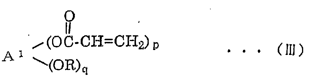
- In the general formula (III), A1 represents a residue group derived from a (p+q)-valent polyhydric alcohol by removing hydroxyl group, and R represents a hydrogen atom or an acyl group excluding acryloyl group. The acyl group is not particularly limited. The preferable examples of the acyl group include saturated and unsaturated aliphatic acyl groups having 2 to 20 carbon atoms. p represents an integer of 2 to 10, q represents an integer of 0 to 8, and p+q represents an integer of 2 to 10.
- Among the compounds represented by the general formula (III), preferred are compounds in which p represents an integer of 3 to 6, q represents an integer of 0 to 3 and p+q represents an integer of 3 to 6, from the standpoint of the effect.
- To form as acrylate represented by the general formula (III), a polyhydric alcohol represented by general formula (IV):
- As the compound represented by the general formula (III), polyvalent esters which are obtained from dipentaerythritol and acrylic acid and have 3 to 6 acryloyl groups in one molecule, and modified dipentaerythritol acrylates which are modified at an acyl group and have 3 to 5 acryloyl groups in one molecule are preferable from the standpoint of the effect.
- The above compounds are available as commercial products as shown in the following.
- For example, compounds expressed by the following formula:(a mixture of a compound expressed by the above formula in which a=5 and b=1, and a compound expressed by the above formula in which a=6 and b=0) are available as KAYARAD DPHA (a trade mark; manufactured by NIPPON KAYAKU Co, Ltd.).

- Also compounds represented by the following general formula:(R7 represents an alkynoyl group) are commercially available as KAYARAD D-310 (a trade mark; manufactured by NIPPON KAYAKU Co., Ltd.) in which c=5 and d=1 and as KAYARAD D-330 (a trade mark; manufactured by NIPPON KAYAKU Co., Ltd.) in which c=3 and d=3 is available.
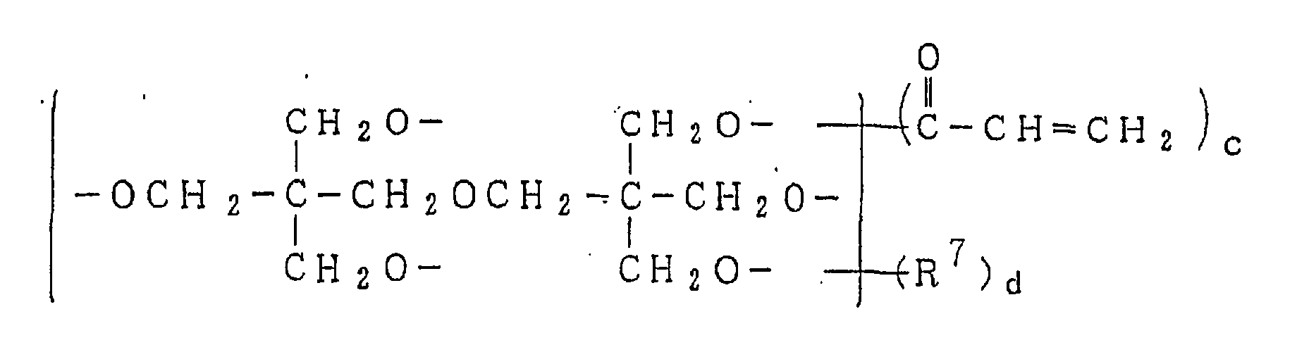
- The acrylate of component (B) exhibits an effect of improving heat resistance of the rubber composition. It is considered that the effect is exhibited because of effective formation of C-C crosslink by the reaction with the conjugated C=C bond in the main chain which is formed at the time of the scission of a crosslink at a high temperature.
- The amount of (B) component is set in the range of 0.5 to 20 parts by weight per 100 parts by weight of the rubber component (A). When the amount is less than 0.5 parts by weight, there is the possibility that the effect of preventing heat aging is not sufficiently exhibited and the desired effect of improving the heat resistance is not exhibited. When the amount exceeds 20 parts by weight, the effect is not exhibited to the degree expected from the amount, and economic disadvantage arises. Moreover, it causes a deterioration in other physical properties of the obtained rubber composition. From the standpoint of the effect of preventing heat aging, other properties of the rubber composition and economy, it is more preferable that the amount of (B) component is in the range of 0.7 to 15 parts by weight and the most preferably in the range of 1.0 to 10 parts by weight.
- In the present invention, where desired, other agents for preventing heat aging can be suitably used in combination with the compounds of (B) component. Examples of the other agent include
sodium 1,6-hexamethylenedithiosulfate dihydrate and compounds having two or more ester groups in one molecule. - The compound having two or more ester groups in one molecule is not particularly limited. Acrylates and methacrylates are preferable and polyvalent esters obtained from polyhydric alcohols and acrylic acid or methacrylic acid are more preferable.
- Examples of the polyhydric alcohol include alkylene glycols such as ethylene glycol, propylene glycol, butylene glycol, pentanediol and hexanediol; polymers of the alkylene glycols; compounds obtained by substituting methylol group into these compounds; pentaerythritol; addition products of alkylene oxides to polyhydric alcohols; and polyesters and oligoesters having two or more alcoholic hydroxyl groups. Among these compounds, compounds obtained by substituting methylol group into alkylene glycols and polymers of these compounds are preferable.
- Examples of the compound having two or more ester groups in one molecule include 1,3-butylene glycol diacrylate, 1,5-pentanediol diacrylate, neopentyl glycol diacrylate, 1,6-hexanediol diacrylate, diethylene glycol diacrylate, triethylene glycol diacrylate, tetraethylene glycol diacrylate, polyethylene glycol diacrylate, polypropylene glycol diacrylate, pentaerythritol triacrylate, trimethylolpropane triacrylate, pentaerythritol tetraacrylate, dipentaerythritol hexaacrylate, dipentaerythritol pentaacrylate, oligoester polyacrylate, dipropylene glycol dimethacrylate, trimethylolethane trimethacrylate, trimethylolpropane trimethacrylate, dipentaerythritol pentamethacrylate and dipentaerythritol trimethacrylate. Among these compounds, dipentaerythritol pentamethacrylate, dipentaerythritol trimethacrylate and trimethylol-propane trimethacrylate are preferable.
-
Sodium 1,6-hexamethylenedithiosulfate dihydrate described above exhibits the effect of suppressing scission of intermolecular crosslink between polymer molecules constituting the rubber component. The function of the compound having two or more ester groups in one molecule can be considered as follows. When the temperature of the rubber composition is elevated to 170°C or higher, degradation of rubber starts and scission of crosslink points and polymer chains begins to take place. On the other hand, C-C crosslink with the aid of the above compound takes place at a same time. Therefore, the decrease in the modulus is suppressed and, as the result, heat generation is suppressed even at high temperatures. - In the rubber composition used in the present invention, a reinforcing filler (component C) may be further used. The reinforcing filler is not particularly limited and can be suitably selected from those conventionally used in the rubber industry. It is preferable that carbon black, silica or a reinforcing inorganic filler represented by the general formula shown below is used.
- Carbon black is not particularly limited and can be suitably selected from those conventionally used in the rubber industry. It is preferable that carbon black has a nitrogen adsorption specific surface area measured by the BET method of in the range of 50 to 400 m2/g. Specifically, HAF, GPF and FEF are preferable from the standpoint of the balance between the reinforcing property and the resistance to heat generation.
- It is preferable that the reinforcing inorganic filler used in the present invention as component (C) is porous. It is more preferable that the reinforcing inorganic filler has a nitrogen adsorption specific surface area measured by the BET method of in the range of 50 to 400 m2/g.
- Silica is not particularly limited and can be suitably selected from those conventionally used in the rubber industry. Examples of the silica include wet silica and dry silica. Preferable examples of silica include NIPSIL AQ manufactured by NIPPON SILICA INDUSTRIAL Co., Ltd.
- As the other reinforcing inorganic fillers, compounds represented by the following general formula:
- Among these reinforcing inorganic fillers, aluminum hydroxide, aluminum oxide, clay and zeolite are more preferable and aluminum hydroxide is the most preferable.
- The above reinforcing inorganic filler and carbon black may be used in combination.
- In the rubber composition used in the present invention, in addition to the components described above, various additives conventionally used in the rubber industry may suitably be used. Examples of the additives include a vulcanizing agent such as sulfur and peroxides, a vulcanization accelerator, an antioxidant, a softener and an inorganic filler. The rubber composition used in the present invention may be used as a composite with particles, fibers and cloths of various materials.
- The pneumatic tire of the present invention can be produced by a conventional process with application of the rubber composition exhibiting excellent heat resistance and excellent durability described above to bead fillers and/or reinforcing layers of side wall portions.
- It is preferable that the rubber member disposed in the side wall portions is disposed at an inner side of the tire and adjacent to the carcass layer.
- The carcass ply used in the present invention comprises, for example, an aliphatic polyamide and a rubber composition, and can be produced by a conventional process. A green tire is produced by applying this carcass ply and the obtained green tire is vulcanized.
- The structure of the carcass of the pneumatic tire of the present invention is not particularly limited. Examples of the carcass structure include IP structure with one ply, 2P structure with two plies and 3P structure with three plies. Each ply may be a turn-up ply which is turned up around a bead portion or a down ply which extends downwards to a bead portion or one having a so-called envelope structure in which the end of a turn-up ply extends to below a belt. At least one layer of the ply is the turn-up ply.
- The rubber-filament fiber composite is disposed in the side wall portion of a tire. The composite is disposed at least at one part of the side wall portion. The composite may be disposed in the entire part of the side wall portion extending from the lower end of the bead portion to below the belt. The composite may be disposed at the inside or at the outside of the carcass ply or between a plurality of carcass plies.
- An example of a tire of the present invention will be described with reference to a figure in the following. In Figure 1, a
carcass 4 has a 2P structure comprising a turn-up ply 4a and adown ply 4b which are disposed substantially parallel to each other in the radial direction of thetire 1. The turn-up ply 4a is reinforced with a cord made of Nylon 66, and thedown ply 4b is disposed at the outside of the turn-up ply 4a. Each of end portions of the turn-up ply 4a are turned around a pair of bead portions comprising a pair of right and leftbead cores 6 and a corresponding pair ofbead fillers 7. In the crown portion, at the outside in the radial direction of the tire of thecarcass 4, abelt 5 comprising two plies each reinforced with a steel cord is disposed. At the outside, in the radial direction of the tire, of thebelt 5, atread rubber 3 is disposed. On the carcass layer at both sides of thetread rubber 3,side wall rubbers 2 are disposed. In each side wall portion, a reinforcingrubber layer 8 which partially supports the load and has a sectional shape of a crescent is disposed at the inside of the turn-up ply 4a. At the inside of each reinforcingrubber layer 8, a rubber-filament fiber composite 9 is disposed. The reinforcing rubber layer comprises a rubber composition which is formed by the formulation shown in Table 18 and has a hardness after vulcanization of 80°. The reinforcing rubber layer has the maximum thickness of 11 mm. The rubber composition used for the rubber-filament fiber composite is the same as that used for the reinforcing rubber layer. - The rubber used for the reinforcing
rubber layer 8 which reinforces theside wall portion 2 may be a composite comprising organic fibers or inorganic particles. The sectional shape of the reinforcingrubber layer 8 is not particularly limited as long as the function of reinforcing the side wall portion can be exhibited. - In the pneumatic tire of the present invention, at least one of the
bead filler 7 and the reinforcingrubber layer 8 is formed with the above rubber composition having excellent heat resistance and excellent durability. - As the gas filling the inside of the pneumatic tire of the present invention, the air or an inert gas such as nitrogen gas can be used.
- When the pneumatic tire of the present invention is used for driving under the normal condition, deterioration in the ride comfort and the noise level due to the increase in the modulus are substantially absent. Further when the temperature of the rubber composition is elevated to 170°C or higher by a large deformation caused by for example puncture of the tire, the decrease in the modulus is suppressed and heat generation at the high temperature is suppressed.
- Therefore, the pneumatic tire of the present invention in which the rubber composition is used for the bead filler or the reinforcing rubber layer in the side wall portion exhibits remarkable improvement in the durability, in particular, under the run flat state and the driving distance under the run flat state can be remarkably increased.
- The rubber-filament fiber composite can be disposed in the
side wall portion 2. The position of disposing the composite is not particularly limited and can be suitably selected depending on the application. For example, the position may be between the carcass ply and an inner liner layer, between the carcass plies, between the carcass ply and the side reinforcing layer or between the side reinforcing layer and the side wall rubber. - The size of a rubber-non-woven fabric composite is not particularly limited. It is preferable that the rubber-non-woven fabric composite has a dimension of about 15 mm extending in the longitudinal direction at both sides of the thickest position of the side reinforcing layer. The rubber-non woven fabric composite may have a dimension extending to the entire side wall portion.
- The material of the non-woven fabric is not particularly limited and can be selected by the application. A filament of an organic fiber is preferable, and more preferably a filament of an organic fiber having a melting point or a softening point of 250°C or higher and the most preferably an aramide filament.
- In the present invention, it is preferable that a rubber-filament fiber composite constituted with a filament fiber and a rubber composition is applied. The material of the filament fiber constituting the rubber-filament fiber composite is not particularly limited. As the material of the filament fiber, one fiber or a mixture of a plurality of fibers selected from fibers of natural macromolecules such as cotton fibers, rayon fibers and cellulose fibers; fibers of synthetic macromolecules such as aromatic polyamide fibers; aliphatic polyamide fibers; polyester fibers, polyvinyl alcohol fibers, and polyimide fibers; carbon fibers; glass fibers; and steel wires, may be used. From the standpoint of the dimensional stability at high temperatures, aromatic polyamide fibers, rayon fibers,
polyethylene 2,6-naphthalate fibers, polyimide fibers, carbon fibers, glass fibers and steel wires are preferable. Examples of the aromatic polyamide fiber include fibers of poly-para-phenylene terephthalamide, poly-meta-phenylene terephthalamide, poly-para-phenylene isophthalamide and poly-meta-phenylene isophthalamide. - As the aromatic polyamide fiber, para-aramide fibers are preferable. Examples of the para-aramide fiber include fibers of copoly-
para-phenylene 3,4-oxydiphenylene terephthalamide. poly-para-phenylene terephthalamide, poly-meta-phenylene terephthalamide, poly-para-phenylene isophthalamide and poly-meta-phenylene terephthalamide. Among these fibers, fibers of para-aramide fibers are preferable. As the commercial product, TECHNOLA (a trade mark; manufactured by TEIJIN Limited) and KEVLAR (a trade mark; manufactured by E.I. DU PONT de Nemours and Company) are available. - As for the non-woven fabric used in the present invention, it is preferable that the diameter or the maximum diameter of the filament of the non-woven fabric is in the range of 0.1 to 100 □ m and more preferably in the range of 10 to 35 □ m so that rubber sufficiently penetrates through gaps between the filament fibers. When the diameter of the filament of the non-woven fabric is smaller, the gap between the filaments is not sufficient to make the penetration of rubber into the inside of the non-woven fabric difficult. So, a resultant rubber-filament fiber composite occasionally fail to exhibit its function sufficiently. On the other hand, when the diameter of the filament of the non-woven fabric is larger, the bending modulus of the filament fiber itself increases and formation of entanglements between the fibers sufficient for forming the non-woven fabric tends to become difficult. Therefore, a resultant rubber-filament fiber composite occasionally fail to exhibit its function sufficiently.
- It is preferable that the length of the fiber applied in the rubber-filament fiber composite is 8 mm or longer and more preferably 10 mm or longer. When the length of the fiber is shorter, entanglements between the filament fibers is insufficient and the strength as the reinforcing layer tends to be difficultly maintained.
- The organic or inorganic fiber used in the present invention may have a multi-layer structure in which a plurality of components are laminated together or a structure having cavities at the inside of the fiber such as a hollow structure and a porous structure. The fiber may have various sectional shapes such as a circular shape, a elliptic shape, a rugged shape or a shape of a petal. It is preferable that the fiber has a sectional shape having less roughness on the surface such as the circular shape and the elliptic shape. The shape having less roughness on the surface means a shape which hardly project shadows on the surface due to the roughness of the surface when the fiber is subjected to irradiation with an electric field or particles from the outside.
- The filament fiber constituting the rubber-filament fiber composite used in the present invention can be used in the form of aggregates of fibers which are substantially not bundled together, for example, in the form of aggregates of fibers which are entangled together. In the aggregates, fibers are, unlike a tire fabric, not twisted together or woven to a fabric. Examples of the form of the aggregate of fibers include glass wool, non-woven fabrics, knit fabrics, nets and the like.
- In the rubber-filament fiber composite used in the pneumatic tire of the present invention, it is preferable that a non-woven fabric is used as the filament fiber. As a process for preparing a non-woven fabric, needle punch process, carding process, melt blow process and spun bond process can be used. As the non-woven fabric, non-woven fabrics prepared by the carding process in which filaments are entangled together by using water stream or needles and the spun bond process in which filaments are bonded to each other are preferable.
- It is preferable that the unit weight (the weight per 1 m2) of the non-woven fabric is in the range of 10 g to 300 g. When the unit weight exceeds 300 g/m2, rubber does not penetrate into the gaps at the inside of the non-woven fabric although the condition may be different depending on the fluidity of the rubber. When the non-woven fabric as a member of the tire is considered, this condition is not preferable from the standpoint of peeling resistance of the rubber-non-woven fabric composite. When the unit weight is smaller than 10 g/m2, it becomes difficult that the uniformity of the non-woven fabric itself is maintained and uneven non-woven fabric is formed. This causes increases in the fluctuations in strength, rigidity and elongation at break of the rubber-non-woven fabric composite and physical properties of the tire obtained after vulcanization cannot be kept constant. Therefore, such unit weights are not preferable.
- It is preferable that the thickness of the non-woven fabric as measured under the pressure of 20 g/cm2 is in the range of 0.05 to 2.0 mm and more preferably in the range of 0.1 to 0.5 mm. When the thickness is smaller than 0.05 mm, it is difficult that the uniformity of the non-woven fabric is maintained and strength and rigidity of the composite with rubber are insufficient. When the thickness exceeds 2.0 mm, the gauge of the composite with rubber increases and the thickness is not preferable for a member of a tire.
- The rubber and the filament fiber are formed into a composite by applying an unvulcanized rubber composition to a filament fiber in advance while the materials are processed in the unvulcanized stage. Specifically, the materials may be mixed together by using a mixing machine conventionally used in the rubber industry such as rolls and a Banbury mixer. From the standpoint of dispersion, it is preferable that the filament is added into the rubber in small separate portions. When a non-woven fabric is used as the filament fiber, an unvulcanized rubber composition in the sheet form is pressed against the non-woven fabric on both upper and lower faces or on one face by using a press or a heated roll and the air inside the non-woven fabric is sufficiently replaced with the unvulcanized rubber composition. Depending on the fluidity of the unvulcanized rubber composition, it may be required to conduct the pressing at an elevated temperature at which the vulcanization does not substantially takes place. As another method, the unvulcanized rubber composition is made into a liquid form with a solvent and tackiness is provided by coating the non-woven fabric with the fluid composition.
- It is preferable that the content of the filament fiber in the rubber-filament fiber composite is in the range of 4 to 50% by weight. When the content of the filament fiber is smaller than 4% by weight, uniformity cannot be maintained and rigidity as the reinforcing layer cannot be exhibited. When the content of the filament fiber exceeds 50% by weight, portions in which fibers are continuous increase in the rubber-filament fiber composite. This causes a decrease in durability of the rubber-filament fiber composite and the durability of the tire tends to decrease. Therefore, contents of the filament fiber outside the above range are not preferable.
- When adhesion between the filament fiber and the rubber is sufficient in the preparation of the composite, no pretreatment for adhering the filament fiber is required. When the adhesion is not sufficient, the filament fiber may be treated by a dipping heat set treatment or a surface treatment described in the following in the same manner as that used for enhancing adhesion of fibers for tire cords with rubber.
- In the present invention, a coating film is formed on the filament forming the above non-woven fabric with a metal or a metal compound which is reactive with sulfur by the physical vapor deposition (PVD) process or the chemical vapor deposition (CVD) process. The formation of the coating film by the PVD process or the CVD process has advantages to be low level of environmental contamination since no solvents are used and that, unlike the conventional dipping treatment and the plating treatment, gaps between fibers in the non-woven fabric are not choked since the coating film is formed via the gas phase.
- Examples of the PVD process which can be applied to the present invention include vacuum vapor deposition processes such as the vapor deposition process using resistance heater and vapor deposition process using electron beams; the epitaxy process using molecular beams; the laser abrasion process; sputtering processes such as direct current sputtering process, high frequency sputtering process, magnetron sputtering process and ECR sputtering process; ion beam process; ion plating process such as high frequency ion plating process; ionized cluster beam film forming process; and the ion beam process. Examples of the CVD process include the heat CVD processes such as the ordinary pressure CVD process and the reduced pressure CVD process; the organometallic CVD process; the photo CVD process; and the plasma CVD processes such as the direct current plasma CVD process, the high frequency plasma CVD process, the microwave plasma CVD process and the ECR plasma CVD process. Among these processes, the sputtering processes are preferable and the magnetron sputtering process is more preferable.
- The reasons why the sputtering processes are preferable are that the film formation can be conducted while the temperature at the surface of the non-woven fabric is kept low, that the effect of out gases from the non-woven fabric is small since the operating pressure during the film formation is relatively high such as 5 × 10⁻² to 1×101 Pa, and that particles sputtered from a target are likely to be scattered with the atmospheric gas such as argon (Ar) before the particles reach the surface of the non-woven fabric and "turning around" tends to take place. Due to the turning around, films can be sufficiently formed on portions not faced to the target and on portions at the back side of the non-woven fabric even though the non-woven fabric has a complicated shape.
- The conditions of the sputtering and, in particular, the magnetron sputtering, are as follows. As the atmospheric gas, an inert gas such as Ar, He, Ne and Kr, and preferably Ar, is used and, where necessary, a reactive gas may be mixed with the inert gas. Examples of the reactive gas include O2 and H2O in the oxidizing system, N2 and NH3 in the nitriding system and CH4 in the carbonizing system. The ratio of the amounts of the inert gas to the reactive gas (the ratio of the volumes in the supplied gas) is 100/0 to 0/100 and preferably 100/0 to 20/80.
- Where necessary, a bias voltage may be applied to the non-woven fabric of the substrate. In this case, any of the direct current bias voltage and the alternating current bias voltage may be applied. When the alternating current bias voltage is applied, it is preferable that a pulse voltage or a high frequency (rf) voltage is applied. When the direct current bias voltage is applied, it is preferable that the voltage is in the range of -1 to +1 kV.
- The pressure of the gas is not particularly limited as long as the sputtering can be conducted. It is preferable that the pressure of the gas is in the range of 1 × 10⁻² to 5×10² Pa and more preferably 5×10⁻² to 1×101 Pa. As the frequency of the power source (supplied to the target), any of the conventional direct current and alternating current may be used. In general, a direct current power source or a high frequency (rf) power source is used. A pulse power source may also be used. The so-called ionizing magnetron sputtering in which particles in the sputter are activated by generating inductive plasma between the target and the substrate may also be used.
- It is preferable that the average thickness of the coating film formed by the deposition in the gas phase is in the range of 5×10⁻¹⁰ to 1×10⁻⁵ m and more preferably in the range of 1×10⁻⁹ to 5×10⁻⁷ m. When the thickness is too smaller, adhesion is insufficient. When the thickness is too larger, the coating film tends to be separated from the substrate because of the internal stress in the coating film. It is sufficient that the above coating film is formed on the surface of the fiber in an amount necessary for the reaction of sulfurization. It is not always necessary that the coating film is formed uniformly. It occasionally occurs that the reaction with oxygen and water vapor takes place because of exposure to the atmospheric air during or after the film formation and the coating film is contaminated with impurities such as oxygen and hydrogen. Where necessary, a plasma treatment, ion inplantation, ion irradiation and heat treatment may be conducted after the coating film has been formed so that the surface condition, the reactivity and the internal stress of the coating film are improved. It is desirable that the surface of the non-woven fabric is cleaned before the coating film is formed, where necessary. For the cleaning, cleaning with a solvent or the combination of cleaning with a solvent and discharge treatment can be used. The effect of the cleaning may be improved by using combinations of other methods.
- As the metal or the metal compound reactive with sulfur which can be used in the present invention, alloys, oxides and nitrides can also be used. Any materials can be used as long as the sulfurization reaction takes place between the materials and sulfur in the rubber during the vulcanization. Examples of such materials include metals such as Co, Cu, Zn, Cr, Al, Ag, Ni, Pb, Ti and W; alloys of two or more of these metals; and compounds of these metals such as oxides, nitrides, carbides, sulfides and sulfates of these metals. Among these materials, metals and alloys such as Co, alloys of Co and Cr, alloys of Cu and Zn and alloys of Cu and Al and oxides of these metals and alloys are preferable and Co and oxides of Co are more preferable (Japanese Patent Application Laid-Open Nos. Showa 62(1987)-87311, Showa 62(1987)-246278 and Heisei 1(1989)-290342). The compounds such as the oxides, the nitrides and the carbides may be obtained from the stoichiometric amounts of the component materials but are not limited to those obtained from the stoichiometric amounts of the component materials. It is preferable that the amount of the metal is larger than the stoichiometric amount.
- When the surface of the non-woven film having the above coating film is coated with the unvulcanized rubber and the unvulcanized rubber is pressed under heating against the surface of the non-woven fabric, it is considered that adhesion takes place due to the sulfurization reaction between the above coating film and the rubber during vulcanization of the rubber. Since the vulcanization reaction and the sulfurization reaction are competitive reactions, a suitable matching of these reactions is necessary so that both reactions take place in a suitable manner. When the coating film is formed by the sputtering process, a thin film of a compound having a suitable reactivity in the sulfurization reaction can be easily formed by using a suitable amount of a reactive gas such as oxygen and nitrogen in combination with the inert gas such as Ar during the film formation.
- The rubber component used for the carcass ply, the rubber-filament fiber composite and the reinforcing rubber layer is not particularly limited. For example, natural rubber (NR), butadiene rubber (BR), styrene-butadiene rubber (SBR) and isoprene rubber (IR) can be used.
- As for the physical properties of the rubber composition used for the composite member, it is preferable that the tensile stress at 50% elongation (M50) is in the range of 2 to 9 MPa and the tensile stress at 100% elongation (M100) is in the range of 1 to 15 MPa and more preferably in the range of 4 to 15 MPa. It is preferable that the same rubber composition as that used for the side reinforcing rubber is used as the rubber composition for the rubber-non-woven fabric composite.
- The present invention will be described more specifically with reference to examples in the following. However, the present invention is not limited to the examples.
- Various measurements were conducted by the following methods.
- The content of vinyl linkages in the portion of conjugated diene units (the 1,2-structure in the butadiene portion) is obtained by the infrared spectroscopy (the Morero's method).
- From a slab sheet having a thickness of 2 mm which is obtained by vulcanizing a rubber composition under a condition of 160°C for 12 minutes, a sheet having a width of 5 mm and a length of 40 mm is cut out and used as a sample. Using the obtained sample, the dynamic storage modulus (E') is measured under a condition of a distance between clamps of 10 mm, an initial strain of 200 micrometers (microns), a dynamic strain of 1%, a frequency of 52 Hz, an initial temperature of 25°C, a rate of elevation of the temperature of 3°C/minute and a final temperature of 250°C.
- The ratio of the minimum value of the dynamic storage modulus in the temperature range of 200 to 250°C to the value of the dynamic storage modulus at 50°C is expressed as an index. The larger the index, the smaller the decrease in the dynamic storage modulus due to elevation of the temperature.
- The tensile stress of a rubber composition used for a filament fiber composite and a reinforcing rubber layer is measured by the method of Japanese Industrial Standard K6301-1995.
- A test tire is attached to a passenger car and the ride comfort is evaluated by a feeling test by two professional drivers. The results of the test are expressed by a criterion of 1 to 10 points and the average value is used as the result of the evaluation. The larger the value, the better the ride comfort.
- A test tire is attached to a rim under the atmospheric pressure and, after the tire is inflated to an internal pressure of 200 kPa, the inflated tire is left in a room at 38°C for 24 hours. Then, the internal pressure is released to the atmospheric pressure by opening the valve core, and the tire is subjected to a drum driving test under a specified load at a speed of 89 km/hour at a room temperature of 38°C. The distance driven before a damage took place is used as the run flat durability. The run flat durability is expressed as an index based on the result of a control, which is set at 100. The larger the index, the better the run flat durability. The specified loads are as follows: 4.58 kN (467 kgf) for a radial tire for passenger cars having a size of 205/60815; 4.32 kN (440 kgf) when the size is 205/55R16; 4.06 kN (414 kgf) when the size is 215/45R17; 4.6 kN (470 kg) for a radial tire for passenger cars having a size of 225/45ZR17; 5.4 kN (550 kg) for a radial tire for passenger cars having a size of 225/55817; and 5.14 kN (524 kg) for a radial tire for passenger cars having a size of 245/45ZR17.
- Rolling resistance is measured by coasting method under a condition of an internal pressure of a tire of 1.7 kg/cm2, a load of 100% based on the value of the Japanese Industrial Standard and an initial speed of inertial driving of 100 km/hour. The result is expressed by an index based on the result of a control, which is set at 100. The smaller the index, the smaller the rolling resistance.
- Abbreviations used in the tables are shown in the following.
- 1) Molecular weight
- Mw: Weight-average molecular weight
- Mw/Mn: Molecular weight distribution
- 2-1) End modifiers for carbon black
- TTC: tin tetrachloride (SnCl4)
- TBTC: tributyltin chloride(Bu3SnCl)
- DOTDC: dioctyltin dichloride (Oct2SnCl2)
- DBTDC: dibutyltin dichloride (Bu2SnCl2)
- DMABP: 4-(dimethylamino)benzophenone
- DMABA: 4-dimethylaminobenzylideneaniline
- DMABB: 4-dimethylaminobenzylidenebutylamine

- DMI: dimethylimidazolidinone

- NMP: N-methylpyrrolidone

- c-MDI: crude MD1, manufactured by NIPPON POLYURETHANE Co., Ltd.;
MR400

- 2-2) End modifiers for both of inorganic fillers and carbon black
- TEOS: tetraethoxysilane
- TEOSDI: 1-{3-(triethoxysilyl)propyl}-4, 5-dihydroimidazole

- S340: N-(1,3-dimethylbutylidene)-3-(triethoxysilyl)-1-propaneamine

- DEAPTE: dimethylaminopropyltriethoxysilane

- GPEOS: 3-glycidoxypropyltriethoxysilane

- 3) Modifying initiator
- LHMI: a reaction product of n-butyllithium (n-BuLi) and hexamethyleneimine (HMI)
- 4) Compounding ingredients
- Component (A)
- BR01: [a trade mark; manufactured by JSR Corporation; cis-1,4-polybutadiene; the content of vinyl linkages: 2.5%.]
- Buna VI 47-0: a trade mark; manufactured by BAYER AKTIENGESELLSCHAFT; a butadiene rubber; the content of vinyl linkages: 47%.
- Buna VI 70-0 HM: a trade mark; manufactured by BAYER AKTIENGESELLSCHAFT; a butadiene rubber; the content of vinyl linkages: 70%.
- Buna VI 80-0 HM: a trade mark; manufactured by BAYER AKTIENGESELLSCHAFT; a butadiene rubber; the content of vinyl linkages: 80%.
- Component (B): heat resistance improver
- Compound A represented by general formula (I): 1,6-bis(N,N'-dibenzylthiocarbamoyldithio)hexane (VULCUREN TRIAL PRODUCT KA9188; manufactured by BAYER AKTIENGESELLSCHAFT).
- Compound B represented by general formula (I): 1,6-bis(N,N'-dimethylthiocarbamoyldithio)hexane (a tentative synthesized product).
- Compound C represented by general formula (I): 1,6-bis(N,N'-diethylthiocarbamoyldithio)hexane (a tentative synthesized product).
- Compound D represented by general formula (I): 1,6-bis(N,N'-di(2-ethylhexyl)thiocarbamoyldithio)hexane (a tentative synthesized product).
- Compound E represented by general formula (I): 1,6-bis(benzothiazolyldithio)hexane (a tentative synthesized product).
- Citraconimide compound A: PERKALINK 900 [a trade mark; manufactured by FLEXSYS K.K.].
- Citraconimide compound B: N,N'-m-phenylene-biscitraconimide (a tentative synthesized product).
- Acrylate A: KAYARAD D-310 [a trade mark; manufactured by NIPPON KAYAKU Co., Ltd.].
- Acrylate B: KAYARAD DPHA [a trade mark; manufactured by NIPPON KAYAKU Co., Ltd.].
- Acrylate C: KAYARAD D-330 [a trade mark; manufactured by NIPPON KAYAKU Co., Ltd.].
- (C) Other compounding ingredients
- 1) Carbon black
- NPG: GPF manufactured by ASAHI CARBON Co., Ltd.; trade mark: #ASAHI NPG.
- #55: FEF manufactured by ASAHI CARBON Co., Ltd.; trade mark: ASAHI #55.
- #60: FEF manufactured by ASAHI CARBON Co., Ltd.; trade mark: ASAHI #60.
- 2) Softener: "DIANA PROCESS OIL NP-24" [a trade mark; manufactured by IDEMITSU KOSAN Co., Ltd.].
- 3) Zinc oxide: No. 3 [a trade mark; manufactured by MITSUI MINING & SMELTING Co., Ltd.]
- 4) Stearic acid: "LUNAC RC BEADS" [a trade mark; manufactured by KAO Corporation].
- 5) Antioxidant: NOCRAC 6C; a trade mark; manufactured by OUCHISHINKO CHEMICAL INDUSTRIAL Co., Ltd.; N-phenyl-N'-(1,3-dimethylbutyl)-p-phenylenediamine.
- 6) Vulcanization accelerator: NOCCELOR NS; a trade mark; manufactured by OUCHISHINKO CHEMICAL INDUSTRIAL Co., Ltd.; N-tert-butyl-2-benzothiazolyl sulfenamide.
- 7) Sulfur: MUCRON-OT; a trade mark; manufactured by SHIKOKU Corporation.
- 8) Silica: NIPSIL AQ; a trade mark; manufactured by NIPPON SILICA INDUSTRIAL Co., Ltd..
- 9) Silane coupling agent: Si69; a trade mark; manufactured by DEGUSSA AG. Processes [I] to [III] for producing polymers used as the rubber component will be described in the following.
-
- Into a 8 liter pressure-resistant reactor having a jacket for adjusting the temperature, the reactor which had been dried and purged with nitrogen, 3 kg of cyclohexane, 500 g of butadiene monomer and 0.225 mmole of ditetrahydrofurylpropane (DTHFP) were placed. After 4.5 mmole of n-butyllithium (BuLi) is added to the resultant mixture, the polymerization is allowed to proceed at an initial temperature of 40°C for 1 hour. The polymerization is allowed to proceed while the temperature is elevated and the temperature in the jacket is adjusted so that the final temperature of the reaction system did not exceed 75°C. The polymerization system is completely homogeneous and transparent without precipitates from the start to the end of the polymerization. The conversion of the polymerization is about 100%.
- To the obtained polymerization system, 0.11 ml of SnCl4 (TTC; a 1 M cyclohexane solution) is added as the end modifier and the modification reaction is allowed to proceed for 30 minutes. To the resultant polymerization system, 0.5 ml of a 5% isopropanol solution of 2,6-di-t-butyl-p-cresol (BHT) is added to terminate the polymerization. The obtained polymer is dried by a conventional process and polymer A is obtained.
- Polymers B and I to X were obtained by the same procedures as those conducted for producing polymer A except that BuLi and DTHFP were used in amounts shown in Table 1 and end modifiers shown in Table 1 were used in amounts also shown in Table 1.
- Polymer Y is obtained in the same manner as in Preparation Example 1 except that TTC as the end modifier is not used.
- The microstructures (the content of vinyl linkages), the molecular weights (Mw) and the molecular weight distributions (Mw/Mn) of polymers A, B, I to Y were measured. The results are shown in Table 1.
- Into a 8 liter pressure-resistant reactor having a jacket for adjusting the temperature, the reactor which had been dried and purged with nitrogen, 3 kg of cyclohexane, 500 g of butadiene monomer and 1.6 mmole of ditetrahydrofurylpropane (DTHFP) were placed. After 4 mmole of n-butyllithium (BuLi) is added to the resultant mixture, 0.8 mmole of hexamethyleneimine (HMI) is quickly added and the polymerization is allowed to proceed at an initial temperature of 40°C for 1 hour. The polymerization is allowed to proceed while the temperature is elevated and the temperature in the jacket is adjusted so that the final temperature of the reaction system did not exceed 75°C. The polymerization system is completely homogeneous and transparent without precipitates from the start to the end of the polymerization. The conversion of the polymerization is about 100%.
- To the obtained polymerization system, 0.81 ml of SnCl4 (TTC; a 1 M cyclohexane solution) is added as the end modifier and the modification reaction is allowed to proceed for 30 minutes. To the resultant polymerization system, 0.5 ml of a 5% isopropanol solution of BHT is added to terminate the polymerization. The obtained polymer is dried by a conventional process and polymer Z is obtained.
- Polymer Y is obtained by the same procedures as those conducted for producing polymer AA except that BuLi is used in an amount shown in Table 1 and an end modifier shown in Table 1 is used.
- The microstructures (the content of vinyl linkages), the molecular weights (Mw) and the molecular weight distributions (Mw/Mn) of the obtained modified butadiene polymers Z and AA were measured. The results are shown in Table 1.
Preparation Example 1 2 3 4 5 6 7 BR-based polymer (batch polymerization) A B I J K L M Amount of n-BuLi (mmole) 4.5 3 4 4 4 4 5 Amount of DTHFP (mmole) 0.225 0.18 1.6 1.6 1.6 1.6 1.6 Chain end modifier TTC TTC TTC TBTC DOTDC DBTDC TEOSDI amount (mmole) 0.11 0.11 0.8 3.2 1.6 1.6 3.2 Modifying initiator - - - - - - - Molecular weight Mw(× 10,000) 20.0 40.0 65.0 23.0 38.0 37.0 29.0 Mw/Mn 1.1 1.2 1.8 1.1 1.3 1.3 1.3 Microstructure content of vinyl linkages (%) 25 25 50 50 51 49 48 Preparation Example 8 9 10 11 12 13 14 BR-based polymer (batch polymerization) N O P Q R S T Amount of n-BuLi (mmole) 4 4 4 4 4 5.5 5.5 Amount of DTHFP (mmole) 1.6 1.6 1.6 1.6 1.6 1.6 1.6 Chain end modifier DMABP DMABA DMABB DMI NMP S340 c-MDI amount (mmole) 3.2 3.2 3.2 3.2 3.2 4.1 3 Modifying initiator - - - - - - - Molecular weight Mw (× 10,000) 23.0 23.0 23.0 25.0 25.0 28.0 36.0 Mw/Mn 1.1 1.1 1.1 1.1 1.1 1.3 1.4 Microstructure content of vinyl linkages (%) 48 52 52 51 49 52 51 Preparation Example 15 16 17 18 19 20 21 BR-based polymer (batch polymerization) U V W X Y Z AA Amount of n-BuLi (mmole) 4 4 4 4 4 4 5.5 Amount of DTHFP (mmole) 1.6 1.6 0.8 0.4 1.6 1.6 1.6 Chain end modifier TTC/DMI TTC/TBTC TTC TTC TTC TTC c-MDI amount (mmole) 0.4/1.6 0.4/1.6 0.8 0.8 0.11 0.8 0.8 Modifying initiator - - - - LHMI LHMI LHMI Molecular weight Mw(× 10,000) 42.0 38.0 63.0 64.0 23.5 60.0 38.0 Mw/Mn 1.3 1.2 1.7 1.8 1.1 1.9 1.3 Microstructure content of vinyl linkages (%) 50 48 41 30 52 51 52 - Into a 8 liter pressure-resistant reactor having a jacket for adjusting the temperature, the reactor which had been dried and purged with nitrogen, a 15% by mole of dried cyclohexane solution of butadiene is continuously introduced at a rate of 200 g per minute. Through the same port, a cyclohexane solution (1 mole/liter) of ditetrahydrofurylpropane (DTHFP) and an n-hexane solution (4.5 mmole/liter) of n-butyllithium (BuLi) were continuously introduced at rates of 0.03 mmole/minute and 0.3 mmole/minute, respectively. The polymerization system is always kept at 80°C. The formed polymer is continuously taken out from an upper portion of the reactor and placed into a 1% isopropanol solution of BHT so that a polymer is obtained. The polymerization system is completely homogeneous and transparent without precipitates from the start to the end of the polymerization. The conversion of the polymerization is about 100%. The solid substance of the obtained polymer is dried and rubbery polymer C is obtained.
- Polymers D to H were obtained by the same procedures as those conducted for producing polymer C except that BuLi and DTHFP were introduced at rates (mmole/minute) shown in Table 2.
- The microstructures (the content of vinyl linkages), the molecular weights (Mw) and the molecular weight distributions (Mw/Mn) of butadiene polymers C to H obtained above were measured. The results are shown in Table 2.
Preparation Example 22 23 24 25 26 27 BR-based polymer (continuous polymerization) C D E F G H Amount of n-BuLi (mmole/min) 0.3 0.15 0.2 0.2 0.2 0.2 Amount of DTHFP (mmole/min) 0.03 0.02 0.03 0.04 0.06 0.15 Molecular weight Mw (× 10,000) 35.0 78.0 50.0 50.0 50.0 50.0 Mw/Mn 3.8 3.7 2.1 1.9 2.1 2.1 Microstructure content of vinyl linkages (%) 25 25 30 35 40 50 - Into a 8 liter pressure-resistant reactor having a jacket for adjusting the temperature, the reactor which had been dried and purged with nitrogen, 3 kg of cyclohexane, 475 g of butadiene monomer, 25 g of styrene and 2.5 mmole of ditetrahydrofurylpropane (DTHFP) were placed. After 5.5 mmole of n-butyllithium (BuLi) is added to the resultant mixture, the polymerization is allowed to proceed at an initial temperature of 40°C for 1 hour. The polymerization is allowed to proceed while the temperature is elevated and the temperature in the jacket is adjusted so that the final temperature of the reaction system did not exceed 75°C. The polymerization system is completely homogeneous and transparent without precipitates from the start to the end of the polymerization. The conversion of the polymerization is about 100%.
- To the obtained polymerization system, 5 ml of c-MDI (a 1 M cyclohexane solution) is added and the modification reaction is allowed to proceed for 30 minutes. To the resultant polymerization system, 0.5 ml of a 5% isopropanol solution of 2,6-di-t-butyl-p-cresol (BHT) is added to terminate the polymerization. The obtained polymer is dried by a conventional process and polymer BA is obtained.
- Polymer BB is obtained by the same procedures as those conducted for producing polymer BA except that butadiene and styrene were used in amounts shown in Table 3.
- Polymers BC and BD were obtained by the same procedures as those conducted for producing polymers BA and BB except that n-BuLi is used in amounts shown in Table 3 and c-MDI as the end modifier is not used.
- The microstructures (the content of vinyl linkages), the molecular weights (Mw) and the molecular weight distributions (Mw/Mn) of polymers BA to BD which were styrene-butadiene copolymers modified at the ends or not modified at the ends were measured. The results are shown in Table 3.
- Into a 8 liter pressure-resistant reactor having a jacket for adjusting the temperature, the reactor which had been dried and purged with nitrogen, 3 kg of cyclohexane, 475 g of butadiene monomer, 25 g of styrene, 0.2 mmole of ditetrahydrofurylpropane (DTHFP) and 0.2 mmole of potassium tert-amylate as a cyclohexane solution were placed. After 4.5 mmole of n-butyllithium (n-BuLi) is added to the resultant mixture, the polymerization is allowed to proceed at an initial temperature of 40°C for 1 hour. The polymerization is allowed to proceed while the temperature is elevated and the temperature in the jacket is adjusted so that the final temperature of the reaction system did not exceed 75°C. The polymerization system is completely homogeneous and transparent without precipitates from the start to the end of the polymerization. The conversion of the polymerization is about 100%.
- To the obtained polymerization system, isopropanol is added to terminate the polymerization. The obtained polymer is dried by a conventional process and polymer BE is obtained.
- Polymer BF is obtained by the same procedures as those conducted for producing polymer BE except that butadiene and styrene were used in amounts shown in Table 3.
- The microstructures (the content of vinyl linkages), the molecular weights (Mw) and the molecular weight distributions (Mw/Mn) of polymers BE and BF obtained above were measured. The results are shown in Table 3.
Preparation Example 28 29 30 31 32 33 SBR-based polymer (batch polymerization) BA BB BC BD BE BF Amount of styrene (g) 25 100 25 100 25 100 Amount of butadiene (g) 475 400 475 400 475 400 Amount of n-BuLi (mmole) 5.5 5.5 4.5 4.5 4.5 4.5 Amount of DTHFP (mmole) 2.5 2.5 2.5 2.5 0.2 0.2 Chain end modifier c-MDI c-MDI - - - - amount (mmole) 5 5 - - - - Molecular weight Mw (× 10,000) 37.0 37.0 24.0 34.0 23.0 23.0 Mw/Mn 1.3 1.3 1.0 1.0 1.1 1.1 Microstructure content of vinyl linkages (%) 54 54 55 53 18 18 - Into a 8 liter pressure-resistant reactor having a jacket for adjusting the temperature, the reactor which had been dried and purged with nitrogen, 3 kg of cyclohexane, 500 g of butadiene monomer and 0.05 mmole of ditetrahydrofurylpropane (DTHFP) were placed. After 4 mmole of n-butyllithium (BuLi) is added to the resultant mixture, the polymerization is allowed to proceed at an initial temperature of 40°C for 1 hour. The polymerization is allowed to proceed while the temperature is elevated and the temperature in the jacket is adjusted so that the final temperature of the reaction system did not exceed 75°C. The polymerization system is completely homogeneous and transparent without precipitates from the start to the end of the polymerization. The conversion of the polymerization is about 100%.
- To the obtained polymerization system, 0.5 ml of a 5% isopropanol solution of 2,6-di-t-butyl-p-cresol (BHT) is added to terminate the polymerization. The obtained polymer is dried by a conventional process and polymer AB is obtained.
- Polymers AC and AD were obtained by the same procedures as those conducted for producing polymer AB except that DTHFP is used in amounts shown in Table 1.
- The microstructures (the content of vinyl linkages), the molecular weights (Mw) and the molecular weight distributions (Mw/Mn) of polymers A to C obtained above were measured. The results are shown in Table 4.
- Into a 8 liter pressure-resistant reactor having a jacket for adjusting the temperature, the reactor which had been dried and purged with nitrogen, 3 kg of cyclohexane, 500 g of butadiene monomer and 1.6 mmole of ditetrahydrofurylpropane (DTHFP) were placed. After 5 mmole of n-butyllithium (BuLi) is added to the resultant mixture, the polymerization is allowed to proceed at an initial temperature of 40°C for 1 hour. The polymerization is allowed to proceed while the temperature is elevated and the temperature in the jacket is adjusted so that the final temperature of the reaction system did not exceed 75°C. The polymerization system is completely homogeneous and transparent without precipitates from the start to the end of the polymerization. The conversion of the polymerization is about 100%.
- To the obtained polymerization system, 4.3 ml of tetraethoxysilane (TEOS; a 1 M cyclohexane solution) is added as the modifier and a modification reaction is allowed to proceed for 30 minutes. To the resultant polymerization system, 0.5 ml of a 5% isopropanol solution of 2,6-di-t-butyl-p-cresol (BHT) is added to terminate the polymerization. The obtained polymer is dried by a conventional process and polymer AE is obtained.
- Polymers AF to AI were obtained by the same procedures as those conducted for producing polymer AE except that n-BuLi is used in amounts shown in Table 1 and modifiers shown in Table 1 were used in amounts also shown in Table 1.
- The microstructures (the content of vinyl linkages), the molecular weights (Mw) and the molecular weight distributions (Mw/Mn) of polymers AE to AI obtained above were measured. The results are shown in Table 4.
- Into a 8 liter pressure-resistant reactor having a jacket for adjusting the temperature, the reactor which had been dried and purged with nitrogen, 3 kg of cyclohexane, 500 g of butadiene monomer and 1.6 mmole of ditetrahydrofurylpropane (DTHFP) were placed. After 5 mmole of n-butyllithium (BuLi) is added to the resultant mixture, 4.5 mmole of hexamethyleneimine (HMI) is quickly added and the polymerization is allowed to proceed at an initial temperature of 40°C for 1 hour. The polymerization is allowed to proceed while the temperature is elevated and the temperature in the jacket is adjusted so that the final temperature of the reaction system did not exceed 75°C. The polymerization system is completely homogeneous and transparent without precipitates from the start to the end of the polymerization. The conversion of the polymerization is about 100%.
- To the obtained polymerization system, 4.5 mmole of 1-{3-(triethoxysilyl)propyl}-4,5-dihydroimidazole (TEOSDI; a 1 M cyclohexane solution) is added and the modification reaction is allowed to proceed for 30 minutes. To the resultant polymerization system, 0.5 ml of a 5% isopropanol solution of 2,6-di-t-butyl-p-cresol (BHT) is added to terminate the polymerization. The obtained polymer is dried by a conventional process and polymer AJ is obtained.
- The microstructure (the content of vinyl linkages), the molecular weight (Mw) and the molecular weight distribution (Mw/Mn) of polymer AJ obtained above were measured. The results are shown in Table 4.
Preparation Example 34 35 36 37 38 Polymer AB AC AD AE AF Amount of n-BuLi (mmole) 4 4 4 5 5 Amount of DTHFP(mmole) 0.05 0.4 1.6 1.6 1.6 Chain end modifier - - - TEOS TEOSDI amount (mmole) - - - 4.3 4.5 Modifying initiator - - - - - Molecular weight Mw (× 10,000) 23.0 22.0 24.0 29.0 31.0 Mw/Mn 1.1 1.1 1.1 1.4 1.3 Microstructure content of vinyl linkages (%) 15 38 50 51 49 Preparation Example 39 40 41 42 Polymer AG AH AI AJ Amount of n-BuLi (mmole) 5.5 5 5 5 Amount of DTHFP(mmole) 1.6 1.6 1.6 1.6 Chain end modifier S340 DEAPTE GPEOS TEOSDI amount (mmole) 4.8 4.5 5.1 4.5 Modifying initiator - - - LHMI Molecular weight Mw (× 10,000) 28.0 26.0 29.0 32.0 Mw/Mn 1.3 1.4 1.3 1.3 Microstructure content of vinyl linkages (%) 48 48 50 51 - Into a 8 liter pressure-resistant reactor having a jacket for adjusting the temperature, the reactor which had been dried and purged with nitrogen, 3 kg of cyclohexane, 500 g of butadiene monomer and 0.2 mmole of ditetrahydrofurylpropane (DTHFP) were placed. After 4 mmole of n-butyllithium (n-BuLi) is added to the resultant mixture, the polymerization is allowed to proceed at an initial temperature of 40°C for 1 hour. The polymerization is allowed to proceed while the temperature is elevated and the temperature in the jacket is adjusted so that the final temperature of the reaction system did not exceed 75°C. The polymerization system is completely homogeneous and transparent without precipitates from the start to the end of the polymerization. The conversion of the polymerization is about 100%.
- To the obtained polymerization system, 0.5 ml of a 5% isopropanol solution of 2,6-di-t-butyl-p-cresol (BHT) is added to terminate the polymerization. The obtained polymer is dried by a conventional process and polymer a is obtained.
- The microstructure (the content of vinyl linkages), the molecular weight (Mw) and the molecular weight distribution (Mw/Mn) of polymer a obtained above were measured. The results are shown in Table 5.
- Into a 8 liter pressure-resistant reactor having a jacket for adjusting the temperature, the reactor which had been dried and purged with nitrogen, 3 kg of cyclohexane, 500 g of butadiene monomer and 0.2 mmole of ditetrahydrofurylpropane (DTHFP) were placed. After 4 mmole of n-butyllithium (n-BuLi) is added to the resultant mixture, the polymerization is allowed to proceed at an initial temperature of 40°C for 1 hour. The polymerization is allowed to proceed while the temperature is elevated and the temperature in the jacket is adjusted so that the final temperature of the reaction system did not exceed 75°C. The polymerization system is completely homogeneous and transparent without precipitates from the start to the end of the polymerization. The conversion of the polymerization is about 100%.
- To the obtained polymerization system, 0.8 ml of SnCl4 (a 1 M cyclohexane solution) is added as the end modifier and the modification reaction is allowed to proceed for 30 minutes. Then, 0.5 ml of a 5% isopropanol solution of 2,6-di-t-butyl-p-cresol (BHT) is added to the polymerization system to terminate the polymerization. The obtained polymer is dried by a conventional process and polymer b is obtained.
- The microstructure (the content of vinyl linkages), the molecular weight (Mw) and the molecular weight distribution (Mw/Mn) of polymer b obtained above were measured. The results are shown in Table 5.
- Into a 8 liter pressure-resistant reactor having a jacket for adjusting the temperature, the reactor which had been dried and purged with nitrogen, 3 kg of cyclohexane, 500 g of butadiene monomer and 1.6 mmole of ditetrahydrofurylpropane (DTHFP) were placed. After 4 mmole of n-butyllithium (n-BuLi) is added to the resultant mixture, 4 mmole of hexamethyleneimine (HMI) is quickly added and the polymerization is allowed to proceed at an initial temperature of 40°C for 1 hour. The polymerization is allowed to proceed while the temperature is elevated and the temperature in the jacket is adjusted so that the final temperature of the reaction system did not exceed 75°C. The polymerization system is completely homogeneous and transparent without precipitates from the start to the end of the polymerization. The conversion of the polymerization is about 100%.
- To the obtained polymerization system, 0.8 ml of SnCl4 (a 1 M cyclohexane solution) is added as the end modifier and the modification reaction is allowed to proceed for 30 minutes. Then, 0.5 ml of a 5% isopropanol solution of 2,6-di-t-butyl-p-cresol (BHT) is added to the polymerization system to terminate the polymerization. The obtained polymer is dried by a conventional process and polymer c is obtained.
- Polymers d to g were obtained by the same procedures as those conducted for producing polymer c except that n-BuLi and HMI were used in amounts shown in Table 1 and modifiers shown in Table 1 were used in amounts also shown in Table 1.
- The microstructures (the content of vinyl linkages), the molecular weights (Mw) and the molecular weight distributions (Mw/Mn) of polymers c to g obtained above were measured. The results are shown in Table 5.
Preparation Example 43 44 45 46 47 48 49 Polymer a b c d e f g Amount of n-BuLi (mmole) 4 4 4 6 5 4 4 Amount of HMI (mmole) 0 0 4 4.5 5 4 4 Chain end modifier - TTC TTC c-MDI DEABP NMP DMI amount (mmole) - 0.8 0.8 1 4.5 3.5 3.5 Molecular weight Mw(× 10,000) 23.0 65.0 65.0 38.0 26.0 24.0 23.0 Mw/Mn 1.1 1.8 1.8 1.4 1.4 1.1 1.2 Microstructure content of vinyl linkages (%) 12 13 11 12 13 12 10 Preparation Example 50 51 52 53 54 55 Polymer h i j k l m Amount of n-BuLi (mmole) 5 5 5.5 5 5 5 Amount of HMI (mmole) - - - - - 0.45 Chain end modifier TEOS TEOSDI S340 DMAPTE GPEOS TEOSDI amount (mmole) 4.3 4.5 4.8 4.5 5.1 4.5 Molecular weight Mw (× 10,000) 28.0 31.0 29.0 27.0 31.0 31.0 Mw/Mn 1.4 1.3 1.3 1.4 1.3 1.3 Microstructure content of vinyl linkages (%) 16 12 15 14 14 12 - Into a 8 liter pressure-resistant reactor having a jacket for adjusting the temperature, the reactor which had been dried and purged with nitrogen, 3 kg of cyclohexane, 500 g of butadiene monomer and 0.2 mmole of ditetrahydrofurylpropane (DTHFP) were placed. After 5 mmole of n-butyllithium (BuLi) is added to the resultant mixture, the polymerization is allowed to proceed at an initial temperature of 40°C for 1 hour. The polymerization is allowed to proceed while the temperature is elevated and the temperature in the jacket is adjusted so that the final temperature of the reaction system did not exceed 75°C. The polymerization system is completely homogeneous and transparent without precipitates from the start to the end of the polymerization. The conversion of the polymerization is about 100%.
- To the obtained polymerization system, 4.3 ml of tetraethoxysilane (TEOS, a 1 M cyclohexane solution) is added as the end modifier and the modification reaction is allowed to proceed for 30 minutes. Then, 0.5 ml of a 5% isopropanol solution of 2,6-di-t-butyl-p-cresol (BHT) is added to the polymerization system to terminate the polymerization. The obtained polymer is dried by a conventional process and polymer B is obtained.
- Polymers h to l were obtained by the same procedures as those conducted for producing polymer B except that BuLi is used in amounts shown in Table 1 and modifiers shown in Table 1 were used in amounts also shown in Table 1.
- The microstructures (the content of vinyl linkages), the molecular weights (Mw) and the molecular weight distributions (Mw/Mn) of polymers h to l obtained above were measured. The results are shown in Table 5.
- Into a 8 liter pressure-resistant reactor having a jacket for adjusting the temperature, the reactor which had been dried and purged with nitrogen, 3 kg of cyclohexane, 500 g of butadiene monomer and 0.2 mmole of ditetrahydrofurylpropane (DTHFP) were placed. After 5 mmole of n-butyllithium (BuLi) is added to the resultant mixture, 0.45 mmole of hexamethyleneimine (HMI) is quickly added and the polymerization is allowed to proceed at an initial temperature of 40°C for 1 hour. The polymerization is allowed to proceed while the temperature is elevated and the temperature in the jacket is adjusted so that the final temperature of the reaction system did not exceed 75°C. The polymerization system is completely homogeneous and transparent without precipitates from the start to the end of the polymerization. The conversion of the polymerization is about 100%.
- To the obtained polymerization system, 4.5 ml of 1-{3-(triethoxysilyl)propyl}-4,5-dihydroimidazole (TEOSDI; a 1 M cyclohexane solution) is added as the end modifier and the modification reaction is allowed to proceed for 30 minutes. To the resultant polymerization system, 0.5 ml of a 5% isopropanol solution of BHT is added to terminate the polymerization. The obtained polymer is dried by a conventional process and polymer m is obtained.
- The microstructure (the content of vinyl linkages), the molecular weight (Mw) and the molecular weight distribution (Mw/Mn) of polymer m obtained above were measured. The results are shown in Table 5.
- Rubber compositions are prepared by the formulations shown in Tables and pneumatic tires are prepared. The properties of the pneumatic tires of the present invention thus prepared are evaluated.
- Rubber compositions are prepared by the formulations shown in Table 6. The prepared rubber compositions are applied in a rubber member disposed in a side wall portion of a tire. The rubber member is arranged at the inside of the side portion of the tire (shown in Figure 1) in Examples 1 to 4 and 8 to 15 and Comparative Examples 1,2 and 4 to 6 and at the outside of the carcass layer in the side portion of the tire (not shown in Figures) in Examples 5 to 7 and Comparative Example 3. A radial tire for passenger car having a size of 205/60815 is prepared by the conventional process. The maximum thickness of the rubber member layer is shown in Table 1 as the gauge of the rubber member. The ride comfort, the run flat durability and the rolling resistance of the prepared tire are evaluated. The results are shown in Table 6. With respect to the rolling resistance and the run flat durability, the results in Comparative Example 1 are used as the control for the results in Examples 1 to 3, the results in Comparative Example 2 are used as the control for the results in Example 4, the results in Comparative Example 3 are used as the control for the results in Examples 5 to 7, the results in Comparative Example 4 are used as the control for the results in Examples 8 to 11, the results in Comparative Example 5 are used as the control for the results in Example 12 and the results in Comparative Example 6 are used as the control for the results in Examples 13 to 15 ewsdpwctively.
Example 1 2 3 Comparative Example 1 Formulation of side rubber member (part by weight) Component (A) natural rubber 20.0 20.0 20.0 20.0 BR01 80.0 80.0 80.0 80.0 Buna VI 47-0 - - - - Buna VI 70-0 HM - - - - Buna VI 80-0 HM - - - - conjugated diene based polymer A - - - - Component (B) compound A of general formula (I) - 3.0 - - compound B of general formula (I) - - - - compound C of general formula (I) - - - - compound D of general formula (I) - - - - compound E of general formula (I) - - - - citraconimide compound A - - 3.0 - citraconimide compound B - - - - acrylate A - - - 3.0 acrylate B - - - - acrylate C - - - - Component (C) carbon black (ASAHI #55) 60.0 60.0 60.0 60.0 Other compounding ingredients softener 3.0 3.0 3.0 3.0 zinc oxide 5.0 5.0 5.0 5.0 stearic acid 1.0 1.0 1.0 1.0 6C 2.0 2.0 2.0 2.0 NS 2.50 2.50 2.50 2.50 sulfur 6.00 5.00 5.00 5.00 Rubber member position (inside or outside of carcass) inside inside inside inside gauge of rubber member (mm) 10.0 9.0 9.0 9.0 Physical properties of rubber dynamic storage modulus at 50°C (MPa) 11.5 11.4 13.6 14.8 ratio of minimum value of dynamic storage modulus in 200 ∼ 250°C to dynamic storage modulus at 50°C (index) 70.0 87.4 85.3 75.2 Properties of tire ride comfort (vehicle test) 5.0 5.5 5.5 5.5 rolling resistance (index) 100 98 98 98 run flat durability (index) 100 109 106 104 Example 4 5 6 7 Comparative Example 2 3 Formulation of side rubber member (part by weight) Component (A) natural rubber 20.0 20.0 20.0 20.0 20.0 20.0 BR01 80.0 80.0 80.0 80.0 80.0 80.0 Buna VI 47-0 - - - - - - Buna VI 70-0 HM - - - - - - Buna VI 80-0 HM - - - - - - conjugated diene based polymer A - - - - - - Component (B) compound A of general formula (I) - - - - - - compound B of general formula (I) - 3.0 - - - - compound C of general formula (I) - - - - - 3.0 compound D of general formula (I) - - - - - - compound E of general formula (I) - - - - - - citraconimide compound A - - - - 3.0 - citraconimide compound B - 3.0 - - - 3.0 acrylate A - - - - - - acrylate B - 3.0 - - - - acrylate C - - - 3.0 - 3.0 Component (C) carbon black (ASAHI #55) 60.0 60.0 40.0 40.0 40.0 40.0 Other compounding ingredients softener 5.0 7.0 5.0 5.0 5.5 7.0 zinc oxide 5.0 5.0 5.0 5.0 5.0 5.0 stearic acid 1.0 1.0 1.0 1.0 1.0 1.0 6C 2.0 2.0 2.0 2.0 2.0 2.0 NS 1.25 1.25 1.25 1.25 1.25 1.25 sulfur 3.00 2.50 2.00 2.00 2.00 1.75 Rubber member position (inside or outside of carcass) inside inside outside outside outside outside gauge of rubber member (mm) 10.0 8.0 7.0 6.0 6.0 6.0 Physical properties of rubber dynamic storage modulus at 50°C (MPa) 8.5 8.5 5.5 5.5 5.8 6.1 ratio of minimum value of dynamic storage modulus in 200 ∼ 250°C to dynamic storage modulus at 50°C (index) 60.0 100.0 52.0 76.0 86.2 102.0 Properties of tire ride comfort (vehicle test) 5.0+ 6.0+ 6.5 7.0+ 7.0 7.0 rolling resistance (index) 100 95 100 98 97 98 run flat durability (index) 100 112 100 112 109 118 Example 8 9 10 11 Comparative Example 4 Formulation of side rubber member (part by weight) Component (A) natural rubber 20.0 20.0 20.0 20.0 20.0 BR01 80.0 - - - - Buna VI 47-0 - 80.0 - - - Buna VI 70-0 HM - - 80.0 - - Buna VI 80-0 HM - - - 80.0 - conjugated diene based polymer A - - - - 80.0 Component (B) compound A of general formula (I) - - - - - compound B of general formula (I) - - - - - compound C of general formula (I) - - - - - compound D of general formula (I) - - - - - compound E of general formula (1) - - - - - citraconimide compound A - - - - - citraconimide compound B - - - - . acrylate A - - - - - acrylate B - - - - - acrylate C - - - - - Component (C) carbon black (ASAHI #55) 60.0 60.0 60.0 60.0 60.0 Other compounding ingredients softener 3.0 3.0 3.0 3.0 3.0 zinc oxide 5.0 5.0 5.0 5.0 5.0 stearic acid 1.0 1.0 1.0 1.0 1.0 6C 2.0 2.0 2.0 2.0 2.0 NS 2.50 2.50 2.50 2.50 2.50 sulfur 3.00 3.00 3.00 3.00 3.00 Rubber member position (inside or outside of carcass) inside inside inside inside inside gauge of rubber member (mm) 10.0 7.5 7.5 7.5 7.5 Physical properties of rubber ratio of minimum value of dynamic storage modulus in 200 ∼ 250°C to dynamic storage modulus at 50°C (index) 66.0 108.0 118.0 129.0 111.0 dynamic storage modulus at 50°C (MPa) 10.2 5.2 5.3 5.5 5.6 Properties of tire ride comfort (vehicle test) 5.0 6.5 6.5 6.5 6.5 rolling resistance (index) 100 96 97 97 92 run flat durability (index) 100 110 111 116 115 Example 12 6 13 14 15 Comparative Example 5 Formulation of side rubber member (part by weight) Component (A) natural rubber 10.0 10.0 10.0 10.0 10.0 10.0 BR01 90.0 - 90.0 - - - Buna VI 47-0 - - - - - - Buna VI 70-0 HM - - - - - - Buna VI 80-0 HM - - - - - - conjugated diene based polymer A - 90.0 - 90.0 90.0 90.0 Component (B) compound A of general formula (I) - - - - 3.0 3.0 compound B of general formula (I) - - - - - - compound C of general formula (I) - - - - - - compound D of general formula (I) - 3.0 - - - - compound E of general formula (I) - - - 3.0 - - citraconimide compound A - - - - - - citraconimide compound B - - - - - - acrylate A - - - - 3.0 3.0 acrylate B - - - - - - acrylate C - - - - - - Component (C) carbon black (ASAHI #55) 60.0 60.0 35.0 35.0 35.0 35.0 Other compounding ingredients softener 3.0 3.0 7.0 7.0 7.0 7.0 zinc oxide 5.0 5.0 5.0 5.0 5.0 5.0 stearic acid 1.0 1.0 1.0 1.0 1.0 1.0 6C 2.0 2.0 2.0 2.0 2.0 2.0 NS 2.50 2.50 1.00 1.00 1.00 1.00 sulfur 3.00 3.00 1.50 1.50 1.50 1.50 Rubber member position (inside or outside of carcass) inside inside inside inside inside inside gauge of rubber member (mm) 10.0 7.0 10.0 7.0 7.0 10.0 Physical properties of rubber ratio of minimum value of dynamic storage modulus in 200 ∼ 250°C to dynamic storage modulus at 50°C (index) 63.0 136.0 47.0 138.0 143.0 143.0 dynamic storage modulus at 50°C (MPa) 9.6 4.7 4.8 3.2 4.6 4.6 Properties of tire ride comfort (vehicle test) 5.0 6.5+ 5.5+ 7.0+ 7.0 6.0+ rolling resistance (index) 100 90 100 86 88 92 run flat durability (index) 100 108 100 106 128 188 - It is shown by the above results that, in the safety tire prepared by arranging the rubber member in accordance with the present embodiment having the specific physical properties, the excellent ride comfort and the decrease in the rolling resistance could be achieved by the remarkable decrease in the gauge of the side wall portion and, at the same time, the excellent run flat durability could be exhibited since the decrease in the modulus at high temperatures could be suppressed.
- Rubber compositions are prepared by mixing 60.0 parts by weight of carbon black GPF [#NPG: a trade mark; manufactured by ASAHI CARBON Co., Ltd.], 3.0 parts by weight of a softener "DIANA PROCESS OIL NP-24" [a trade mark; manufactured by IDEMITSU KOSAN Co., Ltd.], 5.0 parts by weight of zinc oxide No. 3 [a trade mark; manufactured by MITSUI MINING & SMELTING Co., Ltd.], 1.0 part by weight of stearic acid "LUNAC RC BEADS" [a trade mark; manufactured by KAO Corporation], 2.0 parts by weight of an antioxidant "NOCRAC 6C" [a trade mark; manufactured by OUCHISHINKO CHEMICAL INDUSTRIAL Co., Ltd.; N-phenyl-N'-(1,3-dimethylbutyl)-p-phenylenediamine], 2.5 parts by weight of a vulcanization accelerator "NOCCELOR NS" [a trade mark; manufactured by OUCHISHINKO CHEMICAL INDUSTRIAL Co., Ltd.; N-tert-butyl-2-benzothiazolyl sulfenamide] and 3.0 parts by weight of sulfur "MUCRON-OT" [a trade mark; manufactured by SHIKOKU Corporation] with 100 parts by weight of rubber component (A) the type and the amount of which are shown in Table 7.
- Rubber compositions are prepared by using rubber components shown in Table 7 and carbon black, a softener, zinc oxide, stearic acid, an antioxidant and a vulcanization accelerator by the same formulations as those in Examples 8 to 11.
- The rubber compositions prepared above are applied in the rubber member disposed in the side wall portion as shown in Figure 1 and a radial tire for passenger having a size of 225/55R17 is prepared by the conventional process. The ride comfort, the run flat durability and the rolling resistance of the prepared tire are evaluated. The maximum thickness of the reinforcing layer of the side wall portion is shown in Table 7 as the gauge of the reinforcing rubber. The results are shown in Table 7. With respect to the rolling resistance and the run flat durability, the results in Comparative Example 7 are used as the control.
Example 16 17 18 19 20 21 22 Comparative Example (BR prepared by batch polymerization) 7 Component (A) natural rubber (part) 20.0 20.0 20.0 20.0 20.0 20.0 20.0 20.0 BR01 (part) 80.0 - - - - - - - BR polymer of Preparation Example - A B I J K L M amount (part) 0.0 80.0 80.0 80.0 80.0 80.0 80.0 80.0 Physical properties of rubber ratio of minimum value of dynamic storage modulus in 200 ∼ 250°C to dynamic storage modulus at 50°C (index) 70 82 80 125 121 123 122 125 dynamic storage modulus (50°C) 10.2 8.0 8.6 5.1 5.2 5.4 5.6 5.5 Properties of tire gauge of reinforcing rubber (mm) 11 10 10 8 8 8 8 8 ride comfort 5.0 5.5 5+ 6.5+ 6.5+ 6.5 6.5 6.5 run flat durability (index) 100.0 108.0 113.0 123.0 128.0 127.0 126.0 122.0 rolling resistance (index) 100.0 98.5 98.5 94.5 93.0 94.0 94.5 99.5 Example 23 24 25 26 27 28 29 Comparative Example (BR prepared by batch polymerization) Component (A) natural rubber (part) 20.0 20.0 20.0 20.0 20.0 20.0 20.0 BR01 (part) - - - - - - - BR polymer of Preparation Example N O P Q R S T amount (part) 80.0 80.0 80.0 80.0 80.0 80.0 80.0 Physical properties of rubber ratio of minimum value of dynamic storage modulus in 200 ∼ 250°C to dynamic storage modulus at 50°C (index) 126 124 123 125 124 125 122 dynamic storage modulus (50°C) 5.5 5.4 5.3 5.5 5.5 5.6 5.4 Properties of tire gauge of reinforcing rubber (mm) 8 8 8 8 8 8 8 ride comfort 6.5 6.5 6.5+ 6.5 6.5 6.5 6.5 run flat durability (index) 123.0 122.0 124.0 125.0 125.0 122.0 121.0 rolling resistance (index) 94.0 95.0 95.5 93.0 95.0 94.5 94.0 Example 30 31 32 33 34 35 36 Comparative Example (BR prepared by batch polymerization) Component (A) natural rubber (part) 20.0 20.0 20.0 20.0 20.0 20.0 2.0 BR01 (part) - - - - - - - BR polymer of Preparation Example U V W X Y Z AA amount (part) 80.0 80.0 80.0 80.0 80.0 80.0 80.0 Physical properties of rubber ratio of minimum value of dynamic storage modulus in 200 ∼ 250°C to dynamic storage modulus at 50°C (index) 125 123 116 103 124 125 127 dynamic storage modulus (50°C) 5.3 5.1 5.1 5.4 5.6 5.4 5.5 Properties of tire gauge of reinforcing rubber (mm) 8 8 8 8 8 8 8 ride comfort 6.5 6.5+ 6.5+ 6.5 6.5 6.5 6.5 run flat durability (index) 124.0 121.0 125.0 122.0 122.0 120.0 127.0 rolling resistance (index) 93.5 93.5 94.0 94.0 95.5 93.0 92.5 - Rubber compositions are prepared by the same procedures as those conducted in Example 16 except that rubber components shown in Table 8 are used in amounts also shown in Table 8 and 6.0 parts by weight of sulfur is used.
- Using the prepared rubber compositions for the reinforcing layer of the side wall portion, a tire is prepared and the ride comfort, the run flat durability and the rolling resistance of the prepared tire are evaluated by the same procedures as those conducted in Example 16. The results are shown in Table 8. The maximum thickness of the reinforcing layer of the side wall portion is shown in Table 8 as the gauge of the reinforcing rubber. With respect to the rolling resistance and the run flat durability, the results in Comparative Example 8 are used as the control.
Example 37 38 39 40 41 42 Comparative Example (BR prepared by continuous polymerization) 8 9 Component (A) natural rubber (part) 50.0 50.0 50.0 20.0 20.0 20.0 20.0 20.0 BR01 (part) 50.0 - - 80.0 - - - - BR polymer of Preparation Example - C D - E F G H amount (part) 0.0 50.0 50.0 0.0 80.0 80.0 80.0 80.0 Physical properties of rubber ratio of minimum value of dynamic storage modulus in 200 ∼ 250°C to dynamic storage modulus at 50°C (index) 73 83 81 61 102 108 114 122 dynamic storage modulus (50°C) 9.3 7.7 8.5 7.4 6.6 6.8 6.8 6.9 Properties of tire gauge of reinforcing rubber (mm) 9 10 10 9 8 8 8 8 ride comfort 5.5 5.5 5+ 6.0 6.5 6.5 6.5 6.5 run flat durability (index) 100.0 109.0 114.0 63.0 110.0 114.0 118.0 120.0 rolling resistance (index) 100.0 99.0 100.0 100.0 98.0 99.0 99.5 100.0 - Rubber compositions are prepared by the same procedures as those conducted in Example 16 except that rubber components shown in Table 9 are used in amounts also shown in Table 9. Using the prepared rubber compositions for the reinforcing layer of the side wall portion and for the bead filler, a tire similar to those prepared in Example 16 are prepared and the ride comfort, the run flat durability and the rolling resistance of the prepared tires are evaluated by the same procedures as those conducted in Example 16. The maximum thickness of the reinforcing layer of the side wall portion is shown in Table 9 as the gauge of the reinforcing rubber. The results are shown in Table 9. With respect to the rolling resistance and the run flat durability, the results in Comparative Example 12 are used as the control.
Example 43 44 45 46 Comparative Example (SBR prepared by batch polymerization) 10 11 12 Component (A) natural rubber (part) 20 20 20 20 20 20 20 BR01 (part) - - - - - - 80 SBR polymer of Preparation Example BA BB BC BD BE BF - amount (part) 80 80 80 80 80 80 - Physical properties of rubber ratio of minimum value of dynamic storage modulus in 200 ∼ 250°C to dynamic storage modulus at 50°C (index) 127 125 126 125 72 74 70 dynamic storage modulus (50°C) 5.1 5.5 5.4 5.4 5.3 5.5 10.2 Properties of tire portion of application of rubber composition side reinforcing layer applied applied applied applied applied applied applied bead filler applied applied applied applied applied applied applied gauge of reinforcing rubber (mm) 8 8 8 8 8 8 11 height of bead filler (mm) 40 40 40 40 40 40 40 ride comfort 6.5 6.5+ 6.5 6.5 6.5 6.5 5.0 run flat durability (index) 131.0 127.0 124.0 121.0 88.0 84.0 100.0 rolling resistance (index) 91.5 93.0 95.0 96.5 95.0 96.5 100.0 - It is shown by the above results that the pneumatic tires in which the rubber compositions of the present embodiment which included polybutadiene or styrene-butadiene copolymers having the specific properties are used for the reinforcing layer of the side wall portion or for the bead filler exhibited all of the excellent ride comfort, the excellent run flat durability and the excellent rolling resistance. In particular, the remarkably excellent run flat durability is exhibited when polybutadiene having the content of vinyl linkages of 40 % or more is used. It is made possible that the weight of the tire is decreased while other properties are maintained.
- Rubber compositions are prepared from rubber component (A), component (B), carbon black as component (C) and a softener, zinc oxide, stearic acid, an antioxidant, a vulcanization accelerator and sulfur as the other ingredients of compounding which are shown in Table 10 in amounts also shown in Table 10.
- Using the prepared rubber compositions for the reinforcing layer of the side wall portion, a radial tire for passenger cars having a size of 205/60R15 is prepared by the conventional process. The maximum thickness of the reinforcing layer of the side wall portion is shown in Table 10 as the gauge of the reinforcing rubber. The ride comfort, the run flat durability and the rolling resistance of the prepared tire are evaluated. The maximum thickness of the reinforcing layer of the side wall portion is shown in Table 10 as the gauge of the reinforcing rubber. The results are shown in Table 10. With respect to the rolling resistance and the run flat durability, the results in Comparative Example 13 are used as the control.
Example 47 48 49 50 Comparative Example 13 (Formulation (PHR)) Component (A) natural rubber 50.0 50.0 50.0 50.0 50.0 BR01 50.0 - - - - polymer of Preparation Example - A B C D amount (part) 0.0 50.0 50.0 50.0 50.0 Component (B) (type: amount) compound of general formula (I) - A:0.5 C:0.5 E:0.5 - citraconimide compound - - - - A:0.5 acrylate - - - - - Component (C) carbon black #ASAHI NPG 60.0 60.0 60.0 60.0 60.0 Other compounding ingredients softener 3.0 3.0 3.0 3.0 3.0 zinc oxide 5.0 5.0 5.0 5.0 5.0 stearic acid 1.0 1.0 1.0 1.0 1.0 6C2.0 2.0 2.0 2.0 2.0 NS 2.5 2.5 2.5 2.5 2.5 sulfur 6.0 3.0 6.0 6.0 6.0 Physical properties of rubber ratio of minimum value of dynamic storage modulus in 200 ∼ 250°C to dynamic storage modulus at 50°C (index) 70.0 84.0 82.4 85.7 83.2 dynamic storage modulus (50°C) 10.2 7.9 8.5 7.5 8.4 Properties of tire gauge of reinforcing rubber (mm) 12 11 11 11 11 ride comfort 5.0 5.5 5+ 5.5 5+ run flat durability (index) 100.0 117.0 122.0 118.0 118.0 rolling resistance (index) 100.0 99.0 99.0 99.0 100.0 Example 51 52 53 Comparative Example 14 15 (Formulation (PHR)) Component (A) natural rubber 20.0 20.0 20.0 20.0 20.0 BR01 80.0 80.0 - - - polymer of Preparation Example - - E F G amount (part) 0.0 0.0 80.0 8.00 80.0 Component (B) (type: amount) compound of general formula (I) - - - - - citraconimide compound - - B:0.5 - - acrylate - - - A:0.5 B:0.5 Component (C) carbon black #ASAHI NPG 60.0 60.0 60.0 60.0 60.0 Other compounding ingredients softener 3.0 3.0 3.0 3.0 3.0 zinc oxide 5.0 5.0 5.0 5.0 5.0 stearic acid 1.0 1.0 1.0 1.0 1.0 6C2.0 2.0 2.0 2.0 2.0 NS 2.5 2.5 2.5 2.5 2.5 sulfur 6.0 3.0 6.0 6.0 6.0 Physical properties of rubber ratio of minimum value of dynamic storage modulus in 200 ∼ 250°C to dynamic storage modulus at 50°C (index) 73.0 61.0 104.6 111.1 117.2 dynamic storage modulus (50°C) 9.3 7.4 6.5 6.9 7.1 Properties of tire gauge of reinforcing rubber (mm) 10 10 9 9 9 ride comfort 5.5 6.0 6.5 6.5 6.5 run flat durability (index) 100.0 65.0 114.0 119.0 123.0 rolling resistance (index) 100.0 100.0 100.0 100.0 100.0 Example 54 55 56 57 58 59 60 61 Comparative Example (Formulation (PHR)) Component (A) natural rubber 20.0 20.0 20.0 20.0 20.0 20.0 20.0 20.0 BR01 - - - - - - - - polymer of Preparation Example H I J K L P M N amount (part) 80.0 80.0 80.0 8.00 80.0 80.0 80.0 80.0 Component (B) (type: amount) compound of general formula (I) - B:3.0 B:3.0 B:3.0 B:3.0 B:3.0 - - citraconimide compound - A:3.0 B:3.0 - - - A:3.0 A:3.0 acrylate C:0.5 - - A:3.0 B:3.0 C:3.0 A:3.0 B:3.0 Component (C) carbon black #ASAHI NPG 60.0 60.0 60.0 60.0 60.0 60.0 60.0 60.0 Other compounding ingredients softener 3.0 3.0 3.0 3.0 3.0 3.0 3.0 3.0 zinc oxide 5.0 5.0 5.0 5.0 5.0 5.0 5.0 5.0 stearic acid 1.0 1.0 1.0 1.0 1.0 1.0 1.0 1.0 6C2.0 2.0 2.0 2.0 2.0 2.0 2.0 2.0 NS 2.5 2.5 2.5 2.5 2.5 2.5 2.5 2.5 sulfur 6.0 3.0 3.0 3.0 3.0 3.0 3.0 3.0 Physical properties of rubber ratio of minimum value of dynamic storage modulus in 200 ∼ 250°C to dynamic storage modulus at 50°C (index) 125.4 168 162 168 166 169 169 166 dynamic storage modulus (50°C) 7.2 4.9 5.0 5.6 5.8 5.7 5.8 5.7 Properties of tire gauge of reinforcing rubber (mm) 9 10 10 10 10 10 10 10 ride comfort 6.5 6.5 6.5 6.0+ 6.0+ 6.0+ 6.0+ 6.0+ run flat durability (index) 125.0 214.0 220.0 223.0 221.0 212.0 194.0 179.0 rolling resistance (index) 100.0 95.5 94.0 95.5 95.5 95.5 96.0 97.0 Example 62 63 64 65 66 Comparative Example (Formulation (PHR)) Component (A) natural rubber 20.0 20.0 20.0 20.0 20.0 BR01 - - - - - polymer of Preparation Example O P Q R R amount (part) 80.0 80.0 80.0 80.0 80.0 Component (B) (type: amount) compound of general formula (I) - D:3.0 D:3.0 D:3.0 D:3.0 citraconimide compound A:3.0 A:3.0 B:3.0 - - acrylate C:3.0 - - A:3.0 B:3.0 Component (C) carbon black #ASAHI NPG 60.0 60.0 60.0 60.0 60.0 Other compounding ingredients softener 3.0 3.0 3.0 3.0 3.0 zinc oxide 5.0 5.0 5.0 5.0 5.0 stearic acid 1.0 1.0 1.0 1.0 1.0 6C2.0 2.0 2.0 2.0 2.0 NS 2.5 2.5 2.5 2.5 2.5 sulfur 3.0 3.0 3.0 3.0 3.0 Physical properties of rubber ratio of minimum value of dynamic storage modulus in 200 ∼ 250°C to dynamic storage modulus at 50°C (index) 164 168 165 169 165 dynamic storage modulus (50°C) 5.6 5.3 5.3 5.8 5.6 Properties of tire gauge of reinforcing rubber (mm) 10 10 10 10 10 ride comfort 6.0+ 6.5 6.5 6.0+ 6.0+ run flat durability (index) 181.0 215.0 213.0 212.0 209.0 rolling resistance (index) 97.0 94.0 95.5 96.0 95.5 Example 67 68 69 70 71 Comparative Example (Formulation (PHR)) Component (A) natural rubber 20.0 20.0 20.0 20.0 20.0 BR01 - - - - - polymer of Preparation Example S T U V W amount (part) 80.0 80.0 80.0 80.0 80.0 Component (B) (type: amount) compound of general formula (I) D:3.0 - - - A:3.0 cilraconimide compound - B:3.0 B:3.0 B:3.0 A:3.0 acrylate C:3.0 A:3.0 B:3.0 C:3.0 A:3.0 Component (C) carbon black #ASAHI NPG 60.0 60.0 60.0 60.0 60.0 Other compounding ingredients softener 3.0 3.0 3.0 3.0 3.0 zinc oxide 5.0 5.0 5.0 5.0 5.0 stearic acid 1.0 1.0 1.0 1.0 1.0 6C2.0 2.0 2.0 2.0 2.0 NS 2.5 2.5 2.5 2.5 2.5 sulfur 3.0 3.0 3.0 3.0 3.0 Physical properties of rubber ratio of minimum value of dynamic storage modulus in 200 ∼ 250°C to dynamic storage modulus at 50°C (index) 168 163 153 135 190 dynamic storage modulus (50°C) 5.5 5.5 5.4 5.8 6.1 Properties of tire gauge of reinforcing rubber (mm) 10 10 10 10 10 ride comfort 6.0+ 6.0+ 6.0+ 6.0+ 6.0+ run flat durability (index) 213.0 177.0 181.0 176.0 244.7 rolling resistance (index) 95.0 96.5 97.0 97.0 98.0 Example 72 73 74 Comparative Example 14 15 (Formulation (PHR)) Component (A) natural rubber 20.0 20.0 20.0 20.0 20.0 BR01 80.0 80.0 - - - polymer of Preparation Example - - X Y J amount (part) - - 80.0 80.0 80.0 Component (B) (type: amount) compound of general formula (I) - - B:3.0 B:3.0 A:5.0 citraconimide compound - - B:3.0 B:3.0 A:5.0 acrylate - - B:3.0 B:3.0 - Component (C) carbon black #ASAHI NPG 60.0 60.0 60.0 60.0 60.0 Other compounding ingredients softener 3.0 3.0 3.0 3.0 3.0 zinc oxide 5.0 5.0 5.0 5.0 5.0 stearic acid 1.0 1.0 1.0 1.0 1.0 6C2.0 2.0 2.0 2.0 2.0 NS 2.5 2.5 2.5 2.5 2.5 sulfur 6.0 3.0 3.0 3.0 3.0 Physical properties of rubber ratio of minimum value of dynamic storage modulus in 200 ∼ 250°C to dynamic storage modulus at 50°C (index) 73.0 61.0 189 188 165 dynamic storage modulus (50°C) 9.3 7.4 6.0 6.0 5.0 Properties of tire gauge of reinforcing rubber (mm) 10 10 10 10 10 ride comfort 5.5 6.0 6.0+ 6.0+ 6.5 run flat durability (index) 100.0 65.0 235.0 230.0 220.0 rolling resistance (index) 100.0 100.0 98.0 96.5 94.0 Example 75 76 77 78 79 Comparative Example (Formulation (PHR)) Component (A) natural rubber - 20.0 - 20.0 - BR01 - - - - - polymer of Preparation Example J P P X X amount (part) 100.0 80.0 100.0 80.0 100.0 Component (B) (type: amount) compound of general formula (I) A:5.0 A:5.0 A:5.0 A:5.0 A:5.0 citraconimide compound A:5.0 - - A:5.0 A:5.0 acrylate - A:5.0 A:5.0 A:5.0 A:5.0 Component (C) carbon black #ASAHI NPG 60.0 60.0 60.0 60.0 60.0 Other compounding ingredients softener 3.0 3.0 3.0 3.0 3.0 zinc oxide 5.0 5.0 5.0 5.0 5.0 stearic acid 1.0 1.0 1.0 1.0 1.0 6C2.0 2.0 2.0 2.0 2.0 NS 2.5 2.5 2.5 2.5 2.5 sulfur 3.0 3.0 3.0 3.0 3.0 Physical properties of rubber ratio of minimum value of dynamic storage modulus in 200 ∼ 250°C to dynamic storage modulus at 50°C (index) 181 171 185 192 206 dynamic storage modulus (50°C) 4.6 5.3 4.9 6.0 5.6 Properties of tire gauge of reinforcing rubber (mm) 7 10 7 10 7 ride comfort 7.0 6.5 7.0 6.0+ 7.0 run flat durability (index) 113.0 215.0 119.0 235.0 134.0 rolling resistance (index) 89.5 94.0 89.5 98.0 89.0 Example 80 81 82 83 Comparative Example 16 17 (Formulation (PHR)) Component (A) natural rubber 20.0 20.0 20.0 20.0 20.0 20.0 BR01 - - - - - - polymer of Preparation Example
amount (part)BE
80.0BA
80.0BC
80.0BF
80.0BB
80.0BD
80.0Component (B) (type: amount) compound of general formula (I) A:5.0 A:5.0 A:5.0 A:5.0 A:5.0 A:5.0 citraconimide compound - - - - - - acrylate A:5.0 A:5.0 A:5.0 A:5.0 A:5.0 A:5.0 Component (C) carbon black #ASAHI NPG 60.0 60.0 60.0 60.0 60.0 60.0 Other compounding ingredients softener 3.0 3.0 3.0 3.0 3.0 3.0 zinc oxide 5.0 5.0 5.0 5.0 5.0 5.0 stearic acid 1.0 1.0 1.0 1.0 1.0 1.0 6C2.0 2.0 2.0 2.0 2.0 2.0 NS 2.5 2.5 2.5 2.5 2.5 2.5 sulfur 3.0 3.0 3.0 3.0 3.0 3.0 Physical properties of rubber ratio of minimum value of dynamic storage modulus in 200 ∼ 250°C to dynamic storage modulus at 50°C (index) 92 182 185 94 181 180 dynamic storage modulus (50°C) 5.5 5.7 5.2 5.4 5.6 5.3 Properties of tire gauge of reinforcing rubber (mm) 7 7 7 7 7 7 ride comfort 7.0 7.0 7.0 7.0 7.0 7.0 run flat durability (index) 100.0 128.0 132.0 100.0 132.0 131.0 rolling resistance (index) 100.0 96.0 99.0 100.0 96.0 99.0 - It is shown by the above results that, in the safety tire prepared by using the rubber composition in accordance with the present embodiment having the specific physical properties for the reinforcing layer of the side wall portion, the excellent ride comfort and the decrease in the rolling resistance could be achieved by the remarkable decrease in the gauge of the side reinforcing rubber and the excellent run flat durability could be exhibited since the decrease in the modulus at high temperatures could be suppressed.
- Rubber compositions are prepared by mixing 60.0 parts by weight of carbon black GPF [#NPG: a trade mark; manufactured by ASAHI CARBON Co., Ltd.] as component (C) and 3.0 parts by weight of a softener "DIANA PROCESS OIL NP-24" [a trade mark; manufactured by IDEMITSU KOSAN Co., Ltd.], 4.0 parts by weight of zinc oxide No. 3 [a trade mark; manufactured by MITSUI MINING & SMELTING Co., Ltd.], 1.0 part by weight of stearic acid "LUNAC RC BEADS" [a trade mark; manufactured by KAO Corporation], 2.0 parts by weight of an antioxidant "NOCRAC 6C" [a trade mark; manufactured by OUCHISHINKO CHEMICAL INDUSTRIAL Co., Ltd.; 2.0 parts by weight of N-phenyl-N'-(1,3-dimethylbutyl)-p-phenylenediamine], 3.5 parts by weight of a vulcanization accelerator "NOCCELOR NS" [a trade mark; manufactured by OUCHISHINKO CHEMICAL INDUSTRIAL Co., Ltd.; N-tert-butyl-2-benzothiazolyl sulfenamide], 2.5 to 5.0 parts by weight of sulfur "MUCRON-OT" [a trade mark; manufactured by SHIKOKU Corporation] and HTS (sodium 1,6-hexamethylenedithiosulfate dihydrate) in amounts shown in Table 2 as the other components with 100 parts by weight of rubber component (A) the type and the amount of which are shown in Table 11.
- The rubber compositions prepared above are applied in the reinforcing layer of the side wall portion and a radial tire for passenger cars having a size of 225/45ZR17 are prepared by the conventional process. The ride comfort, the run flat durability and the rolling resistance of the prepared tires are evaluated. The maximum thickness of the reinforcing layer of the side wall portion is shown in Table 11 as the gauge of the reinforcing rubber. The results are shown in Table 11. With respect to the rolling resistance and the run flat durability, the results in Comparative Example 17 are used as the control for the results obtained in Examples 84 to 87 and the results in Comparative Example 18 are used as the control for the results obtained in Examples 88 to 112 and Comparative Example 19.
Example 84 85 86 87 Comparative Example 17 Component (A) natural rubber (part by weight) 50.0 50.0 50.0 50.0 50.0 BR01 (part by weight) 50.0 - - - - BR of Preparation Example - A B C D amount (part by weight) - 50.0 50.0 50.0 50.0 Other compounding ingredients zinc oxide (part by weight) 4.0 4.0 4.0 4.0 4.0 vulcanization accelerator (part by weight) 3.5 3.5 3.5 3.5 3.5 sulfur (part by weight) 5.0 5.0 5.0 5.0 5.0 HTS (part by weight) - 0.5 0.5 0.5 0.5 Physical properties of rubber ratio of minimum value of dynamic storage modulus in 200 ∼ 250°C to dynamic storage modulus at 50°C (index) 70 84 83 86 85 dynamic storage modulus (50°C) 10.0 7.8 8.3 7.6 8.2 Properties of tire gauge of side reinforcing rubber (mm) 10 9 9 9 9 ride comfort 5.0 5.5 5+ 5.5 5+ run flat durability (index) 100.0 114.0 118.0 115.0 119.0 rolling resistance (index) 100.0 99.0 99.0 99.5 100.0 Example 88 89 90 Comparative Example 18 19 Component (A) natural rubber (part by weight) 20.0 20.0 20.0 20.0 20.0 BR01 (part by weight) 80.0 80.0 - - - BR of Preparation Example - - E F G amount (part by weight) - - 80.0 80.0 80.0 Other compounding ingredients zinc oxide (part by weight) 4.0 4.0 4.0 4.0 4.0 vulcanization accelerator (part by weight) 3.5 3.5 3.5 3.5 3.5 sulfur (part by weight) 5.0 2.5 5.0 5.0 5.0 HTS (part by weight) - - 1.0 1.0 1.0 Physical properties of rubber ratio of minimum value of dynamic storage modulus in 200 ∼ 250°C to dynamic storage modulus at 50°C (index) 74 60 105 112 118 dynamic storage modulus (50°C) 9.1 7.1 6.4 6.7 6.9 Properties of tire gauge of side reinforcing rubber (mm) 8 8 7 7 7 ride comfort 5.5 6.0 6.5 6.5 6.5 run flat durability (index) 100.0 61.0 112.0 118.0 120.0 rolling resistance (index) 100.0 100.0 99.0 99.5 99.5 Example 91 92 93 94 95 96 Comparative Example Component (A) natural rubber (part by weight) 20.0 20.0 20.0 20.0 20.0 20.0 BR01 (pan by weight) - - - - - - BR of Preparation Example H I J K J M amount (part by weight) 80.0 80.0 80.0 80.0 80.0 80.0 Other compounding ingredients zinc oxide (part by weight) 4.00 4.00 4.00 4.00 4.00 4.00 vulcanization accelerator (part by weight) 3.5 3.5 3.5 3.5 3.5 3.5 sulfur (part by weight) 5 2.5 2.5 2.5 2.5 2.5 HTS (part by weight) 1.00 5.00 5.00 5.00 5.00 5.00 Physical properties of rubber ratio of minimum value of dynamic storage modulus in 200 ∼ 250°C to dynamic storage modulus at 50°C (index) 126 142 137 140 140 144 dynamic storage modulus (50°C) 6.9 5.2 5.1 5.3 5.5 5.5 Properties of tire gauge of side reinforcing rubber (mm) 7 7 7 7 7 7 ride comfort 6.5 6.5 6.5 6.5 6+ 6+ run flat durability (index) 125.0 140.0 142.0 140.0 141.0 140.0 rolling resistance (index) 100.0 96.0 94.0 95.0 95.5 95.5 Example 97 98 99 100 101 102 Comparative Example Component (A) natural rubber (part by weight) 20.0 20.0 20.0 20.0 20.0 20.0 BR01 (part by weight) - - - - - - BR of Preparation Example N O P Q R S amount (part by weight) 80.0 80.0 80.0 80.0 80.0 80.0 Other compounding ingredients zinc oxide (part by weight) 4.0 4.0 4.0 4.0 4.0 4.0 vulcanization accelerator (part by weight) 3.5 3.5 3.5 3.5 3.5 3.5 sulfur (part by weight) 2.5 2.5 2.5 2.5 2.5 2.5 HTS (part by weight) 5.0 5.0 5.0 5.0 5.0 5.0 Physical properties of rubber ratio of minimum value of dynamic storage modulus in 200 ∼ 250°C to dynamic storage modulus at 50°C (index) 144 142 143 142 144 141 dynamic storage modulus (50°C) 5.4 5.4 5.3 5.4 5.4 5.6 Properties of tire gauge of side reinforcing rubber (mm) 7 7 7 7 7 7 ride comfort 6+ 6+ 6.5 6+ 6+ 6+ run flat durability (index) 141.0 142.0 141.0 143.0 145.0 139.0 rolling resistance (index) 95.0 96.0 96.5 94.0 95.0 95.0 Example 103 104 105 106 107 108 Comparative Example Component (A) natural rubber (part by weight) 20 20 20 20 20 20 BR01 (part by weight) - - - - - - BR of Preparation Example T U V W X Y amount (part by weight) 80 80 80 80 80 80 Other compounding ingredients zinc oxide (part by weight) 4 4 4 4 4 4 vulcanization accelerator (part by weight) 3.5 3.5 3.5 3.5 3.5 3.5 sulfur (part by weight) 2.5 2.5 2.5 2.5 2.5 2.5 HTS (part by weight) 5 5 5 5 5 5 Physical properties of rubber ratio of minimum value of dynamic storage modulus in 200 ∼ 250°C to dynamic storage modulus at 50°C (index) 139 141 138 128 113 139 dynamic storage modulus (50°C) 5.5 5.4 5.1 5 5.3 5.5 Properties of tire gauge of side reinforcing rubber (mm) 7 7 7 7 7 7 ride comfort 6+ 6+ 6.5 6.5 6.5 6+ run flat durability (index) 137.0 139.0 137.0 134.0 132.0 137.0 rolling resistance (index) 95.5 94.5 94.5 95.0 95.0 96.5 Example 109 110 111 112 Comparative Example Component (A) natural rubber (part by weight) 20 - - - BR01 (part by weight) - - - - BR of Preparation Example Z J Q Z amount (part by weight) 80 100 100 100 Other compounding ingredients zinc oxide (part by weight) 4 4 4 4 vulcanization accelerator (part by weight) 3.5 3.5 3.5 3.5 sulfur (part by weight) 2.5 2.5 2.5 2.5 HTS (part by weight) 5 5 5 5 Physical properties of rubber ratio of minimum value of dynamic storage modulus in 200 ∼ 250°C to dynamic storage modulus at 50°C (index) 138 155 160 162 dynamic storage modulus (50°C) 5.5 4.5 4.7 5 Properties of tire gauge of side reinforcing rubber (mm) 7 7 7 5 ride comfort (vehicle test) 6+ 6.5+ 6.5+ 7 run flat durability (index) 135.0 158.0 162.0 145.0 rolling resistance (index) 94.0 92.5 92.0 91.0 - It is shown by the results in Table 11 that, in the safety tire prepared by using the HTS-compounded rubber composition for the reinforcing layer of the side wall portion, the excellent ride comfort and the decrease in the rolling resistance could be achieved by the remarkable decrease in the gauge of the reinforcing layer of the side wall portion and the excellent run flat durability could be exhibited since the decrease in the modulus at high temperatures could be suppressed.
- Rubber compositions are prepared from rubber component (A), carbon black and silica as the reinforcing inorganic fillers of component (C) and a silane coupling agent, a softener, zinc oxide, stearic acid, an antioxidant, a vulcanization accelerator and sulfur as the other ingredients of compounding which are shown in Table 12 in amounts also shown in Table 12.
- Using the prepared rubber compositions for the reinforcing layer of the side wall portion, a radial tire for passenger cars having a size of 205/60R15 are prepared by the conventional process. The ride comfort, the run flat durability and the rolling resistance of the prepared tire are evaluated. The maximum thickness of the reinforcing layer of the side wall portion is shown in Table 12 as the gauge of the reinforcing rubber. The results are shown in Table 12. With respect to the rolling resistance and the run flat durability, the results in Comparative Example 20 are used as the control for the results obtained in Examples 113 and 114 and Comparative Example 21 and the results in Comparative Example 22 are used as the control for the results obtained in Examples 115 to 122 and Comparative Example 23.
Example 113 114 Comparative Example 20 21 Formulation (PHR) Component (A) natural rubber 50.0 50.0 50.0 50.0 BR01 50.0 - - - polymer of Preparation Example - AB AC AD amount (part by weight) - 50.0 50.0 50.0 Component (C) silica 20.0 20.0 20.0 20.0 carbon black ASAHI #NPG 40.0 40.0 40.0 40.0 Other compounding ingredients silane coupling agent 2.0 2.0 2.0 2.0 softener 3.0 3.0 3.0 3.0 zinc oxide 5.0 5.0 5.0 5.0 stearic acid 1.0 1.0 1.0 1.0 6C2.0 2.0 2.0 2.0 NS 2.3 2.3 2.3 2.3 sulfur 5.0 5.0 5.0 5.0 Physical properties of rubber ratio of minimum value of dynamic storage modulus in 200 ∼ 250°C to dynamic storage modulus at 50°C (index) 62 66 78 82 dynamic storage modulus (50°C) 10.8 8.0 8.5 8.6 Properties of tire gauge of reinforcing rubber (mm) 12.0 11.0 11.0 11.0 ride comfort 4.5 5.0 5.0 5.0 run flat durability (index) 100.0 88.0 108.0 109.0 rolling resistance (index) 100.0 98.5 99.5 100.0 Example 115 116 117 Comparative Example 22 23 Formulation (PHR) Component (A) natural rubber 20.0 20.0 20.0 20.0 20.0 BR01 80.0 80.0 - - - polymer of Preparation Example - - AE AF AG amount (part by weight) - - 80.0 80.0 80.0 Component (C) silica 30.0 30.0 30.0 30.0 30.0 carbon black ASAHI #NPG 30.0 30.0 30.0 30.0 30.0 Other compounding ingredients silane coupling agent 3.0 3.0 3.0 3.0 3.0 softener 3.0 3.0 3.0 3.0 3.0 zinc oxide 5.0 5.0 5.0 5.0 5.0 stearic acid 1.0 1.0 1.0 1.0 1.0 6C2.0 2.0 2.0 2.0 2.0 NS 2.3 2.3 2.3 2.3 2.3 sulfur 5.0 2.5 2.5 2.5 2.5 Physical properties of rubber ratio of minimum value of dynamic storage modulus in 200 ∼ 250°C to dynamic storage modulus at 50°C (index) 65 62 125 122 124 dynamic storage modulus (50°C) 9.1 7.5 6.8 6.6 6.7 Properties of tire gauge of reinforcing rubber (mm) 12 12 10 10 10 ride comfort 4.5+ 5+ 6.5 6.5+ 6.5+ run flat durability (index) 100.0 61.0 115.0 119.0 113.0 rolling resistance (index) 100.0 100.0 96.0 93.0 94.0 Example 118 119 120 121 122 Comparative Example Formulation (PHR) Component (A) natural rubber 20.0 20.0 20.0 - - BR01 - - - - - polymer of Preparation Example AH AI AJ AF AI amount (part by weight) 80.0 80.0 80.0 100.0 100.0 Component (C) silica 30.0 30.0 30.0 55.0 55.0 carbon black ASAHI #NPG 30.0 30.0 30.0 5.0 5.0 Other compounding ingredients silane coupling agent 3.0 3.0 3.0 5.5 5.5 softener 3.0 3.0 3.0 5.0 5.0 zinc oxide 5.0 5.0 5.0 5.0 5.0 stearic acid 1.0 1.0 1.0 1.0 1.0 6C2.0 2.0 2.0 2.0 2.0 NS 2.3 2.3 2.3 2.3 2.3 sulfur 2.5 2.5 2.5 2.5 2.5 Physical properties of rubber ratio of minimum value of dynamic storage modulus in 200 ∼ 250°C to dynamic storage modulus at 50°C (index) 125 127 126 132 134 dynamic storage modulus (50°C) 6.6 6.9 6.8 6.2 6.1 Properties of tire gauge of reinforcing rubber (mm) 10 10 10 10 10 ride comfort 6.5 6.5+ 6.5 6.5+ 6.5+ run flat durability (index) 116.0 124.0 122.0 131.0 130.0 rolling resistance (index) 94.5 93.5 93.5 91.5 92.0 - It is shown by the above results that, in the pneumatic tires prepared by using the rubber composition in accordance with the present embodiment having the specific physical properties for the reinforcing layer of the side wall portion, the excellent ride comfort and the decrease in the rolling resistance could be achieved by the remarkable decrease in the gauge of the reinforcing layer of the side wall portion and the excellent run flat durability could be exhibited since the decrease in the modulus at high temperatures could be suppressed.
- Rubber compositions are prepared from rubber component (A), component (B), carbon black and silica as the reinforcing inorganic fillers of component (C) and a silane coupling agent, a softener, zinc oxide, stearic acid, an antioxidant, a vulcanization accelerator and sulfur as the other ingredients of compounding which are shown in Table 13 in amounts also shown in Table 13.
- Using the prepared rubber compositions for the reinforcing layer of the side wall portion, a radial tire for passenger cars having a size of 245/45R17 is prepared by the conventional process. The maximum thickness of the reinforcing layer of the side wall portion is shown in Table 13 as the gauge of the reinforcing rubber. The ride comfort, the run flat durability and the rolling resistance of the prepared tire are evaluated. The results are shown in Table 13. With respect to the rolling resistance and the run flat durability, the results in Comparative Example 24 are used as the control.
Example 123 124 125 Comparative Example 24 25 26 27 (Formulation (PHR)) Component (A) natural rubber 50.0 50.0 50.0 50.0 20.0 20.0 20.0 BR01 50.0 - - - 80.0 80.0- - polymer of Preparation Example - AB AC AD - - AE amount - 50.0 50.0 50.0 - - 80.0 Component (B) (type: amount) compound of general formula (I) - A:0.5 - - - - A:3.0 citraconimide compound - - A:0.5 - - - A:3.0 acrylate - - - A:0.5 - - - Component (C) silica 20.0 20.0 20.0 20.0 30.0 30.0 30.0 carbon black ASAHI #NPG 40.0 40.0 40.0 40.0 30.0 30.0 30.0 Other compounding ingredients silane coupling agent 2.0 2.0 2.0 2.0 3.0 3.0 3.0 softener 3.0 3.0 3.0 3.0 3.0 3.0 3.0 zinc oxide 5.0 5.0 5.0 5.0 5.0 5.0 5.0 stearic acid 1.0 1.0 1.0 1.0 1.0 1.0 1.0 antioxidant 2.0 2.0 2.0 2.0 2.0 2.0 2.0 vulcanization accelerator 2.3 2.3 2.3 2.3 2.3 2.3 2.3 sulfur 5.0 5.0 5.0 5.0 5.0 2.5 2.5 Physical properties of rubber ratio of minimum value of dynamic storage modulus in 200 ∼ 250°C to dynamic storage modulus at 50°C (index) 63 74 80 84 67 63 169 dynamic storage modulus (50°C) 10.8 7.8 8.4 9.0 9.1 7.5 6.7 Properties of tire gauge of reinforcing rubber (mm) 12.0 10.5 10.5 10.5 12.0 12.0 12.0 ride comfort 4.0 5.0 5.0 5.0 4.0+ 4.5 5.5 run flat durability (index) 100.0 102.0 112.0 114.0 100.0 66.0 202.0 rolling resistance (index) 100.0 98.0 98.5 99.0 100.0 100.0 97.0 Example 126 127 128 129 130 131 132 Comparative Example (Formulation (PHR)) Component (A) natural rubber 20.0 20.0 20.0 20.0 20.0 - - BR01 - - - - - - - polymer of Preparation Example AF AG AH AI AJ AF AI amount 80.0 80.0 80.0 80.0 80.0 100.0 100.0 Component (B) (type: amount) compound of general formula (I) B:3.0 - C:3.0 E:3.0 D:5.0 A:5.0 A:5.0 citraconimide compound - A:3.0 B:3.0 B:3.0 A:5.0 A:5.0 A:5.0 acrylate B:3.0 C:3.0 A:3.0 C:3.0 A:5.0 A:5.0 A:5.0 Component (C) silica 30.0 30.0 30.0 30.0 30.0 55.0 55.0 carbon black ASAHI #NPG 30.0 30.0 30.0 30.0 30.0 5.0 5.0 Other compounding ingredients silane coupling agent 3.0 3.0 3.0 3.0 3.0 5.5 5.5 softener 3.0 3.0 3.0 3.0 3.0 5.0 5.0 zinc oxide 5.0 5.0 5.0 5.0 5.0 5.0 5.0 stearic acid 1.0 1.0 1.0 1.0 1.0 1.0 1.0 antioxidant 2.0 2.0 2.0 2.0 2.0 2.0 2.0 vulcanization accelerator 2.3 2.3 2.3 2.3 2.3 2.3 2.3 sulfur 2.5 2.5 2.5 2.5 2.5 2.5 2.5 Physical properties of rubber ratio of minimum value of dynamic storage modulus in 200 ∼ 250°C to dynamic storage modulus at 50°C (index) 162 161 178 176 193.0 202 206 dynamic storage modulus (50°C) 7.0 7.1 7.2 7.3 7.5 6.7 6.6 Properties of tire gauge of reinforcing rubber (mm) 12.0 12.0 12.0 9.0 9.0 9.0 9.0 ride comfort 5.5 5.5 5.5 6.0 6.0 6.5 6.5 run flat durability (index) 204.0 161.0 222.0 111.0 122.0 131.0 130.0 rolling resistance (index) 95.5 95.5 96.5 90.5 91.5 88.5 89.0 - In accordance with the present embodiment, a pneumatic tire of the present invention which is prepared by using a rubber composition, the conjugated diene based polymer having the specific properties is compounded therein, for its reinforcing layer of the side wall portion and/or its bead filler exhibits all of the excellent ride comfort, the excellent run flat durability and the excellent rolling resistance. In particular, excellent durability is exhibited in driving under a run flat state and the driving distance under the run flat state can be increased remarkably.
- Rubber compositions are prepared from rubber component (A), carbon black as component (C) and a softener, zinc oxide, stearic acid, an antioxidant, a vulcanization accelerator and sulfur as the other ingredients of compounding which are shown in Table 14 in amounts also shown in Table 14.
- Using the prepared rubber compositions for the reinforcing layer of the side wall portion (the side wall reinforcing rubber) or for both of the side wall reinforcing rubber and the bead filler rubber, a radial tire for passenger cars having a size of 205/55R16 is prepared by the conventional process. The gauge of the reinforcing rubber (the maximum thickness of the reinforcing layer of the side wall portion) and the height of the bead filler are shown in Table 14. The ride comfort, the run flat durability and the rolling resistance of the prepared tire (the size of the rim: 6.5JJ-16) are evaluated. The results are shown in Table 14. With respect to the rolling resistance and the run flat durability, the results in Comparative Example 28 are used as the control for the results obtained in Examples 133 and 134 and Comparative Example 29 and the results in Comparative Example 30 are used as the control for the results obtained in Examples 135 to 137 respectively.
Example 133 134 135 136 137 Comparative Example 28 29 30 (Formulation (PHR)) Component (A) natural rubber 50.0 50.0 50.0 50.0 25.0 25.0 25.0 25.0 polymer of Preparation Example a b c d a e f g amount (part) 50.0 50.0 50.0 50.0 75.0 75.0 75.0 75.0 Component (C) carbon black ASAHI #65 55.0 55.0 55.0 55.0 65.0 65.0 65.0 65.0 Other compounding ingredients softener 5.0 5.0 5.0 5.0 5.0 5.0 5.0 5.0 zinc oxide 4.5 4.5 4.5 4.5 4.5 4.5 4.5 4.5 stearic acid 1.0 1.0 1.0 1.0 1.0 1.0 1.0 1.0 6C2.0 2.0 2.0 2.0 2.0 2.0 2.0 2.0 NS 2.5 2.5 2.5 2.5 2.5 2.5 2.5 2.5 sulfur 3.0 3.0 3.0 3.0 5.0 5.0 5.0 5.0 Member of application of rubber composition side reinforcing layer appl appl appl appl appl appl appl appl bead filler - - - - appl appl appl appl Physical properties of rubber ratio of minimum value of dynamic storage modulus in 200 ∼ 250°C to dynamic storage modulus at 50°C (index) 74.0 73.0 76.0 75.0 81.0 84.0 82.0 83.0 dynamic storage modulus (50°C) 7.9 8.1 7.7 8.1 9.3 9.3 9.1 9.4 Properties of tire gauge of side reinforcing rubber (mm) 12 12 12 12 12 12 12 12 height of bead filler (mm) 45 45 45 45 45 45 45 45 run flat durability (index) 100.0 102.0 108.0 112.0 100.0 115.0 118.0 122.0 rolling resistance (index) 100.0 99.5 97.5 96.5 100.0 93.0 91.0 92.0 - Rubber compositions area prepared from rubber component (A), component (B), carbon black as component (C) and a softener, zinc oxide, stearic acid, an antioxidant, a vulcanization accelerator and sulfur as the other ingredients of compounding which are shown in Table 15 in amounts also shown in Table 15.
- Using the prepared rubber compositions for the reinforcing layer of the side wall portion (the side reinforcing rubber) or for both of the side reinforcing rubber and the bead filler rubber, a radial tire for passenger cars having a size of 215/45ZR17 is prepared by the conventional process. The ride comfort, the run flat durability and the rolling resistance of the prepared tire (the size of the rim: 7JJ-16) are evaluated. The maximum thickness of the reinforcing layer of the side wall portion is shown in Table 15 as the gauge of the reinforcing rubber. The results are shown in Table 15. With respect to the rolling resistance and the run flat durability, the respective results in Comparative Example 31 are used as the control.
Example 138 139 140 141 142 143 144 Comparative Example 31 (Formulation (PHR)) Component (A) natural rubber 10.0 10.0 10.0 10.0 10.0 10.0 10.0 10.0 polymer of Preparation Example d d e e f f g g amount (part) 90.0 90.0 90.0 90.0 90.0 90.0 90.0 90.0 Component (B) compound of general formula (I) - E:0.5 - - D:3.0 C:3.0 B:5.0 A:5.0 citraconimide compound - - A:0.5 - B:3.0 - A:5.0 - acrylate - - - A:0.5 - B:3.0 C:5.0 A:5.0 Component (C) carbon black ASAHI #65 60.0 60.0 60.0 60.0 60.0 60.0 60.0 60.0 Other compounding ingredients softener 7.5 7.5 7.5 7.5 7.5 7.5 7.5 7.5 zinc oxide 4.5 4.5 4.5 4.5 4.5 4.5 4.5 4.5 stearic acid 1.0 1.0 1.0 1.0 1.0 1.0 1.0 1.0 6C2.0 2.0 2.0 2.0 2.0 2.0 2.0 2.0 NS 2.5 2.5 2.5 2.5 2.5 2.5 2.5 2.5 sulfur 4.5 4.5 4.5 4.5 4.5 4.5 4.5 4.5 Member of application of rubber composition side reinforcing layer appl appl appl appl appl appl appl appl bead filler appl appl appl appl appl appl appl appl Physical properties of rubber ratio of minimum value of dynamic storage modulus in 200 ∼ 250°C to dynamic storage modulus at 50°C (index) 80.0 86.0 84.0 83.0 107.0 108.5 129.0 117.0 dynamic storage modulus (50°C) 8.9 8.7 8.6 8.8 8.8 8.4 9.0 9.1 Properties of tire gauge of side reinforcing rubber (mm) 9.5 9.5 9.5 9.5 8.0 8.0 8.0 8.0 height of bead filler (mm) 45 45 45 45 45 45 45 45 run flat durability (index) 100.0 112.0 104.0 106.0 116.0 117.0 121.0 124.0 rolling resistance (index) 100.0 99.5 99.0 99.5 99.0 99.0 99.5 99.5 - It is shown by the above results that the pneumatic tires prepared by using the rubber composition in accordance with the present invention having the specific physical properties for the reinforcing layer of the side wall portion and/or the bead filler exhibited both of the excellent run flat durability and the excellent rolling resistance.
- Rubber compositions are prepared by mixing silica as component (C) and other ingredients of compounding with 100 parts by weight of rubber component (A) the type and the amount of which are shown in Table 16 in accordance with the formulations shown in Table 16.
- Using the prepared rubber compositions for the reinforcing layer in the side wall portion (the side reinforcing rubber) or for both of the side reinforcing rubber and the bead filler, a radial tire for passenger cars having a size of 225/55R17 are prepared by the conventional process. The run flat durability and the rolling resistance of the prepared tire (the size of the rim: 6.5JJ-16) are evaluated. The gauge of the reinforcing rubber (the maximum thickness of the reinforcing layer in the side wall portion) and the height of the bead filler are shown in Table 16. The results are shown in Table 16. With respect to the rolling resistance and the run flat durability, the results in Comparative Example 32 are used as the control.
Example 145 146 147 148 149 150 Comparative Example 32 33 (Formulation (PHR)) Component (A) natural rubber 50.0 50.0 50.0 50.0 25.0 25.0 25.0 25.0 polymer of Preparation Example a b c d a e f g amount (part) 50.0 50.0 50.0 50.0 75.0 75.0 75.0 75.0 Component (C) silica AQ 25.0 25.0 25.0 25.0 45.0 45.0 45.0 45.0 carbon black ASAHI #65 45.0 45.0 45.0 45.0 10.0 10.0 10.0 10.0 Other compounding ingredients silane coupling agent 25. 25. 2.5 2.5 4.5 4.5 4.5 4.5 softener 5.0 5.0 5.0 5.0 5.0 5.0 5.0 5.0 zinc oxide 4.5 4.5 4.5 4.5 4.5 4.5 4.5 4.5 stearic acid 1.0 1.0 1.0 1.0 1.0 1.0 1.0 1.0 6C2.0 2.0 2.0 2.0 2.0 2.0 2.0 2.0 NS 2.5 2.5 2.5 2.5 2.5 2.5 2.5 2.5 sulfur 2.5 2.5 2.5 2.5 4.5 4.5 4.5 4.5 Member of application of rubber composition side reinforcing layer appl appl appl appl appl appl appl appl bead filler - - - - appl appl appl appl Physical properties of rubber ratio of minimum value of dynamic storage modulus in 200 ∼ 250°C to dynamic storage modulus at 50°C (index) 67.0 65.0 68.0 69.0 71.0 78.0 75.0 76.0 dynamic storage modulus (50°C) 7.4 7.6 7.4 7.7 8.8 9.0 9.1 9.1 Properties of tire gauge of side reinforcing rubber (mm) 11 11 11 11 12 12 12 12 height of bead filler (mm) 40 40 40 40 40 40 40 40 run flat durability (index) 100 103 120 125 100 109 113 119 rolling resistance (index) 100.0 99.5 97.0 96.5 100.0 98.0 97.0 96.5 - Rubber compositions are prepared by mixing compounds of component (B), silica as component (C) and other ingredients with 100 parts by weight of rubber component (A) the type and the amount of which are shown in Table 17 in accordance with the formulations shown in Table 17.
- Using the prepared rubber compositions for the reinforcing layer in the side wall portion (the side reinforcing rubber) or for both of the side reinforcing rubber and the bead filler, a radial tire for passenger cars having a size of 245/45ZR17 (the size of the rim: 8JJ-17) are prepared by the conventional process. The run flat durability and the rolling resistance of the prepared tire are evaluated. The maximum thickness of the reinforcing layer in the side wall portions is shown in Table 17 as the gauge of the reinforcing rubber. The respective results are shown in Table 17. With respect to the rolling resistance and the run flat durability, the results in Comparative Example 34 are used as the control for the results obtained in Examples 151 to 154, the results in Comparative Example 35 are used as the control for the results obtained in Examples 155 to 157 and the results in Comparative Example 36 are used as the control for the results obtained in Examples 158 to 161 respectively.
Example 151 152 153 154 155 156 157 Comparative Example 34 35 (Formulation (PHR)) Component (A) natural rubber 50.0 50.0 50.0 50.0 50.0 25.0 25.0 25.0 25.0 polymer of Preparation Examplc c c c c c d d d d amount (part) 50.0 50.0 50.0 50.0 50.0 75.0 75.0 75.0 75.0 Component (B) compound of general formula (I) - A:0.5 C:0.5 E:0.5 - - - - - citraconimide compound - - - - A:0.5 - B:0.5 - - acrylate - - - - - - - B:0.5 C:0.5 Component (C) silica AQ 25.0 25.0 25.0 25.0 25.0 45.0 45.0 45.0 45.0 carbon black ASAHI #65 45.0 45.0 45.0 45.0 45.0 25.0 25.0 25.0 25.0 Other compounding ingredients silane coupling agent 2.5 2.5 2.5 2.5 2.5 4.5 4.5 4.5 4.5 softener 5.0 5.0 5.0 5.0 5.0 5.0 5.0 5.0 5.0 zinc oxide 4.5 4.5 4.5 4.5 4.5 4.5 4.5 4.5 4.5 siearic acid 1.0 1.0 1.0 1.0 1.0 1.0 1.0 1.0 1.0 6C2.0 2.0 2.0 2.0 2.0 2.0 2.0 2.0 2.0 NS 2.5 2.5 2.5 2.5 2.5 2.5 2.5 2.5 2.5 sulfur 2.5 2.5 2.5 2.5 2.5 4.5 4.5 4.5 4.5 Member of application of rubber composition * side reinforcing layer appl appl appl appl appl appl appl appl appl bead filler - - - - - appl appl appl appl Physical properties of rubber ratio of minimum value of dynamic storage modulus in 200 ∼ 250°C to dynamic storage modulus at 50°C (index) 64.0 83.0 82.0 80.5 79.0 72.0 87.0 81.0 80.0 dynamic storage modulus (50°C) 8.1 8.0 7.9 7.8 8.1 8.8 9.0 9.1 9.1 Properties of tire gauge of side reinforcing rubber (mm) 11 9 9 9 9 12 10 10 10 height of bead filler (mm) 45 45 45 45 45 45 45 45 45 run flat durability (index) 100 105 104 104 102 100 103 102 102 rolling resistance (index) 100.0 95.0 95.0 94.5 95.0 100.0 95.0 94.0 94.0 Example 158 159 160 161 Comparative Example 36 (Formulation (PHR)) Component (A) natural rubber 10.0 10.0 10.0 10.0 10.0 polymer of Preparation Example g g g g g amount (part) 90.0 90.0 90.0 90.0 90.0 Component (B) compound of general formula (I) - D:3.0 - A:3.0 B:5.0 citraconimide compound - A:3.0 B:3.0 - A:5.0 acrylale - - B:3.0 A:3.0 A:5.0 Component (C) silica AQ 55.0 55.0 55.0 55.0 55.0 carbon black ASAHI #65 5.0 5.0 5.0 5.0 5.0 Other compounding ingredients silane coupling agent 4.5 4.5 4.5 4.5 4.5 softener 7.5 7.5 7.5 7.5 7.5 zinc oxide 4.5 4.5 4.5 4.5 4.5 stearic acid 1.0 1.0 1.0 1.0 1.0 6C2.0 2.0 2.0 2.0 2.0 NS 2.5 2.5 2.5 2.5 2.5 sulfur 4.5 4.5 4.5 4.5 4.5 Member of application of rubber composition side reinforcing layer bead filler appl appl appl appl appl appl appl appl appl appl Physical properties of rubber ratio of minimum value of dynamic storage modulus in 200 ∼ 250°C to dynamic storage modulus at 50°C (index) 66.0 107.5 104.5 110.0 135.5 dynamic storage modulus (50°C) 7.9 7.8 8.1 8.1 8.2 Properties of tire gauge of side reinforcing rubber (mm) 12 10 10 10 10 height of bead filler (mm) 45 45 45 45 45 run flat durability (index) 100 120 111 138 131 rolling resistance (index) 100.0 95.0 95.0 94.0 95.0 - It is shown by the above results that the pneumatic tires prepared by using the rubber composition in accordance with the present invention having the specific physical properties for the reinforcing layer of the side wall portion and/or the bead filler exhibited both of the excellent run flat durability and the excellent rolling resistance.
- Using rubber composition shown in Table 18 for both of the side reinforcing rubber and the bead filler rubber and disposing a non-woven fabric composite at the position shown in Table 18, a radial tire for passenger cars having a size of 205/55R16 are prepared by the conventional process.
- A tire having a size of 225/60R16 in which a reinforcing rubber layer having a sectional shape of a crescent is disposed at the inside of the carcass ply of the side wall portion is prepared by the conventional process. The formulation for the rubber composition used for the rubber-filament fiber composites is shown in Table 18. M50 is 4.5 Pa and M100 is 10.5 Pa.
Rubber composition for side reinforcement
(part by weight)Natural rubber 30.0 Butadiene rubber 70.0 Carbon black 60.0 Softener 5.0 Zinc oxide 3.0 Stearic acid 1.0 Antioxidant 2.0 Vulcanization accelerator 3.5 Sulfur 5.0 Tensile stress at 50% elongation (MPa) 4.5 Tensile stress at 100% elongation (MPa) 10.5 Carcass ply coating rubber for organic fiber (part by weight) Natural rubber 100.0 Carbon black 40.0 Softener 3.0 Zinc oxide 3.0 Stearic acid 1.0 Antioxidant 1.0 Vulcanization accelerator 0.8 Sulfur 2.5 Tensile stress at 50% elongation (MPa) 1.6 Tensile stress at 100% elongation (MPa) 2.6 Example 162 163 164 165 Comparative Example 37 38 (Formulation (PHR)) Component (A) natural rubber 50.0 50.0 50.0 50.0 50.0 50.0 polymer of Preparation Example A A A h h h amount (part) 50.0 50.0 50.0 50.0 50.0 50.0 Component (C) silica AQ 0.0 0.0 0.0 25.0 25.0 25.0 carbon black ASAHI #65 60.0 60.0 60.0 45.0 45.0 45.0 Other compounding ingredients silane coupling agent 2.5 2.5 2.5 2.5 2.5 2.5 softener 5.0 5.0 5.0 0 5.0 5.0 5.0 zinc oxide 4.5 4.5 4.5 4.5 4.5 4.5 stearic acid 1.0 1.0 1.0 1.0 1.0 1.0 6C2.0 2.0 2.0 2.0 2.0 2.0 NS 2.5 2.5 2.5 2.5 2.5 2.5 sulfur 2.5 2.5 2.5 2.5 2.5 2.5 Member of application of rubber composition * side reinforcing layer appl appl appl appl appl appl bead filler - - - - - - Non-woven fabric type none not treated treated none not treated treated disposed position - Figure 2 Figure 2 - Figure 3 Figure 3 Properties of tire gauge of side reinforcing rubber (mm) 11 10 10 11 10 10 height of bead filler (mm) 40 40 40 40 40 40 run flat durability (index) 100 108 118 100 110 119 rolling resistance (index) 100 96.0 97.0 100 95.0 96.0 Example 166 167 168 169 Comparative Example 39 40 (Formulation (PHR)) Component (A) natural rubber 25.0 25.0 25.0 25.0 25.0 25.0 polymer of Preparation Example M M M AH AH AH amount (part) 75.0 75.0 75.0 75.0 75.0 75.0 Component (C) silica AQ 45.0 45.0 45.0 45.0 45.0 45.0 carbon black #ASAHI NPG 10.0 10.0 10.0 10.0 10.0 10.0 Other compounding ingredients silane coupling agent 4.5 4.5 4.5 4.5 4.5 4.5 softener 5.0 5.0 5.0 5.0 5.0 5.0 zinc oxide 4.5 4.5 4.5 4.5 4.5 4.5 stearic acid 1.0 1.0 1.0 1.0 1.0 1.0 6C2.0 2.0 2.0 2.0 2.0 2.0 NS 2.5 2.5 2.5 2.5 2.5 2.5 sulfur 4.5 4.5 4.5 4.5 4.5 4.5 Member of application of rubber composition side reinforcing layer appl appl appl appl appl appl bead filler appl appl appl appl appl appl Non-woven fabric type none not treated treated none not treated treated disposed position - Figure 4 Figure 4 - Figure 5 Figure 5 Properties of tire gauge of side reinforcing rubber (mm) 12 11 11 12 11 11 height of bead filler (mm) 40 40 40 40 40 40 run flat durability (index) 100 111 120 100 111 121 rolling resistance (index) 100 95 95 100 94 95 - It is shown by the above results that the durability of the tire could be further improved by disposing a rubber-non-woven fabric composite in the side wall portion and the effect could be further enhanced by treating the non-woven fabric with cobalt spuutering.
- The pneumatic tire of the present invention in which the rubber composition in accordance with the present invention is used for the reinforcing layer of the side wall portion and/or the bead filler exhibits all of the excellent ride comfort, the excellent run flat durability and the excellent rolling resistance. In particular, when polybutadiene having a content of vinyl linkages of 40% or more is used, a remarkably excellent run flat durability is exhibited. It is also made possible that the weight of the tire is reduced while other properties of the tire are maintained.
Claims (40)
- A pneumatic tire comprising:wherein at least one of the rubber member disposed in the bead portions and the rubber member disposed in the side wall portions is constituted with a rubber composition (r1) having a minimum value of a dynamic storage modulus within a temperature range of 200 to 250°C which is 75% or more of a dynamic storage modulus at 50°C.a pair of right and left bead portions,a carcass layer disposed extending between the bead portions,a tread portion disposed at an outside of the carcass layer in a radial direction of the tire,a pair of side wall portions disposed at right and left sides of the tread portion andat least one pair of rubber members selected from the group consisting of a pair of rubber members constituted with a rigid rubber and disposed in the bead portions and a pair of rubber member constituted with a rigid rubber disposed in the side wall portions,
- A pneumatic tire according to Claim 1, wherein the rubber composition (r1) has a dynamic storage modulus in a range of 2 to 20 MPa at 50°C.
- A pneumatic tire comprising:wherein at least one of the rubber member disposed in the bead portions and the rubber member disposed in the side wall portions is constituted with a rubber component (A)-compounded rubber composition (r2), the rubber component (A) comprising 40% by weight or more of (1) a conjugated diene based elastic polymer having a content of a vinyl linkage of 25% or more in conjugated diene units or (2) a conjugated diene based elastic polymer (a) having at least one of a nitrogen atom and a silicon atom in its molecule.a pair of right and left bead portions,a carcass layer disposed extending between the bead portions,a tread portion disposed at an outside of the carcass layer in a radial direction of the tire,a pair of side wall portions disposed at right and left sides of the tread portion andat least one pair of rubber members selected from the group consisting of a pair of rubber members constituted with a rigid rubber and disposed in the bead portions and a pair of rubber member constituted with a rigid rubber disposed in the side wall portions,
- A pneumatic tire according to Claim 3, wherein the conjugated diene based elastic polymer (a) has a weight-average molecular weight (Mw) in a range of 200,000 to 900,000.
- A pneumatic tire according to any one of Claims 3 and 4, wherein the conjugated diene based elastic polymer (a) has a molecular weight distribution, which is expressed as a ratio (Mw/Mn) of a weight-average molecular weight to a number-average molecular weight (Mn), in a range of 1 to 4.
- A pneumatic tire according to any one of Claims 3 to 5, wherein the conjugated diene based elastic polymer (a) is at least one polymer selected from the group consisting of a homopolymer of a conjugated diene monomer, a copolymer of conjugated diene monomers and a copolymer of a conjugated diene monomer and an aromatic vinyl monomer.
- A pneumatic tire according to Claim 6, wherein the conjugated diene based elastic polymer (a) is at least one polymer selected from the group consisting of polybutadiene, styrene-butadiene copolymers, modified polybutadiene and modified styrene-butadiene copolymers.
- A pneumatic tire according to any one of Claims 3 to 7, wherein the rubber component (A) comprises 40% by weight or more of the conjugated diene based elastic polymer (a) having a content of a vinyl linkage of 25% or more in conjugated diene units and 40% or more of the polymer having at least one of a tin atom, a nitrogen atom and a silicon atom in its molecule.
- A pneumatic tire according to Claim 8, wherein 40% by weight or more of the conjugated diene based elastic polymer (a) comprises at least one of a tin atom, a nitrogen atom and a silicon atom in its molecule.
- A pneumatic tire according to any one of Claims 8 and 9, wherein the conjugated diene based elastic polymer (a) is obtained by reaction with a compound having a tin atom in its molecule after polymerization.
- A pneumatic tire according to Claim 10, wherein the compound having a tin atom in its molecule is at least one compound selected from the group consisting of tin tetrachloride, tributyltin chloride, dioctyltin dichloride, dibutyltin dichloride and triphenyltin chloride.
- A pneumatic tire according to any one of Claims 8 and 9, wherein the conjugated diene based elastic polymer (a) is obtained by reacting a compound having a nitrogen atom in its molecule after a completion of polymerization.
- A pneumatic tire according to Claim 12, wherein the compound having a nitrogen atom in its molecule is at least one compound selected from the group consisting of isocyanate compounds, aminobenzophenone compounds, urea derivatives, 4-dimethylamino-benzylideneaniline, dimethylimidazolidinone and N-methylpyrrolidone.
- A pneumatic tire according to Claim 13, wherein the isocyanate compound is at least one compound selected from the group consisting of 2,4-tolylene diisocyanate and diisocyanatodiphenylmethane.
- A pneumatic tire according to Claim 13, wherein the aminobenzophenone compound is at least one compound selected from the group consisting of 4,4'-bis(diethylamino)benzophenone and 4-(dimethylamino)benzophenone.
- A pneumatic tire according to Claim 13, wherein the urea derivative is at least one compound selected from a group consisting of 1,3-dimethyl-2-imidazolidinone, 1,3-diethyl-2-imidazolidinone and 1,3-dimethyl-3,4,5,6-tetrahydropyrimidine.
- A pneumatic tire according to any one of Claims 8 and 9, wherein the conjugated diene based elastic polymer (a) is obtained by reacting a compound having a silicon atom in its molecule after a completion of polymerization.
- A pneumatic tire according to Claim 17, wherein the compound having a silicon atom in its molecule is at least one compound selected from a group consisting of alkoxysilanes and aminoalkoxysilanes.
- A pneumatic tire according to Claim 18, wherein the alkoxysilane is at least one compound selected from a group consisting of methylethoxysilane, tetraethoxysilane, 3-glycidoxypropyltriethoxysilane and 3-glycidoxypropyltrimethoxysilane.
- A pneumatic tire according to Claim 18, wherein the aminoalkoxysilane is at least one compound selected from a group consisting of 1-{3-(triethoxysilyl)propyl}-4,5-dihydroimidazole, N-(1,3-dimethylbutylidene)-3-(triethoxysilyl)-1-propaneamine, dimethylamino-propyltriethoxysilane, N-(1-methylpropylidene)-3-(triethoxysilyl)- 1-propaneamine and N-( 1,3-dimethylbutylidene)-3 -(triethoxysilyl)-1-propaneamine.
- A pneumatic tire according to any one of Claims 3 to 20, wherein the rubber component (A) comprises a conjugated diene based polymer having a branched structure.
- A pneumatic tire comprising:wherein at least one of the rubber member disposed in the bead portions and the rubber member disposed in the side wall portions is constituted with a compound (B)-compounded rubber composition (r3), compound (B) being at least one compound selected from the group consisting of a citraconimide compound, an acrylate compound and a compound represented by following general formula (I):a pair of right and left bead portions,a carcass layer disposed extending between the bead portions,a tread portion disposed at an outside of the carcass layer in the radial direction of the tire,a pair of side wall portions disposed at right and left sides of the tread portion andat least a rubber member constituted with a rigid rubber and disposed in the bead portions and a rubber member disposed in the side wall portions,
- A pneumatic tire according to Claim 22, wherein the citraconimide compound of the (B) component is a biscitraconimide.
- A pneumatic tire according to Claim 23, wherein the biscitraconimide compound of the (B) component is 1,6-bis(citraconimidomethyl)benzene.
- A pneumatic tire according to Claim 22, wherein the acrylate compound of the (B) component is a polyvalent ester obtained from a polyhydric alcohol and an acrylic acid or a polyvalent ester obtained from a polyhydric alcohol and an acrylic acid or another carboxylic acid.
- A pneumatic tire according to Claim 25, wherein the acrylate compound is dipentaerythritol acrylate modified with an acyl group.
- A pneumatic tire according to Claim 22, wherein, in the general formula (I) representing a compound of the component (B), A represents hexamethylene group.
- A pneumatic tire according to Claim 27, wherein the compound of the component (B) represented by the general formula (I) is 1,6-bis(N,N'-dibenzylthiocarbamoyldithio)hexane.
- A pneumatic tire according to any one of Claims 22 to 28, the rubber composition (r3) further comprises a rubber component (A), wherein the (B) component is compounded in an amount of 0.5 to 20 parts by weight per 100 parts by weight of the rubber component (A).
- A pneumatic tire according to any one of Claims 3, 5 and 22, a reinforcing filler (C) comprising at least one filler selected from a group consisting of reinforcing inorganic fillers and a carbon black is further compounded with at least one selected from the group of the rubber compositions (r1), (r2) and (r3).
- A pneumatic tire according to Claim 30, wherein the reinforcing inorganic filler is porous.
- A pneumatic tire according to Claim 31, wherein the reinforcing inorganic filler is at least one filler selected from the group consisting of silica and compounds represented by the following general formula:
- A pneumatic tire according to Claim 31, wherein the reinforcing inorganic filler has a nitrogen adsorption specific surface area measured by the BET method in the range of 50 to 400 m2/g.
- A pneumatic tire according to Claim 31, wherein the reinforcing inorganic filler is at least one filler selected from the group consisting of silica, aluminum hydroxide, aluminum oxide, calcium carbonate, magnesium carbonate, clay and zeolite.
- A pneumatic tire according to Claim 30, wherein the carbon black has a nitrogen adsorption specific surface area measured by the BET method in the range of 50 to 400 m2/g
- A pneumatic tire according to any one of Claims 3 to 35, sodium 1,6-hexamethylenedithiosulfate dihydrate is further compounded with at least one selected from the group of the rubber compositions (r1), (r2) and (r3).
- A pneumatic tire according to any one of Claims 3 to 36, wherein the rubber member disposed in the side wall portion is arranged at an inner side of the tire and adjacent to the carcass layer.
- A pneumatic tire comprising:wherein at least one of the rubber member disposed in the bead portions and the rubber member disposed in the side wall portions is constituted with at least one of a rubber composition selected from the group consisting of the rubber composition (r1), the rubber composition (r2) and the rubber composition (r3), and a rubber-filament fiber composite is further disposed in the side wall portion.a pair of right and left bead portions,a carcass layer disposed extending between the bead portions,a tread portion disposed at an outside of the carcass layer in a radial direction of the tire,a pair of side wall portions disposed at right and left sides of the tread portion andat least one of a rubber member constituted with a rigid rubber and disposed in the bead portions and a rubber member disposed in the side wall portions,
- A method for exhibiting both of excellent ride comfort during driving under a condition of a normal internal pressure and excellent durability under a run flat state of a pneumatic tire which comprises a carcass layer, a tread portion disposed at an outside of the carcass layer in a radial direction of the tire and a pair of side wall portions disposed at right and left sides of the tread portion, the method comprises disposing a rubber member constituted with the rubber composition described in any one of Claims 1 to 37 in the side wall portions.
- A method for exhibiting both of excellent ride comfort during driving under a condition of a normal internal pressure and excellent durability under a run flat state of a pneumatic tire according to Claim 39, the method comprises adjusting a minimum value of a dynamic storage modulus of the rubber composition within a temperature range of 200 to 250°C to a same value or larger of a dynamic storage modulus at 50°C of the rubber composition.
Priority Applications (2)
| Application Number | Priority Date | Filing Date | Title |
|---|---|---|---|
| EP10075700A EP2287015A3 (en) | 2000-07-03 | 2001-07-03 | Pneumatic tire |
| EP10075699.8A EP2289710B1 (en) | 2000-07-03 | 2001-07-03 | Pneumatic tire |
Applications Claiming Priority (17)
| Application Number | Priority Date | Filing Date | Title |
|---|---|---|---|
| JP2000200490 | 2000-07-03 | ||
| JP2000200490 | 2000-07-03 | ||
| JP2000220137A JP2002036831A (en) | 2000-07-21 | 2000-07-21 | Pneumatic tire |
| JP2000220255A JP2002037927A (en) | 2000-07-21 | 2000-07-21 | Pneumatic tire |
| JP2000220255 | 2000-07-21 | ||
| JP2000220547 | 2000-07-21 | ||
| JP2000220137 | 2000-07-21 | ||
| JP2000220547A JP2002036832A (en) | 2000-07-21 | 2000-07-21 | Pneumatic tire |
| JP2000222145 | 2000-07-24 | ||
| JP2000222144 | 2000-07-24 | ||
| JP2000222145 | 2000-07-24 | ||
| JP2000222144 | 2000-07-24 | ||
| JP2000258852 | 2000-08-29 | ||
| JP2000258852 | 2000-08-29 | ||
| JP2000263350 | 2000-08-31 | ||
| JP2000263350 | 2000-08-31 | ||
| PCT/JP2001/005773 WO2002002356A1 (en) | 2000-07-03 | 2001-07-03 | Pneumatic tire |
Related Child Applications (3)
| Application Number | Title | Priority Date | Filing Date |
|---|---|---|---|
| EP10075699.8A Division EP2289710B1 (en) | 2000-07-03 | 2001-07-03 | Pneumatic tire |
| EP10075699.8A Division-Into EP2289710B1 (en) | 2000-07-03 | 2001-07-03 | Pneumatic tire |
| EP10075700A Division-Into EP2287015A3 (en) | 2000-07-03 | 2001-07-03 | Pneumatic tire |
Publications (3)
| Publication Number | Publication Date |
|---|---|
| EP1297974A1 true EP1297974A1 (en) | 2003-04-02 |
| EP1297974A4 EP1297974A4 (en) | 2004-09-22 |
| EP1297974B1 EP1297974B1 (en) | 2017-03-15 |
Family
ID=27573705
Family Applications (3)
| Application Number | Title | Priority Date | Filing Date |
|---|---|---|---|
| EP10075699.8A Expired - Lifetime EP2289710B1 (en) | 2000-07-03 | 2001-07-03 | Pneumatic tire |
| EP10075700A Withdrawn EP2287015A3 (en) | 2000-07-03 | 2001-07-03 | Pneumatic tire |
| EP01945807.4A Expired - Lifetime EP1297974B1 (en) | 2000-07-03 | 2001-07-03 | Pneumatic tire |
Family Applications Before (2)
| Application Number | Title | Priority Date | Filing Date |
|---|---|---|---|
| EP10075699.8A Expired - Lifetime EP2289710B1 (en) | 2000-07-03 | 2001-07-03 | Pneumatic tire |
| EP10075700A Withdrawn EP2287015A3 (en) | 2000-07-03 | 2001-07-03 | Pneumatic tire |
Country Status (3)
| Country | Link |
|---|---|
| US (2) | US20030015272A1 (en) |
| EP (3) | EP2289710B1 (en) |
| WO (1) | WO2002002356A1 (en) |
Cited By (8)
| Publication number | Priority date | Publication date | Assignee | Title |
|---|---|---|---|---|
| EP1719799A1 (en) * | 2005-05-02 | 2006-11-08 | Sumitomo Rubber Industries, Ltd. | Run flat tire |
| EP1777256A1 (en) * | 2005-10-22 | 2007-04-25 | Continental Aktiengesellschaft | pneumatic vehicle tyre with reinforcement profile of the sidewall |
| EP1844955A1 (en) * | 2006-04-11 | 2007-10-17 | Continental Aktiengesellschaft | Vehicle pneumatic type with side wall reinforcement profile |
| EP2196324A1 (en) * | 2008-12-10 | 2010-06-16 | Sumitomo Rubber Industries, Ltd. | Tread rubber composition for studless tire and studless tire |
| EP2266819A1 (en) * | 2008-03-10 | 2010-12-29 | Bridgestone Corporation | Method for producing modified conjugated diene polymer/copolymer, modified conjugated diene polymer/copolymer, and rubber composition and tier using the same |
| CN101516647B (en) * | 2006-07-19 | 2011-06-15 | 株式会社普利司通 | Pneumatic tire |
| EP2937364B1 (en) | 2014-04-22 | 2016-11-02 | Hankook Tire Co., Ltd. | Sidewall insert rubber composition for run-flat tire and tire produced using the same |
| DE102008029584B4 (en) * | 2007-06-22 | 2020-09-17 | Sumitomo Chemical Co. Ltd. | Conjugated diene polymer, process for producing the conjugated diene polymer, and conjugated diene polymer composition |
Families Citing this family (48)
| Publication number | Priority date | Publication date | Assignee | Title |
|---|---|---|---|---|
| ES2319384T3 (en) * | 2000-09-26 | 2009-05-07 | Bridgestone Corporation | TIRE THAT INCLUDES A RUBBER-BASED COMPOSITE MATERIAL. |
| JP3993464B2 (en) * | 2002-05-24 | 2007-10-17 | 株式会社ブリヂストン | Rubber composite material and rubber article using the same |
| EP1795365B1 (en) * | 2002-06-04 | 2008-10-08 | Canon Kabushiki Kaisha | Method for producing an ink-jet recording material. |
| FR2854100A1 (en) * | 2003-04-25 | 2004-10-29 | Michelin Soc Tech | Tire with extended mobility, useful for enabling the vehicle to continue on line in the event of a sudden pressure loss, comprises several impermeable layers |
| US20050236087A1 (en) * | 2003-08-07 | 2005-10-27 | Tomoyasu Nishizaki | Tire |
| JP4776215B2 (en) * | 2004-11-30 | 2011-09-21 | 株式会社ブリヂストン | Pneumatic tire |
| WO2006112370A1 (en) * | 2005-04-15 | 2006-10-26 | Asahi Glass Company, Limited | Glass plate with infrared shielding layer and process for producing the same |
| KR100641046B1 (en) | 2005-06-23 | 2006-11-01 | 금호타이어 주식회사 | Rubber composition for truck and bus tire for high temperature curing |
| JP2007056107A (en) * | 2005-08-23 | 2007-03-08 | Sumitomo Rubber Ind Ltd | Rubber composition for tire and run-flat tire having reinforcing layer made of the same |
| US7441575B2 (en) | 2005-10-05 | 2008-10-28 | The Goodyear Tire & Rubber Company | Tire with component having nanozeolite |
| RU2436789C2 (en) | 2006-04-05 | 2011-12-20 | Бриджстоун Корпорейшн | Activated silane compound, rubber mixture based on said compound and article |
| JP2007303056A (en) * | 2006-04-13 | 2007-11-22 | Toyobo Co Ltd | Polyester fiber material having high heat-resistance, tire cord, dip cord and method for producing polyester fiber material having high heat-resistance |
| WO2007123059A1 (en) * | 2006-04-18 | 2007-11-01 | Toyo Boseki Kabushiki Kaisha | Heat-resistant crosslinked polyester fiber and heat-resistant crosslinked polyester fiber cord |
| US20090084484A1 (en) * | 2006-04-18 | 2009-04-02 | Bridgestone Corporation | Rubber composition and run-flat tire using the same |
| US20090306269A1 (en) | 2006-07-06 | 2009-12-10 | Bridgestone Corporation | Rubber composition and pneumatic tire using the same |
| EP2042549A4 (en) | 2006-07-06 | 2009-10-28 | Bridgestone Corp | Rubber composition and pneumatic tire using the same |
| RU2395541C1 (en) * | 2006-07-11 | 2010-07-27 | Сумитомо Раббер Индастриз, Лтд. | Rubber composition for filling sides and tyres with side filler made from said rubber mixture |
| US7789119B2 (en) | 2006-10-10 | 2010-09-07 | The Goodyear Tire & Rubber Company | Runflat tire |
| JP5154059B2 (en) * | 2006-10-30 | 2013-02-27 | 東洋ゴム工業株式会社 | Rubber composition for tire cap tread |
| JP5065650B2 (en) * | 2006-10-30 | 2012-11-07 | 東洋ゴム工業株式会社 | Rubber composition for tire base tread |
| JP5065651B2 (en) * | 2006-10-30 | 2012-11-07 | 東洋ゴム工業株式会社 | Rubber composition for tire sidewall |
| WO2009072350A1 (en) * | 2007-12-07 | 2009-06-11 | Sumitomo Rubber Industries, Ltd. | Rubber composition for tire |
| JP4638933B2 (en) * | 2007-12-07 | 2011-02-23 | 住友ゴム工業株式会社 | Rubber composition for tire |
| RU2485146C2 (en) * | 2007-12-31 | 2013-06-20 | Бриджстоун Корпорейшн | Method of producing polymer composition and polymer composition |
| JP2009214700A (en) * | 2008-03-10 | 2009-09-24 | Bridgestone Corp | Rubber composition and pneumatic tire using the same |
| BRPI0903440A2 (en) * | 2008-08-05 | 2010-06-01 | Bridgestone Corp | method for improving cold-flow resistance of polymers |
| JP4881362B2 (en) * | 2008-11-05 | 2012-02-22 | 住友ゴム工業株式会社 | Rubber composition and tire |
| US8022159B2 (en) | 2008-11-24 | 2011-09-20 | The Goodyear Tire & Rubber Company | Terminating compounds, polymers, and their uses in rubber compositions and tires |
| US20110290403A1 (en) * | 2008-12-17 | 2011-12-01 | Pirelli Tyre S.P.A | Process and plant for building green tyres for vehicle wheels |
| US9045003B2 (en) | 2008-12-26 | 2015-06-02 | Bridgestone Corporation | Pneumatic tire |
| BRPI1011967B1 (en) | 2009-04-30 | 2020-04-07 | Bridgestone Corp | pneumatic |
| JP5249362B2 (en) * | 2010-03-16 | 2013-07-31 | 住友ゴム工業株式会社 | Rubber composition for tire and pneumatic tire |
| US9371434B2 (en) | 2010-07-02 | 2016-06-21 | Bridgestone Corporation | Elastomeric compounds having increased cold flow resistance and methods producing the same |
| CN103391967B (en) | 2011-02-23 | 2016-04-13 | 株式会社普利司通 | Rubber combination and its tire manufactured of use, and the manufacture method of rubber combination |
| JP5649498B2 (en) * | 2011-04-01 | 2015-01-07 | 株式会社ブリヂストン | Modified conjugated diene polymer, rubber composition and tire |
| DE102011053451A1 (en) * | 2011-09-09 | 2013-03-14 | Continental Reifen Deutschland Gmbh | Vehicle tires |
| JP6028359B2 (en) * | 2012-03-23 | 2016-11-16 | 横浜ゴム株式会社 | Pneumatic tire |
| US9434222B2 (en) | 2013-03-12 | 2016-09-06 | Gates Corporation | Rubber composition and design for snap-in tire valve |
| EP2952538A1 (en) | 2014-06-03 | 2015-12-09 | LANXESS Deutschland GmbH | Rubber compositions free of diphenylguanidine comprising short-chained alkyl esters of glycerol |
| US9550893B2 (en) * | 2014-08-25 | 2017-01-24 | The Goodyear Tire & Rubber Company | Rubber prepared with pre-treated precipitated silica and tire with component |
| US20160053071A1 (en) * | 2014-08-25 | 2016-02-25 | The Goodyear Tire & Rubber Company | Rubber prepared with pre-treated precipitated silica and tire with component |
| CN107428212B (en) * | 2015-03-06 | 2020-03-31 | 株式会社普利司通 | Tyre for vehicle wheels |
| EP3266820B1 (en) * | 2015-03-06 | 2019-10-30 | Bridgestone Corporation | Rubber composition and tire using same |
| WO2016143755A1 (en) * | 2015-03-06 | 2016-09-15 | 株式会社ブリヂストン | Tire |
| JP6554957B2 (en) * | 2015-07-14 | 2019-08-07 | 住友ゴム工業株式会社 | Heavy duty pneumatic tire |
| JP6831912B2 (en) | 2016-11-17 | 2021-02-17 | ブリヂストン アメリカズ タイヤ オペレーションズ、 エルエルシー | Pneumatic tires coated with an air barrier layer |
| EP3636705A4 (en) * | 2017-06-09 | 2020-12-09 | Bridgestone Corporation | Rubber composition, crosslinked rubber composition, rubber article, and tire |
| JP7047703B2 (en) * | 2018-10-26 | 2022-04-05 | 横浜ゴム株式会社 | Pneumatic tires |
Citations (7)
| Publication number | Priority date | Publication date | Assignee | Title |
|---|---|---|---|---|
| US4193437A (en) * | 1977-09-16 | 1980-03-18 | The B. F. Goodrich Company | Self supporting tire |
| EP0742232A2 (en) * | 1992-10-02 | 1996-11-13 | Bridgestone Corporation | Solubilized anionic polymerization initiators and products therefrom |
| EP0924109A2 (en) * | 1997-12-22 | 1999-06-23 | Bridgestone Corporation | Pneumatic tire for passenger cars |
| EP0943466A2 (en) * | 1998-03-17 | 1999-09-22 | The Goodyear Tire & Rubber Company | Tire with sidewall carcass reinforcement |
| EP0963863A2 (en) * | 1998-06-08 | 1999-12-15 | Bridgestone Corporation | Rubber composition and pneumatic tire using said rubber composition |
| EP1038697A1 (en) * | 1999-03-23 | 2000-09-27 | The Goodyear Tire & Rubber Company | Tire with sidewall rubber insert |
| EP1197518A1 (en) * | 2000-02-04 | 2002-04-17 | Bridgestone Corporation | Rubber composition and pneumatic tire made with the same |
Family Cites Families (27)
| Publication number | Priority date | Publication date | Assignee | Title |
|---|---|---|---|---|
| US3664403A (en) * | 1969-07-07 | 1972-05-23 | Ppg Industries Inc | A vulcanized rubber comprising a siliceous pigment, a rubber and an organic coupling agent having an active olefinic linkage |
| JPS58168611A (en) * | 1982-03-30 | 1983-10-05 | Sumitomo Chem Co Ltd | Branched polymer and its production |
| JPS6072941A (en) * | 1983-09-30 | 1985-04-25 | Japan Synthetic Rubber Co Ltd | Rubber composition |
| JPS6218446A (en) * | 1985-07-08 | 1987-01-27 | Bridgestone Corp | Rubber composition containing carbon black having improved dispersibility |
| DE3772476D1 (en) * | 1986-01-10 | 1991-10-02 | Asahi Chemical Ind | RUBBER-LIKE POLYMERS FOR TIRE PATHS, A METHOD FOR THE PRODUCTION THEREOF, AND COMPOSITIONS THAT CONTAIN THESE POLYMERS. |
| JPS63118343A (en) * | 1986-11-07 | 1988-05-23 | Japan Synthetic Rubber Co Ltd | Conjugated diene rubber composition |
| DE3737595A1 (en) * | 1986-11-18 | 1988-05-26 | Bridgestone Corp | RUBBER MIX FOR TIRE BULB FILLER |
| US5089563A (en) * | 1988-03-29 | 1992-02-18 | The Goodyear Tire & Rubber Company | High vinyl polybutadiene rubber containing halogen having enhanced cure characteristics |
| EP0341496B1 (en) * | 1988-05-02 | 1993-10-20 | Sumitomo Chemical Company, Limited | Modified diene polymer rubbers |
| JPH0415111A (en) * | 1990-05-07 | 1992-01-20 | Sumitomo Rubber Ind Ltd | Safety tire |
| JPH0459403A (en) * | 1990-06-28 | 1992-02-26 | Yokohama Rubber Co Ltd:The | Run-flat pneumatic radial tire |
| JP3463811B2 (en) * | 1991-04-24 | 2003-11-05 | Jsr株式会社 | Method for producing butadiene-based polymer |
| JP3290469B2 (en) * | 1992-08-17 | 2002-06-10 | ジェイエスアール株式会社 | Rubber composition |
| TW253899B (en) * | 1993-06-14 | 1995-08-11 | Akzo Nv | |
| JPH07238187A (en) * | 1994-02-28 | 1995-09-12 | Asahi Chem Ind Co Ltd | Rubber composition for tire tread |
| FR2722503A1 (en) * | 1994-07-15 | 1996-01-19 | Michelin & Cie | FUNCTIONAL DIENE POLYMERS, PROCESS FOR THEIR PREPARATION AND THEIR USE IN ELASTOMERIC SILICA-FILLED COMPOSITIONS FOR USE IN TIRE ENVELOPES |
| JP2987076B2 (en) | 1995-03-28 | 1999-12-06 | 三ツ星ベルト株式会社 | Punkless tire, foam filler used therein, and method for producing foam filler |
| JP3736580B2 (en) * | 1996-02-23 | 2006-01-18 | 日本ゼオン株式会社 | Diene rubber |
| ES2174183T3 (en) * | 1996-03-29 | 2002-11-01 | Bridgestone Corp | STYRENE-BUTADIENE COPOLYMER AND RUBBER COMPOSITION CONTAINING THIS COPOLYMER. |
| DE69704184T2 (en) * | 1996-07-12 | 2001-06-21 | Sumitomo Rubber Ind | Surface treatment agent for soot |
| JPH10218920A (en) * | 1997-02-05 | 1998-08-18 | Bridgestone Corp | Conjugated diene polymer and rubber composition containing the same |
| WO1998054011A1 (en) * | 1997-05-26 | 1998-12-03 | Bridgestone Corporation | Pneumatic safety tire |
| BR9809698A (en) * | 1997-05-29 | 2000-07-11 | Goodyaer Tire & Rubber Company | Tire with composite canvas structure and manufacturing method |
| JP4553274B2 (en) * | 1998-04-24 | 2010-09-29 | 株式会社ブリヂストン | Rubber composition and pneumatic tire using the same |
| CA2282027A1 (en) * | 1998-09-25 | 2000-03-25 | Thomas Paul Wolski | Antireversion agent for inserts used in runflat tires |
| US6573324B1 (en) * | 2000-04-04 | 2003-06-03 | The Goodyear Tire & Rubber Company | Tire with component comprised of rubber composition containing pre-hydrophobated silica aggregates |
| US20020174926A1 (en) * | 2001-03-15 | 2002-11-28 | D'sidocky Richard Michael | Tire with rubber sidewall insert which contains an aryl citraconamic acid in the insert rubber composition |
-
2001
- 2001-07-03 US US10/070,164 patent/US20030015272A1/en not_active Abandoned
- 2001-07-03 EP EP10075699.8A patent/EP2289710B1/en not_active Expired - Lifetime
- 2001-07-03 EP EP10075700A patent/EP2287015A3/en not_active Withdrawn
- 2001-07-03 WO PCT/JP2001/005773 patent/WO2002002356A1/en active Application Filing
- 2001-07-03 EP EP01945807.4A patent/EP1297974B1/en not_active Expired - Lifetime
-
2006
- 2006-04-21 US US11/408,240 patent/US20060272760A1/en not_active Abandoned
Patent Citations (7)
| Publication number | Priority date | Publication date | Assignee | Title |
|---|---|---|---|---|
| US4193437A (en) * | 1977-09-16 | 1980-03-18 | The B. F. Goodrich Company | Self supporting tire |
| EP0742232A2 (en) * | 1992-10-02 | 1996-11-13 | Bridgestone Corporation | Solubilized anionic polymerization initiators and products therefrom |
| EP0924109A2 (en) * | 1997-12-22 | 1999-06-23 | Bridgestone Corporation | Pneumatic tire for passenger cars |
| EP0943466A2 (en) * | 1998-03-17 | 1999-09-22 | The Goodyear Tire & Rubber Company | Tire with sidewall carcass reinforcement |
| EP0963863A2 (en) * | 1998-06-08 | 1999-12-15 | Bridgestone Corporation | Rubber composition and pneumatic tire using said rubber composition |
| EP1038697A1 (en) * | 1999-03-23 | 2000-09-27 | The Goodyear Tire & Rubber Company | Tire with sidewall rubber insert |
| EP1197518A1 (en) * | 2000-02-04 | 2002-04-17 | Bridgestone Corporation | Rubber composition and pneumatic tire made with the same |
Non-Patent Citations (1)
| Title |
|---|
| See also references of WO0202356A1 * |
Cited By (12)
| Publication number | Priority date | Publication date | Assignee | Title |
|---|---|---|---|---|
| EP1719799A1 (en) * | 2005-05-02 | 2006-11-08 | Sumitomo Rubber Industries, Ltd. | Run flat tire |
| US7405256B2 (en) | 2005-05-02 | 2008-07-29 | Sumitomo Rubber Industries, Ltd. | Run flat tire |
| EP1777256A1 (en) * | 2005-10-22 | 2007-04-25 | Continental Aktiengesellschaft | pneumatic vehicle tyre with reinforcement profile of the sidewall |
| EP1844955A1 (en) * | 2006-04-11 | 2007-10-17 | Continental Aktiengesellschaft | Vehicle pneumatic type with side wall reinforcement profile |
| CN101516647B (en) * | 2006-07-19 | 2011-06-15 | 株式会社普利司通 | Pneumatic tire |
| DE102008029584B4 (en) * | 2007-06-22 | 2020-09-17 | Sumitomo Chemical Co. Ltd. | Conjugated diene polymer, process for producing the conjugated diene polymer, and conjugated diene polymer composition |
| EP2266819A1 (en) * | 2008-03-10 | 2010-12-29 | Bridgestone Corporation | Method for producing modified conjugated diene polymer/copolymer, modified conjugated diene polymer/copolymer, and rubber composition and tier using the same |
| EP2266819A4 (en) * | 2008-03-10 | 2012-05-09 | Bridgestone Corp | Method for producing modified conjugated diene polymer/copolymer, modified conjugated diene polymer/copolymer, and rubber composition and tier using the same |
| US9623705B2 (en) | 2008-03-10 | 2017-04-18 | Bridgestone Corporation | Method for producing modified conjugated diene polymer/copolymer, modified conjugated diene polymer/copolymer, and rubber composition and tire using the same |
| EP2196324A1 (en) * | 2008-12-10 | 2010-06-16 | Sumitomo Rubber Industries, Ltd. | Tread rubber composition for studless tire and studless tire |
| US8119721B2 (en) | 2008-12-10 | 2012-02-21 | Sumitomo Rubber Industries, Ltd. | Tread rubber composition for studless tire and studless tire |
| EP2937364B1 (en) | 2014-04-22 | 2016-11-02 | Hankook Tire Co., Ltd. | Sidewall insert rubber composition for run-flat tire and tire produced using the same |
Also Published As
| Publication number | Publication date |
|---|---|
| EP2287015A3 (en) | 2013-02-27 |
| EP2287015A2 (en) | 2011-02-23 |
| WO2002002356A1 (en) | 2002-01-10 |
| US20030015272A1 (en) | 2003-01-23 |
| EP1297974A4 (en) | 2004-09-22 |
| EP2289710B1 (en) | 2018-11-07 |
| EP2289710A2 (en) | 2011-03-02 |
| EP1297974B1 (en) | 2017-03-15 |
| EP2289710A3 (en) | 2013-05-22 |
| US20060272760A1 (en) | 2006-12-07 |
Similar Documents
| Publication | Publication Date | Title |
|---|---|---|
| EP2289710B1 (en) | Pneumatic tire | |
| US10266008B2 (en) | Pneumatic tire | |
| JP4490603B2 (en) | Pneumatic tire | |
| CN102264552B (en) | Pneumatic tire | |
| JP4950565B2 (en) | Pneumatic radial tire | |
| EP2471673B1 (en) | Run flat tire | |
| JP5086604B2 (en) | Run-flat tire rubber composition and run-flat tire using the same | |
| JP2002036832A (en) | Pneumatic tire | |
| CN100464999C (en) | Structurally supported resilient tyre and materials thereof | |
| JP2010070119A (en) | Pneumatic tire | |
| US7718728B2 (en) | Rubber composition containing modified conjugated diene polymer and tire | |
| JP5363803B2 (en) | Pneumatic tire | |
| EP0985554B1 (en) | Runflat tire | |
| JP5498800B2 (en) | Pneumatic tire | |
| JP2010042762A (en) | Pneumatic tire | |
| JP5396230B2 (en) | Pneumatic tire | |
| JP2004306658A (en) | Pneumatic tire | |
| JP2002036831A (en) | Pneumatic tire | |
| JP4594557B2 (en) | Pneumatic tire | |
| JP5657933B2 (en) | Pneumatic tire | |
| JP2002037927A (en) | Pneumatic tire | |
| JP4594559B2 (en) | Pneumatic tire | |
| JP4594563B2 (en) | Pneumatic tire | |
| JP2002144827A (en) | Safety tire | |
| CN114466888A (en) | Rubber composition and run-flat tire |
Legal Events
| Date | Code | Title | Description |
|---|---|---|---|
| PUAI | Public reference made under article 153(3) epc to a published international application that has entered the european phase |
Free format text: ORIGINAL CODE: 0009012 |
|
| 17P | Request for examination filed |
Effective date: 20020416 |
|
| AK | Designated contracting states |
Kind code of ref document: A1 Designated state(s): AT BE CH CY DE DK ES FI FR GB GR IE IT LI LU MC NL PT SE TR |
|
| RBV | Designated contracting states (corrected) |
Designated state(s): DE ES FR GB IT |
|
| RIC1 | Information provided on ipc code assigned before grant |
Ipc: 7B 60C 1/00 A Ipc: 7B 60C 17/00 B Ipc: 7B 60C 15/06 B |
|
| A4 | Supplementary search report drawn up and despatched |
Effective date: 20040806 |
|
| GRAP | Despatch of communication of intention to grant a patent |
Free format text: ORIGINAL CODE: EPIDOSNIGR1 |
|
| RIC1 | Information provided on ipc code assigned before grant |
Ipc: C08K 5/3415 20060101ALI20160907BHEP Ipc: C08K 5/41 20060101ALI20160907BHEP Ipc: C08K 5/39 20060101ALI20160907BHEP Ipc: C08L 21/00 20060101ALI20160907BHEP Ipc: B60C 15/06 20060101ALI20160907BHEP Ipc: B60C 1/00 20060101AFI20160907BHEP Ipc: B60C 17/00 20060101ALI20160907BHEP |
|
| INTG | Intention to grant announced |
Effective date: 20160920 |
|
| GRAJ | Information related to disapproval of communication of intention to grant by the applicant or resumption of examination proceedings by the epo deleted |
Free format text: ORIGINAL CODE: EPIDOSDIGR1 |
|
| GRAR | Information related to intention to grant a patent recorded |
Free format text: ORIGINAL CODE: EPIDOSNIGR71 |
|
| GRAS | Grant fee paid |
Free format text: ORIGINAL CODE: EPIDOSNIGR3 |
|
| GRAA | (expected) grant |
Free format text: ORIGINAL CODE: 0009210 |
|
| INTG | Intention to grant announced |
Effective date: 20170202 |
|
| AK | Designated contracting states |
Kind code of ref document: B1 Designated state(s): DE ES FR GB IT |
|
| REG | Reference to a national code |
Ref country code: GB Ref legal event code: FG4D |
|
| REG | Reference to a national code |
Ref country code: DE Ref legal event code: R096 Ref document number: 60150362 Country of ref document: DE |
|
| REG | Reference to a national code |
Ref country code: FR Ref legal event code: PLFP Year of fee payment: 17 |
|
| PG25 | Lapsed in a contracting state [announced via postgrant information from national office to epo] |
Ref country code: ES Free format text: LAPSE BECAUSE OF FAILURE TO SUBMIT A TRANSLATION OF THE DESCRIPTION OR TO PAY THE FEE WITHIN THE PRESCRIBED TIME-LIMIT Effective date: 20170315 Ref country code: IT Free format text: LAPSE BECAUSE OF FAILURE TO SUBMIT A TRANSLATION OF THE DESCRIPTION OR TO PAY THE FEE WITHIN THE PRESCRIBED TIME-LIMIT Effective date: 20170315 |
|
| REG | Reference to a national code |
Ref country code: DE Ref legal event code: R097 Ref document number: 60150362 Country of ref document: DE |
|
| PLBE | No opposition filed within time limit |
Free format text: ORIGINAL CODE: 0009261 |
|
| STAA | Information on the status of an ep patent application or granted ep patent |
Free format text: STATUS: NO OPPOSITION FILED WITHIN TIME LIMIT |
|
| 26N | No opposition filed |
Effective date: 20171218 |
|
| GBPC | Gb: european patent ceased through non-payment of renewal fee |
Effective date: 20170703 |
|
| PG25 | Lapsed in a contracting state [announced via postgrant information from national office to epo] |
Ref country code: GB Free format text: LAPSE BECAUSE OF NON-PAYMENT OF DUE FEES Effective date: 20170703 |
|
| REG | Reference to a national code |
Ref country code: FR Ref legal event code: PLFP Year of fee payment: 18 |
|
| PGFP | Annual fee paid to national office [announced via postgrant information from national office to epo] |
Ref country code: FR Payment date: 20190719 Year of fee payment: 19 Ref country code: DE Payment date: 20190719 Year of fee payment: 19 |
|
| REG | Reference to a national code |
Ref country code: DE Ref legal event code: R119 Ref document number: 60150362 Country of ref document: DE |
|
| PG25 | Lapsed in a contracting state [announced via postgrant information from national office to epo] |
Ref country code: FR Free format text: LAPSE BECAUSE OF NON-PAYMENT OF DUE FEES Effective date: 20200731 |
|
| PG25 | Lapsed in a contracting state [announced via postgrant information from national office to epo] |
Ref country code: DE Free format text: LAPSE BECAUSE OF NON-PAYMENT OF DUE FEES Effective date: 20210202 |