EP1297772B1 - Kreiselgebläse für Staubsauger - Google Patents
Kreiselgebläse für Staubsauger Download PDFInfo
- Publication number
- EP1297772B1 EP1297772B1 EP20020013503 EP02013503A EP1297772B1 EP 1297772 B1 EP1297772 B1 EP 1297772B1 EP 20020013503 EP20020013503 EP 20020013503 EP 02013503 A EP02013503 A EP 02013503A EP 1297772 B1 EP1297772 B1 EP 1297772B1
- Authority
- EP
- European Patent Office
- Prior art keywords
- centrifugal blower
- rotor
- air
- motor
- blower according
- Prior art date
- Legal status (The legal status is an assumption and is not a legal conclusion. Google has not performed a legal analysis and makes no representation as to the accuracy of the status listed.)
- Expired - Fee Related
Links
Images


Classifications
-
- A—HUMAN NECESSITIES
- A47—FURNITURE; DOMESTIC ARTICLES OR APPLIANCES; COFFEE MILLS; SPICE MILLS; SUCTION CLEANERS IN GENERAL
- A47L—DOMESTIC WASHING OR CLEANING; SUCTION CLEANERS IN GENERAL
- A47L5/00—Structural features of suction cleaners
- A47L5/12—Structural features of suction cleaners with power-driven air-pumps or air-compressors, e.g. driven by motor vehicle engine vacuum
- A47L5/22—Structural features of suction cleaners with power-driven air-pumps or air-compressors, e.g. driven by motor vehicle engine vacuum with rotary fans
Definitions
- the present invention relates to a centrifugal blower for a vacuum cleaner capable of achieving an improvement in motor cooling efficiency, and more particularly to a centrifugal blower for a vacuum cleaner in which air is blown toward a rotor generating a large amount of heat during operation of its motor, thereby being capable of achieving an improvement in motor cooling efficiency.
- a vacuum cleaner is a cleaning appliance adapted to generate a sucking force, thereby removing foreign matters such as dust.
- a vacuum cleaner is equipped with a dust collecting bag for filtering air sucked along a suction path, and a centrifugal blower adapted to generate a sucking force for sucking air.
- JP 08 303 394 A A known centrifugal blower for a vacuum cleaner is disclosed in JP 08 303 394 A .
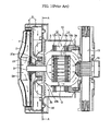
- Fig. 1 is a sectional view illustrating another conventional centrifugal blower for a vacuum cleaner.
- Fig. 2 is a perspective view illustrating a diffuser included in the conventional centrifugal blower.
- Fig. 3 is a cross-sectional view taken along the line A - A of Fig. 1 .
- the conventional centrifugal blower for a vacuum cleaner includes an impeller 4 rotatably installed in an impeller housing 2 provided at a front end thereof with a suction port 2a, and a motor 10 installed in a motor housing 3, and adapted to rotate the impeller 4.
- the motor housing 3 is coupled at a front end thereof to a rear end of the impeller housing 2, and provided at side portions thereof with a plurality of discharge ports 3a.
- a diffuser 8 is installed between the impeller 4 and the motor 10. As shown in Figs. 2 and 3 , the diffuser 8 is provided at its front surface with diffuser vanes 6 for feeding air discharged from the outlet of the impeller 4 in a pressurized state. The diffuser 8 is also provided at its rear surface with guide vanes 7 for guiding the pressurized air fed by the diffuser vanes 6 to the motor 10.
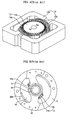
- Fig. 4 is a perspective view illustrating the motor of the conventional centrifugal blower used for vacuum cleaners.
- Fig. 5 is a plan view illustrating a bearing supporter mounted to the motor of the conventional centrifugal blower.
- the motor which is denoted by the reference numeral 10, includes a stator 12 having a field core 12a fixedly mounted to an inner wall of the motor housing 3, and a field coil 12b wound around the field core 12a.
- the motor 10 also includes a rotor 14 having an armature core 14a mounted to a rotating shaft 9 connected to the impeller 4 while being inwardly spaced apart from the rotor 12, and an armature coil 14b wound around the armature core 14a.
- the motor 10 further includes a brush 15, and a commutator 16 which are arranged at the rear of the rotor 14, that is, connected to a rear end of the rotating shaft 9, in order to supply external electric power to the field coil 12b and the armature coil 14b.
- An air gap G with a desired dimension is defined between the stator 12 and the rotor 14.
- the motor 10 having the above mentioned configuration is driven by single-phase power.
- current flows through the field coil 12b and armature coil 14b in accordance with serial connection of the field coil 12b, brush 15, commutator 16, and armature coil 14b to the single-phase power magnetic flux is generated at the field coil 12b and armature coil 14b.
- Air passing through the impeller 4 and diffuser 8 is collected by an air collecting plate 20 which, in turn, discharges the collected air in a concentrated fashion toward the air gap G defined between the stator 12 and the rotor 14 via cooling holes 20a and 20b formed at the air collecting plate 20, and toward the rotor 14, thereby cooling the motor 10. After cooling the motor 10, the air is outwardly discharged through the discharge ports 3a of the motor housing 3.
- the air emerging from the impeller 4 and diffuser 8 is discharged in a concentrated fashion toward the air gap G defined between the stator 12 and the rotor 14 by the air collecting plate 20, the rotor 14 generating a relatively large amount of heat during operation of the motor 10 is insufficiently cooled because the armature coil 14b is shielded by a bearing supporter 22 arranged between the impeller housing 2 and the motor housing 3 to support a bearing 23 for rotatably supporting the rotating shaft 9 of the motor 10, as shown in Fig. 5 .
- the armature coil 14b of the rotor 14 is excessively increased in temperature, so that the cooling characteristics of the armature coil 14b are degraded, thereby causing a degradation in the reliability of the motor 10. Furthermore, the life span of the motor 10 is reduced. In order to extend the life span of the motor 10, it is necessary to improve the insulation grade of the motor 10. For example, the material of the armature coil 14b should be replaced. Thus, there is a problem of inconvenience.
- an object of the invention is to provide a centrifugal blower for a vacuum cleaner in which air passing through an impeller and a diffuser is blown toward the armature coil of a rotor having great influence on the reliability and life span of a motor including the rotor, thereby being capable of achieving an improvement in the reliability of the motor while extending the life span of the motor.
- Another object of the invention is to provide a centrifugal blower for a vacuum cleaner in which air fed toward a motor included in the blower is allowed to mainly pass through the rotor even when the rotor of the motor rotates at high speed, thereby being capable of achieving an enhancement in motor cooling efficiency while reducing the insulation grade of the motor.
- a centrifugal blower for a vacuum cleaner comprises a motor including a stator, and a rotor rotatably installed in the stator; an impeller connected with the rotor by a rotating shaft, and adapted to rotate in accordance with a drive force received from the motor via the rotating shaft, thereby sucking air; a diffuser installed between the motor and the impeller, the diffuser having guide vanes adapted to guide air discharged from the impeller toward the motor; and guide means for guiding the air emerging from the guide vanes toward the rotor of the motor.
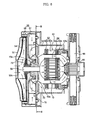
- Fig. 6 is a sectional view illustrating a centrifugal blower for a vacuum cleaner according to the present invention.
- Fig. 7 is a perspective view illustrating a diffuser included in the centrifugal blower according to the present invention.
- Fig. 8 is a cross-sectional view taken along the line B - B of Fig. 6 .
- Fig. 9 is a perspective view illustrating a motor included in the centrifugal blower according to the present invention.
- Fig. 10 is a plan view illustrating a bearing supporter mounted to the motor of the centrifugal blower according to the present invention.
- Fig. 11 is a sectional view illustrating the bearing supporter according to the present invention.
- the centrifugal blower for vacuum cleaners includes an impeller housing 52 centrally provided at a front wall thereof with a suction port 52a, an impeller 54 rotatably installed in the impeller housing 52, and adapted to suck air from the suction port 52a, a motor housing 53 connected at a front wall thereof to a rear wall of the impeller housing 52, and provided at side walls thereof with a plurality of discharge ports 53a, and a motor 60 installed in the motor housing 53, and adapted to rotate the impeller 54.
- the motor 60 includes a stator 62, and a rotor 64.
- the centrifugal blower also includes a diffuser 58 installed between the impeller 54 and the motor 60, and adapted to guide air discharged from the impeller 54 toward the motor 60 while increasing the pressure of the air, and a guide means for guiding the air emerging from the diffuser 58 toward the rotor 64 in a concentrated fashion.
- the diffuser 58 is provided at its front surface with diffuser vanes 56 for increasing the pressure of air emerging from the outlet of the impeller 54.
- the diffuser 58 is also provided at its rear surface with guide vanes 7 for guiding the pressurized air fed by the diffuser vanes 56 to the motor 60.
- the motor 60 includes a stator 62 having a field core 62a fixedly mounted to an inner wall of the motor housing 53, and a field coil 62b wound around the field core 62a.
- the motor 60 also includes a rotor 64 having an armature core 64a mounted to a rotating shaft 59 connected to the impeller 54, and an armature coil 64b wound around the armature core 64a.
- the motor 10 further includes a brush 65, and a commutator 66 which are arranged at the rear of the rotor 64, that is, connected to a rear end of the rotating shaft 59, in order to supply external electric power to the field coil 62b and the armature coil 64b.
- An air gap G is defined between the stator 62 and the rotor 64.
- a bearing supporter 72 is arranged between the impeller housing 52 and the motor housing 53 to support a bearing 73 for rotatably supporting the rotating shaft 59 of the motor 60.
- An air collecting plate 70 is also installed between the bearing supporter 72 and the motor housing 53. The air collecting plate 70 collects air fed toward the motor 60 after emerging from the impeller 54, and discharges the collected air toward the air gap G defined between the stator 62 and the rotor 64 in a concentrated fashion.
- the air collecting plate 70 is provided at its central portion with a cooling hole 70a opened to the front surface of the rotor 64, and at its opposite lateral portions with cooling holes 70b opened to the air gap G.
- the guide means comprises holes 82 formed at the bearing support 72, and opened to the front surface of the rotor 64, air guides 57a adapted to guide air discharged from the guide vanes 57 to the holes 82, and guide portions 86 each formed at the bearing supporter 72 to have a structure bent toward an associated one of the holes 82 by a desired angle ⁇ , and adapted to guide air emerging from the associated hole 82 to the rotor 64.
- the guide means has two holes 82 respectively formed at opposite portions of the bearing support 72.
- the holes 82 may have diverse shapes, for example, a rectangular shape, or an arc shape with a desired width.
- Each of the air guides 57a is provided by extending the tip of a selected one of the guide vanes 57 toward the center of the diffuser 58 so as to guide air guided by the selected guide vane 57 to the holes 82.
- a plurality of guide vanes 57 are arranged at the rear surface of the diffuser 58 around the rotating shaft 59 while being uniformly spaced from one another in a circumferential direction, and having a structure curved in the clockwise direction.
- the air guides 57a are formed by extending, toward the holes 82, respective outlet ends of the guide vanes 57 positioned near those holes 82.
- each guide portion 86 is rearwardly inclined toward the rotor 64 while having an inclined angle ⁇ of 0 to 70 ° with respect to the surface of the bearing supporter 72.
- the motor 60 includes two poles 62a' protruded from the inner surface of the field core 62a while facing each other.
- the field coils 62b are wound around the poles 62a', respectively.
- the motor 60 also includes air guide members 88 mounted to inner surface portions of the field core 62a not formed with the poles 62a'. Each of the air guide members 88 prevents air fed toward the rotor 64 from being moved toward the stator 12 without reaching the rotor as the rotor 14 rotates at high speed, so as to allow the air to be effectively guided to the rotor 64.
- the air guide members 88 are arranged at the portions of the field core 62a not formed with the poles 62a' while facing each other.
- Each air guide member 88 has a convex central portion, and opposite ends fixedly mounted to the inner surface of the field core 62a.
- each air guide member 88 is arranged between the stator 62 and rotor 64 generating interacting electromagnetic forces, it should be made of an insulating material.
- the air fed toward the rotor 64 is reliably guided to pass through the rotor 64 even when the rotor 64 rotates at high speed.
- the rotor 64 is effectively cooled.
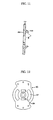
- Fig. 12 is a plan view illustrating a bearing supporter plate according to an embodiment of the present invention.
- Fig. 13 is a plan view illustrating a bearing supporter plate according to another embodiment of the present invention.
- Fig. 12 The embodiment of Fig. 12 is associated with a bearing supporter plate 90 in which the above described bearing supporter and air collecting plate are integral with each other.
- the bearing supporter plate 90 is provided at its left and right portions with first holes 92 for discharging a part of air emerging from the guide vanes 57 toward the stator 62 of the motor 60, and at its upper and lower portions with second holes 94 for discharging the remaining part of the air emerging from the guide vanes 57 toward the rotor 64.
- a pair of first holes 92 are symmetrically arranged around the rotating shaft 59.
- a pair of second holes 94 are symmetrically arranged around the rotating shaft 59.
- Each first hole 92 has an arc shape with a desired width, whereas each second hole 94 has a rectangular shape with a desired width.
- the first holes 92 are radially spaced from the center of the rotating shaft 59 by a distance longer than that of the second holes 94 from the center of the rotating shaft 59.
- a part of the air discharged from the guide vanes 57 is guided by the air guides 57a to enter the holes 82 formed at the bearing supporter 72, and then discharged toward the rotor 64 in a concentrated fashion along the guide portions 86 formed at the holes 82.
- the remaining air part guided along the guide vanes 57 without being guided by the air guides 57a is collected by the air collecting plate 70 while being increased in pressure.
- the collected air is discharged at high speed toward the air gap G defined between the stator 62 and the rotor 64 via the cooling holes 70a and 70b formed at the air collecting plate 70, and toward the rotor 64.
- the air discharged toward the rotor 64 tends to move radially outwardly due to a centrifugal force generated as the rotor 64 rotates at high speed, it is guided to pass through the rotor 64 without flowing toward the stator 62 by virtue of the poles 62a' and air guide members 88 arranged around the rotor 64.
- the rotor 64 is effectively cooled in a concentrated fashion.
- the air discharged toward the air gap G defined between the stator 62 and the rotor 64 cools both the stator 62 and the rotor 64, thereby preventing the motor 60 from overheating.
- the present invention provides a centrifugal blower for a vacuum cleaner in which air passing through an impeller and a diffuser is guided to holes and guide portions formed at a bearing supporter by air guides, so that it is discharged toward the armature coil of a rotor having great influence on the reliability and life span of a motor including the rotor, thereby being capable of achieving an improvement in the reliability of the motor while extending the life span of the motor.
- air fed toward the motor is allowed to mainly pass through the rotor even when the rotor rotates at high speed. Accordingly, it is possible to achieve an enhancement in motor cooling efficiency while reducing the insulation grade of the motor.
Claims (15)
- Zentrifugalgebläse für einen Staubsauger, das umfasst:- einen Motor (60), der einen Stator (62) und einen im Stator (62) drehbar installierten Rotor (64) enthält;- ein Laufrad (54), das mit dem Rotor (64) durch eine Drehwelle (59) verbunden ist und dazu ausgelegt ist, sich entsprechend einer Antriebskraft, die vom Motor (60) über die Antriebswelle (59) aufgenommen wird, zu drehen, um dadurch Luft anzusaugen;- einen Diffusor (58), der zwischen dem Motor (60) und dem Laufrad (54) installiert ist, wobei der Diffusor Führungsschaufeln (57) besitzt, die dazu ausgelegt sind, die vom Laufrad (54) geförderte Luft zum Motor (60) zu führen; und- eine Lagerunterstützung (72), die zwischen dem Diffusor (58) und dem Motor (60) installiert ist, wobei die Lagerunterstützung (72, 90, 100) Löcher (82) besitzt, um die von den Führungsschaufeln (57) austretende Luft zum Rotor des Motors (60) zu führen,dadurch gekennzeichnet, dass
wenigstens eines der Löcher (82) so ausgebildet ist, dass es in die vordere Oberfläche des Rotors (64) mündet, so dass die von den Führungsschaufeln (57) des Diffusors (58) austretende Luft zum Rotor (64) gefördert wird. - Zentrifugalgebläse nach Anspruch 1, wobei die Lagerunterstützung (72) ein mittiges Loch besitzt, in das ein um die Drehwelle (59) angebrachtes Lager (73) eingesetzt ist.
- Zentrifugalgebläse nach Anspruch 1, wobei das Loch (82) eine rechtwinklige Form hat.
- Zentrifugalgebläse nach Anspruch 1, wobei das Loch (62) eine Bogenform mit einer gewünschten Breite hat.
- Zentrifugalgebläse nach Anspruch 1, wobei die Anzahl der Löcher (62) gleich zwei ist und die Löcher (62) um ein Zentrum der Lagerunterstützung (72) symmetrisch angeordnet sind.
- Zentrifugalgebläse nach Anspruch 1, das ferner Führungsabschnitte (86) umfasst, wovon jeder an der Lagerunterstützung (72) so ausgebildet ist, dass er eine Struktur besitzt, die zu einem Zugeordneten der Löcher (82) um einen gewünschten Winkel gebogen ist, und dazu ausgelegt ist, die von dem zugeordneten Loch (82) austretende Luft zum Rotor (64) zu führen.
- Zentrifugalgebläse nach Anspruch 6, wobei jeder der Führungsabschnitte (86) zum Rotor (64) geneigt ist und dabei einen Neigungswinkel im Bereich von 0 bis 70° in Bezug auf eine Hauptoberfläche der Lagerunterstützung (72) besitzt.
- Zentrifugalgebläse nach Anspruch 1, wobei der Diffusor (57) ferner Luftführungen (57a) besitzt, die dazu ausgelegt sind, Luft zu dem Loch (82) zu führen.
- Zentrifugalgebläse nach Anspruch 8, wobei die Luftführungen (57a) durch Verlängern jeweiliger Spitzen ausgewählter Führungsschaufeln zum Loch (62) gebildet sind, wobei die ausgewählten Führungsschaufeln (57a) wenigstens einen Teil aller Führungsschaufeln (57) bilden.
- Zentrifugalgebläse nach Anspruch 1, wobei wenigstens ein Loch (94, 104) zum Stator (62) geöffnet ist.
- Zentrifugalgebläse nach Anspruch 10, wobei die Löcher (94, 104), die so geformt sind, dass sie zum Stator (62) geöffnet sind, um das Zentrum der Lagerunterstützung (90, 100) symmetrisch angeordnet sind.
- Zentrifugalgebläse nach Anspruch 10, wobei die Löcher (94, 104), die so geformt sind, dass sie zum Stator geöffnet sind, eine Bogenform mit einer gewünschten Breite haben.
- Zentrifugalgebläse nach Anspruch 1, wobei der Motor (60) mit Luftführungselementen (88) versehen ist, um Luft, die zwischen den Stator (62) und den Rotor (64) eingeleitet wird, so zu führen, dass sie sich durch den Rotor (64) bewegt, ohne zum Stator (62) zu strömen.
- Zentrifugalgebläse nach Anspruch 13, wobei jedes der Luftführungselemente (88) einen konvexen Mittelabschnitt und gegenüberliegende Enden, die am Stator (62) fest montiert sind, besitzt.
- Zentrifugalgebläse nach Anspruch 13, wobei jedes der Luftführungselemente (88) aus einem Isoliermaterial hergestellt ist.
Applications Claiming Priority (6)
| Application Number | Priority Date | Filing Date | Title |
|---|---|---|---|
| KR10-2001-0059485A KR100438292B1 (ko) | 2001-09-26 | 2001-09-26 | 청소기 모터 방열구조 |
| KR2001059485 | 2001-09-26 | ||
| KR2002000253 | 2002-01-03 | ||
| KR10-2002-0000253A KR100445649B1 (ko) | 2002-01-03 | 2002-01-03 | 진공청소기용 모터 |
| KR2002000250 | 2002-01-03 | ||
| KR10-2002-0000250A KR100437036B1 (ko) | 2002-01-03 | 2002-01-03 | 청소기용 원심송풍기 |
Publications (3)
| Publication Number | Publication Date |
|---|---|
| EP1297772A2 EP1297772A2 (de) | 2003-04-02 |
| EP1297772A3 EP1297772A3 (de) | 2003-08-13 |
| EP1297772B1 true EP1297772B1 (de) | 2010-03-31 |
Family
ID=27350526
Family Applications (1)
| Application Number | Title | Priority Date | Filing Date |
|---|---|---|---|
| EP20020013503 Expired - Fee Related EP1297772B1 (de) | 2001-09-26 | 2002-06-17 | Kreiselgebläse für Staubsauger |
Country Status (2)
| Country | Link |
|---|---|
| EP (1) | EP1297772B1 (de) |
| DE (1) | DE60235788D1 (de) |
Families Citing this family (6)
| Publication number | Priority date | Publication date | Assignee | Title |
|---|---|---|---|---|
| GB0328384D0 (en) * | 2003-12-06 | 2004-01-14 | Johnson Electric Sa | Blower motor |
| KR20060007637A (ko) * | 2004-07-20 | 2006-01-26 | 엘지전자 주식회사 | 진공청소기용 팬-모터의 가이드 베인 구조 |
| CN1900616B (zh) * | 2005-07-19 | 2010-12-22 | 乐金电子(天津)电器有限公司 | 送风装置 |
| GB2467968B (en) * | 2009-02-24 | 2015-04-22 | Dyson Technology Ltd | Centrifugal compressor with a diffuser |
| AU2012292950B2 (en) | 2011-08-05 | 2015-10-29 | Resmed Motor Technologies Inc. | Blower |
| US9243844B2 (en) | 2014-03-28 | 2016-01-26 | General Electric Company | Dryer appliance with an impeller assembly |
Family Cites Families (4)
| Publication number | Priority date | Publication date | Assignee | Title |
|---|---|---|---|---|
| JP3216988B2 (ja) * | 1996-04-26 | 2001-10-09 | 株式会社日立製作所 | 電気掃除機及び電気掃除機用電動送風機 |
| JPH10231799A (ja) * | 1998-03-16 | 1998-09-02 | Hitachi Ltd | 電気掃除機及び電動送風機 |
| US6166462A (en) * | 1998-05-04 | 2000-12-26 | Ametek, Inc. | Bypass motor/fan assembly having separate working air passages |
| AU4671599A (en) * | 1999-05-31 | 2000-12-18 | Turk Elektrik Endustrisi A.S. | Wet and dry electrical vacuum cleaner motor with reduced balance problems arising from assembly |
-
2002
- 2002-06-17 DE DE60235788T patent/DE60235788D1/de not_active Expired - Lifetime
- 2002-06-17 EP EP20020013503 patent/EP1297772B1/de not_active Expired - Fee Related
Also Published As
| Publication number | Publication date |
|---|---|
| EP1297772A3 (de) | 2003-08-13 |
| EP1297772A2 (de) | 2003-04-02 |
| DE60235788D1 (de) | 2010-05-12 |
Similar Documents
| Publication | Publication Date | Title |
|---|---|---|
| CN108953229B (zh) | 送风装置以及吸尘器 | |
| US7845917B2 (en) | Electric blower | |
| EP1450468B1 (de) | Motor und Waschmaschine welche diesen Motor beinhaltet | |
| JP7090767B2 (ja) | モータ、送風機、電気掃除機および手乾燥装置 | |
| CN111869050B (zh) | 定子、电动机、电动吸尘器以及手干燥装置 | |
| CN111622984B (zh) | 送风装置及吸尘器 | |
| EP1617083B1 (de) | Elektrisch angetriebene Pumpe | |
| EP1297772B1 (de) | Kreiselgebläse für Staubsauger | |
| EP3760878B1 (de) | Elektrisches gebläse, elektrischer staubsauger und handtrockner | |
| JP4951588B2 (ja) | 電動送風機及びこれを備えた電気掃除機 | |
| CN213953999U (zh) | 送风装置及吸尘器 | |
| EP4148961A1 (de) | Motoranordnung | |
| KR100438292B1 (ko) | 청소기 모터 방열구조 | |
| GB2362268A (en) | Stator winding mounting/windage reduction in an electric machine | |
| CN111630751B (zh) | 定子、电机、送风机、电动吸尘器及手干燥装置 | |
| JP4269707B2 (ja) | 整流子電動機 | |
| CN209743186U (zh) | 送风装置以及具有该送风装置的吸尘器 | |
| US11454246B2 (en) | Electric blower, vacuum cleaner, and hand drying device | |
| CN111749911A (zh) | 送风装置和吸尘器 | |
| JPH10290551A (ja) | モーター | |
| WO2023162284A1 (ja) | 電動送風機、および、それを用いた電気掃除機 | |
| CN220527811U (zh) | 离心式吸尘电机 | |
| KR100437036B1 (ko) | 청소기용 원심송풍기 | |
| KR100680192B1 (ko) | 진공청소기용 모터 | |
| JP2007270633A (ja) | 電動送風機及び電気掃除機 |
Legal Events
| Date | Code | Title | Description |
|---|---|---|---|
| PUAI | Public reference made under article 153(3) epc to a published international application that has entered the european phase |
Free format text: ORIGINAL CODE: 0009012 |
|
| AK | Designated contracting states |
Kind code of ref document: A2 Designated state(s): AT BE CH CY DE DK ES FI FR GB GR IE IT LI LU MC NL PT SE TR |
|
| AX | Request for extension of the european patent |
Extension state: AL LT LV MK RO SI |
|
| RIN1 | Information on inventor provided before grant (corrected) |
Inventor name: REW, HO SEON Inventor name: LEE, YOUNG WOO |
|
| PUAL | Search report despatched |
Free format text: ORIGINAL CODE: 0009013 |
|
| AK | Designated contracting states |
Designated state(s): AT BE CH CY DE DK ES FI FR GB GR IE IT LI LU MC NL PT SE TR |
|
| AX | Request for extension of the european patent |
Extension state: AL LT LV MK RO SI |
|
| 17P | Request for examination filed |
Effective date: 20030912 |
|
| AKX | Designation fees paid |
Designated state(s): DE FR GB IT |
|
| 17Q | First examination report despatched |
Effective date: 20070809 |
|
| GRAP | Despatch of communication of intention to grant a patent |
Free format text: ORIGINAL CODE: EPIDOSNIGR1 |
|
| GRAS | Grant fee paid |
Free format text: ORIGINAL CODE: EPIDOSNIGR3 |
|
| GRAA | (expected) grant |
Free format text: ORIGINAL CODE: 0009210 |
|
| AK | Designated contracting states |
Kind code of ref document: B1 Designated state(s): DE FR GB IT |
|
| REG | Reference to a national code |
Ref country code: GB Ref legal event code: FG4D |
|
| REF | Corresponds to: |
Ref document number: 60235788 Country of ref document: DE Date of ref document: 20100512 Kind code of ref document: P |
|
| PLBE | No opposition filed within time limit |
Free format text: ORIGINAL CODE: 0009261 |
|
| STAA | Information on the status of an ep patent application or granted ep patent |
Free format text: STATUS: NO OPPOSITION FILED WITHIN TIME LIMIT |
|
| 26N | No opposition filed |
Effective date: 20110104 |
|
| PGFP | Annual fee paid to national office [announced via postgrant information from national office to epo] |
Ref country code: FR Payment date: 20140513 Year of fee payment: 13 Ref country code: IT Payment date: 20140618 Year of fee payment: 13 |
|
| PG25 | Lapsed in a contracting state [announced via postgrant information from national office to epo] |
Ref country code: IT Free format text: LAPSE BECAUSE OF NON-PAYMENT OF DUE FEES Effective date: 20150617 |
|
| REG | Reference to a national code |
Ref country code: FR Ref legal event code: ST Effective date: 20160229 |
|
| PG25 | Lapsed in a contracting state [announced via postgrant information from national office to epo] |
Ref country code: FR Free format text: LAPSE BECAUSE OF NON-PAYMENT OF DUE FEES Effective date: 20150630 |
|
| PGFP | Annual fee paid to national office [announced via postgrant information from national office to epo] |
Ref country code: DE Payment date: 20160511 Year of fee payment: 15 Ref country code: GB Payment date: 20160511 Year of fee payment: 15 |
|
| REG | Reference to a national code |
Ref country code: DE Ref legal event code: R119 Ref document number: 60235788 Country of ref document: DE |
|
| GBPC | Gb: european patent ceased through non-payment of renewal fee |
Effective date: 20170617 |
|
| PG25 | Lapsed in a contracting state [announced via postgrant information from national office to epo] |
Ref country code: GB Free format text: LAPSE BECAUSE OF NON-PAYMENT OF DUE FEES Effective date: 20170617 Ref country code: DE Free format text: LAPSE BECAUSE OF NON-PAYMENT OF DUE FEES Effective date: 20180103 |