EP1297301B1 - A cargo unit for submunitions - Google Patents
A cargo unit for submunitions Download PDFInfo
- Publication number
- EP1297301B1 EP1297301B1 EP01941433A EP01941433A EP1297301B1 EP 1297301 B1 EP1297301 B1 EP 1297301B1 EP 01941433 A EP01941433 A EP 01941433A EP 01941433 A EP01941433 A EP 01941433A EP 1297301 B1 EP1297301 B1 EP 1297301B1
- Authority
- EP
- European Patent Office
- Prior art keywords
- submunitions
- mode
- target
- penetrator
- function
- Prior art date
- Legal status (The legal status is an assumption and is not a legal conclusion. Google has not performed a legal analysis and makes no representation as to the accuracy of the status listed.)
- Expired - Lifetime
Links
- 238000000926 separation method Methods 0.000 claims description 23
- 230000035515 penetration Effects 0.000 claims description 14
- 239000006185 dispersion Substances 0.000 claims description 4
- 230000001419 dependent effect Effects 0.000 claims description 3
- 238000000034 method Methods 0.000 description 6
- 230000000694 effects Effects 0.000 description 2
- 239000002360 explosive Substances 0.000 description 2
- 230000000977 initiatory effect Effects 0.000 description 2
- 230000000149 penetrating effect Effects 0.000 description 2
- 241000273930 Brevoortia tyrannus Species 0.000 description 1
- 230000002301 combined effect Effects 0.000 description 1
- 238000004891 communication Methods 0.000 description 1
- 239000000470 constituent Substances 0.000 description 1
- 238000005474 detonation Methods 0.000 description 1
- 238000010586 diagram Methods 0.000 description 1
- 230000009977 dual effect Effects 0.000 description 1
- 239000012634 fragment Substances 0.000 description 1
- 230000014509 gene expression Effects 0.000 description 1
- 239000008188 pellet Substances 0.000 description 1
- 230000001960 triggered effect Effects 0.000 description 1
Images




Classifications
-
- F—MECHANICAL ENGINEERING; LIGHTING; HEATING; WEAPONS; BLASTING
- F42—AMMUNITION; BLASTING
- F42B—EXPLOSIVE CHARGES, e.g. FOR BLASTING, FIREWORKS, AMMUNITION
- F42B12/00—Projectiles, missiles or mines characterised by the warhead, the intended effect, or the material
- F42B12/02—Projectiles, missiles or mines characterised by the warhead, the intended effect, or the material characterised by the warhead or the intended effect
- F42B12/36—Projectiles, missiles or mines characterised by the warhead, the intended effect, or the material characterised by the warhead or the intended effect for dispensing materials; for producing chemical or physical reaction; for signalling ; for transmitting information
- F42B12/56—Projectiles, missiles or mines characterised by the warhead, the intended effect, or the material characterised by the warhead or the intended effect for dispensing materials; for producing chemical or physical reaction; for signalling ; for transmitting information for dispensing discrete solid bodies
- F42B12/58—Cluster or cargo ammunition, i.e. projectiles containing one or more submissiles
Definitions
- the present invention relates to a cargo device that carries a number of submunitions whereby the cargo device is preferably equipped with guidance and/or target seeking functions and may constitute a missile or a missile or equivalent, launchable from a ramp or other weapon platform in the form of, for example, an aircraft.
- the triggering or actuation of the submunitions carried shall then be determinable by a programming function on the ground or on board the weapon platform in question, such as an aircraft, or via a fixed or wireless communication link from the ground or on board said weapon platform.
- the submunitions shall, moreover, be actuatable either individually or jointly by means of or via an impact function, proximity fuze, remote triggering, or by another admittedly known triggering device.
- the measures and ammunition units proposed must also satisfy the stringent requirements pertaining to handling, service and storage, and the matter must be characterised by singularity of purpose while safety during handling and operation must not be neglected.
- the objective of the present invention is to resolve this problem completely or partially.
- the feature that can be considered to be the main characteristic for the initially mentioned cargo device is, among other things, that the programming function incorporated comprises or interacts with mode determining devices which, for example, dependent on at least one manual or automatic actuation enables the cargo device and its submunitions to act either jointly in a penetrator mode in which the submunitions are at least essentially conjoined in a joint triggering or actuation function, or in a separation mode in which the submunitions sequentially exit their cargo space in the device and subsequently function via an individual triggering or actuation function whereby the said triggering or actuation function in each submunition can be independent of or co-ordinated with the triggering or actuation function of the other submunitions.
- mode determining devices which, for example, dependent on at least one manual or automatic actuation enables the cargo device and its submunitions to act either jointly in a penetrator mode in which the submunitions are at least essentially conjoined in a joint triggering or actuation function, or in a
- the same submunitions can be utilised in either mode.
- the direction of the submunitions can be determined on the ground before the cargo device starts its journey to the target, whereby the submunitions are further matched to the target and are arranged to be either conjoined in the device or for dispersal from the device according to the mode employed.
- the basic principle behind the present invention is thus ⁇ as the expressions 'penetrator mode' and 'separation mode' indicate ⁇ that if penetrator mode is selected all the submunitions shall be tightly conjoined to form a single body whose combined effect provides good penetration capability in hard targets such as bunkers and which, when the cargo device reaches the target and more or less itself disintegrates against the target the conjoined submunitions continue into the target where they detonate and blow up the target from inside, or blow up the target on impact.
- the mode determining devices ⁇ dependent on an additional actuation ⁇ can even be arranged to enable the cargo device and its submunitions to operate with a distributed penetrator mode in which the submunitions achieve a minor sequential dispersal and are actuated as penetration of the target progresses.
- the submunitions are dispersed on command over a pre-determined target zone, and each submunition is thus actuated by its own initiation device that can be time controlled, point detonating, or have its own elementary target seeker or proximity fuze.
- the separation mode can be a good alternative when engaging enemy forces attacking in light armour vehicles, for example.
- the cargo device can even continue its flight after releasing all its submunitions. In this case the dedicated, joint nose section for penetrator mode remains in the cargo device. Dispersal of the submunitions utilises already known techniques.
- Number 1 in Figure 1 denotes a cargo device in the form of a missile, for example.
- the basic design of the missile or equivalent is already well known and will not be described herein.
- Figure 1 illustrates the case where the missile operates in a penetrator mode, which means that it shall impact with a target M, in the form of a bridge pier for example, and effect a hole in the target.
- the missile or equivalent carries or contains a number of submunitions 2 of an already known type.
- the submunitions may comprise explosive charges with possible associated fragment and pellet elements, or submunitions with shaped charge effect, etc. In this case the relation of the submunitions 2 to each other is selected according to the type of target represented by M.
- the submunitions are conjoined together in the manner characteristic of the penetrator mode.
- the position of the submunitions inside the cargo device is shown in Figure 4 by the designation 10" and their joint reinforced nose section 10' is also visible, arranged in front of the submunitions where it is mainly responsible for penetrating the target before the various submunitions detonate inside the target or complete the penetration of the target.
- the cargo device which has completed its task by transporting the submunitions to the target, and which does not have the strength or hardness of the said reinforced nose section, will in most cases be simultaneously completely destroyed against the outer wall of the target while the submunitions, preceded by their reinforced nose section 10', thus continue into the target.
- Figure 2 represents in general the same cargo device described in Figure 1.
- the missile or equivalent is designated 1'.
- the missile or equivalent is operating in a separation mode whereby the cargo device when close to the target dispenses submunitions 2, 2', 2", 2"', etc above or adjacent to an actual target such as a military detachment or equivalent that is not illustrated in Figure 2.
- the submunitions thereby leave their cargo space inside the missile or equivalent sequentially to enable an effective dispersion over the target in question.
- the dispersion can be varied via different program modes controlling the release of the submunitions from the missile or equivalent.
- Such program modes can be achieved by employing an already known method such as time controlled circuits.
- Figure 3 illustrates the case when the cargo device operates with a distributed penetrator method in which the cargo device 1 " on an approach path 3 pierces and penetrates a building 4 that can have a number of internal confined spaces or rooms of which rooms 4a, 4b, and 4c are designated on Figure 3. It can thus be expected that penetration in the target will be performed primarily by the conjoined submunitions preceded by their common reinforced nose section.
- the said confined spaces in the building are bounded in a known manner by walls etc 4a', 4a", 4b', 4b", 4c', 4c" and so on.
- cargo device 1" ⁇ or at least the submunitions incorporated ⁇ penetrate the said walls etc, and by using other approach paths into building 4 different walls, floors and ceilings can be penetrated.
- the submunitions shall be dispensed into the various rooms or confined spaces 4a, 4b, 4c as the penetration of the building and its various rooms progresses.
- submunitions have been dispensed from the missile into rooms 4a, 4b, and 4c resulting in bursts or triggerings symbolised by 5, 6 and 7.
- Figure 4 shows a cargo device in the form of a missile 1"' of an already well known type.
- the missile is equipped with target seeking and guidance system equipment 8, 9, a motor arrangement, control surfaces, etc.
- Figure 5 shows a stowage compartment 10 for submunitions that can be arranged for external release 11 of submunitions. Control of the triggering or actuation and possible release of the submunitions in distribution or separation modes is described in outline below.
- the submunitions 10" are located inside the stowage compartment 10 arranged conjoined behind each other and behind the common reinforced nose section 10' located at the front of the said compartment in the direction of flight of the carrier.
- penetrator mode they function during penetration of the target as a collective body but which, in distribution mode, is divided into its constituent parts ⁇ i.e. the individual submunitions ⁇ after which they are dispensed in accordance with the desired dispersion pattern.
- Locking devices can thereby be actuated manually or automatically via electrical control so that either mode can be enabled in conjunction with the cargo device's or vehicle's path towards the target in question.
- Actuation of the locking devices for locking in penetrator mode or opening in separation mode can be carried out on the ground, by wireless link from the ground, or by the weapon platform carrying the cargo device such as an aircraft, etc.
- the locking devices can be set or actuated before the cargo device is launched.
- the cargo device can in principle be loaded with different submunitions whereby the first type of submunitions are so arranged in the cargo device's cargo space that they cannot be separated, or in such a way that they can be separated. Opening of the locking devices and dispersal of the submunitions in the distributed penetrator mode can be performed in a corresponding manner to that for the separation mode. The only difference is that the sequential release of the submunitions from the cargo device shall be with closer intervals.
- two submunitions 11' and 11" are arranged in cargo device 1"". More submunitions are incorporated but are not illustrated in Figure 6.
- the submunitions as such can be constructed in an already known manner.
- the submunitions are conjoined by symbolically designated locking devices 12. These locking devices can be replaced by a tubular shaped outer casing that is gradually consumed during the penetrator mode, and from which the submunitions are successively ejected rearwards during the distribution mode.
- Figure 7 shows a submunition 11'" released from cargo device 1""'. It has been ejected rearwards from the tubular shaped carrier fuselage. Symbolically designated locking devices 12' are also shown in open or release position.
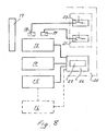
- Figure 8 a number of submunitions 13, 14, 15, 16 are arranged in a symbolically displayed unit 17.
- Figure 8 also includes symbolically illustrated locking devices 18 and 19.
- Locking device 18 is controllable from a control unit 20 which, when in non-actuated mode, keeps the locking devices open thereby enabling the above mentioned separation mode.
- For closed mode an actuation signal is received that actuates locking device 18 which thereby prevents the submunitions from leaving the cargo device 17, thus enabling penetrator mode.
- Locking device 19 operates in the same way as locking device 18 in the distributed penetrator mode.
- Locking device 19 is controllable from control unit 21.
- a programming device is designated 22, and there is a control unit designated 23 to control the programming device.
- the programming device in question is used to determine the triggering and actuation functions for the submunitions.
- the above mentioned control unit can be incorporated in a common unit 24.
- each of these submunitions has a strong tubular shaped outer casing generally designated 28'-31', where each outer casing has a somewhat thinner walled front section 28"-31" that is bevelled under the rear section of the rear casing wall of the preceding submunition.
- the submunitions are conjoined by modified ball catches 28"'-31"' and are further equipped with integral initiation functions 28""-31”” that have the dual task of releasing the submunitions from each other in separation mode.
- each submunition 28-31 is filled with explosive.
- Figure 10 shows submunition 28 suspended from its parachute after a completed separation mode, descending towards the target zone where it will be triggered either by impact or by another ⁇ admittedly known ⁇ initiation function.
Landscapes
- Engineering & Computer Science (AREA)
- Chemical & Material Sciences (AREA)
- Combustion & Propulsion (AREA)
- General Engineering & Computer Science (AREA)
- Aiming, Guidance, Guns With A Light Source, Armor, Camouflage, And Targets (AREA)
- Radar Systems Or Details Thereof (AREA)
- Control Of Position, Course, Altitude, Or Attitude Of Moving Bodies (AREA)
Description
- The present invention relates to a cargo device that carries a number of submunitions whereby the cargo device is preferably equipped with guidance and/or target seeking functions and may constitute a missile or a missile or equivalent, launchable from a ramp or other weapon platform in the form of, for example, an aircraft. The triggering or actuation of the submunitions carried shall then be determinable by a programming function on the ground or on board the weapon platform in question, such as an aircraft, or via a fixed or wireless communication link from the ground or on board said weapon platform. The submunitions shall, moreover, be actuatable either individually or jointly by means of or via an impact function, proximity fuze, remote triggering, or by another admittedly known triggering device.
- The designing of missiles and other ammunition or cargo-bearing devices so that they are specially suited to combating targets or situations of a certain given type is previously known. This means that the ammunition or warhead designed for a specific type of target is often completely unsuitable for combating a different type of target, and vice versa. Such dedicated ammunition units are already well known and exist in a multitude of designs, among other things because of the above mentioned target type dedication. This can be referenced in the patent literature in the field.
- There is a general need to be able to reduce the assortment of weapon borne ammunition units without losing the desired effectiveness against each type of target or combat situation. The measures and ammunition units proposed must also satisfy the stringent requirements pertaining to handling, service and storage, and the matter must be characterised by singularity of purpose while safety during handling and operation must not be neglected. The objective of the present invention is to resolve this problem completely or partially.
- The feature that can be considered to be the main characteristic for the initially mentioned cargo device is, among other things, that the programming function incorporated comprises or interacts with mode determining devices which, for example, dependent on at least one manual or automatic actuation enables the cargo device and its submunitions to act either jointly in a penetrator mode in which the submunitions are at least essentially conjoined in a joint triggering or actuation function, or in a separation mode in which the submunitions sequentially exit their cargo space in the device and subsequently function via an individual triggering or actuation function whereby the said triggering or actuation function in each submunition can be independent of or co-ordinated with the triggering or actuation function of the other submunitions. In principle the same submunitions can be utilised in either mode. Alternatively, the direction of the submunitions can be determined on the ground before the cargo device starts its journey to the target, whereby the submunitions are further matched to the target and are arranged to be either conjoined in the device or for dispersal from the device according to the mode employed.
- The basic principle behind the present invention is thus―as the expressions 'penetrator mode' and 'separation mode' indicate―that if penetrator mode is selected all the submunitions shall be tightly conjoined to form a single body whose combined effect provides good penetration capability in hard targets such as bunkers and which, when the cargo device reaches the target and more or less itself disintegrates against the target the conjoined submunitions continue into the target where they detonate and blow up the target from inside, or blow up the target on impact. Implementation of the penetrator mode involving a pure penetration of the target and no detonation of the submunitions until inside the target presupposes that the conjoined submunitions have a reinforced nose section which, by means of its inherent hardness and the kinetic energy acquired from the cargo device, is able to penetrate the target.
- Should the reinforced nose section of the submunitions not be capable of penetrating the target, all submunitions detonate on impact with the target.
- In one design version of the invention concept the mode determining devices―dependent on an additional actuation―can even be arranged to enable the cargo device and its submunitions to operate with a distributed penetrator mode in which the submunitions achieve a minor sequential dispersal and are actuated as penetration of the target progresses.
- In its other main variant―separation mode―the submunitions are dispersed on command over a pre-determined target zone, and each submunition is thus actuated by its own initiation device that can be time controlled, point detonating, or have its own elementary target seeker or proximity fuze. The separation mode can be a good alternative when engaging enemy forces attacking in light armour vehicles, for example. In this variant the cargo device can even continue its flight after releasing all its submunitions. In this case the dedicated, joint nose section for penetrator mode remains in the cargo device. Dispersal of the submunitions utilises already known techniques.
- Additional design versions of the present invention are disclosed in the subsequent Patent Claims.
- The above proposals enable major technical and financial benefits by enabling a substantial reduction in the diverse range of submunition cargo devices. Well proven technical methods are used in this respect for the realisation of the present invention which means that current handling and service functions can be utilised and safety requirements can be met. As claimed in the present invention the position of the submunitions in their space in the cargo device is controlled to enable the penetrator and separation modes to be implemented. This can, of course, be achieved by using already known techniques, which further contributes to the above mentioned technical and financial benefits.
- Reference is here made to the patent documents US-A-3980019, which is taken as basis for the preamble of claim 1, that discloses a missile target detecting device, DE-A-3920016 that discloses a device comprising a penetrator which actuates as target penetration progresses and US-A-3938438 that discloses a cargo device which submunitions are activated through an impact function.
- Some of the currently proposed design forms for a cargo device displaying characteristics that are significant for the present invention are described below with reference to the appended Figures 1-10 in which
- Figure 1
- shows a general view from the side of a cargo device in the form of a missile flying towards a target whereby the missile is operating in a penetrator mode where , for example, a hole shall be effected in the target in question,
- Figure 2
- is a general side view showing the missile or equivalent in a separation mode which the missile can assume as an alternative to the penetrator mode shown in Figure 1, whereby the missile in separation mode has started dispensing the submunitions in question over an actual target,
- Figure 3
- shows a general view from above illustrating a distributed penetrator method in which the missile or equivalent in question penetrates a building or similar target, and during penetration distributes submunitions into the various rooms or confined spaces in the building as penetration occurs,
- Figure 4
- is a general view from above showing the design of a cargo device in the form of a missile,
- Figure 5
- is a general end view of the missile illustrated in Figure 4,
- Figure 6
- is a general horizontal view showing the location of submunitions in a missile or other cargo device,
- Figure 7
- is a general horizontal view showing a missile in separation mode with a submunition leaving the missile during separation, and
- Figure 8
- is a general block diagram showing the programming functions for triggering and separation of the submunitions illustrated in a general manner, while
- Figure 9
- is a partially cut-away longitudinal section showing the conjoined arrangement of the submunitions necessary for the penetrator mode together with their reinforced nose section, and
- Figure 10
- is a partially cut-away section showing one of the submunitions after it has left the cargo device and is on its way to the target.
- Number 1 in Figure 1 denotes a cargo device in the form of a missile, for example. The basic design of the missile or equivalent is already well known and will not be described herein. Figure 1 illustrates the case where the missile operates in a penetrator mode, which means that it shall impact with a target M, in the form of a bridge pier for example, and effect a hole in the target. The missile or equivalent carries or contains a number of submunitions 2 of an already known type. The submunitions may comprise explosive charges with possible associated fragment and pellet elements, or submunitions with shaped charge effect, etc. In this case the relation of the submunitions 2 to each other is selected according to the type of target represented by M. In the version illustrated in Figure 1 the submunitions are conjoined together in the manner characteristic of the penetrator mode. The position of the submunitions inside the cargo device is shown in Figure 4 by the
designation 10" and their joint reinforced nose section 10' is also visible, arranged in front of the submunitions where it is mainly responsible for penetrating the target before the various submunitions detonate inside the target or complete the penetration of the target. The cargo device, which has completed its task by transporting the submunitions to the target, and which does not have the strength or hardness of the said reinforced nose section, will in most cases be simultaneously completely destroyed against the outer wall of the target while the submunitions, preceded by their reinforced nose section 10', thus continue into the target. - Figure 2 represents in general the same cargo device described in Figure 1. In this case the missile or equivalent is designated 1'. In the case illustrated in Figure 2 the missile or equivalent is operating in a separation mode whereby the cargo device when close to the target dispenses submunitions 2, 2', 2", 2"', etc above or adjacent to an actual target such as a military detachment or equivalent that is not illustrated in Figure 2. The submunitions thereby leave their cargo space inside the missile or equivalent sequentially to enable an effective dispersion over the target in question. The dispersion can be varied via different program modes controlling the release of the submunitions from the missile or equivalent.
- Such program modes can be achieved by employing an already known method such as time controlled circuits.
- Figure 3 illustrates the case when the cargo device operates with a distributed penetrator method in which the cargo device 1 " on an approach path 3 pierces and penetrates a
building 4 that can have a number of internal confined spaces or rooms of whichrooms 4a, 4b, and 4c are designated on Figure 3. It can thus be expected that penetration in the target will be performed primarily by the conjoined submunitions preceded by their common reinforced nose section. The said confined spaces in the building are bounded in a known manner by walls etc 4a', 4a", 4b', 4b", 4c', 4c" and so on. When the cargo device penetrates the building, cargo device 1"―or at least the submunitions incorporated― penetrate the said walls etc, and by using other approach paths into building 4 different walls, floors and ceilings can be penetrated. In the distributed penetrator mode as claimed in the present invention the submunitions shall be dispensed into the various rooms or confinedspaces 4a, 4b, 4c as the penetration of the building and its various rooms progresses. In Figure 3 submunitions have been dispensed from the missile intorooms 4a, 4b, and 4c resulting in bursts or triggerings symbolised by 5, 6 and 7. - Figure 4 shows a cargo device in the form of a missile 1"' of an already well known type. The missile is equipped with target seeking and guidance system equipment 8, 9, a motor arrangement, control surfaces, etc. As all these components are well known they will not be described in any further detail herein. Figure 5 shows a
stowage compartment 10 for submunitions that can be arranged forexternal release 11 of submunitions. Control of the triggering or actuation and possible release of the submunitions in distribution or separation modes is described in outline below. Thesubmunitions 10" are located inside thestowage compartment 10 arranged conjoined behind each other and behind the common reinforced nose section 10' located at the front of the said compartment in the direction of flight of the carrier. Thus in penetrator mode they function during penetration of the target as a collective body but which, in distribution mode, is divided into its constituent parts―i.e. the individual submunitions―after which they are dispensed in accordance with the desired dispersion pattern. - Conjoining of the submunitions in penetrator mode and dispersal in separation mode can be performed manually or electrically. Locking devices can thereby be actuated manually or automatically via electrical control so that either mode can be enabled in conjunction with the cargo device's or vehicle's path towards the target in question. Actuation of the locking devices for locking in penetrator mode or opening in separation mode can be carried out on the ground, by wireless link from the ground, or by the weapon platform carrying the cargo device such as an aircraft, etc. Alternatively, the locking devices can be set or actuated before the cargo device is launched. In an alternative design the cargo device can in principle be loaded with different submunitions whereby the first type of submunitions are so arranged in the cargo device's cargo space that they cannot be separated, or in such a way that they can be separated. Opening of the locking devices and dispersal of the submunitions in the distributed penetrator mode can be performed in a corresponding manner to that for the separation mode. The only difference is that the sequential release of the submunitions from the cargo device shall be with closer intervals. In Figure 6 two
submunitions 11' and 11" are arranged in cargo device 1"". More submunitions are incorporated but are not illustrated in Figure 6. The submunitions as such can be constructed in an already known manner. In Figure 6 the submunitions are conjoined by symbolically designated locking devices 12. These locking devices can be replaced by a tubular shaped outer casing that is gradually consumed during the penetrator mode, and from which the submunitions are successively ejected rearwards during the distribution mode. - Figure 7 shows a submunition 11'" released from cargo device 1""'. It has been ejected rearwards from the tubular shaped carrier fuselage. Symbolically designated locking devices 12' are also shown in open or release position.
- In Figure 8 a number of
submunitions unit 17. Figure 8 also includes symbolically illustratedlocking devices 18 and 19. Lockingdevice 18 is controllable from a control unit 20 which, when in non-actuated mode, keeps the locking devices open thereby enabling the above mentioned separation mode. For closed mode an actuation signal is received that actuates lockingdevice 18 which thereby prevents the submunitions from leaving thecargo device 17, thus enabling penetrator mode. Locking device 19 operates in the same way as lockingdevice 18 in the distributed penetrator mode. Locking device 19 is controllable fromcontrol unit 21. A programming device is designated 22, and there is a control unit designated 23 to control the programming device. The programming device in question is used to determine the triggering and actuation functions for the submunitions. The above mentioned control unit can be incorporated in acommon unit 24. - The four tightly conjoined identical submunitions 28-31 illustrated in Figure 9 for effecting the penetrator mode constitute a
body 26 with a strongly reinforcednose section 27. In the version illustrated each of these submunitions has a strong tubular shaped outer casing generally designated 28'-31', where each outer casing has a somewhat thinner walledfront section 28"-31" that is bevelled under the rear section of the rear casing wall of the preceding submunition. The submunitions are conjoined by modified ball catches 28"'-31"' and are further equipped with integral initiation functions 28""-31"" that have the dual task of releasing the submunitions from each other in separation mode. Instead of the version illustrated in Figure 9 with the tubular outer bodies of the submunitions divisible into several units 28'-31', all the submunitions incorporated can be housed in a separate uniform tubular outer casing from which they are ejected rearwards in separation mode via the rear end of the cargo device relative to its direction of flight. In addition, each submunition has a parachute pack herein designated 28""'-31""' (refer also to Figure 10 in which the parachute has deployed after completion of the separation mode). As shown in Figure 9 each submunition 28-31 is filled with explosive. - Figure 10 shows
submunition 28 suspended from its parachute after a completed separation mode, descending towards the target zone where it will be triggered either by impact or by another―admittedly known―initiation function.
Claims (7)
- A cargo device (1) for submunitions (2, 28-31) that is preferably equipped with guidance and/or target seeking functions (8, 9), such as a missile, where the triggering or actuation of the submunitions is determinable by means of a programming function on the ground or on board another weapon platform (aircraft) or via wireless link from the ground or said other platform, and the submunitions moreover are actuatable by triggering function characterized in that the programming device (22) incorporates or interacts with mode determining devices (18, 19, 20, 21) which, dependent on at least one manual or automatic actuation, cause the cargo device (1) and its submunitions (2, 28-31) to operate in a selectable way with:a) a penetrator mode in which the submunitions are essentially conjoined in a common triggering function,b) a distributed penetrator mode in which the submunitions achieve a minor sequential dispersion and by means of impact functions are actuated in different rooms or confined spaces as penetration of the target comprising said rooms and/or confined spaces progresses, andc) a separation mode in which the submunitions sequentially leave the said cargo device in a more dispersed way and thereafter function by means of an individual triggering function, in the form of impact function and/or proximity fuze function or time function, each of which is either independent from or co-ordinated with the triggering function of the other submunitions, andthat locking devices (12, 18 and 19) are arranged in a controllable way from or by said mode determining devices (20, 21) for enabling the essentially conjoining of the submunitions in the penetrator mode and the sequential triggering functions in the distributed penetrator mode and the separation mode.
- A device as claimed in Claim 1 wherein the penetrator mode is actuatable against a precision target (M) in which penetration is the objective.
- A device (1) as claimed in Claim 1 or 2 wherein the separation method is actuatable against dispersed targets such as military detachments.
- A cargo device for submunitions as claimed in any of Claims 1-3 wherein the submunitions incorporated (28-31) are kept together during penetrator mode or until dispersal point is reached by a retentive tubular body or outer casing that can be comprised of several parts joined together with each other.
- A cargo device for submunitions as claimed in Claim 4 wherein the submunitions (28-31) in penetrator mode are held together one after the other to form a tightly conjoined body (26) joined to and preceded by a common reinforced nose section (27) which, in the direction of flight, completely covers the first submunition (28).
- A cargo device for submunitions as claimed in Claim 4 wherein when the submunitions carried (28-31) are in penetrator mode and the target is hit and penetrated the said submunitions are programmed to detonate as soon as penetration is achieved.
- A cargo device for submunitions as claimed in Claim 4 wherein when the target is hit without complete penetration the submunitions carried (28-31) are programmed to detonate in conjunction with impact with the target.
Applications Claiming Priority (3)
| Application Number | Priority Date | Filing Date | Title |
|---|---|---|---|
| SE0002486A SE519807C2 (en) | 2000-07-03 | 2000-07-03 | Combat parts carrying unit |
| SE0002486 | 2000-07-03 | ||
| PCT/SE2001/001431 WO2002003018A1 (en) | 2000-07-03 | 2001-06-21 | A cargo unit for submunitions |
Publications (2)
| Publication Number | Publication Date |
|---|---|
| EP1297301A1 EP1297301A1 (en) | 2003-04-02 |
| EP1297301B1 true EP1297301B1 (en) | 2006-05-17 |
Family
ID=20280334
Family Applications (1)
| Application Number | Title | Priority Date | Filing Date |
|---|---|---|---|
| EP01941433A Expired - Lifetime EP1297301B1 (en) | 2000-07-03 | 2001-06-21 | A cargo unit for submunitions |
Country Status (9)
| Country | Link |
|---|---|
| US (1) | US7032521B2 (en) |
| EP (1) | EP1297301B1 (en) |
| AU (1) | AU2001274789A1 (en) |
| DE (1) | DE60119735T2 (en) |
| ES (1) | ES2261421T3 (en) |
| IL (2) | IL153620A0 (en) |
| SE (1) | SE519807C2 (en) |
| WO (1) | WO2002003018A1 (en) |
| ZA (1) | ZA200210376B (en) |
Families Citing this family (19)
| Publication number | Priority date | Publication date | Assignee | Title |
|---|---|---|---|---|
| DE10230687B4 (en) * | 2002-07-08 | 2006-08-03 | Peter Zahner | Method for improving the ability to penetrate a missile |
| FR2860580B1 (en) * | 2003-10-03 | 2005-12-16 | Giat Ind Sa | ANTI BUNKER MUNITION |
| US20060081149A1 (en) * | 2004-03-18 | 2006-04-20 | Salizzoni Randy M | Payload expulsion system for deep-target penetrators |
| US20070007021A1 (en) * | 2005-07-11 | 2007-01-11 | Colin Regan | Fire retardent smart bombs |
| US7395761B2 (en) * | 2005-12-19 | 2008-07-08 | The United States Of America As Represented By The Secretary Of The Army | Variable-force payload ejecting system |
| ES2376207A1 (en) * | 2008-01-22 | 2012-03-12 | Falken, S.A. | Warhead with multiple effect units |
| DE102008017725A1 (en) | 2008-04-07 | 2009-10-08 | Rheinmetall Waffe Munition Gmbh | Decoy target with simple safety device |
| DE102008017722A1 (en) | 2008-04-07 | 2009-10-08 | Rheinmetall Waffe Munition Gmbh | Active mass container |
| US9068807B1 (en) * | 2009-10-29 | 2015-06-30 | Lockheed Martin Corporation | Rocket-propelled grenade |
| US9140528B1 (en) | 2010-11-16 | 2015-09-22 | Lockheed Martin Corporation | Covert taggant dispersing grenade |
| US8708285B1 (en) * | 2011-01-11 | 2014-04-29 | The United States Of America As Represented By The Secretary Of The Navy | Micro-unmanned aerial vehicle deployment system |
| US9423222B1 (en) | 2013-03-14 | 2016-08-23 | Lockheed Martin Corporation | Less-than-lethal cartridge |
| US9587922B2 (en) * | 2013-04-12 | 2017-03-07 | Raytheon Company | Attack capability enhancing ballistic sabot |
| US9200876B1 (en) | 2014-03-06 | 2015-12-01 | Lockheed Martin Corporation | Multiple-charge cartridge |
| SE541612C2 (en) * | 2016-09-15 | 2019-11-12 | Bae Systems Bofors Ab | Modifiable divisible projectile and method for modifying a projectile |
| US20250019078A1 (en) * | 2021-10-06 | 2025-01-16 | Defense Applications Group, Llc | Apparatus and method for payload delivery |
| SE2300079A1 (en) * | 2023-09-25 | 2025-03-26 | Bae Systems Bofors Ab | Projectile and method for distributing submunitions |
| US12429318B1 (en) | 2024-06-03 | 2025-09-30 | Raytheon Company | Submunition assembly |
| US12523455B2 (en) | 2024-06-03 | 2026-01-13 | Raytheon Company | Submunition deployment system |
Family Cites Families (13)
| Publication number | Priority date | Publication date | Assignee | Title |
|---|---|---|---|---|
| US3980019A (en) * | 1970-04-30 | 1976-09-14 | The United States Of America As Represented By The Secretary Of The Navy | Adaptive ordnance system |
| US3938438A (en) * | 1971-04-12 | 1976-02-17 | The United States Of America As Represented By The Secretary Of The Navy | Pressure-armed explosive apparatus |
| FR2135411B1 (en) | 1971-05-04 | 1973-05-11 | Serat | |
| US4029016A (en) * | 1976-06-29 | 1977-06-14 | The United States Of America As Represented By The Secretary Of The Army | Plural mode fuze |
| DE3048618A1 (en) | 1980-12-23 | 1982-07-22 | Dynamit Nobel Ag, 5210 Troisdorf | Missile with bars forming payload - has body destroyed by gas pressure securing bars between plate and base |
| DE3326877A1 (en) * | 1983-07-26 | 1985-02-07 | Diehl GmbH & Co, 8500 Nürnberg | Method and device for combating targets by means of submunition ejected above a target zone |
| US4638736A (en) * | 1984-03-20 | 1987-01-27 | Isc Technologies, Inc. | Bomblet dispersion system for a cluster bomb |
| US4799429A (en) * | 1984-03-30 | 1989-01-24 | Isc Technologies, Inc. | Programming circuit for individual bomblets in a cluster bomb |
| FR2641858B1 (en) * | 1989-01-17 | 1991-03-15 | Thomson Brandt Armements | PNEUMATIC UNLOCKING DEVICE FOR LOADABLE AMMUNITION FROM A VECTOR |
| DE3920016A1 (en) | 1989-06-20 | 1991-01-10 | Messerschmitt Boelkow Blohm | War-head penetrating ships hull - which releases multi-charge penetrators detonated in delayed sequence from rear end |
| US5429052A (en) * | 1993-07-30 | 1995-07-04 | Buck Werke Gmbh & Co. | Circuit arrangement for firing dummy target sub-members in a freely selectable chronological sequence |
| IL121428A (en) * | 1997-07-30 | 2003-01-12 | Israel Military Ind | Self-destruct fuze for submunition grenade |
| IL124693A0 (en) | 1998-05-29 | 1999-11-30 | Israel Military Ind | Projectile |
-
2000
- 2000-07-03 SE SE0002486A patent/SE519807C2/en not_active IP Right Cessation
-
2001
- 2001-06-21 WO PCT/SE2001/001431 patent/WO2002003018A1/en not_active Ceased
- 2001-06-21 US US10/312,977 patent/US7032521B2/en not_active Expired - Fee Related
- 2001-06-21 ES ES01941433T patent/ES2261421T3/en not_active Expired - Lifetime
- 2001-06-21 EP EP01941433A patent/EP1297301B1/en not_active Expired - Lifetime
- 2001-06-21 DE DE60119735T patent/DE60119735T2/en not_active Expired - Lifetime
- 2001-06-21 IL IL15362001A patent/IL153620A0/en unknown
- 2001-06-21 AU AU2001274789A patent/AU2001274789A1/en not_active Abandoned
-
2002
- 2002-12-20 ZA ZA200210376A patent/ZA200210376B/en unknown
- 2002-12-24 IL IL153620A patent/IL153620A/en not_active IP Right Cessation
Also Published As
| Publication number | Publication date |
|---|---|
| SE0002486D0 (en) | 2000-07-03 |
| SE0002486L (en) | 2002-01-04 |
| US7032521B2 (en) | 2006-04-25 |
| EP1297301A1 (en) | 2003-04-02 |
| AU2001274789A1 (en) | 2002-01-14 |
| SE519807C2 (en) | 2003-04-08 |
| ZA200210376B (en) | 2004-02-10 |
| DE60119735D1 (en) | 2006-06-22 |
| WO2002003018A1 (en) | 2002-01-10 |
| IL153620A0 (en) | 2003-07-06 |
| DE60119735T2 (en) | 2007-04-26 |
| US20040139877A1 (en) | 2004-07-22 |
| ES2261421T3 (en) | 2006-11-16 |
| IL153620A (en) | 2010-02-17 |
Similar Documents
| Publication | Publication Date | Title |
|---|---|---|
| US7032521B2 (en) | Cargo unit for submunitions | |
| US4922826A (en) | Active component of submunition, as well as flechette warhead and flechettes therefor | |
| US6279482B1 (en) | Countermeasure apparatus for deploying interceptor elements from a spin stabilized rocket | |
| EP3105538B1 (en) | Munition comprising a penetrator and an external harness | |
| RU2293281C2 (en) | Missile for throwing charges and modes of its using | |
| US20140026777A1 (en) | Weapon and weapon system employing the same | |
| EP0350821A2 (en) | War head | |
| US6966265B2 (en) | Unit of ammunition with one or more warhead casings | |
| JP2003520937A (en) | Missile intercept missile | |
| DE19917144B4 (en) | Combination action system | |
| US5596166A (en) | Penetrating vehicle with rocket motor | |
| DE4029898C2 (en) | ||
| EP0961098A2 (en) | Carrier projectile with submunitions and method for attacking a target with these submunitions | |
| US20250093137A1 (en) | Barrier-breaching munition | |
| DE3920016C2 (en) | ||
| CA2251076A1 (en) | Countermeasure apparatus for deploying interceptor elements from a spin stabilized rocket | |
| US20050116090A1 (en) | Non-lethal nose cone design | |
| EP1297302B1 (en) | A unit of ammunition with one or more warhead casings | |
| US7992499B2 (en) | Device for neutralizing and destroying buildings for storing noxious substances | |
| GB2488965A (en) | Target-marking warhead | |
| RU2713683C1 (en) | Method of hitting an area target by cluster action of cluster ammunition sub-ammunition | |
| EP1087202B1 (en) | Armour perforating ammunition | |
| JP3520104B2 (en) | Projectile warhead | |
| CN101013017A (en) | System device for quickly projecting troops and military supplies on the battlefield | |
| DE19758459A1 (en) | Warhead has perforation units, marking units and formed load that is made of explosive charge, casing and marking load, where marking load is arranged in floor |
Legal Events
| Date | Code | Title | Description |
|---|---|---|---|
| PUAI | Public reference made under article 153(3) epc to a published international application that has entered the european phase |
Free format text: ORIGINAL CODE: 0009012 |
|
| 17P | Request for examination filed |
Effective date: 20030128 |
|
| AK | Designated contracting states |
Designated state(s): AT BE CH CY DE DK ES FI FR GB GR IE IT LI LU MC NL PT SE TR Kind code of ref document: A1 Designated state(s): AT BE CH CY DE DK ES FI FR GB GR IE IT LI LU MC NL PT SE TR |
|
| AX | Request for extension of the european patent |
Extension state: AL LT LV MK RO SI |
|
| RBV | Designated contracting states (corrected) |
Designated state(s): DE ES FR GB IT SE |
|
| 17Q | First examination report despatched |
Effective date: 20050120 |
|
| GRAP | Despatch of communication of intention to grant a patent |
Free format text: ORIGINAL CODE: EPIDOSNIGR1 |
|
| GRAS | Grant fee paid |
Free format text: ORIGINAL CODE: EPIDOSNIGR3 |
|
| GRAA | (expected) grant |
Free format text: ORIGINAL CODE: 0009210 |
|
| RAP1 | Party data changed (applicant data changed or rights of an application transferred) |
Owner name: BAE SYSTEMS BOFORS AB |
|
| AK | Designated contracting states |
Kind code of ref document: B1 Designated state(s): DE ES FR GB IT SE |
|
| REG | Reference to a national code |
Ref country code: GB Ref legal event code: FG4D |
|
| REF | Corresponds to: |
Ref document number: 60119735 Country of ref document: DE Date of ref document: 20060622 Kind code of ref document: P |
|
| PG25 | Lapsed in a contracting state [announced via postgrant information from national office to epo] |
Ref country code: SE Free format text: LAPSE BECAUSE OF FAILURE TO SUBMIT A TRANSLATION OF THE DESCRIPTION OR TO PAY THE FEE WITHIN THE PRESCRIBED TIME-LIMIT Effective date: 20060817 |
|
| ET | Fr: translation filed | ||
| REG | Reference to a national code |
Ref country code: ES Ref legal event code: FG2A Ref document number: 2261421 Country of ref document: ES Kind code of ref document: T3 |
|
| PLBE | No opposition filed within time limit |
Free format text: ORIGINAL CODE: 0009261 |
|
| STAA | Information on the status of an ep patent application or granted ep patent |
Free format text: STATUS: NO OPPOSITION FILED WITHIN TIME LIMIT |
|
| 26N | No opposition filed |
Effective date: 20070220 |
|
| PGFP | Annual fee paid to national office [announced via postgrant information from national office to epo] |
Ref country code: ES Payment date: 20110628 Year of fee payment: 11 Ref country code: FR Payment date: 20110629 Year of fee payment: 11 |
|
| PGFP | Annual fee paid to national office [announced via postgrant information from national office to epo] |
Ref country code: GB Payment date: 20110628 Year of fee payment: 11 |
|
| PGFP | Annual fee paid to national office [announced via postgrant information from national office to epo] |
Ref country code: IT Payment date: 20110624 Year of fee payment: 11 |
|
| PGFP | Annual fee paid to national office [announced via postgrant information from national office to epo] |
Ref country code: DE Payment date: 20110629 Year of fee payment: 11 |
|
| GBPC | Gb: european patent ceased through non-payment of renewal fee |
Effective date: 20120621 |
|
| PG25 | Lapsed in a contracting state [announced via postgrant information from national office to epo] |
Ref country code: IT Free format text: LAPSE BECAUSE OF NON-PAYMENT OF DUE FEES Effective date: 20120621 |
|
| REG | Reference to a national code |
Ref country code: FR Ref legal event code: ST Effective date: 20130228 |
|
| REG | Reference to a national code |
Ref country code: DE Ref legal event code: R119 Ref document number: 60119735 Country of ref document: DE Effective date: 20130101 |
|
| PG25 | Lapsed in a contracting state [announced via postgrant information from national office to epo] |
Ref country code: DE Free format text: LAPSE BECAUSE OF NON-PAYMENT OF DUE FEES Effective date: 20130101 Ref country code: FR Free format text: LAPSE BECAUSE OF NON-PAYMENT OF DUE FEES Effective date: 20120702 Ref country code: GB Free format text: LAPSE BECAUSE OF NON-PAYMENT OF DUE FEES Effective date: 20120621 |
|
| REG | Reference to a national code |
Ref country code: ES Ref legal event code: FD2A Effective date: 20131022 |
|
| PG25 | Lapsed in a contracting state [announced via postgrant information from national office to epo] |
Ref country code: ES Free format text: LAPSE BECAUSE OF NON-PAYMENT OF DUE FEES Effective date: 20120622 |