EP1296594B1 - Verfahren und vorrichtung zum bestimmen von physiologischen herz-atemparametern - Google Patents
Verfahren und vorrichtung zum bestimmen von physiologischen herz-atemparametern Download PDFInfo
- Publication number
- EP1296594B1 EP1296594B1 EP01984090A EP01984090A EP1296594B1 EP 1296594 B1 EP1296594 B1 EP 1296594B1 EP 01984090 A EP01984090 A EP 01984090A EP 01984090 A EP01984090 A EP 01984090A EP 1296594 B1 EP1296594 B1 EP 1296594B1
- Authority
- EP
- European Patent Office
- Prior art keywords
- patient
- signal
- hertz
- filtering
- respiratory
- Prior art date
- Legal status (The legal status is an assumption and is not a legal conclusion. Google has not performed a legal analysis and makes no representation as to the accuracy of the status listed.)
- Expired - Lifetime
Links
Images
Classifications
-
- A—HUMAN NECESSITIES
- A61—MEDICAL OR VETERINARY SCIENCE; HYGIENE
- A61B—DIAGNOSIS; SURGERY; IDENTIFICATION
- A61B5/00—Measuring for diagnostic purposes; Identification of persons
- A61B5/103—Measuring devices for testing the shape, pattern, colour, size or movement of the body or parts thereof, for diagnostic purposes
- A61B5/11—Measuring movement of the entire body or parts thereof, e.g. head or hand tremor or mobility of a limb
- A61B5/113—Measuring movement of the entire body or parts thereof, e.g. head or hand tremor or mobility of a limb occurring during breathing
- A61B5/1135—Measuring movement of the entire body or parts thereof, e.g. head or hand tremor or mobility of a limb occurring during breathing by monitoring thoracic expansion
Definitions
- the present invention relates to the field of cardiorespiratory monitoring of a person and, more particularly, a device for non-invasive measurement of respiration and other physiological parameters.
- a patient's breathing is often measured during sleep to detect, for example, night apneas.
- the physiological cardio-respiratory parameters most often desired by the medical profession, we find the respiratory volume, the respiratory rate, the heart rate and the respiratory rate.
- the present invention relates more particularly to the use of a plethysmograph with inductive turns.
- Such an apparatus is most often constituted by a band comprising a thoracic turn and a band comprising an abdominal turn.
- Each of the turns is variable in section and determines the frequency of an associated oscillator, integral with the band.
- the turns are variable in section thanks to a sinusoidal arrangement in the width of the bands.
- the oscillators are connected to a processing circuit comprising in particular a frequency-voltage converter oscillator.
- the converters provide representative voltages of the thorax section and the abdomen section. The sum of these two tensions can be made representative of the patient's lung volume to monitor his breathing.
- the thoracic and abdominal inductive turns may be integrated into a so-called respiratory vest as described in French patent application no. 2787008 .
- the vest is made of an inextensible fabric in the direction of the height. To avoid a roll-up of the vest that would cause a movement of the turns upward, it is provided with a crotch, for example, a piece of the fabric of the vest to be fixed by pressure or a strap that can be stretched.
- a drawback of conventional inductive turn plethysmographs is that they do not make it possible to obtain the respiratory flow of the patient but simply information representative of its respiratory volume. To find flow information, we need to go back to earlier devices such as a spirograph or a pneumotachograph to measure nasal and oral flow.
- a disadvantage of this type of device, generally consisting of a mask, is that it is too restrictive to wear.
- a disadvantage of these devices is that the multiplication of the sensors harms the comfort of the patient.
- Patent Application No. 2,787,008 mentioned above discloses a respiration measuring device in which a signal representative of the pulmonary volume of a patient is obtained by assigning coefficients to respiratory amplitudes measured by means of thoracic and abdominal inductive turns of a plethysmograph.
- U.S. Patent No. 6,015,388 discloses a method of analyzing respiratory waveforms for the purpose of determining inspiratory flow peaks and not continuous information relating to the patient's respiratory rate.
- An object of the present invention is to provide a method and a device for monitoring cardio-respiratory physiological data that overcomes the disadvantages of known solutions.
- the present invention aims, more particularly, to provide a non-invasive and comfortable device for providing, reliably, the respiratory flow.
- the invention also aims to propose a system allowing a continuous measurement of the physiological parameters.
- the invention also aims at obtaining a monitoring of the heart pulsations without additional sensor compared to a plethysmograph with inductive turns.
- the present invention further aims to optimize the calibration of such a physiological data monitoring system.
- the present invention provides a method of monitoring physiological data by means of a thoracic and abdominal inductive turn plethysmograph, comprising the steps of measuring a patient's respiratory amplitudes, summing those respiratory amplitudes affected by a respective weighting coefficient for obtaining a signal representative of the volume inhaled, performing filtering of said signal; and obtain the patient's heart rate of the filtered signal.
- the filtering is of the bandpass type with a bandwidth of approximately between 2/3 Hertz and 4 Hertz.
- a low-pass filtering is carried out having a cutoff frequency of less than 20 Hertz and, preferably, of the order of 10 Hertz, the signal representative of the volume breathed before said bandpass filtering.
- a derivation of the signal resulting from said low-pass filtering is performed and band-stop type filtering with cutoff frequencies of approximately 2/3 of Hertz and 12 Hertz is applied to the result. from the previous derivation step to obtain the patient's respiratory rate.
- the invention also provides a physiological data monitoring apparatus by means of a plethysmograph with thoracic and abdominal inductive turns comprising means for measuring the respiratory amplitudes of a patient; means for assigning a respective weighting coefficient to the measured breaths; means for summing said affected respiratory amplitudes by their respective weighting coefficients, these means providing a signal representative of the volume inhaled; digital processing means of said signal; and means for obtaining the patient's heart rate from filtering means included in said digital processing means.
- the invention also provides an apparatus in which said filtering means consists of a bandpass type filter having a bandwidth (approximately between 2/3 and 4 Hertz).
- the inductive turns are integrated in a textile vest mesh inextensible in the direction of the height.
- the apparatus further comprises a patient position sensor.
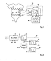
- the figure 1 represents an embodiment of a plethysmograph with inductive turns according to the invention.
- the apparatus is composed of a vest 1 incorporating a thoracic turn 10 and an abdominal turn 20.
- Each of the turns is of variable section and determines the frequency of an associated oscillator, respectively 11 or 21.
- the turns are of variable section thanks to a sinusoidal arrangement in the width of the vest.
- the vest 1 is made of an inextensible fabric in the direction of the height.
- the vest is, as previously indicated, provided with a crotch 2.
- the oscillators 11 and 21 are connected to a processing circuit 30 comprising a frequency-voltage oscillator converter.
- the converter 31 supplies a voltage C representative of the section of the thorax
- the converter 32 supplies a voltage A representative of the section of the abdomen.
- Voltages C, A and their weighted sum S, supplied by an adder 33 can be visualized by any voltage measuring device 40 such as a voltmeter, an oscilloscope, a graphic recorder, etc.
- the summed S can be made representative of the pulmonary volume of the patient by suitably adjusting the weighting coefficients K1 and K2 of the signals A and C.
- the coefficients K1 and K2 are set during a calibration phase. For example, a first step of the calibration phase serves to set these coefficients, and a second step is used to determine a scale for the measured voltage values to correspond to volume units.
- the calibration phase comprises steps of calibrating turns for each posture of the patient (on the back, on the belly, on the right side, on the left side) to obtain a measurement of the breathing using a calibration corresponding to the position provided by a position sensor.
- the vest is also associated with a sensor 15 ( figure 1 ) position of the patient providing information to the treatment circuit 30 for it to adapt the measured results according to the posture of the patient.
- a feature of the present invention is to provide within the operating circuit 30 signals from the oscillators 11 and 21, a particular digital processing of thoracic and abdominal signals.
- This treatment is illustrated in figure 1 by a block 35 receiving the sum of the thoracic tension C and abdominal A.
- figure 1 block 35 also receives the position signal to adapt the system calibration and measurements according to the position of the patient.
- the figure 2 represents, in the form of functional blocks, a preferred embodiment of the present invention.
- This figure illustrates the digital signal processing operated, for example by the block 35 of the figure 1 , on the output signal S of the adder 33.
- the digital signal processing method of the invention starts by digitizing, with respective gains K1 and K2, the voltages A and C of the oscillators 11 and 21 ( figure 1 ).
- This step, followed by a summation, is illustrated by a block 33 in figure 2 .
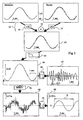
- Curves 61 and 62 of the figure 3 illustrate an example of measured voltages A and C, respectively in the abdomen and thorax using a vest as illustrated by the figure 1 .
- Curve 63 represents the result of the summation 33 of these curves. This curve 63 is therefore representative of the respiratory volume of the patient.
- the volume signal is derived.
- This derivation (block 52, DERIV) is preferably preceded by a filtering step which is chosen to perform a low-pass filter function.
- This step is symbolized by a block 53 which delivers, on an output 54, a signal 64 having substantially the same overall appearance as the curve 63 but on which high frequency disturbances have been eliminated.
- this signal 64 is delivered as being the respiratory volume.
- the cutoff frequency of the low-pass filter is preferably chosen to be between 3 and 20 Hz, and is preferably about 10 Hz.
- the signal 65 is filtered (block 55) to eliminate, in particular, these frequencies greater than Hertz and, preferably, greater than 2/3 of Hertz.
- a band-stop filter is performed in which the frequencies between approximately 2/3 of Hertz and a dozen Hertz are eliminated (preferably between 3 / 4 and 12 Hertz).
- the curves 64, 65 and 66 are referenced with respect to an origin. This indicates that they are calibrated curves.
- a feature of a preferred embodiment of the present invention is to use the respiratory volume signal 64 to determine the patient's heartbeat.
- a band-pass filtering is performed (block 56) whose bandwidth is approximately between 2/3 of Hertz and 4 Hertz.
- the result (exit 57, figure 2 ) band-pass filtering provides a curve 67 whose signal frequency corresponds to the frequency of the patient's heartbeat.
- the bandpass filtering is shown after the filter 53. According to a variant not shown, this filtering is performed directly on the unfiltered volume information (output of the adder 33).
- An advantage of this variant is that it makes the sizing of the filters for obtaining the flow rate and the heart rate independent of each other.
- the heart rate extraction filter is downstream of the low-pass filter 53 which then has a sufficiently low cut-off frequency
- the heart rate is obtained by means of a pass filter. -High whose cutoff frequency is about 3/4 of Hertz.
- the frequency spectrum of the signal can be analyzed. It is known that the heart rate is generally between 3/4 of Hertz and 4 Hertz. It is then considered that the frequency for which the spectrum is maximum in this band is the average heart rate over the analysis period.
- Another method is to detect the period between the successive maxima and minima of the signal 67 taking into account amplitude thresholds below which it is considered that it is noise.
- the median period obtained gives the period of heartbeats.
- An advantage of the present invention is that by measuring only the respiratory volume by means of an inductive turn plethysmograph, at least two different physiological quantities are obtained. More precisely, it is possible to continuously measure, not only the respiratory volume as in conventional systems, but also the respiratory rate, the heart rate, or both. To simplify the presentation, only one respiratory cycle was represented in figure 3 but the measurement is continuous.
- Another advantage is that it minimizes the number of sensors to impose on the patient.
- the present invention even makes it possible to easily isolate another physiological quantity which is the respiratory rate of the patient.
- this respiratory rate is isolated by respiratory volume signal processing by detecting changes in sign relative to an origin placed arbitrarily on the curve 63.
- the flow signal 66 is used to determine the respiratory rate. Indeed, this determination is then much simpler. It suffices to detect the frequency of the rate signal which, by the derivative operation (52), is automatically placed on an origin (zero derivative) corresponding to the slope changes of the volume signal. Thus, it is very easy to isolate the period Tr of the respiratory signal and to deduce the frequency.
- the filters applied to the processed signals perform time-limited limited-domain convolutional filtering.
- each sample k of a signal is replaced by a weighted average g (k) of its neighborhood, encompassing all the samples whose order number is between kp and k + p.
- g represents the weight of the current sample
- g represents the value of the sample.
- the determination of the characteristics of the digital filters respecting the formula above is within the abilities of those skilled in the art from Functional indications provided
- the time taken to calculate the weighted average will be taken into account as a function of the number of coefficients taken for the filter (the range -p to + p), which leads to a delay in the supply of the result, which is a function the sampling frequency and the number of future samples to be taken into account in calculating the weighted average assigned to the current sample.In practice, a number of samples of between 20 and about 60 and other of the current sample gives quite satisfactory results.As the sampling frequency is generally of the order of 30 to 50 Hz, the delay will rarely exceed one second. of, which is perfectly acceptable.
- the implementation of the invention requires the calibration of the system before making a measurement, as is the case for conventional systems.
- Several calibration methods are possible. They all have in common to use a standard device with a mask is placed on the patient's mouth and nose to obtain standard curves. We then try to match as best as possible the curves provided by the plethysmograph during the same respiratory cycles and these standard curves.
- a first calibration step consists of choosing, for example over a cycle, the best combination of the coefficients K1 and K2 so that the pace (without respect of scale) of the sum of the signals corresponds to the pace of a real volume. This amounts to setting the ratio K1 / K2.
- the actual volume is conventionally integrated from a flow measurement. It is known that the choice of a ratio K1 / K2 substantially equal to 2 often provides good results. Therefore, in such a simplified embodiment, a single coefficient must be determined during the calibration phase.
- the coefficients K1 and K2 will be calculated by applying a method called "least squares" as will be seen later.
- the value unit calibration consists in determining the two quantities ⁇ and Z.
- the value Z is generally obtained by averaging the values provided by the analog / digital converter over a range where the signal is zero.
- a pneumotachograph which constitutes a perfectly known device for measuring the respiratory flow rate.
- a characteristic of this first method is that the weighting coefficients are not fixed arbitrarily but optimized by the calibration.
- the scale factor can be obtained in several ways.
- a constant air flow rate is established in a diaphragm type device offering a resistance to pressure.
- This resistance causes a pressure drop between the inlet and the outlet of the diaphragm.
- This pressure drop is measured by the difference of the water levels contained in a U-shaped tube.
- the diaphragm having been previously calibrated by another method, the law is known. which, unlike the water level, matches the flow expressed in usual units (eg liters per second).
- a syringe of known volume is used and the flow curve is converted while this syringe is empty.
- the pneumotachograph is used to measure the patient's breathing rate in parallel with the volume measurement using the plethysmograph.
- the coefficients K1 and K2 are then determined by applying a so-called "least squares" method. This amounts to choosing the coefficients K1 and K2 such that the sum of the squares of the differences between the volume reconstituted by the plethysmograph (K1A + K2C) and the volume provided by the integration of the results of the pneumotachograph, is minimal.
- a second calibration method of the invention it is sought to calibrate the plethysmograph directly from a volume measurement.
- a device for calibrating the respiratory volume must then be used by direct comparison (without integration) compared to a standard volume.
- a conventional syringe of known volume which is connected to the mask of the patient.
- the standard syringe forces a patient inspiratory volume which, to allow calibration, must inspire the entire volume of the standard syringe.
- the amplitude of the inspiratory signal obtained by the plethysmograph then corresponds to the standard volume.
- a syringe is not a preferred embodiment of this second method. Indeed, the inventors consider that the calibration results given by this conventional method are very approximate.
- the use of the standard syringe forces the patient to force his inspirations and expirations. The effort provided by the patient changes his breathing compared to his natural breathing, which is a source of error.
- the invention provides for the use of a particular calibration device of the respiratory volume which overcomes these difficulties.
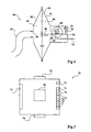
- the figure 4 represents, in a schematic sectional view, a standard device which is not according to the invention.
- This device 80 comprises an airtight enclosure, for example, consisting of two walls 81 and 82 in the form of saucers joined by their respective peripheries.
- the internal volume of the enclosure 80 is divided by a deformable and impervious membrane 83, which defines two chambers 84 and 85.
- a chamber 84 called measurement, comprises a port 86 sealing connection to a measuring tube 87.
- the tube 87 is, for example, intended to be connected to a mask (not shown) applied to the patient's face.
- the other chamber 85 called the standard chamber, has a sensor displacement of the membrane. This sensor is at minimum friction to minimize the risk of disturbance of measurements.
- a rod 88 connected by a first end to the center of the membrane 83, and cooperating with an incremental encoder 89 or a potentiometer.
- the second end of the rod 88 can be connected, by a hinge 90, to a first end of a spring 91 whose other end is fixed, by a hinge 92, to a wall of the chamber 85.
- This embodiment assumes that the elasticity of the membrane is not sufficient to return to the rest position. Otherwise, no reminder is necessary.
- the encoder 89 is contained in the volume of the standard chamber 85. This prevents the rod 88 from crossing a seal which would introduce friction harmful to the measurements.
- the chamber 85 preferably comprises an extension towards the rear of the rod (its second end). Only an electrical connection 93 providing the displacement results converted by the encoder 89 passes through the wall of the chamber 85.
- the encoder 89 includes a toothed wheel 94 to cooperate with teeth 95 that includes the rod 88 in a portion of its length.
- An advantage of the standard device of the invention is that the patient can breathe naturally. Calibration being performed on a small number of breathing cycles, it is not a problem that the patient does not renew his air during calibration.
- the use of the standard device of the invention greatly improves the reliability of a plethysmograph with inductive turns.
- the calibration is particularly simple and comfortable for the patient (in particular, for a patient having breathing difficulties or to which one can not ask to force his breathing, for example, because he is unconscious). It also avoids the use of complex and expensive equipment type pneumotachograph.
- a dedicated interface circuit (the circuit 30, figure 1 ) between the vest 1 with inductive turns and a display or memorizer (40, figure 1 ).
- the figure 5 shows, very schematically and by its inputs-outputs, an embodiment of an interface box 70 according to the present invention.
- This housing 70 includes a microprocessor-based signal processing circuit 30 (e.g., an 8-bit microprocessor).
- the signal inputs essentially comprise an input terminal 71 of the signal coming from the oscillator 11, an input terminal 72 of the signal coming from the oscillator 21 and input terminals 73 associated with the positioning element 15.
- an input terminal 74 for receiving a calibrated flow signal from, for example, a pneumotachograph.
- the interface circuit 70 of the invention serves to organize the exchanges between the different devices, whether during the phases of measurement or during the calibration phases.
- the circuit comprises a serial link (symbolized by its access 75) to a measurement operating device (not shown), for example, a microcomputer.
- the housing 70 needs to be powered and therefore includes one or more contacts 76 to a power supply (not shown).
- the interface circuit 70 of the invention comprises all the necessary elements. However, it may be desirable to have measured analog quantities for display on conventional displays intended to receive this type of data. Therefore, in a preferred embodiment, a digital-to-analog conversion of the measurements and determinations performed is provided. These different measurements are reproduced on a terminal block 77 delivering analog signals. It will be, for example, analogous trends of the tensions of the inductive coil of the thorax, the inductive coil of the abdomen, the volume signal (54, figure 2 ), the position signal, the flow rate (58, figure 2 ), heart rate (signal 57, figure 2 ), respiratory rate, etc.
- the present invention is susceptible of various variations and modifications which will be apparent to those skilled in the art.
- the practical realization of the circuits necessary for carrying out the method of the invention is within the abilities of those skilled in the art from the functional indications given above.
- the grouping of different functions within the same interface box is deduced from the foregoing and known techniques.
- the practical realization of the digital filters used is within the abilities of those skilled in the art based on the functional indications given in the present description.
- reference has been made to preferred calibration methods other conventional methods may be used to calibrate a system of the invention.
- the inductive wound plethysmograph is integrated in a vest worn by the patient, the method of treatment of signals of the invention may more generally be implemented with an inductive turns plethysmograph having separate strips.
Landscapes
- Health & Medical Sciences (AREA)
- Life Sciences & Earth Sciences (AREA)
- Heart & Thoracic Surgery (AREA)
- Surgery (AREA)
- Physics & Mathematics (AREA)
- Dentistry (AREA)
- Biophysics (AREA)
- Pathology (AREA)
- Engineering & Computer Science (AREA)
- Biomedical Technology (AREA)
- Physiology (AREA)
- Medical Informatics (AREA)
- Molecular Biology (AREA)
- Oral & Maxillofacial Surgery (AREA)
- Animal Behavior & Ethology (AREA)
- General Health & Medical Sciences (AREA)
- Public Health (AREA)
- Veterinary Medicine (AREA)
- Measurement Of The Respiration, Hearing Ability, Form, And Blood Characteristics Of Living Organisms (AREA)
- Measuring Pulse, Heart Rate, Blood Pressure Or Blood Flow (AREA)
- Measuring And Recording Apparatus For Diagnosis (AREA)
- Investigating Or Analysing Biological Materials (AREA)
- Collating Specific Patterns (AREA)
Claims (8)
- Verfahren zum Überwachen physiologischer Daten mittels eines Plethysmographen mit thorakalen (10) und abdominellen (20) Induktionsspulen, welches folgende Schritte aufweist:Messen (31, 32) der Atmungsamplituden (61, 62) eines Patienten;Aufsummieren (33) dieser Atmungsamplituden, denen ein entsprechender Gewichtungskoeffizient (K1, K2) zugeordnet ist, um ein Signal (63) zu erhalten, welches für das Atmungsvolumen repräsentativ ist;Durchführen einer Filterung (56) des Signals; undErhalten der Herzfrequenz (67) des Patienten aus dem gefilterten Signal.
- Verfahren nach Anspruch 1, dadurch gekennzeichnet, dass es sich um eine Filterung vom Bandpass-Typ mit einem Durchlassbereich zwischen 2/3 Hertz und 4 Hertz handelt.
- Verfahren nach einem der Ansprüche 1 oder 2, wobei eine Tiefpassfilterung (53) mit einer Grenzfrequenz kleiner als 20 Hertz, und vorzugsweise in der Größenordnung von 10 Hertz, des Signals (63), welches für das Atmungsvolumen repräsentativ ist, vor der Bandpassfilterung durchgeführt wird.
- Verfahren nach Anspruch 3, welches ferner folgende Schritte aufweist:Ableiten (52) des Signals, welches aus der Tiefpassfilterung resultiert; undAnwenden einer Filterung (55) vom Bandsperrtyp mit Grenzfrequenzen von ungefähr 2/3 Hertz und 12 Hertz auf das Resultat des vorherigen Filterschrittes, um den Atemfluss (66) des Patienten zu erhalten.
- Vorrichtung zum Überwachen physiologischer Daten mittels eines Plethysmographen mit thorakalen (10) und abdominellen (20) Induktionsspulen, welche Folgendes aufweist:Mittel (31, 32) zum Messen der Atemamplituden (61, 62) eines Patienten;Mittel (31, 32) zum Zuweisen eines entsprechenden Gewichtungskoeffizienten (K1, K2) an die gemessenen Atmungsamplituden;Mittel (33) zum Aufsummieren dieser Atmungsamplituden, denen ihr entsprechender Gewichtungskoeffizient zugewiesen ist, wobei diese Mittel ein Signal (63) liefern, welches für das Atmungsvolumen repräsentativ ist;Mittel zu einer digitalen Verarbeitung des Signals; undMittel zum Erhalten der Herzfrequenz des Patienten aus Filtermitteln, die in den digitalen Verarbeitungsmitteln enthalten sind.
- Vorrichtung nach Anspruch 5, wobei es sich um Filtermittel vom Band-pass-Typ mit einem Durchlassbereich zwischen 2/3 Hertz und 4 Hertz handelt.
- Vorrichtung nach Anspruch 5, dadurch gekennzeichnet, dass die Induktionsspulen in einer Textiljacke (1) mit Maschen integriert sind, die in der Höhe nicht dehnbaren sind.
- Vorrichtung nach Anspruch 5 oder 6, dadurch gekennzeichnet, dass sie ferner einen Sensor (15) für die Position des Patienten aufweist.
Applications Claiming Priority (3)
| Application Number | Priority Date | Filing Date | Title |
|---|---|---|---|
| FR0008743A FR2811214B1 (fr) | 2000-07-05 | 2000-07-05 | Procede et dispositif de determination de parametres physiologiques cardio-respiratoires |
| FR0008743 | 2000-07-05 | ||
| PCT/FR2001/002160 WO2002002013A1 (fr) | 2000-07-05 | 2001-07-05 | Procede et dispositif de determination de parametres physiologiques cardio-respiratoires |
Publications (2)
| Publication Number | Publication Date |
|---|---|
| EP1296594A1 EP1296594A1 (de) | 2003-04-02 |
| EP1296594B1 true EP1296594B1 (de) | 2011-03-02 |
Family
ID=8852133
Family Applications (1)
| Application Number | Title | Priority Date | Filing Date |
|---|---|---|---|
| EP01984090A Expired - Lifetime EP1296594B1 (de) | 2000-07-05 | 2001-07-05 | Verfahren und vorrichtung zum bestimmen von physiologischen herz-atemparametern |
Country Status (7)
| Country | Link |
|---|---|
| EP (1) | EP1296594B1 (de) |
| JP (1) | JP2004501713A (de) |
| AT (1) | ATE499875T1 (de) |
| DE (1) | DE60144148D1 (de) |
| ES (1) | ES2357810T3 (de) |
| FR (1) | FR2811214B1 (de) |
| WO (1) | WO2002002013A1 (de) |
Families Citing this family (12)
| Publication number | Priority date | Publication date | Assignee | Title |
|---|---|---|---|---|
| FR2940038A1 (fr) * | 2008-12-22 | 2010-06-25 | Rbi | Procede et systeme de surveillance de la deglutition |
| WO2010131267A1 (en) | 2009-05-15 | 2010-11-18 | Nox Medical | System and methods using flexible capacitive electrodes for measuring biosignals |
| WO2011024153A1 (en) * | 2009-08-31 | 2011-03-03 | Koninklijke Philips Electronics N.V. | Method and system for detecting respiratory information |
| EP2584962B1 (de) | 2010-06-25 | 2014-09-10 | Nox Medical ehf. | Biometrischer bandverbinder |
| JP6140562B2 (ja) * | 2013-07-24 | 2017-05-31 | 株式会社槌屋 | 呼吸測定方法および呼吸測定装置 |
| EP3065638B1 (de) | 2013-11-06 | 2024-01-10 | Nox Medical ehf. | Verfahren, vorrichtung und system zur messung einer atemanstrengung |
| KR102348629B1 (ko) * | 2013-11-28 | 2022-01-07 | 웨스턴 시드니 유니버시티 | 폐심장 기능 관찰 |
| US20180333102A1 (en) * | 2015-12-01 | 2018-11-22 | Koninklijke Philips N.V. | Device, system and method for determining vital sign information of a subject |
| WO2018033889A1 (en) | 2016-08-19 | 2018-02-22 | Nox Medical | Method, apparatus, and system for measuring respiratory effort of a subject |
| WO2018220606A1 (en) | 2017-06-02 | 2018-12-06 | Nox Medical Ehf | Coherence-based method, apparatus, and system for identifying corresponding signals of a physiological study |
| EP3678543A1 (de) | 2017-09-08 | 2020-07-15 | Nox Medical | System und verfahren zur nichtinvasiven bestimmung einer internen komponente der respiratorischen belastung |
| CN114191788B (zh) * | 2020-09-02 | 2022-09-23 | 中国人民解放军总医院 | 个体化的呼吸运动模式重建训练系统及其使用方法 |
Citations (1)
| Publication number | Priority date | Publication date | Assignee | Title |
|---|---|---|---|---|
| GB1596298A (en) * | 1977-04-07 | 1981-08-26 | Morgan Ltd P K | Method of and apparatus for detecting or measuring changes in the cross-sectional area of a non-magnetic object |
Family Cites Families (6)
| Publication number | Priority date | Publication date | Assignee | Title |
|---|---|---|---|---|
| FR2286370A1 (fr) * | 1974-09-24 | 1976-04-23 | Adam Georges | Perfectionnements aux procedes et dispositifs pour la mesure du volume d'un gaz sous pression |
| NL8500314A (nl) | 1984-07-19 | 1986-02-17 | Drs Erna Peltzer | Inrichting voor het bepalen van het ademhalingsgedrag van een patient. |
| US4784162A (en) | 1986-09-23 | 1988-11-15 | Advanced Medical Technologies | Portable, multi-channel, physiological data monitoring system |
| FR2664487B1 (fr) * | 1990-07-16 | 1995-03-03 | Univ Angers | Systeme pour l'analyse de parametres de la respiration pendant le sommeil. |
| DE69839008D1 (de) * | 1997-03-17 | 2008-03-06 | Vivometrics Inc | F ihren einfluss auf neuromuskuläre atmung |
| FR2787008B1 (fr) | 1998-12-09 | 2001-04-13 | R B I | Dispositif de mesure de respiration |
-
2000
- 2000-07-05 FR FR0008743A patent/FR2811214B1/fr not_active Expired - Fee Related
-
2001
- 2001-07-05 DE DE60144148T patent/DE60144148D1/de not_active Expired - Lifetime
- 2001-07-05 EP EP01984090A patent/EP1296594B1/de not_active Expired - Lifetime
- 2001-07-05 WO PCT/FR2001/002160 patent/WO2002002013A1/fr not_active Ceased
- 2001-07-05 JP JP2002506643A patent/JP2004501713A/ja active Pending
- 2001-07-05 AT AT01984090T patent/ATE499875T1/de not_active IP Right Cessation
- 2001-07-05 ES ES01984090T patent/ES2357810T3/es not_active Expired - Lifetime
Patent Citations (1)
| Publication number | Priority date | Publication date | Assignee | Title |
|---|---|---|---|---|
| GB1596298A (en) * | 1977-04-07 | 1981-08-26 | Morgan Ltd P K | Method of and apparatus for detecting or measuring changes in the cross-sectional area of a non-magnetic object |
Also Published As
| Publication number | Publication date |
|---|---|
| EP1296594A1 (de) | 2003-04-02 |
| WO2002002013A1 (fr) | 2002-01-10 |
| JP2004501713A (ja) | 2004-01-22 |
| ES2357810T3 (es) | 2011-04-29 |
| DE60144148D1 (de) | 2011-04-14 |
| ATE499875T1 (de) | 2011-03-15 |
| FR2811214B1 (fr) | 2003-01-31 |
| FR2811214A1 (fr) | 2002-01-11 |
Similar Documents
| Publication | Publication Date | Title |
|---|---|---|
| CN107920766B (zh) | 睡眠现象监测 | |
| JP6669409B2 (ja) | 血圧値を測定するための方法、機器及びコンピュータプログラム | |
| EP3110321B1 (de) | Verfahren, vorrichtung, system und computerprogramm zur filterung einer aus einem herzsignal abgeleiteten rr-serie mit automatischer qualitätskontrolle der rr-serie | |
| CN105769122B (zh) | 一种睡眠呼吸暂停低通气指数的测量设备 | |
| EP1296594A1 (de) | Verfahren und vorrichtung zum bestimmen von physiologischen herz-atemparametern | |
| JP2018517528A5 (de) | ||
| EP1006863A1 (de) | Verfahren und gerät zur adaptiven mittelwertbildung von datensignalen | |
| EP0527216A1 (de) | Vorrichtung zur diagnostik. | |
| WO2003101291A1 (fr) | Traitement frequentiel d'une serie rr dans un signal cardiaque analogique | |
| Ruangsuwana et al. | Methods to extract respiration information from ECG signals | |
| Młyńczak et al. | Decomposition of the cardiac and respiratory components from impedance pneumography signals | |
| EP1804655B1 (de) | System und programm zur verarbeitung einer reihe von herzrhythmussignalen (rr) zur beurteilung von schmerz oder stress eines patienten | |
| JP7133576B2 (ja) | 位相差法による連続血圧測定システム | |
| EP1424037B1 (de) | Vorrichtung für die nicht-invasive Messung des arteriellen Blutdrucks, insbesonders für die ambulante Überwachung des arteriellen Blutdrucks | |
| EP3110322B1 (de) | Verfahren und vorrichtung zur automatischen überprüfung der qualität einer aus einem herzsignal ermittelten rr-intervallserie | |
| Dovancescu et al. | Detection of electrocardiographic and respiratory signals from transthoracic bioimpedance spectroscopy measurements with a wearable monitor for improved home-based disease management in congestive heart failure | |
| EP2184011A1 (de) | Medizinische Vorrichtung vom Typ implantierbare Herzprothese, die spirometrische Mittel zur Diagnose von Lungenerkrankungen beinhaltet | |
| EP0681448A1 (de) | Verfahren und vorrichtung zum kontinuierlichen messen des blutdrucks | |
| FR2787008A1 (fr) | Dispositif de mesure de respiration | |
| FR3100705A1 (fr) | Procédé de détermination du taux respiratoire | |
| CN118490196A (zh) | 一种基于心冲击信号图的逐拍心率计算方法和系统 | |
| CN121015159A (zh) | 血压测量方法、装置、计算机设备及存储介质 | |
| EP0221981A1 (de) | Vorrichtung zum automatischen messen des blutdrucks | |
| CN119423735A (zh) | 呼吸信号可靠性判断方法、装置和存储介质 | |
| FR3151970A1 (fr) | Procede et dispositif de calcul d’au moins un indice de variabilite de la frequence cardiaque a partir d’une serie rr |
Legal Events
| Date | Code | Title | Description |
|---|---|---|---|
| PUAI | Public reference made under article 153(3) epc to a published international application that has entered the european phase |
Free format text: ORIGINAL CODE: 0009012 |
|
| 17P | Request for examination filed |
Effective date: 20030130 |
|
| AK | Designated contracting states |
Kind code of ref document: A1 Designated state(s): AT BE CH CY DE DK ES FI FR GB GR IE IT LI LU MC NL PT SE TR |
|
| 17Q | First examination report despatched |
Effective date: 20081219 |
|
| GRAP | Despatch of communication of intention to grant a patent |
Free format text: ORIGINAL CODE: EPIDOSNIGR1 |
|
| GRAS | Grant fee paid |
Free format text: ORIGINAL CODE: EPIDOSNIGR3 |
|
| GRAA | (expected) grant |
Free format text: ORIGINAL CODE: 0009210 |
|
| AK | Designated contracting states |
Kind code of ref document: B1 Designated state(s): AT BE CH CY DE DK ES FI FR GB GR IE IT LI LU MC NL PT SE TR |
|
| REG | Reference to a national code |
Ref country code: GB Ref legal event code: FG4D Free format text: NOT ENGLISH |
|
| REG | Reference to a national code |
Ref country code: CH Ref legal event code: EP |
|
| REG | Reference to a national code |
Ref country code: IE Ref legal event code: FG4D Free format text: LANGUAGE OF EP DOCUMENT: FRENCH |
|
| REF | Corresponds to: |
Ref document number: 60144148 Country of ref document: DE Date of ref document: 20110414 Kind code of ref document: P |
|
| REG | Reference to a national code |
Ref country code: DE Ref legal event code: R096 Ref document number: 60144148 Country of ref document: DE Effective date: 20110414 |
|
| REG | Reference to a national code |
Ref country code: ES Ref legal event code: FG2A Ref document number: 2357810 Country of ref document: ES Kind code of ref document: T3 Effective date: 20110429 |
|
| REG | Reference to a national code |
Ref country code: NL Ref legal event code: VDEP Effective date: 20110302 |
|
| PG25 | Lapsed in a contracting state [announced via postgrant information from national office to epo] |
Ref country code: GR Free format text: LAPSE BECAUSE OF FAILURE TO SUBMIT A TRANSLATION OF THE DESCRIPTION OR TO PAY THE FEE WITHIN THE PRESCRIBED TIME-LIMIT Effective date: 20110603 Ref country code: SE Free format text: LAPSE BECAUSE OF FAILURE TO SUBMIT A TRANSLATION OF THE DESCRIPTION OR TO PAY THE FEE WITHIN THE PRESCRIBED TIME-LIMIT Effective date: 20110302 |
|
| PG25 | Lapsed in a contracting state [announced via postgrant information from national office to epo] |
Ref country code: NL Free format text: LAPSE BECAUSE OF FAILURE TO SUBMIT A TRANSLATION OF THE DESCRIPTION OR TO PAY THE FEE WITHIN THE PRESCRIBED TIME-LIMIT Effective date: 20110302 Ref country code: FI Free format text: LAPSE BECAUSE OF FAILURE TO SUBMIT A TRANSLATION OF THE DESCRIPTION OR TO PAY THE FEE WITHIN THE PRESCRIBED TIME-LIMIT Effective date: 20110302 Ref country code: AT Free format text: LAPSE BECAUSE OF FAILURE TO SUBMIT A TRANSLATION OF THE DESCRIPTION OR TO PAY THE FEE WITHIN THE PRESCRIBED TIME-LIMIT Effective date: 20110302 Ref country code: CY Free format text: LAPSE BECAUSE OF FAILURE TO SUBMIT A TRANSLATION OF THE DESCRIPTION OR TO PAY THE FEE WITHIN THE PRESCRIBED TIME-LIMIT Effective date: 20110302 |
|
| PGFP | Annual fee paid to national office [announced via postgrant information from national office to epo] |
Ref country code: GB Payment date: 20110627 Year of fee payment: 11 |
|
| REG | Reference to a national code |
Ref country code: IE Ref legal event code: FD4D |
|
| PG25 | Lapsed in a contracting state [announced via postgrant information from national office to epo] |
Ref country code: PT Free format text: LAPSE BECAUSE OF FAILURE TO SUBMIT A TRANSLATION OF THE DESCRIPTION OR TO PAY THE FEE WITHIN THE PRESCRIBED TIME-LIMIT Effective date: 20110704 Ref country code: IE Free format text: LAPSE BECAUSE OF FAILURE TO SUBMIT A TRANSLATION OF THE DESCRIPTION OR TO PAY THE FEE WITHIN THE PRESCRIBED TIME-LIMIT Effective date: 20110302 |
|
| PGFP | Annual fee paid to national office [announced via postgrant information from national office to epo] |
Ref country code: FR Payment date: 20110811 Year of fee payment: 11 Ref country code: DE Payment date: 20110713 Year of fee payment: 11 Ref country code: ES Payment date: 20110829 Year of fee payment: 11 |
|
| PGFP | Annual fee paid to national office [announced via postgrant information from national office to epo] |
Ref country code: IT Payment date: 20110721 Year of fee payment: 11 Ref country code: BE Payment date: 20110727 Year of fee payment: 11 |
|
| PLBE | No opposition filed within time limit |
Free format text: ORIGINAL CODE: 0009261 |
|
| STAA | Information on the status of an ep patent application or granted ep patent |
Free format text: STATUS: NO OPPOSITION FILED WITHIN TIME LIMIT |
|
| 26N | No opposition filed |
Effective date: 20111205 |
|
| PG25 | Lapsed in a contracting state [announced via postgrant information from national office to epo] |
Ref country code: DK Free format text: LAPSE BECAUSE OF FAILURE TO SUBMIT A TRANSLATION OF THE DESCRIPTION OR TO PAY THE FEE WITHIN THE PRESCRIBED TIME-LIMIT Effective date: 20110302 Ref country code: MC Free format text: LAPSE BECAUSE OF NON-PAYMENT OF DUE FEES Effective date: 20110731 |
|
| REG | Reference to a national code |
Ref country code: CH Ref legal event code: PL |
|
| REG | Reference to a national code |
Ref country code: DE Ref legal event code: R097 Ref document number: 60144148 Country of ref document: DE Effective date: 20111205 |
|
| PG25 | Lapsed in a contracting state [announced via postgrant information from national office to epo] |
Ref country code: LI Free format text: LAPSE BECAUSE OF NON-PAYMENT OF DUE FEES Effective date: 20110731 Ref country code: CH Free format text: LAPSE BECAUSE OF NON-PAYMENT OF DUE FEES Effective date: 20110731 |
|
| BERE | Be: lapsed |
Owner name: R.B.I. Effective date: 20120731 |
|
| GBPC | Gb: european patent ceased through non-payment of renewal fee |
Effective date: 20120705 |
|
| REG | Reference to a national code |
Ref country code: FR Ref legal event code: ST Effective date: 20130329 |
|
| PG25 | Lapsed in a contracting state [announced via postgrant information from national office to epo] |
Ref country code: FR Free format text: LAPSE BECAUSE OF NON-PAYMENT OF DUE FEES Effective date: 20120731 Ref country code: GB Free format text: LAPSE BECAUSE OF NON-PAYMENT OF DUE FEES Effective date: 20120705 Ref country code: DE Free format text: LAPSE BECAUSE OF NON-PAYMENT OF DUE FEES Effective date: 20130201 |
|
| REG | Reference to a national code |
Ref country code: DE Ref legal event code: R119 Ref document number: 60144148 Country of ref document: DE Effective date: 20130201 |
|
| PG25 | Lapsed in a contracting state [announced via postgrant information from national office to epo] |
Ref country code: LU Free format text: LAPSE BECAUSE OF NON-PAYMENT OF DUE FEES Effective date: 20110705 Ref country code: BE Free format text: LAPSE BECAUSE OF NON-PAYMENT OF DUE FEES Effective date: 20120731 Ref country code: IT Free format text: LAPSE BECAUSE OF NON-PAYMENT OF DUE FEES Effective date: 20120705 |
|
| PG25 | Lapsed in a contracting state [announced via postgrant information from national office to epo] |
Ref country code: TR Free format text: LAPSE BECAUSE OF FAILURE TO SUBMIT A TRANSLATION OF THE DESCRIPTION OR TO PAY THE FEE WITHIN THE PRESCRIBED TIME-LIMIT Effective date: 20110302 |
|
| REG | Reference to a national code |
Ref country code: ES Ref legal event code: FD2A Effective date: 20131021 |
|
| PG25 | Lapsed in a contracting state [announced via postgrant information from national office to epo] |
Ref country code: ES Free format text: LAPSE BECAUSE OF NON-PAYMENT OF DUE FEES Effective date: 20120706 |