EP1296071A2 - Einschnappbare Anordnung aus einem Schraubverbindungselement und einer Scheibe mit Stift - Google Patents
Einschnappbare Anordnung aus einem Schraubverbindungselement und einer Scheibe mit Stift Download PDFInfo
- Publication number
- EP1296071A2 EP1296071A2 EP02020988A EP02020988A EP1296071A2 EP 1296071 A2 EP1296071 A2 EP 1296071A2 EP 02020988 A EP02020988 A EP 02020988A EP 02020988 A EP02020988 A EP 02020988A EP 1296071 A2 EP1296071 A2 EP 1296071A2
- Authority
- EP
- European Patent Office
- Prior art keywords
- threaded fastener
- washer
- fastener
- assembly
- standoff
- Prior art date
- Legal status (The legal status is an assumption and is not a legal conclusion. Google has not performed a legal analysis and makes no representation as to the accuracy of the status listed.)
- Granted
Links
- 230000002093 peripheral effect Effects 0.000 claims description 4
- 230000013011 mating Effects 0.000 abstract description 28
- 238000000034 method Methods 0.000 abstract description 12
- 230000000717 retained effect Effects 0.000 abstract description 3
- 239000000463 material Substances 0.000 description 9
- 238000009987 spinning Methods 0.000 description 4
- 229920001971 elastomer Polymers 0.000 description 3
- 238000003780 insertion Methods 0.000 description 3
- 230000037431 insertion Effects 0.000 description 3
- 230000033001 locomotion Effects 0.000 description 3
- 238000004519 manufacturing process Methods 0.000 description 3
- 239000002184 metal Substances 0.000 description 3
- 229910052751 metal Inorganic materials 0.000 description 3
- 239000004033 plastic Substances 0.000 description 3
- 229920003023 plastic Polymers 0.000 description 3
- 239000005060 rubber Substances 0.000 description 3
- 230000008901 benefit Effects 0.000 description 2
- 230000008878 coupling Effects 0.000 description 2
- 238000010168 coupling process Methods 0.000 description 2
- 238000005859 coupling reaction Methods 0.000 description 2
- 238000002788 crimping Methods 0.000 description 2
- 150000002739 metals Chemical class 0.000 description 2
- 238000012986 modification Methods 0.000 description 2
- 230000004048 modification Effects 0.000 description 2
- 230000000750 progressive effect Effects 0.000 description 2
- 230000006835 compression Effects 0.000 description 1
- 238000007906 compression Methods 0.000 description 1
- 239000006260 foam Substances 0.000 description 1
- 239000006261 foam material Substances 0.000 description 1
- 239000011521 glass Substances 0.000 description 1
- 210000003141 lower extremity Anatomy 0.000 description 1
- 230000007246 mechanism Effects 0.000 description 1
- 230000035515 penetration Effects 0.000 description 1
- 230000008569 process Effects 0.000 description 1
Images

Classifications
-
- F—MECHANICAL ENGINEERING; LIGHTING; HEATING; WEAPONS; BLASTING
- F16—ENGINEERING ELEMENTS AND UNITS; GENERAL MEASURES FOR PRODUCING AND MAINTAINING EFFECTIVE FUNCTIONING OF MACHINES OR INSTALLATIONS; THERMAL INSULATION IN GENERAL
- F16B—DEVICES FOR FASTENING OR SECURING CONSTRUCTIONAL ELEMENTS OR MACHINE PARTS TOGETHER, e.g. NAILS, BOLTS, CIRCLIPS, CLAMPS, CLIPS OR WEDGES; JOINTS OR JOINTING
- F16B5/00—Joining sheets or plates, e.g. panels, to one another or to strips or bars parallel to them
- F16B5/02—Joining sheets or plates, e.g. panels, to one another or to strips or bars parallel to them by means of fastening members using screw-thread
-
- F—MECHANICAL ENGINEERING; LIGHTING; HEATING; WEAPONS; BLASTING
- F16—ENGINEERING ELEMENTS AND UNITS; GENERAL MEASURES FOR PRODUCING AND MAINTAINING EFFECTIVE FUNCTIONING OF MACHINES OR INSTALLATIONS; THERMAL INSULATION IN GENERAL
- F16B—DEVICES FOR FASTENING OR SECURING CONSTRUCTIONAL ELEMENTS OR MACHINE PARTS TOGETHER, e.g. NAILS, BOLTS, CIRCLIPS, CLAMPS, CLIPS OR WEDGES; JOINTS OR JOINTING
- F16B43/00—Washers or equivalent devices; Other devices for supporting bolt-heads or nuts
-
- Y—GENERAL TAGGING OF NEW TECHNOLOGICAL DEVELOPMENTS; GENERAL TAGGING OF CROSS-SECTIONAL TECHNOLOGIES SPANNING OVER SEVERAL SECTIONS OF THE IPC; TECHNICAL SUBJECTS COVERED BY FORMER USPC CROSS-REFERENCE ART COLLECTIONS [XRACs] AND DIGESTS
- Y10—TECHNICAL SUBJECTS COVERED BY FORMER USPC
- Y10S—TECHNICAL SUBJECTS COVERED BY FORMER USPC CROSS-REFERENCE ART COLLECTIONS [XRACs] AND DIGESTS
- Y10S411/00—Expanded, threaded, driven, headed, tool-deformed, or locked-threaded fastener
- Y10S411/999—Expanded, threaded, driven, headed, tool-deformed, or locked-threaded fastener with retainer, e.g. tether
Definitions
- the present technique relates generally to the field of fasteners and, more particularly, to a fastener joined in an assembly with a stemmed washer.
- the present technique also relates to a system and method for retaining a fastener and such an assembly.
- a variety of applications are known for threaded fasteners used with standoffs.
- a standoff is commonly inserted into an aperture in the compressible material, and threaded or other fasteners are placed through the standoff for securing the compressible material in a desired position.
- Compressible materials on which standoffs are commonly used include various plastics, rubbers, foam materials, and so forth, but may also include expanded metals, cellulosic products, and so forth.
- standoffs are also commonly used in applications wherein penetration of one or more fasteners is to be limited, although the material being fastened in place is not necessarily particularly compressible, such as in fragile or brittle materials.
- stemmed washer and fastener assembly which has a fastener captured by a stemmed washer.
- a technique is also needed for mounting the stemmed washer in assembly with one or more structures or panels.
- the present technique provides a stemmed washer and fastener assembly, which has a fastener retained in assembly with a stemmed washer.
- the assembly is particularly useful for applications in which a standoff is desired between a washer and a mating fastener.
- the stemmed washer includes a washer portion, a retaining portion, and a standoff portion.
- the retaining portion interfaces with the fastener, such as with a plastically deformed skirt portion, to retain the fastener in the assembly.
- the standoff portion has a toolfree mounting structure, such as a snap-fit member, to mount the stemmed washer and fastener assembly to one or more panels, thereby forming a fastener-panel assembly.
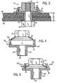
- Figure 1 is a perspective view of a fastener and stemmed washer assembly in accordance with certain aspects of the present technique
- Figure 2 is a sectional view through the assembly of Figure 1 illustrating an exemplary configuration of the internally threaded fastener and stemmed washer;
- Figure 3 is a sectional view of the assembly illustrated in Figures 1 and 2, installed with a mating fastener to maintain elements in the desired location within a final assembly;
- Figures 4 and 5 are sectional views of the assembly of Figures 1 and 2 showing steps in progressive manufacture of the assembly for retaining the threaded fastener within the stemmed washer;
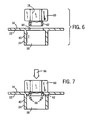
- Figures 6 and 7 illustrate in partial section an alternative configuration of a threaded fastener secured to a stemmed washer in accordance with aspects of the present technique
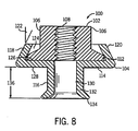
- Figure 8 is a cross-sectional side view of an alternative stemmed washer and fastener assembly having a toolfree mounting structure
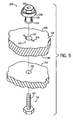
- Figure 9 is a perspective view illustrating the stemmed washer and fastener assembly exploded from a plurality of panels and a mating fastener
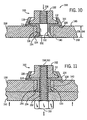
- Figure 10 is a cross-sectional side view illustrating the stemmed washer and fastener assembly removably mounted to a panel via the toolfree mounting structure;
- Figure 11 is a cross-sectional side view illustrating the stemmed washer and fastener assembly assembled with the plurality of panels and the mating fastener illustrated in Figure 9.
- the assembly includes an internally threaded fastener 12 secured to a stemmed washer 14.
- the fastener 12 is a hex nut having hex flats 16 for interfacing with a conventional wrench.
- Internal threads 18 are provided for interfacing with a mating threaded fastener as described in greater detail below.
- a peripheral flange 20 is formed around a base of fastener 12 to interface with a corresponding portion of the stemmed washer to maintain the fastener in the assembly and to permit free spinning of the fastener for securement in an application.
- the stemmed washer 14 includes features which serve both as a conventional washer, as a standoff, and as a retaining structure for the fastener 12.
- the stemmed washer 14 thus includes a generally planar washer portion 22 integrally formed with a standoff portion 24.
- Standoff portion 24 is generally right cylindrical in shape in the illustrated embodiment, although other overall shapes (e.g., tapered) may be employed.
- the shape and contour of the washer portion 22 may be adapted for various purposes, and may deviate from the planar shape illustrated.
- the retaining portion 26 extends upwardly from the washer portion 22 and extends inwardly slightly over the flange 20 of the fastener to retain the fastener within the assembly. In a present embodiment, the retaining portion 26 fits loosely around the flange 26 to permit free spinning movement of the fastener within the assembly.
- the assembly of Figure 1 is illustrated in cross-section.
- the assembly 10 includes a fastener 12 and a stemmed washer 14.
- the stemmed washer includes a washer portion 22, a lower standoff portion 24, and a retaining portion 26.
- the retaining portion 26 generally forms an upstanding skirt 28 bent inwardly towards the fastener 12 so as to retain the fastener by interference with the flange 20 provided at the lower extremity of the fastener. While the upstanding skirt 28 may have any suitable shape and contour, in the illustrated embodiment the skirt is angled inwardly slightly through an angle 30 to form a cavity 32 in which the fastener is retained.
- the fastener thus rests upon a base 34 of the cavity 32 and exerts force against the base when drawn into engagement with a mating fastener.
- the washer portion 22 presents an abutment surface 36 at its lower face opposite the base 34 for contacting an element to be secured in place.
- the standoff portion 34 has an aperture 38 extending therethrough for receiving a mating fastener as described below.
- Aperture 38 is surrounded by side walls 40, which as noted above, may be straight cylindrical in shape as illustrated, or may be contoured, flared, or otherwise bent or ridged.
- a lower abutment end 42 of the standoff portion 24 serves to contact a mating surface, such as of a mating fastener as described below.
- the standoff portion 24 may be provided, as illustrated at reference numeral 44 in Figure 2.
- the dimension 44 extends between the abutment surface 36 and the abutment end 42, thereby defining a final dimension between which elements to be secured in place are disposed.
- the length of dimensions 44 will generally correspond to a desired distance between an upper location of an element to be secured in place, and a lower location of a mating component, such as a fastener.
- FIG. 3 The assembly of Figures 1 and 2 is illustrated in an application in Figure 3.
- the assembly 10 is designed to cooperate with a mating fastener 46, such as a screw or bolt, which is received within the internally threaded fastener 12 of the assembly.
- a mating fastener 46 such as a screw or bolt
- the assembly 10 may be simply inserted into apertures formed within elements to be secured to one another, such as element 48 and element 50 in the illustrated embodiment of Figure 3, and the mating fastener 46 inserted from an opposite side.
- the fastener 46, and/or the fastener 12 may then be rotated to join the assembly 10 to the fastener 46, with the elements 48 and 50 lodged therebetween.
- the fastener 12 is free to rotate within assembly 10 as described above.
- the fastener may be fixed with respect to the retaining stemmed washer, such that only fastener 46 is rotated for securement.
- the final assembly presents a spacing or dimension 52 between the abutment surface 36 and abutment end 42 of the stemmed washer 14.
- the dimension 52 will be equivalent to dimension 44 illustrated in Figure 2.
- the final dimension may provide for loose attachment of the elements to one another, or slight crushing or compression of one or both elements.
- the arrangement is thus particularly well suited to fastening components which may be damaged or deformed in use, such as plastics, rubbers, expanded metals, and so forth.
- the arrangement is also particularly well suited to fastening components for which dimensions should be maintained or over-pressure should be avoided, such as metal, glass, and other harder and dimensionally stable components.
- Figures 4 and 5 illustrate progressive manufacturing assembly of the elements described above.
- the stemmed washer 14 is formed, such as by a drawing or stamping operation, to form a blank 54.
- the blank 54 presents the standoff portion 24 and integral washer portion 22, with the washer portion 22 presenting a generally upstanding open skirt 54 defining cavity 32.
- the internally threaded fastener 12 is then placed within the cavity 32 as illustrated in Figure 4. With the fastener thus in place, the open skirt 56 of Figure 4 is bent inwardly, such as in a crimping operation, as illustrated by arrows 58 in Figure 5.
- this operation may secure the fastener rigidly within the assembly to prevent rotation, in a presently preferred configuration, the fastener 12 may freely spin within the cavity 32 to allow securement to a mating fastener, while the stemmed washer remains stationary.
- Figures 6 and 7 illustrate an alternative configuration of an internally threaded fastener secured to a stemmed washer.
- an alternative threaded fastener 60 includes internal thread 18 as in the previous embodiments, but further includes a lower skirt or extension 62.
- Skirt 62 may be formed by any suitable process, such as during the initial fabrication of the fastener.
- Extension 62 forms a generally cylindrical skirt extending downwardly from the threaded fastener.
- the skirt may be continuous, extending in an uninterrupted cylinder around the base of the fastener, or may be discontinuous, forming tabs or individual extension feet around the fastener.
- the stemmed washer 14 in this embodiment includes a radially-projecting internal ridge 64 designed and dimensioned to receive the skirt 62 of the fastener.
- the internally threaded fastener 60 is lowered into the aperture formed by the ridge 64, as illustrated by arrow 66.
- the skirt is then deformed plastically, such as through a crimping or flaring operation, to secure the skirt within the stemmed washer.
- skirt 62 is deformed so as to provide for free rotation of the fastener within the stemmed washer.
- the deforming operation performed on the skirt may be such as to fixedly secure the nut with relation to the stemmed washer to prevent their mutual rotation.
- Figures 8-11 illustrate an alternative stemmed washer and fastener assembly 100, which is configured for toolfree coupling with one or more panels.
- Figure 8 is a cross-sectional side view of the assembly 100, which includes a fastener 102 captured by a stemmed washer 104.
- the fastener 102 is an internally threaded fastener, such as a hex nut having hex flats 106 for interfacing with a conventional wrench.
- the illustrated fastener 102 also has internal threads 108 for interfacing with a mating fastener 110, as described below with reference to Figures 9-11.
- a peripheral flange 112 extends around a base of fastener 102 to interface with a corresponding portion of the stemmed washer 104 to maintain the fastener 102 in the assembly and to permit free spinning of the fastener 102 for securement in an application.
- the stemmed washer 104 includes features that serve both as a conventional washer, as a standoff, and as a retaining structure for the fastener 102 and the assembly 100. Accordingly, the illustrated stemmed washer 104 includes a washer portion 114, a standoff portion 116, and a retaining portion 118.
- the illustrated portions 114, 116, and 118 are integrally formed into a uniform structure, which serves both to capture the fastener 102 and to mount the assembly 100 to one or more panels. It should be noted that each of the foregoing portions 114, 116, and 118 may have a variety of geometries and structural configurations adapted for a particular application.
- the standoff portion 116 may have a generally right cylindrical shape, a square tubular shape, a tapered geometry, or any other geometrical configuration suitable for a particular application.
- the washer portion 114 may have a variety of shapes and contours depending on the particular application.
- the retaining portion 118 has a skirt 120 that extends upwardly from the washer portion 114 and extends inwardly slightly over the flange 20 of the fastener 102 to retain the fastener 102 within the assembly 100.
- the retaining portion 118 fits loosely around the flange 112 to permit free spinning movement of the fastener 102 within the assembly 100.
- the skirt 120 may have any suitable shape and contour to retain the fastener 102.
- the illustrated skirt 120 is angled inwardly slightly through an angle 122 to form a cavity 124 for retaining the fastener 102.
- the fastener 102 rests on a base 126 of the cavity 124 and exerts force against the base 126 when drawn into engagement with the mating fastener 110 ( see Figure 11).
- the washer portion 114 presents an abutment surface 128 at its lower face opposite the base 126 for contacting an element to be secured in place.
- Below the abutment surface 128, the standoff portion 126 has an aperture 130 extending therethrough for receiving the mating fastener 110 (see Figure 11).
- Aperture 130 is surrounded by side walls 132, which may have any suitable geometry as described above.
- the stemmed washer 104 has a lower securement end 134, or toolfree mounting structure, extending outwardly from the standoff portion 116 to secure the standoff portion 116 within a mounting receptacle for the assembly 100.
- the illustrated securement end 134 has a flared shape extending around the entire circumference of the standoff portion 116.
- the lower securement end 134 may comprise one or more integral or separate ridges, flared structures, tabs, bumps, stakes, spikes, radially deformed structures (i.e., inward or outward), annular or disk-shaped structures, or any other suitable structure protruding outwardly from the standoff portion 116.
- the lower securement end 134 may be configured for snap-fitting the standoff portion 116 to any mating snap-fit structure, such as one requiring direct insertion, rotation, or a combination of motions. Accordingly, the lower securement end 134 facilitates toolfree (e.g., snap-fit) engagement and retainment of the standoff portion 116 with one or more panels.
- the standoff portion 116 also may have any suitable length 136 to accommodate removable coupling with one or more panels.
- Figure 9 is a perspective view illustrating the assembly 100 exploded from a plurality of panels and the mating fastener 110.
- the standoff portion 116 is insertable into a panel 138 via a slotted receptacle 140, which has a central passageway 142 that is retractably expandable via one or more slots 144 extending outwardly from the central passageway 142.
- the panel 138 may be plastic, rubber, foam, or any other suitable material capable of expansion and retraction.
- the slotted receptacle 140 expands to accommodate the lower securement end 134 as the standoff portion 116 is inserted between opposite sides 146 and 148 of the panel 138.
- the slotted receptacle 140 subsequently retracts around the standoff portion 116 after the lower securement end 134 passes through the central passageway 142 to the opposite side 148.
- the lower securement end 134 may have one or more tab structures, which pass through the slots 144 without expansion and then rotate to a secured position upon insertion through the slotted receptacle 140. Any other toolfree or snap-fit mechanism is also within the scope of the present technique.
- the lower securement end 134 removably retains the standoff portion 116 and the assembly 100 in toolfree connection (e.g., snap-fitted) with the panel 138.
- the panel 138 and snap-fitted assembly 100 are then coupleable with a panel 150 or other suitable member via the mating fastener 110, which may be extended through a fastener receptacle 152 of the panel 150.
- the foregoing panels 138 and 148 may embody a variety of removable or fixed structures.
- the panel 138 may be a removable panel for an electrical-mechanical device, such as a power tool, while the panel 150 may be a main body panel of the device having the mating fastener 110 extending therefrom.
- Figure 10 is a cross-sectional side view illustrating the assembly 100 in toolfree connection (e.g., snap-fitted) with the panel 138.
- the slotted receptacle 140 closes onto the side walls 132 of the standoff portion 116 after passing the lower securement end 134 through the slotted receptacle 140.
- the slotted receptacle 140 may have a recess 154 for the lower securement end 134 to align the lower securement end 134 flush with the opposite side 148.
- the standoff length 136 is equal to the thickness 156 of the panel 138.
- the panel 150 may have a recess to accommodate the lower securement end 134.
- the assembly 100 is removably coupled to the panel 138 to form a fastener-panel assembly 158, such that the fastener 102 may be engaged by the mating fastener 110 to secure the panel 138 to the panel 150.
- An exemplary application of the fastener-panel assembly 158 is a removable guard panel for a machine, such as a motor, a gear box, or a power tool such as a chainsaw.
- Figure 11 is a cross-sectional side view illustrating assembly of the panels 138 and 150 via the assembly 100 and the mating fastener 110.
- the fastener-panel assembly 158 is disposed adjacent the panel 150 and the fastener 102 is engaged with the mating fastener 110, such that the panels 138 and 150 may be removably secured to one another.
- the mating fastener 110 is an externally threaded fastener, such as a screw or bolt, which has an externally threaded shaft 160 that is rotatably engageable with the internal threads 108 of the fastener 102.
- the mating fastener 110 also may have a tool engageable head, such as a hex head, to facilitate rotation of the mating fastener 110 relative to the fastener 102.
- a tool engageable head such as a hex head
- the present technique may rotatably fix one of the fasteners 102 and 110.
- the mating fastener 110 may be fixed to the panel 150, such that only fastener 102 is rotated to secure the fasteners 102 and 110 to one another.
Landscapes
- Engineering & Computer Science (AREA)
- General Engineering & Computer Science (AREA)
- Mechanical Engineering (AREA)
- Dowels (AREA)
- Bolts, Nuts, And Washers (AREA)
Applications Claiming Priority (4)
| Application Number | Priority Date | Filing Date | Title |
|---|---|---|---|
| US32478001P | 2001-09-25 | 2001-09-25 | |
| US324780P | 2001-09-25 | ||
| US10/232,138 US6769850B2 (en) | 2001-09-25 | 2002-08-30 | Snap-in threaded fastener and stemmed washer assembly |
| US232138 | 2002-08-30 |
Publications (3)
| Publication Number | Publication Date |
|---|---|
| EP1296071A2 true EP1296071A2 (de) | 2003-03-26 |
| EP1296071A3 EP1296071A3 (de) | 2003-12-03 |
| EP1296071B1 EP1296071B1 (de) | 2005-11-16 |
Family
ID=26925717
Family Applications (1)
| Application Number | Title | Priority Date | Filing Date |
|---|---|---|---|
| EP02020988A Expired - Lifetime EP1296071B1 (de) | 2001-09-25 | 2002-09-20 | Einschnappbare Anordnung aus einem Schraubverbindungselement und einer Scheibe mit Stift |
Country Status (3)
| Country | Link |
|---|---|
| US (1) | US6769850B2 (de) |
| EP (1) | EP1296071B1 (de) |
| DE (1) | DE60207348T2 (de) |
Families Citing this family (35)
| Publication number | Priority date | Publication date | Assignee | Title |
|---|---|---|---|---|
| US7699570B2 (en) * | 2002-06-07 | 2010-04-20 | Illinois Tool Works Inc. | Grommet connector |
| US7296957B2 (en) * | 2004-05-06 | 2007-11-20 | General Electric Company | Methods and apparatus for coupling gas turbine engine components |
| TWI255887B (en) * | 2004-05-24 | 2006-06-01 | Benq Corp | Screw washer |
| US7344345B2 (en) * | 2004-05-27 | 2008-03-18 | Southco, Inc. | Captive shoulder nut having spring tie-down |
| FR2873500B1 (fr) * | 2004-07-23 | 2006-11-24 | Airbus France Sas | Cage pour ecrou de connexion electrique |
| US7342796B2 (en) * | 2005-06-03 | 2008-03-11 | Southco, Inc. | Captive shoulder nut assembly |
| US20070224018A1 (en) * | 2006-03-03 | 2007-09-27 | Deperro Charles A | Fastening device |
| US7537271B2 (en) * | 2007-06-26 | 2009-05-26 | Honda Motor Company, Ltd. | All terrain vehicles having swivel clip and methods |
| US7510236B2 (en) * | 2006-07-27 | 2009-03-31 | Honda Motor Company, Ltd. | All terrain vehicles having fender assembly |
| US7591503B2 (en) * | 2006-07-27 | 2009-09-22 | Honda Motor Company, Ltd. | All terrain vehicle having layered body panel configuration |
| US7527322B2 (en) * | 2007-06-26 | 2009-05-05 | Honda Motor Company, Ltd. | All terrain vehicles having stay assembly |
| US7438350B1 (en) | 2007-06-26 | 2008-10-21 | Honda Motor Company, Ltd. | Vehicles having fastener extending into apertures of respective body panels and methods |
| US7597387B2 (en) * | 2006-07-27 | 2009-10-06 | Honda Motor Company, Ltd. | All terrain vehicles and fender assemblies therefor |
| US7527323B2 (en) * | 2006-07-27 | 2009-05-05 | Honda Motor Company, Ltd. | All terrain vehicles having midpoint fastener and methods |
| US7523981B2 (en) * | 2007-06-26 | 2009-04-28 | Honda Motor Company, Ltd. | All terrain vehicles having seat with compression surface |
| US7530629B2 (en) * | 2007-06-26 | 2009-05-12 | Honda Motor Company, Ltd. | Panel assemblies, vehicles, and methods of manufacturing |
| JP4304533B2 (ja) * | 2006-11-30 | 2009-07-29 | ダイキン工業株式会社 | キャップ、複層構造パネル、冷凍コンテナ及び複層構造パネルの製造方法 |
| US7908708B2 (en) | 2008-01-22 | 2011-03-22 | Michael Steven Gelb | Surface cover with snap having a drill guide |
| US20120003061A1 (en) * | 2009-08-13 | 2012-01-05 | Hill Ross S | Caged sleeve assembly |
| CA3026556C (en) | 2012-05-01 | 2021-02-09 | Cooper Technologies Company | Fastening devices for explosion-proof enclosures |
| US9016803B2 (en) | 2012-08-16 | 2015-04-28 | Mattel, Inc. | Axle mounting assemblies and children's products having axle mounting assemblies |
| CA2884168C (en) | 2012-09-14 | 2023-09-05 | Cooper Technologies Company | Cover release mechanisms for enclosures |
| US10619791B2 (en) | 2013-03-14 | 2020-04-14 | Eaton Intelligent Power Limited | Channel framing with additional functional side |
| US9272821B2 (en) | 2013-09-13 | 2016-03-01 | Cooper Technologies Company | Fastening devices for explosion-proof enclosures |
| CA2875556C (en) | 2013-12-23 | 2022-07-12 | Cooper Technologies Company | Fastener nut for channel framing |
| CA2889176C (en) | 2014-04-30 | 2022-08-16 | Cooper Technologies Company | Trapeze hanger system including trapeze hanger fitting |
| CA2890064C (en) | 2014-04-30 | 2022-08-16 | Cooper Technologies Company | Trapeze hanger system including twist-locking fitting |
| CA2889168C (en) | 2014-05-02 | 2022-09-20 | Cooper Technologies Company | Strut system and strut fitting therefor |
| CA2889880C (en) | 2014-05-02 | 2022-05-31 | Cooper Technologies Company | Conduit clamp for strut channel |
| US9926957B2 (en) | 2014-11-14 | 2018-03-27 | Cooper Technologies Company | Fitting for strut channel |
| US10100861B2 (en) | 2014-11-14 | 2018-10-16 | Cooper Technologies Company | Beam clamp for strut channel |
| US9982695B2 (en) | 2014-11-14 | 2018-05-29 | Cooper Technologies Company | Fitting for strut channel |
| US9347213B1 (en) * | 2014-11-14 | 2016-05-24 | Cooper Technologies Company | Fitting for channel framing |
| DE102016206378A1 (de) * | 2016-04-15 | 2017-10-19 | Bayerische Motoren Werke Aktiengesellschaft | Verbindungsanordnung eines ersten Bauelements an einem zweiten Bauelement, insbesondere für ein Fahrzeug, sowie Verbindungsvorrichtung, insbesondere für ein Fahrzeug |
| US11098744B2 (en) * | 2018-11-30 | 2021-08-24 | Classic Connectors, Inc. | Torque limiting fastener |
Family Cites Families (26)
| Publication number | Priority date | Publication date | Assignee | Title |
|---|---|---|---|---|
| US299969A (en) | 1884-06-10 | Axle-nut | ||
| US2151255A (en) | 1939-01-03 | 1939-03-21 | Lufkin Rule Co | Spring nut |
| US2670513A (en) | 1948-11-19 | 1954-03-02 | Simmons Fastener Corp | Self-locking spring arm fastening device |
| US3104493A (en) | 1962-06-18 | 1963-09-24 | Charles R Nalle | Furniture support element |
| US3192823A (en) | 1963-04-19 | 1965-07-06 | Bishop & Babcock Corp | Cage nut assembly with a pivotal nut |
| US3238581A (en) | 1964-06-12 | 1966-03-08 | Hartwell Corp | Toggle latch construction |
| US3283794A (en) | 1964-10-29 | 1966-11-08 | Multifastener Corp | Clip nut |
| GB1083616A (en) | 1965-03-22 | 1967-09-20 | Carr Fastener Co Ltd | A tee-nut assembly for attachment to an apertured support |
| US3373789A (en) | 1965-08-24 | 1968-03-19 | United Carr Inc | Sheet metal nut with resilient cage |
| US3765078A (en) | 1970-01-09 | 1973-10-16 | Deutsch Fastener Corp | Method of attaching a floating nut to a workpiece |
| US4813835A (en) | 1984-11-26 | 1989-03-21 | Key Manufacturing Group, Inc. | Wheel nut |
| US4948316A (en) | 1986-11-04 | 1990-08-14 | Avibank Mfg., Inc. | Quick action fastener assembly |
| US4732519A (en) * | 1986-12-24 | 1988-03-22 | Illinois Tool Works Inc. | Fastener assembly with axial play |
| US4971498A (en) | 1988-04-22 | 1990-11-20 | R. L. Industries | Cantilevered washer for a fastener |
| US5056974A (en) | 1989-05-24 | 1991-10-15 | Dolin Lee A | Lug nut retainer |
| US4986712A (en) * | 1989-12-18 | 1991-01-22 | Emhart Industries, Inc. | Fastener assembly |
| US5094579A (en) * | 1990-10-19 | 1992-03-10 | Johnson H Thad | Fastener and grommet assembly providing axial play |
| FR2699235B1 (fr) | 1992-12-11 | 1995-01-27 | Rapid Sa | Dispositif de fixation d'un écrou à embase sur une pièce quelconque. |
| US5255647A (en) * | 1993-02-08 | 1993-10-26 | Freudenberg-Nok General Partnership | Elastomeric grommet-fastener assembly |
| US5382124A (en) * | 1994-02-07 | 1995-01-17 | Southco, Inc. | Fully retractable captive screw |
| US5613818A (en) | 1995-04-14 | 1997-03-25 | Sur-Lok Corporation | Panel snap fastener assembly |
| US5611654A (en) | 1995-08-02 | 1997-03-18 | Southco, Inc. | Captive nut |
| DE19534389B4 (de) | 1995-09-15 | 2006-09-28 | Itw Befestigungssysteme Gmbh | Befestigungselement |
| US5902084A (en) | 1997-12-24 | 1999-05-11 | Delta International Machinery Corp. | Combined nut and flange fastener |
| US6162038A (en) | 1999-01-29 | 2000-12-19 | Consolidated Process Machinery, Inc. | Retractable die clamp for a pellet mill |
| US6309158B1 (en) | 2000-12-01 | 2001-10-30 | Lucent Technologies Inc. | Adjustable length captive panel fastener |
-
2002
- 2002-08-30 US US10/232,138 patent/US6769850B2/en not_active Expired - Lifetime
- 2002-09-20 DE DE60207348T patent/DE60207348T2/de not_active Expired - Lifetime
- 2002-09-20 EP EP02020988A patent/EP1296071B1/de not_active Expired - Lifetime
Non-Patent Citations (1)
| Title |
|---|
| None |
Also Published As
| Publication number | Publication date |
|---|---|
| DE60207348D1 (de) | 2005-12-22 |
| EP1296071B1 (de) | 2005-11-16 |
| EP1296071A3 (de) | 2003-12-03 |
| US20030063961A1 (en) | 2003-04-03 |
| US6769850B2 (en) | 2004-08-03 |
| DE60207348T2 (de) | 2006-06-01 |
Similar Documents
| Publication | Publication Date | Title |
|---|---|---|
| US6769850B2 (en) | Snap-in threaded fastener and stemmed washer assembly | |
| US6899503B2 (en) | Internally threaded fastener and stemmed washer assembly and method for making same | |
| US7192234B2 (en) | Integral washer and threaded fastener assembly and method for making same | |
| US5544992A (en) | Panel fastener having composite turning knob | |
| CA1307954C (en) | Fastener assembly for rocker arm cover | |
| US20050237248A1 (en) | Vehicle roof antenna attachment | |
| KR101563395B1 (ko) | 러그 플레어를 갖는 너트 | |
| US7059025B2 (en) | Fastener | |
| US8950991B2 (en) | Screw captivator | |
| AU634455B2 (en) | End connector assembly with ball head captive in socket bearing and shell housing and method of assembly | |
| US6908276B2 (en) | Internally threaded fastener and stemmed washer assembly | |
| WO1999053206A2 (en) | Captive screw | |
| US10495131B2 (en) | Blind nut, a blind nut assembly and mounting structure thereof | |
| US20150152902A1 (en) | Screw captivator | |
| US20050025605A1 (en) | Locator stud and method of assembly | |
| US20030194290A1 (en) | Method of attaching a plate to a rod and assembly | |
| US10054142B2 (en) | Screw captivator | |
| MX2007010920A (es) | Sujetador de autounion y conjunto de sujetador y panel. | |
| WO1999001673A1 (en) | Staked fastener having wrenchable flats | |
| WO2008036489A1 (en) | Fastener assembly and manufacturing method therfor | |
| US20080069489A1 (en) | Bearing end cover | |
| US12188510B1 (en) | Nut plate assembly including tiltable floating nut with curved interface | |
| JP2585071Y2 (ja) | 板ガラス支持装置 | |
| JP3712890B2 (ja) | アンカーボルト用キャップ | |
| DE102024204192A1 (de) | Türmodul für eine Fahrzeugtür |
Legal Events
| Date | Code | Title | Description |
|---|---|---|---|
| PUAI | Public reference made under article 153(3) epc to a published international application that has entered the european phase |
Free format text: ORIGINAL CODE: 0009012 |
|
| AK | Designated contracting states |
Kind code of ref document: A2 Designated state(s): AT BE BG CH CY CZ DE DK EE ES FI FR GB GR IE IT LI LU MC NL PT SE SK TR Designated state(s): AT BE BG CH CY CZ DE DK EE ES FI FR GB GR IE IT LI LU MC NL PT SE SK TR |
|
| AX | Request for extension of the european patent |
Extension state: AL LT LV MK RO SI |
|
| PUAL | Search report despatched |
Free format text: ORIGINAL CODE: 0009013 |
|
| AK | Designated contracting states |
Kind code of ref document: A3 Designated state(s): AT BE BG CH CY CZ DE DK EE ES FI FR GB GR IE IT LI LU MC NL PT SE SK TR |
|
| AX | Request for extension of the european patent |
Extension state: AL LT LV MK RO SI |
|
| RIC1 | Information provided on ipc code assigned before grant |
Ipc: 7F 16B 43/00 A Ipc: 7F 16B 5/02 B Ipc: 7F 16B 37/04 B |
|
| 17P | Request for examination filed |
Effective date: 20040306 |
|
| AKX | Designation fees paid |
Designated state(s): DE FR GB IT |
|
| 17Q | First examination report despatched |
Effective date: 20040916 |
|
| GRAP | Despatch of communication of intention to grant a patent |
Free format text: ORIGINAL CODE: EPIDOSNIGR1 |
|
| GRAS | Grant fee paid |
Free format text: ORIGINAL CODE: EPIDOSNIGR3 |
|
| GRAA | (expected) grant |
Free format text: ORIGINAL CODE: 0009210 |
|
| AK | Designated contracting states |
Kind code of ref document: B1 Designated state(s): DE FR GB IT |
|
| REG | Reference to a national code |
Ref country code: GB Ref legal event code: FG4D |
|
| REF | Corresponds to: |
Ref document number: 60207348 Country of ref document: DE Date of ref document: 20051222 Kind code of ref document: P |
|
| ET | Fr: translation filed | ||
| PLBE | No opposition filed within time limit |
Free format text: ORIGINAL CODE: 0009261 |
|
| STAA | Information on the status of an ep patent application or granted ep patent |
Free format text: STATUS: NO OPPOSITION FILED WITHIN TIME LIMIT |
|
| 26N | No opposition filed |
Effective date: 20060817 |
|
| PGFP | Annual fee paid to national office [announced via postgrant information from national office to epo] |
Ref country code: FR Payment date: 20121001 Year of fee payment: 11 Ref country code: IT Payment date: 20120924 Year of fee payment: 11 |
|
| PGFP | Annual fee paid to national office [announced via postgrant information from national office to epo] |
Ref country code: DE Payment date: 20120927 Year of fee payment: 11 |
|
| REG | Reference to a national code |
Ref country code: DE Ref legal event code: R119 Ref document number: 60207348 Country of ref document: DE Effective date: 20140401 |
|
| REG | Reference to a national code |
Ref country code: FR Ref legal event code: ST Effective date: 20140530 |
|
| PG25 | Lapsed in a contracting state [announced via postgrant information from national office to epo] |
Ref country code: DE Free format text: LAPSE BECAUSE OF NON-PAYMENT OF DUE FEES Effective date: 20140401 Ref country code: IT Free format text: LAPSE BECAUSE OF NON-PAYMENT OF DUE FEES Effective date: 20130920 Ref country code: FR Free format text: LAPSE BECAUSE OF NON-PAYMENT OF DUE FEES Effective date: 20130930 |
|
| PGFP | Annual fee paid to national office [announced via postgrant information from national office to epo] |
Ref country code: GB Payment date: 20200928 Year of fee payment: 19 |
|
| GBPC | Gb: european patent ceased through non-payment of renewal fee |
Effective date: 20210920 |
|
| PG25 | Lapsed in a contracting state [announced via postgrant information from national office to epo] |
Ref country code: GB Free format text: LAPSE BECAUSE OF NON-PAYMENT OF DUE FEES Effective date: 20210920 |