EP1295999A1 - Fixation améliorée d'un isolant sur un support - Google Patents
Fixation améliorée d'un isolant sur un support Download PDFInfo
- Publication number
- EP1295999A1 EP1295999A1 EP02292294A EP02292294A EP1295999A1 EP 1295999 A1 EP1295999 A1 EP 1295999A1 EP 02292294 A EP02292294 A EP 02292294A EP 02292294 A EP02292294 A EP 02292294A EP 1295999 A1 EP1295999 A1 EP 1295999A1
- Authority
- EP
- European Patent Office
- Prior art keywords
- insulation
- insulator
- rigid
- support
- anchored
- Prior art date
- Legal status (The legal status is an assumption and is not a legal conclusion. Google has not performed a legal analysis and makes no representation as to the accuracy of the status listed.)
- Granted
Links
- 238000009413 insulation Methods 0.000 title claims abstract description 43
- 239000000853 adhesive Substances 0.000 claims abstract description 17
- 230000001070 adhesive effect Effects 0.000 claims abstract description 17
- 239000003292 glue Substances 0.000 claims abstract description 9
- 239000011490 mineral wool Substances 0.000 claims abstract description 4
- 239000012212 insulator Substances 0.000 claims description 12
- 238000000034 method Methods 0.000 claims description 2
- 239000004033 plastic Substances 0.000 claims description 2
- 230000000717 retained effect Effects 0.000 abstract 1
- 239000011491 glass wool Substances 0.000 description 11
- 239000004570 mortar (masonry) Substances 0.000 description 9
- 239000011248 coating agent Substances 0.000 description 5
- 238000000576 coating method Methods 0.000 description 5
- 239000004567 concrete Substances 0.000 description 5
- 238000004873 anchoring Methods 0.000 description 4
- 239000000463 material Substances 0.000 description 4
- MOVRNJGDXREIBM-UHFFFAOYSA-N aid-1 Chemical compound O=C1NC(=O)C(C)=CN1C1OC(COP(O)(=O)OC2C(OC(C2)N2C3=C(C(NC(N)=N3)=O)N=C2)COP(O)(=O)OC2C(OC(C2)N2C3=C(C(NC(N)=N3)=O)N=C2)COP(O)(=O)OC2C(OC(C2)N2C3=C(C(NC(N)=N3)=O)N=C2)COP(O)(=O)OC2C(OC(C2)N2C(NC(=O)C(C)=C2)=O)COP(O)(=O)OC2C(OC(C2)N2C3=C(C(NC(N)=N3)=O)N=C2)COP(O)(=O)OC2C(OC(C2)N2C3=C(C(NC(N)=N3)=O)N=C2)COP(O)(=O)OC2C(OC(C2)N2C3=C(C(NC(N)=N3)=O)N=C2)COP(O)(=O)OC2C(OC(C2)N2C(NC(=O)C(C)=C2)=O)COP(O)(=O)OC2C(OC(C2)N2C3=C(C(NC(N)=N3)=O)N=C2)COP(O)(=O)OC2C(OC(C2)N2C3=C(C(NC(N)=N3)=O)N=C2)COP(O)(=O)OC2C(OC(C2)N2C3=C(C(NC(N)=N3)=O)N=C2)COP(O)(=O)OC2C(OC(C2)N2C(NC(=O)C(C)=C2)=O)COP(O)(=O)OC2C(OC(C2)N2C3=C(C(NC(N)=N3)=O)N=C2)COP(O)(=O)OC2C(OC(C2)N2C3=C(C(NC(N)=N3)=O)N=C2)COP(O)(=O)OC2C(OC(C2)N2C3=C(C(NC(N)=N3)=O)N=C2)CO)C(O)C1 MOVRNJGDXREIBM-UHFFFAOYSA-N 0.000 description 3
- 239000000835 fiber Substances 0.000 description 2
- 229910052500 inorganic mineral Inorganic materials 0.000 description 2
- 239000002184 metal Substances 0.000 description 2
- 239000011707 mineral Substances 0.000 description 2
- 230000000149 penetrating effect Effects 0.000 description 2
- 230000035515 penetration Effects 0.000 description 2
- SHXWCVYOXRDMCX-UHFFFAOYSA-N 3,4-methylenedioxymethamphetamine Chemical compound CNC(C)CC1=CC=C2OCOC2=C1 SHXWCVYOXRDMCX-UHFFFAOYSA-N 0.000 description 1
- 241000110847 Kochia Species 0.000 description 1
- 240000008042 Zea mays Species 0.000 description 1
- 210000003423 ankle Anatomy 0.000 description 1
- 239000011449 brick Substances 0.000 description 1
- 239000002131 composite material Substances 0.000 description 1
- 238000001035 drying Methods 0.000 description 1
- 230000000694 effects Effects 0.000 description 1
- 239000012530 fluid Substances 0.000 description 1
- 239000007788 liquid Substances 0.000 description 1
- 239000000203 mixture Substances 0.000 description 1
- 238000007586 pull-out test Methods 0.000 description 1
- 239000011347 resin Substances 0.000 description 1
- 229920005989 resin Polymers 0.000 description 1
- 229920001187 thermosetting polymer Polymers 0.000 description 1
- XLYOFNOQVPJJNP-UHFFFAOYSA-N water Substances O XLYOFNOQVPJJNP-UHFFFAOYSA-N 0.000 description 1
- 210000002268 wool Anatomy 0.000 description 1
Images
Classifications
-
- E—FIXED CONSTRUCTIONS
- E04—BUILDING
- E04B—GENERAL BUILDING CONSTRUCTIONS; WALLS, e.g. PARTITIONS; ROOFS; FLOORS; CEILINGS; INSULATION OR OTHER PROTECTION OF BUILDINGS
- E04B1/00—Constructions in general; Structures which are not restricted either to walls, e.g. partitions, or floors or ceilings or roofs
- E04B1/62—Insulation or other protection; Elements or use of specified material therefor
- E04B1/74—Heat, sound or noise insulation, absorption, or reflection; Other building methods affording favourable thermal or acoustical conditions, e.g. accumulating of heat within walls
- E04B1/88—Insulating elements for both heat and sound
- E04B1/90—Insulating elements for both heat and sound slab-shaped
-
- E—FIXED CONSTRUCTIONS
- E04—BUILDING
- E04B—GENERAL BUILDING CONSTRUCTIONS; WALLS, e.g. PARTITIONS; ROOFS; FLOORS; CEILINGS; INSULATION OR OTHER PROTECTION OF BUILDINGS
- E04B1/00—Constructions in general; Structures which are not restricted either to walls, e.g. partitions, or floors or ceilings or roofs
- E04B1/62—Insulation or other protection; Elements or use of specified material therefor
- E04B1/74—Heat, sound or noise insulation, absorption, or reflection; Other building methods affording favourable thermal or acoustical conditions, e.g. accumulating of heat within walls
- E04B1/76—Heat, sound or noise insulation, absorption, or reflection; Other building methods affording favourable thermal or acoustical conditions, e.g. accumulating of heat within walls specifically with respect to heat only
- E04B1/78—Heat insulating elements
- E04B1/80—Heat insulating elements slab-shaped
Definitions
- the present invention relates to fixed thermo-acoustic insulation products on supports generally having a regular surface, through glue dots consisting of adhesive mortar.
- Support is usually made of concrete blocks, concrete, bricks or the like.
- the insulation is at an average distance from the support of the order of the centimeter, such a space being linked to the use of the pads of glue.
- a good fixation generally implies a promotion of the adhesion of studs themselves to the insulation, by pre-coating the insulation by means of a relatively fluid and susceptible to penetrating adhesive mortar composition superficially in the insulation. This pre-coating, possibly limited to the location of the studs, is relatively consuming in adhesive mortar and long to perform.
- the studs regularly distributed on the surface of the insulation, and substantially identical masses resulting from a calibration, are both numerous and bulky; the operations consisting in calibrating, using molds, and distributing the studs on the surface of the insulation is also long and the quantity of adhesive mortar used important.
- the subject of the invention is an acoustic and / or thermal insulation product comprising an insulator with a density at least equal to 10 kg / m 3 and pads of mass adhesive and distribution on the surface of the insulator appropriate.
- the invention more particularly consists in that at least one rigid auxiliary for fixing the insulation to a support comprises a first part embedded in an adhesive pad and a second part simultaneously anchored in the insulation.
- the invention makes it possible to increase the tear resistance of the insulation while eliminating the prior step of pre-coating of liquid mortar, by reducing the number of pads and the amount of material constituting each pad.
- the insulator is mineral wool.
- This consisting of fibers minerals bonded together by a thermosetting resin such as formophenolic, is perfectly suitable for penetration and anchoring mechanics of the fixing aid consisting, for example, of a metal rod pointed end and adapted shape. May be cited as wool mineral, rock wool, and glass wool which is preferred.
- the adhesive pads are distributed over a first main face of the insulation, of which the second main face is integral a rigid plate, such as a plasterboard of 5 to 25 mm, in particular 8 to 15 mm thick.
- a plasterboard of 5 to 25 mm, in particular 8 to 15 mm thick.
- the plasterboard usually glued to the insulation, is likely to constitute the wall of a room in a building.
- the invention also relates to the rigid auxiliary for fixing an insulator to a support, described above, and comprising a first part capable of making protrusion from the surface of the insulation and to be embedded in a glue pad, and a second part simultaneously capable of being anchored in the insulation.
- said first part has a shape such that in the fixed state of the insulation, it protrudes from the surface of the insulation; thus the glue pad which adheres to concrete or other support, includes some of its material constitutive between the insulator and said first part.
- the latter is thus secured to the concrete support via the stud, on the one hand, and well understood, is integral with said second part of the rigid auxiliary, in particular by the fact that it came together with it, on the other hand.
- anchoring the second part of the rigid fixing aid in the insulation strengthens the connection of the latter to the support.
- the rigid fixing aid its part capable of being anchored in the insulation comprises a fraction of a helix or more identical.
- the fixing aid is likely to penetrate into the insulation by rotation about an axis perpendicular to the surface of the insulation; then conversely, pulling the insulation along such an axis does not allow it to be extracted the fixing aid.
- the rigid fixing aid is metallic or made of a material plastic.
- Another object of the invention consists in a method of fixing a product acoustic and / or thermal insulation on a support by means of adhesive pads, characterized in that at least one rigid fixing aid is anchored in the insulation, then drown it in a glue pad.
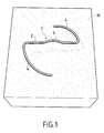
- a rigid fixing aid 1 is constituted a metal rod 4 mm in diameter and complex in shape.
- This one consists of a first part 2, substantially straight, 12 cm in length comprising a central projection 3 and extended at each of its two ends by a fraction of propeller constituting a second part 4.
- the two fractions of propeller are identical and of the same axis, passing through the center, that is to say the apex of projection 3, each being transformed from the other by rotation of 180 ° along this axis.
- the ends, not visible and located in the thickness of the glass wool 10, two propeller fractions are pointed in order to facilitate the penetration into it.
- the position shown is an intermediate anchoring position, in which the propeller fractions 4 have not yet fully penetrated the glass wool 10. From this position, a rotation of the fixing aid 1 along the axis of the propeller fractions has the effect of gradually penetrating the all of the propeller fractions 4 in the glass wool 10. Then in the position of fixing insulation 10 to a support, only the first part 2 of the auxiliary attachment 1 is located outside of the glass wool 10.
- Glass wool panels 80 mm thick and 50 kg / m 3 density are fixed on a concrete agglomerate support, using adhesive mortar pads, onto which a 10 mm plasterboard is glued. thick, composite products marketed by the Saint-Gobain Isover France Company under the trade name Calibel.
- An adhesive mortar sold under the name M.A.P. is used. by the company Placoplâtre, of which 25 kg are mixed with 13 to 13.5 liters of water. Beforehand, the location of the studs on the glass wool was pre-coated at the using the same mortar twice as diluted.
- Two panels, 2 m high and 1.2 m wide, are fixed edge to edge on the support.
- the studs are arranged regularly spaced using a template: on the height of 2m are distributed 5 rows of studs spaced in their center of 400 mm, the two extreme rows being 200 mm from the edges, while that over the width of 1.2 m are distributed 4 rows of studs spaced at their center of 300 mm, the two extreme rows being distant from the edges of 150 mm.
- the studs are calibrated by the template to 130 mm in diameter and 15 mm thick.
- each panel On the height of 2 m of each panel are here distributed 4 rows of studs spaced 500 mm apart, the two extreme rows being 250 mm apart edges; over the width of 1.2 m are distributed 3 rows of studs spaced 400 mm, the two extreme rows being 200 mm from the edges.
- the thickness of the studs is reduced to 100 mm. Wrenching in the same conditions that above are observed here only for a traction of 300 daN.
- the use of the fixing aids of the invention therefore made it possible to increase the pull-out resistance of the assembly constituted by the panels and their plasterboard, eliminating the pre-coating, reducing the number of plots from 20 to 12 and their mass by a third.
Landscapes
- Architecture (AREA)
- Physics & Mathematics (AREA)
- Engineering & Computer Science (AREA)
- Structural Engineering (AREA)
- Electromagnetism (AREA)
- Civil Engineering (AREA)
- Acoustics & Sound (AREA)
- Building Environments (AREA)
- Forklifts And Lifting Vehicles (AREA)
- Insulators (AREA)
- Insulation, Fastening Of Motor, Generator Windings (AREA)
- Piezo-Electric Or Mechanical Vibrators, Or Delay Or Filter Circuits (AREA)
- Thermistors And Varistors (AREA)
- Finishing Walls (AREA)
Abstract
Description
- l'isolant est un feutre ou matelas d'épaisseur comprise entre 10 et 150 mm ;
- l'isolant a une densité au moins égale à 40 kg/m3, cette densité pouvant par ailleurs atteindre des valeurs de l'ordre de 80 kg/m3, mais n'excédant que rarement 100 kg/m3, dans des applications particulières.
Claims (10)
- Produit d'isolation acoustique et/ou thermique comprenant un isolant (10) de densité au moins égale à 10 kg/m3 et des plots de colle de masse et répartition à la surface de l'isolant appropriées, caractérisé en ce qu'au moins un auxiliaire rigide de fixation (1) de l'isolant (10) sur un support comporte une première partie (2) noyée dans un plot de colle et une seconde partie (4) ancrée dans l'isolant (10).
- Produit selon la revendication 1, caractérisé en ce que l'isolant (10) est une laine minérale.
- Produit selon la revendication 1 ou 2, caractérisé en ce que les plots de colle sont répartis sur une première face principale de l'isolant (10), dont la seconde face principale est solidaire d'une plaque rigide.
- Produit selon la revendication 3, caractérisé en ce que ladite plaque rigide est une plaque de plâtre de 5 à 25 mm d'épaisseur.
- Produit selon l'une des revendications précédentes, caractérisé en ce que l'isolant (10) est un feutre ou matelas d'épaisseur comprise entre 10 et 150 mm.
- Produit selon l'une des revendications précédentes, caractérisé en ce que l'isolant (10) a une densité au moins égale à 40 kg/m3.
- Auxiliaire rigide de fixation (1) d'un isolant (10) sur un support, comprenant une première partie (2) apte à faire saillie par rapport à la surface de l'isolant (10) et à être noyée dans un plot de colle, et une seconde partie (4) simultanément apte à être ancrée dans l'isolant (10).
- Auxiliaire rigide de fixation (1) selon la revendication 7, caractérisé en ce que sa partie (4) apte à être ancrée dans l'isolant comprend une fraction d'hélice ou plusieurs identiques.
- Auxiliaire rigide de fixation (1) selon la revendication 7 ou 8, caractérisé en ce qu'il est métallique ou en matière plastique.
- Procédé de fixation d'un produit d'isolation acoustique et/ou thermique sur un support au moyen de plots de colle, caractérisé en ce que l'on ancre au moins un auxiliaire rigide de fixation (1) dans l'isolant (10), puis on le noie dans un plot de colle.
Applications Claiming Priority (2)
| Application Number | Priority Date | Filing Date | Title |
|---|---|---|---|
| FR0112088 | 2001-09-19 | ||
| FR0112088A FR2829779B1 (fr) | 2001-09-19 | 2001-09-19 | Fixation amelioree d'un isolant sur un support |
Publications (2)
| Publication Number | Publication Date |
|---|---|
| EP1295999A1 true EP1295999A1 (fr) | 2003-03-26 |
| EP1295999B1 EP1295999B1 (fr) | 2007-07-25 |
Family
ID=8867420
Family Applications (1)
| Application Number | Title | Priority Date | Filing Date |
|---|---|---|---|
| EP02292294A Expired - Lifetime EP1295999B1 (fr) | 2001-09-19 | 2002-09-18 | Fixation améliorée d'un isolant sur un support |
Country Status (4)
| Country | Link |
|---|---|
| EP (1) | EP1295999B1 (fr) |
| AT (1) | ATE368156T1 (fr) |
| DE (1) | DE60221330D1 (fr) |
| FR (1) | FR2829779B1 (fr) |
Citations (4)
| Publication number | Priority date | Publication date | Assignee | Title |
|---|---|---|---|---|
| US1967071A (en) * | 1932-11-05 | 1934-07-17 | Ind Patents Corp | Ceiling construction |
| FR2259194A1 (en) * | 1974-01-25 | 1975-08-22 | Saint Gobain | Glass faced fire resistant panel - has wire mesh embedded in adhesive between glass and core |
| US3967524A (en) * | 1975-05-01 | 1976-07-06 | Snow Kenneth T | Insulation block fastener |
| FR2678970A1 (fr) * | 1991-07-08 | 1993-01-15 | Fibralith Gie | Panneaux isolants a coller pour le batiment, et procede de doublage isolant d'une paroi. |
-
2001
- 2001-09-19 FR FR0112088A patent/FR2829779B1/fr not_active Expired - Fee Related
-
2002
- 2002-09-18 EP EP02292294A patent/EP1295999B1/fr not_active Expired - Lifetime
- 2002-09-18 DE DE60221330T patent/DE60221330D1/de not_active Expired - Lifetime
- 2002-09-18 AT AT02292294T patent/ATE368156T1/de not_active IP Right Cessation
Patent Citations (4)
| Publication number | Priority date | Publication date | Assignee | Title |
|---|---|---|---|---|
| US1967071A (en) * | 1932-11-05 | 1934-07-17 | Ind Patents Corp | Ceiling construction |
| FR2259194A1 (en) * | 1974-01-25 | 1975-08-22 | Saint Gobain | Glass faced fire resistant panel - has wire mesh embedded in adhesive between glass and core |
| US3967524A (en) * | 1975-05-01 | 1976-07-06 | Snow Kenneth T | Insulation block fastener |
| FR2678970A1 (fr) * | 1991-07-08 | 1993-01-15 | Fibralith Gie | Panneaux isolants a coller pour le batiment, et procede de doublage isolant d'une paroi. |
Also Published As
| Publication number | Publication date |
|---|---|
| FR2829779B1 (fr) | 2004-09-17 |
| ATE368156T1 (de) | 2007-08-15 |
| FR2829779A1 (fr) | 2003-03-21 |
| EP1295999B1 (fr) | 2007-07-25 |
| DE60221330D1 (de) | 2007-09-06 |
Similar Documents
| Publication | Publication Date | Title |
|---|---|---|
| FR2611778A1 (fr) | Plancher a collaboration bois-beton | |
| EP2435641A1 (fr) | Système d'isolation de bâtiments par l'extérieur | |
| FR2660341A1 (fr) | Materiau complexe d'isolation phonique et sol en faisant application. | |
| WO2006050604A1 (fr) | Isolateur acoustique anti-vibration pour plafond suspendu | |
| EP2225426B1 (fr) | Systeme d'isolation de bâtiments par l'exterieur | |
| CA2709833C (fr) | Facade semi-rideau | |
| FR2989704A1 (fr) | Elements de construction et construction de toiture | |
| WO2015067898A1 (fr) | Panneau pour murs de batiments a base de tiges de bambou | |
| EP1295999A1 (fr) | Fixation améliorée d'un isolant sur un support | |
| FR2553454A1 (fr) | Dispositif de revetement pour murs, sols, meubles et applications analogues | |
| FR2609742A1 (fr) | Dispositif permettant de fixer des panneaux composites comportant un materiau isolant non ou peu rigide sur une ossature bois ou metallique | |
| FR2978217A1 (fr) | Procede et systeme de fixation d'un objet a une facade | |
| CA2586524C (fr) | Isolateur acoustique anti-vibration pour plafond suspendu | |
| CA2327727A1 (fr) | Systeme de construction de panneaux d'assemblage et leur utilisation en vue de la realisation de constructions modulaires | |
| FR2609487A1 (fr) | Plaques en ceramique pourvues de moyens de fixation et leur procede de fabrication | |
| EP0507713A1 (fr) | Dispositif de cloison, en particulier à capacité coupe-feu pendant une longue durée | |
| FR3012489A1 (fr) | Moyen de fixation d'une ossature a une paroi | |
| FR3006348A1 (fr) | Ossature pour mur porteur | |
| EP3559367A1 (fr) | Systeme d'isolation thermique par l'exterieur constitue d'un mortier projete fortement isolant et procede de fabrication du systeme | |
| FR2589903A1 (fr) | Dispositif d'isolation de murs par l'exterieur. | |
| FR2972468A1 (fr) | Procede d'isolation | |
| EP1805379B1 (fr) | Doublage de paroi a resistance amelioree au choc | |
| FR2587269A1 (fr) | Procede et dispositif de fixation de parements sur du platre cellulaire et panneaux obtenus selon ce procede | |
| EP1741850B1 (fr) | Elément de raccordement de fourrures pour doublage de paroi | |
| EP2837749A1 (fr) | Procédé de fabrication de paroi composite |
Legal Events
| Date | Code | Title | Description |
|---|---|---|---|
| PUAI | Public reference made under article 153(3) epc to a published international application that has entered the european phase |
Free format text: ORIGINAL CODE: 0009012 |
|
| 17P | Request for examination filed |
Effective date: 20020923 |
|
| AK | Designated contracting states |
Kind code of ref document: A1 Designated state(s): AT BE BG CH CY CZ DE DK EE ES FI FR GB GR IE IT LI LU MC NL PT SE SK TR |
|
| AX | Request for extension of the european patent |
Extension state: AL LT LV MK RO SI |
|
| AKX | Designation fees paid |
Designated state(s): AT BE BG CH CY CZ DE DK EE ES FI FR GB GR IE IT LI LU MC NL PT SE SK TR |
|
| GRAP | Despatch of communication of intention to grant a patent |
Free format text: ORIGINAL CODE: EPIDOSNIGR1 |
|
| GRAS | Grant fee paid |
Free format text: ORIGINAL CODE: EPIDOSNIGR3 |
|
| GRAA | (expected) grant |
Free format text: ORIGINAL CODE: 0009210 |
|
| AK | Designated contracting states |
Kind code of ref document: B1 Designated state(s): AT BE BG CH CY CZ DE DK EE ES FI FR GB GR IE IT LI LU MC NL PT SE SK TR |
|
| REG | Reference to a national code |
Ref country code: GB Ref legal event code: FG4D Free format text: NOT ENGLISH |
|
| REG | Reference to a national code |
Ref country code: CH Ref legal event code: EP |
|
| REG | Reference to a national code |
Ref country code: IE Ref legal event code: FG4D Free format text: LANGUAGE OF EP DOCUMENT: FRENCH |
|
| REF | Corresponds to: |
Ref document number: 60221330 Country of ref document: DE Date of ref document: 20070906 Kind code of ref document: P |
|
| PG25 | Lapsed in a contracting state [announced via postgrant information from national office to epo] |
Ref country code: BG Free format text: LAPSE BECAUSE OF FAILURE TO SUBMIT A TRANSLATION OF THE DESCRIPTION OR TO PAY THE FEE WITHIN THE PRESCRIBED TIME-LIMIT Effective date: 20071025 Ref country code: NL Free format text: LAPSE BECAUSE OF FAILURE TO SUBMIT A TRANSLATION OF THE DESCRIPTION OR TO PAY THE FEE WITHIN THE PRESCRIBED TIME-LIMIT Effective date: 20070725 Ref country code: ES Free format text: LAPSE BECAUSE OF FAILURE TO SUBMIT A TRANSLATION OF THE DESCRIPTION OR TO PAY THE FEE WITHIN THE PRESCRIBED TIME-LIMIT Effective date: 20071105 Ref country code: FI Free format text: LAPSE BECAUSE OF FAILURE TO SUBMIT A TRANSLATION OF THE DESCRIPTION OR TO PAY THE FEE WITHIN THE PRESCRIBED TIME-LIMIT Effective date: 20070725 Ref country code: PT Free format text: LAPSE BECAUSE OF FAILURE TO SUBMIT A TRANSLATION OF THE DESCRIPTION OR TO PAY THE FEE WITHIN THE PRESCRIBED TIME-LIMIT Effective date: 20071226 |
|
| NLV1 | Nl: lapsed or annulled due to failure to fulfill the requirements of art. 29p and 29m of the patents act | ||
| GBV | Gb: ep patent (uk) treated as always having been void in accordance with gb section 77(7)/1977 [no translation filed] |
Effective date: 20070725 |
|
| PG25 | Lapsed in a contracting state [announced via postgrant information from national office to epo] |
Ref country code: AT Free format text: LAPSE BECAUSE OF FAILURE TO SUBMIT A TRANSLATION OF THE DESCRIPTION OR TO PAY THE FEE WITHIN THE PRESCRIBED TIME-LIMIT Effective date: 20070725 |
|
| REG | Reference to a national code |
Ref country code: IE Ref legal event code: FD4D |
|
| PG25 | Lapsed in a contracting state [announced via postgrant information from national office to epo] |
Ref country code: DE Free format text: LAPSE BECAUSE OF FAILURE TO SUBMIT A TRANSLATION OF THE DESCRIPTION OR TO PAY THE FEE WITHIN THE PRESCRIBED TIME-LIMIT Effective date: 20071026 Ref country code: DK Free format text: LAPSE BECAUSE OF FAILURE TO SUBMIT A TRANSLATION OF THE DESCRIPTION OR TO PAY THE FEE WITHIN THE PRESCRIBED TIME-LIMIT Effective date: 20070725 Ref country code: MC Free format text: LAPSE BECAUSE OF NON-PAYMENT OF DUE FEES Effective date: 20070930 Ref country code: GR Free format text: LAPSE BECAUSE OF FAILURE TO SUBMIT A TRANSLATION OF THE DESCRIPTION OR TO PAY THE FEE WITHIN THE PRESCRIBED TIME-LIMIT Effective date: 20071026 |
|
| REG | Reference to a national code |
Ref country code: CH Ref legal event code: PL |
|
| PG25 | Lapsed in a contracting state [announced via postgrant information from national office to epo] |
Ref country code: GB Free format text: LAPSE BECAUSE OF FAILURE TO SUBMIT A TRANSLATION OF THE DESCRIPTION OR TO PAY THE FEE WITHIN THE PRESCRIBED TIME-LIMIT Effective date: 20070725 Ref country code: IE Free format text: LAPSE BECAUSE OF FAILURE TO SUBMIT A TRANSLATION OF THE DESCRIPTION OR TO PAY THE FEE WITHIN THE PRESCRIBED TIME-LIMIT Effective date: 20070725 Ref country code: SK Free format text: LAPSE BECAUSE OF FAILURE TO SUBMIT A TRANSLATION OF THE DESCRIPTION OR TO PAY THE FEE WITHIN THE PRESCRIBED TIME-LIMIT Effective date: 20070725 Ref country code: CZ Free format text: LAPSE BECAUSE OF FAILURE TO SUBMIT A TRANSLATION OF THE DESCRIPTION OR TO PAY THE FEE WITHIN THE PRESCRIBED TIME-LIMIT Effective date: 20070725 |
|
| PLBE | No opposition filed within time limit |
Free format text: ORIGINAL CODE: 0009261 |
|
| STAA | Information on the status of an ep patent application or granted ep patent |
Free format text: STATUS: NO OPPOSITION FILED WITHIN TIME LIMIT |
|
| PG25 | Lapsed in a contracting state [announced via postgrant information from national office to epo] |
Ref country code: SE Free format text: LAPSE BECAUSE OF FAILURE TO SUBMIT A TRANSLATION OF THE DESCRIPTION OR TO PAY THE FEE WITHIN THE PRESCRIBED TIME-LIMIT Effective date: 20071025 |
|
| 26N | No opposition filed |
Effective date: 20080428 |
|
| PG25 | Lapsed in a contracting state [announced via postgrant information from national office to epo] |
Ref country code: LI Free format text: LAPSE BECAUSE OF NON-PAYMENT OF DUE FEES Effective date: 20070930 Ref country code: CH Free format text: LAPSE BECAUSE OF NON-PAYMENT OF DUE FEES Effective date: 20070930 |
|
| PG25 | Lapsed in a contracting state [announced via postgrant information from national office to epo] |
Ref country code: EE Free format text: LAPSE BECAUSE OF FAILURE TO SUBMIT A TRANSLATION OF THE DESCRIPTION OR TO PAY THE FEE WITHIN THE PRESCRIBED TIME-LIMIT Effective date: 20070725 |
|
| PG25 | Lapsed in a contracting state [announced via postgrant information from national office to epo] |
Ref country code: CY Free format text: LAPSE BECAUSE OF FAILURE TO SUBMIT A TRANSLATION OF THE DESCRIPTION OR TO PAY THE FEE WITHIN THE PRESCRIBED TIME-LIMIT Effective date: 20070725 |
|
| PG25 | Lapsed in a contracting state [announced via postgrant information from national office to epo] |
Ref country code: LU Free format text: LAPSE BECAUSE OF NON-PAYMENT OF DUE FEES Effective date: 20070918 |
|
| PG25 | Lapsed in a contracting state [announced via postgrant information from national office to epo] |
Ref country code: TR Free format text: LAPSE BECAUSE OF FAILURE TO SUBMIT A TRANSLATION OF THE DESCRIPTION OR TO PAY THE FEE WITHIN THE PRESCRIBED TIME-LIMIT Effective date: 20070725 |
|
| PG25 | Lapsed in a contracting state [announced via postgrant information from national office to epo] |
Ref country code: IT Free format text: LAPSE BECAUSE OF NON-PAYMENT OF DUE FEES Effective date: 20070930 |
|
| REG | Reference to a national code |
Ref country code: FR Ref legal event code: PLFP Year of fee payment: 14 |
|
| PGFP | Annual fee paid to national office [announced via postgrant information from national office to epo] |
Ref country code: FR Payment date: 20150909 Year of fee payment: 14 |
|
| REG | Reference to a national code |
Ref country code: FR Ref legal event code: ST Effective date: 20170531 |
|
| PG25 | Lapsed in a contracting state [announced via postgrant information from national office to epo] |
Ref country code: FR Free format text: LAPSE BECAUSE OF NON-PAYMENT OF DUE FEES Effective date: 20160930 |
|
| PGFP | Annual fee paid to national office [announced via postgrant information from national office to epo] |
Ref country code: BE Payment date: 20200817 Year of fee payment: 19 |
|
| REG | Reference to a national code |
Ref country code: BE Ref legal event code: MM Effective date: 20210930 |
|
| PG25 | Lapsed in a contracting state [announced via postgrant information from national office to epo] |
Ref country code: BE Free format text: LAPSE BECAUSE OF NON-PAYMENT OF DUE FEES Effective date: 20210930 |