EP1295692A1 - Method of manufacturing a form made of concrete - Google Patents
Method of manufacturing a form made of concrete Download PDFInfo
- Publication number
- EP1295692A1 EP1295692A1 EP02019540A EP02019540A EP1295692A1 EP 1295692 A1 EP1295692 A1 EP 1295692A1 EP 02019540 A EP02019540 A EP 02019540A EP 02019540 A EP02019540 A EP 02019540A EP 1295692 A1 EP1295692 A1 EP 1295692A1
- Authority
- EP
- European Patent Office
- Prior art keywords
- concrete
- mold
- frame
- receiver
- pressure
- Prior art date
- Legal status (The legal status is an assumption and is not a legal conclusion. Google has not performed a legal analysis and makes no representation as to the accuracy of the status listed.)
- Withdrawn
Links
- 238000004519 manufacturing process Methods 0.000 title claims description 12
- 238000003825 pressing Methods 0.000 claims description 4
- 238000002347 injection Methods 0.000 description 5
- 239000007924 injection Substances 0.000 description 5
- XEEYBQQBJWHFJM-UHFFFAOYSA-N Iron Chemical compound [Fe] XEEYBQQBJWHFJM-UHFFFAOYSA-N 0.000 description 4
- 238000001746 injection moulding Methods 0.000 description 4
- 239000000463 material Substances 0.000 description 3
- 239000011347 resin Substances 0.000 description 3
- 229920005989 resin Polymers 0.000 description 3
- 229910052742 iron Inorganic materials 0.000 description 2
- 239000002184 metal Substances 0.000 description 2
- 229910052751 metal Inorganic materials 0.000 description 2
- 238000000465 moulding Methods 0.000 description 2
- 238000013022 venting Methods 0.000 description 2
- 238000010276 construction Methods 0.000 description 1
- 230000005484 gravity Effects 0.000 description 1
- 229910052500 inorganic mineral Inorganic materials 0.000 description 1
- 239000002932 luster Substances 0.000 description 1
- 150000002739 metals Chemical class 0.000 description 1
- 238000000034 method Methods 0.000 description 1
- 239000011707 mineral Substances 0.000 description 1
- 239000004575 stone Substances 0.000 description 1
- 239000002023 wood Substances 0.000 description 1
Images

Classifications
-
- B—PERFORMING OPERATIONS; TRANSPORTING
- B28—WORKING CEMENT, CLAY, OR STONE
- B28B—SHAPING CLAY OR OTHER CERAMIC COMPOSITIONS; SHAPING SLAG; SHAPING MIXTURES CONTAINING CEMENTITIOUS MATERIAL, e.g. PLASTER
- B28B1/00—Producing shaped prefabricated articles from the material
- B28B1/08—Producing shaped prefabricated articles from the material by vibrating or jolting
- B28B1/10—Producing shaped prefabricated articles from the material by vibrating or jolting and applying pressure otherwise than by the use of presses
-
- B—PERFORMING OPERATIONS; TRANSPORTING
- B29—WORKING OF PLASTICS; WORKING OF SUBSTANCES IN A PLASTIC STATE IN GENERAL
- B29C—SHAPING OR JOINING OF PLASTICS; SHAPING OF MATERIAL IN A PLASTIC STATE, NOT OTHERWISE PROVIDED FOR; AFTER-TREATMENT OF THE SHAPED PRODUCTS, e.g. REPAIRING
- B29C33/00—Moulds or cores; Details thereof or accessories therefor
- B29C33/38—Moulds or cores; Details thereof or accessories therefor characterised by the material or the manufacturing process
-
- B—PERFORMING OPERATIONS; TRANSPORTING
- B29—WORKING OF PLASTICS; WORKING OF SUBSTANCES IN A PLASTIC STATE IN GENERAL
- B29K—INDEXING SCHEME ASSOCIATED WITH SUBCLASSES B29B, B29C OR B29D, RELATING TO MOULDING MATERIALS OR TO MATERIALS FOR MOULDS, REINFORCEMENTS, FILLERS OR PREFORMED PARTS, e.g. INSERTS
- B29K2709/00—Use of inorganic materials not provided for in groups B29K2703/00 - B29K2707/00, for preformed parts, e.g. for inserts
- B29K2709/06—Concrete
-
- Y—GENERAL TAGGING OF NEW TECHNOLOGICAL DEVELOPMENTS; GENERAL TAGGING OF CROSS-SECTIONAL TECHNOLOGIES SPANNING OVER SEVERAL SECTIONS OF THE IPC; TECHNICAL SUBJECTS COVERED BY FORMER USPC CROSS-REFERENCE ART COLLECTIONS [XRACs] AND DIGESTS
- Y10—TECHNICAL SUBJECTS COVERED BY FORMER USPC
- Y10S—TECHNICAL SUBJECTS COVERED BY FORMER USPC CROSS-REFERENCE ART COLLECTIONS [XRACs] AND DIGESTS
- Y10S425/00—Plastic article or earthenware shaping or treating: apparatus
- Y10S425/812—Venting
Definitions
- the present invention relates to a method of manufacturing a concrete form or mold which can be used as an injection mold or the like.
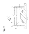
- FIG. 2 shows such a conventional mold or form manufacturing method in which a master model 1 is enclosed by a frame 2 and concrete 5 is filled inside the frame 2 through an filling hole 4 provided on a top section 3 of the frame 2. After the concrete 5 hardens, the frame 2 is removed from the concrete 5 to provide a concrete form or mold.
- Reference numeral 2a is a small vent hole for mold venting.
- Fig. 3 shows an example in which such a concrete form or mold is used as an injection mold.
- This injection mold is provided with a movable mold 6 and a stationary mold 7 and molding resin is filled in a cavity 8 formed by both the movable and stationary molds 6, 7 through an filling hole 7a by an injection machine.
- the movable mold 6 and the stationary mold 7 are the above-mentioned concrete forms or molds, wherein the movable mold 6 is provided with a mold surface 6a copied from the master model 1 to provide an external appearance surface of a molded article.
- the concrete form or mold has a peculiar characteristic whereby pinholes can be easily produced on the surface thereof. Inferior outer appearance of the molded article often results from the pinholes generated on the mold surface.
- the pinhole 9 may be formed on the surface of the mold surface 6a facing the cavity 8 parallel to the mold opening direction. If part of the molding resin 13 enters the pinhole 9 during injection molding and hardens there, there is some possibility that the movable mold 6 will not be easily opened. Accordingly, it was also necessary to decrease the generation of the pinholes.
- a method of manufacturing a concrete form or mold by providing a frame on a master model and filling concrete into the frame, which comprises the steps of filling the concrete more than the predetermined cubic volume into the frame and then, forcibly applying pressure to the concrete to the predetermined cubit volume.
- the method of manufacturing a concrete form or mold according to claim 1 is provided, in which the frame is provided with a body section for receiving concrete of the predetermined cubic volume and a concrete receiver for receiving concrete more than the predetermined cubic volume, the method comprising the steps of causing the concrete to overflow from the body into the concrete receiver and then, forcibly applying pressure to the overflowed concrete received within the concrete receiver in the direction of the inside of the body section.
- the concrete under pressure can enter the detailed sections of the surface of the master model to faithfully copy the shape of the master model. This can not only reduce a great deal of time for correction of the concrete form or mold after manufactured, but also reduce a great deal of cost. Since the concrete can be fully filled into the frame, it is possible to prevent the concrete from being improperly filled into the frame and as a result, durability of the form or mold can also be improved.
- the copied surface of the concrete form or mold is made fine and smooth and generation of the pinholes on the mold surface of the concrete form or mold can be reduced by the forcible application of pressure. Accordingly, it is not only possible to reduce inferior external appearance of the mold article resulting from the pinholes, but also to make the form or mold opening smooth during injection molding.
- the body section of the frame is provided with the concrete receiver, and when the concrete is filled into the frame, the concrete is caused to overflow in the concrete receiver so that it can be filled beyond the predetermined cubic volume. Then, forcible pressure is applied to the concrete overflowed within the concrete receiver to make the final filling quantity of the concrete within the body section to be the predetermined cubic volume. It is therefore possible to efficiently perform the forcible application of pressure to the concrete.
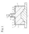
- Fig. 1 shows a method of manufacturing a female mold which is used as a movable mold 6 in Fig. 3.
- a frame 2 mounted on a master model 1 is integrally formed with a cylindrical concrete receiver 10 projecting upwardly from a top section 3 of the frame 2.
- the concrete receiver 10 communicates with the inside and outside of the frame 2.
- Sections of the frame 2 excluding the concrete receiver 10 form a body section 11 and are adapted to receive the concrete of the predetermined cubic volume corresponding to at least the cubic volume of the form or mold to be completed.
- the frame 2 is made of a suitable material with relatively stiffness properties such as metal, resin or wood in a substantially vessel-shape.
- the frame 2 is widely opened on the master model 1 side and integrally formed with a concrete receiver 10 at the top section 3 thereof on the other side which communicates with the inside of the frame 2.
- the volume of the concrete receiver 10 can be freely set according to the pressure condition to the concrete 5 filled inside the frame 2. For example, it can be set to about ⁇ 100 x height 200 (mm) relative to the frame 2 in which the predetermined cubic volume of the concrete 5 to be filled into the body section 11 is about 90 lit.
- the top section 3 is also provided with a small vent hole 2a of about ⁇ 0.5 mm ⁇ 1 mm for mold venting in selected number and place.
- the concrete receiver 10 is open at its upper section through which a heavy weight 12 is inserted as a pressure member.
- the weight 12 can also be optionally set according to necessary pressure condition, but in the present embodiment condition, a round bar made of iron of about ⁇ 95 x 300 (mm) is used. In this case, the weight is about 16 kg.
- the weight 12 can be selected from any material, but it is desirable that the weight 12 be selected from various metals such as iron or mineral material such as stone.
- a frame 2 is mounted on a master model 1 and concrete 5 is filled into the frame 2 through a concrete receiver 10 at normal pressure or at lower pressure than the subsequent forced pressure.
- the concrete 5 more than the predetermined cubic volume is filled into the frame 2 to cause part of the concrete 5 to be overflowed into the concrete receiver 10 from a body section 11.
- a weight 12 is inserted through the upper section of the concrete receiver 10 to apply pressure to the concrete 5 overflowed from the body section 11.
- the concrete 5 within the body section 11 is caused to fully contact the surface of the master model 1 under pressure.
- the frame 2 is removed from the concrete 5 to obtain a concrete form or mold such as a movable mold 6 shown in Fig. 3.
- the mold surface of the concrete form or mold is caused to be fine under pressure and improve the luster. Since the mold surface can also faithfully copy the shape of the master model, it is possible to reduce the time and cost necessary to correct the concrete form or mold after manufactured. Since sufficient quantity of the concrete can be filled into the frame, it is possible to prevent the inferior or improper filling of the concrete and improve durability of the form or mold.
- the copied surface of the concrete form or mold is caused to be fine and smooth by forced pressure and the generation of pinholes on the mold surface of the concrete form or mold can also be reduced. Accordingly, it is possible to reduce inferior external appearance of the molded article resulting from the pinholes and make the mold opening operation smooth during injection molding. If a vibrator is used during application of forced pressure, filling of the concrete can be performed more finely and it is possible to further reduce the generation of pinholes.
- the concrete receiver 10 is provided on the body section 11 of the frame 2. Then, pressure is forcibly applied to the concrete 5 overflowed within the concrete receiver 10 by the weight 12 to set the filling quantity of the concrete 5 within the body section 11 at the predetermined cubic volume. Accordingly, it is possible to efficiently perform the forcible application of pressure in a simple construction.
- the pressure member is not limited to the weight 12 using gravity, but pressure can be applied to the concrete by a pressure device such as a cylinder device. Accordingly, the concrete receiver 10 can be provided on the side of the frame 2 to apply pressure by the cylinder device. Further, if the entire top section 3 of the frame 2 can be vertically moved, it is also possible to perform forcible application of pressure to the concrete by applying pressure to the top section 3 itself.
- a cylindrical concrete receiver 10 is caused to project from a top section 3 of a body section 11 forming a frame 2.
- part of the concrete 5 is caused to overflow inside the concrete receiver 10 and then, pressure is applied to the concrete 5 overflowed in the concrete receiver 10 by a weight 12.
Landscapes
- Engineering & Computer Science (AREA)
- Manufacturing & Machinery (AREA)
- Mechanical Engineering (AREA)
- Chemical & Material Sciences (AREA)
- Ceramic Engineering (AREA)
- Moulds, Cores, Or Mandrels (AREA)
- Press-Shaping Or Shaping Using Conveyers (AREA)
- Moulds For Moulding Plastics Or The Like (AREA)
- Devices For Post-Treatments, Processing, Supply, Discharge, And Other Processes (AREA)
- Manufacturing Of Tubular Articles Or Embedded Moulded Articles (AREA)
Abstract
Description
- The present invention relates to a method of manufacturing a concrete form or mold which can be used as an injection mold or the like.
- Manufacture a mold or a form using concrete to reduce mold expenses such as injection molding is known. Fig. 2 shows such a conventional mold or form manufacturing method in which a master model 1 is enclosed by a
frame 2 andconcrete 5 is filled inside theframe 2 through anfilling hole 4 provided on atop section 3 of theframe 2. After theconcrete 5 hardens, theframe 2 is removed from theconcrete 5 to provide a concrete form or mold.Reference numeral 2a is a small vent hole for mold venting. - Fig. 3 shows an example in which such a concrete form or mold is used as an injection mold. This injection mold is provided with a
movable mold 6 and astationary mold 7 and molding resin is filled in a cavity 8 formed by both the movable andstationary molds filling hole 7a by an injection machine. Themovable mold 6 and thestationary mold 7 are the above-mentioned concrete forms or molds, wherein themovable mold 6 is provided with amold surface 6a copied from the master model 1 to provide an external appearance surface of a molded article. - In the case of the concrete form or mold, when the concrete is filled into the
frame 2, it is not possible to faithfully copy the shape of the master model 1 unless the concrete is fully filled therein. In this case, correction of the concrete form or mold is required after manufactured. This not only requires a great deal of time and labor, but also costs a great deal. It was therefore necessary to establish a method of manufacturing the concrete form or mold which makes it possible to fully fill the concrete in theframe 2. - Further, the concrete form or mold has a peculiar characteristic whereby pinholes can be easily produced on the surface thereof. Inferior outer appearance of the molded article often results from the pinholes generated on the mold surface. As shown in Fig. 3, the
pinhole 9 may be formed on the surface of themold surface 6a facing the cavity 8 parallel to the mold opening direction. If part of themolding resin 13 enters thepinhole 9 during injection molding and hardens there, there is some possibility that themovable mold 6 will not be easily opened. Accordingly, it was also necessary to decrease the generation of the pinholes. - It is therefore an object of the present invention to realize these demands or requests.
- To solve the problems, according to the invention of claim 1, there is provided a method of manufacturing a concrete form or mold by providing a frame on a master model and filling concrete into the frame, which comprises the steps of filling the concrete more than the predetermined cubic volume into the frame and then, forcibly applying pressure to the concrete to the predetermined cubit volume.
- According to the invention of
claim 2, the method of manufacturing a concrete form or mold according to claim 1 is provided, in which the frame is provided with a body section for receiving concrete of the predetermined cubic volume and a concrete receiver for receiving concrete more than the predetermined cubic volume, the method comprising the steps of causing the concrete to overflow from the body into the concrete receiver and then, forcibly applying pressure to the overflowed concrete received within the concrete receiver in the direction of the inside of the body section. - According to the invention of claim 1, when the concrete is filled into the frame, the concrete more than the predetermined cubic volume is filled therein and then, the pressure is forcibly applied to the concrete to the predetermined cubic volume. Accordingly, the concrete under pressure can enter the detailed sections of the surface of the master model to faithfully copy the shape of the master model. This can not only reduce a great deal of time for correction of the concrete form or mold after manufactured, but also reduce a great deal of cost. Since the concrete can be fully filled into the frame, it is possible to prevent the concrete from being improperly filled into the frame and as a result, durability of the form or mold can also be improved.
- The copied surface of the concrete form or mold is made fine and smooth and generation of the pinholes on the mold surface of the concrete form or mold can be reduced by the forcible application of pressure. Accordingly, it is not only possible to reduce inferior external appearance of the mold article resulting from the pinholes, but also to make the form or mold opening smooth during injection molding.
- According to the invention of
claim 2, the body section of the frame is provided with the concrete receiver, and when the concrete is filled into the frame, the concrete is caused to overflow in the concrete receiver so that it can be filled beyond the predetermined cubic volume. Then, forcible pressure is applied to the concrete overflowed within the concrete receiver to make the final filling quantity of the concrete within the body section to be the predetermined cubic volume. It is therefore possible to efficiently perform the forcible application of pressure to the concrete. - The above and other objects, features and advantages of the present invention will become more apparent from the following description when taken in conjunction with the accompanying drawings.
- Fig. 1 is a view showing a manufacturing method according to an embodiment of the present invention;
- Fig. 2 is a view showing a conventional manufacturing method; and
- Fig. 3 is a cross-sectional view of an injection mold using a concrete form or mold.
-
- One embodiment of the present invention will now be explained with reference to Fig. 1. The same reference numerals are used to the parts common to the conventional examples. Fig. 1 shows a method of manufacturing a female mold which is used as a
movable mold 6 in Fig. 3. Aframe 2 mounted on a master model 1 is integrally formed with acylindrical concrete receiver 10 projecting upwardly from atop section 3 of theframe 2. Theconcrete receiver 10 communicates with the inside and outside of theframe 2. Sections of theframe 2 excluding theconcrete receiver 10 form abody section 11 and are adapted to receive the concrete of the predetermined cubic volume corresponding to at least the cubic volume of the form or mold to be completed. - The
frame 2 is made of a suitable material with relatively stiffness properties such as metal, resin or wood in a substantially vessel-shape. Theframe 2 is widely opened on the master model 1 side and integrally formed with aconcrete receiver 10 at thetop section 3 thereof on the other side which communicates with the inside of theframe 2. The volume of theconcrete receiver 10 can be freely set according to the pressure condition to theconcrete 5 filled inside theframe 2. For example, it can be set to about 100 x height 200 (mm) relative to theframe 2 in which the predetermined cubic volume of theconcrete 5 to be filled into thebody section 11 is about 90 lit. Thetop section 3 is also provided with asmall vent hole 2a of about 0.5 mm ∼ 1 mm for mold venting in selected number and place. - The
concrete receiver 10 is open at its upper section through which aheavy weight 12 is inserted as a pressure member. Theweight 12 can also be optionally set according to necessary pressure condition, but in the present embodiment condition, a round bar made of iron of about 95 x 300 (mm) is used. In this case, the weight is about 16 kg. Theweight 12 can be selected from any material, but it is desirable that theweight 12 be selected from various metals such as iron or mineral material such as stone. - Operation of the present embodiment will now be explained. In Fig. 1, a
frame 2 is mounted on a master model 1 andconcrete 5 is filled into theframe 2 through aconcrete receiver 10 at normal pressure or at lower pressure than the subsequent forced pressure. In this case, theconcrete 5 more than the predetermined cubic volume is filled into theframe 2 to cause part of theconcrete 5 to be overflowed into theconcrete receiver 10 from abody section 11. Then, aweight 12 is inserted through the upper section of theconcrete receiver 10 to apply pressure to theconcrete 5 overflowed from thebody section 11. - In this manner, the
concrete 5 within thebody section 11 is caused to fully contact the surface of the master model 1 under pressure. After theconcrete 5 hardens due to setting, theframe 2 is removed from theconcrete 5 to obtain a concrete form or mold such as amovable mold 6 shown in Fig. 3. - In this case, the mold surface of the concrete form or mold is caused to be fine under pressure and improve the luster. Since the mold surface can also faithfully copy the shape of the master model, it is possible to reduce the time and cost necessary to correct the concrete form or mold after manufactured. Since sufficient quantity of the concrete can be filled into the frame, it is possible to prevent the inferior or improper filling of the concrete and improve durability of the form or mold.
- The copied surface of the concrete form or mold is caused to be fine and smooth by forced pressure and the generation of pinholes on the mold surface of the concrete form or mold can also be reduced. Accordingly, it is possible to reduce inferior external appearance of the molded article resulting from the pinholes and make the mold opening operation smooth during injection molding. If a vibrator is used during application of forced pressure, filling of the concrete can be performed more finely and it is possible to further reduce the generation of pinholes.
- Further, the
concrete receiver 10 is provided on thebody section 11 of theframe 2. Then, pressure is forcibly applied to theconcrete 5 overflowed within theconcrete receiver 10 by theweight 12 to set the filling quantity of theconcrete 5 within thebody section 11 at the predetermined cubic volume. Accordingly, it is possible to efficiently perform the forcible application of pressure in a simple construction. - Location and shape of the
concrete receiver 10 can be optionally determined. The pressure member is not limited to theweight 12 using gravity, but pressure can be applied to the concrete by a pressure device such as a cylinder device. Accordingly, theconcrete receiver 10 can be provided on the side of theframe 2 to apply pressure by the cylinder device. Further, if the entiretop section 3 of theframe 2 can be vertically moved, it is also possible to perform forcible application of pressure to the concrete by applying pressure to thetop section 3 itself. - A cylindrical
concrete receiver 10 is caused to project from atop section 3 of abody section 11 forming aframe 2. When concrete 5 is filled in thebody section 11, part of theconcrete 5 is caused to overflow inside theconcrete receiver 10 and then, pressure is applied to theconcrete 5 overflowed in theconcrete receiver 10 by aweight 12.
Claims (2)
- A method of manufacturing a concrete form by providing a frame on a master model and filling concrete into the frame, comprising the steps of filling the concrete more than the predetermined cubic volume into the frame and then forcibly applying pressure to the concrete to the predetermined cubic volume.
- The method of manufacturing a concrete form according to claim 1, wherein the frame is provided with a body section for receiving the concrete of the predetermined cubic volume and a concrete receiver for receiving the concrete more than the predetermined cubic volume, and wherein when the concrete is filled into the frame, the concrete is caused to overflow into the concrete receiver from the body section and then, forcible pressure is applied to the concrete overflowed within the concrete receiver in the direction of the inside of the body section.
Applications Claiming Priority (2)
| Application Number | Priority Date | Filing Date | Title |
|---|---|---|---|
| JP2001286617 | 2001-09-20 | ||
| JP2001286617A JP3839289B2 (en) | 2001-09-20 | 2001-09-20 | Concrete mold manufacturing method |
Publications (1)
| Publication Number | Publication Date |
|---|---|
| EP1295692A1 true EP1295692A1 (en) | 2003-03-26 |
Family
ID=19109563
Family Applications (1)
| Application Number | Title | Priority Date | Filing Date |
|---|---|---|---|
| EP02019540A Withdrawn EP1295692A1 (en) | 2001-09-20 | 2002-08-30 | Method of manufacturing a form made of concrete |
Country Status (6)
| Country | Link |
|---|---|
| US (1) | US6805819B2 (en) |
| EP (1) | EP1295692A1 (en) |
| JP (1) | JP3839289B2 (en) |
| CA (1) | CA2434738C (en) |
| MX (1) | MXPA03007379A (en) |
| WO (1) | WO2003026865A1 (en) |
Cited By (4)
| Publication number | Priority date | Publication date | Assignee | Title |
|---|---|---|---|---|
| EP2033757A1 (en) * | 2007-09-07 | 2009-03-11 | Deutsches Zentrum für Luft- und Raumfahrt e.V. | Method and forming tool for producing components, in particular those made of fibre compound materials |
| EP2025488B1 (en) * | 2007-08-09 | 2011-03-16 | Max Bögl Fertigteilwerke GmbH & Co. KG | Mould and method for manufacturing a mould |
| NL2012089C2 (en) * | 2014-01-15 | 2015-07-16 | Univ Delft Tech | Sub optimal elements. |
| CN111705568A (en) * | 2020-06-30 | 2020-09-25 | 吴丹 | Construction method for smart city construction rail traffic engineering |
Families Citing this family (4)
| Publication number | Priority date | Publication date | Assignee | Title |
|---|---|---|---|---|
| US7530203B1 (en) * | 2004-11-05 | 2009-05-12 | Swa Holding Company, Inc. | Pre-cast concrete wall with truss ledge |
| US20090321991A1 (en) * | 2008-06-25 | 2009-12-31 | Caroti Gino P N | Mold for making a masonry block and method for making a masonry block |
| WO2013040495A1 (en) | 2011-09-16 | 2013-03-21 | Goss Construction, Inc. | Concrete forming systems and methods |
| TWI635942B (en) * | 2017-09-08 | 2018-09-21 | 行政院原子能委員會核能研究所 | Drawing method and structure of patterns for low-level radioactive waste disposal container |
Citations (4)
| Publication number | Priority date | Publication date | Assignee | Title |
|---|---|---|---|---|
| GB516226A (en) * | 1938-06-13 | 1939-12-28 | Ernest Clarke | Improvements in or relating to moulding apparatus adapted particularly for moulding bricks or blocks of concrete or the like |
| US3638299A (en) * | 1968-12-30 | 1972-02-01 | Ici Ltd | Process for the production of molds |
| EP0052380A2 (en) * | 1980-11-19 | 1982-05-26 | Aktieselskabet Aalborg Portland-Cement-Fabrik | Tool for shaping articles |
| EP0979717A1 (en) * | 1998-08-05 | 2000-02-16 | STOLA S.p.A. | Method for the manufacture of a mould for use in injection moulding of components of plastic material |
Family Cites Families (15)
| Publication number | Priority date | Publication date | Assignee | Title |
|---|---|---|---|---|
| US3670066A (en) * | 1969-11-10 | 1972-06-13 | Emery I Valyi | Method of compression molding a thermoplastic article with walls of variable thickness |
| JPS565722A (en) * | 1979-06-27 | 1981-01-21 | Sekisui Chem Co Ltd | Manufacturing of mold of simple construction |
| JPS63296905A (en) * | 1987-05-29 | 1988-12-05 | Nissan Motor Co Ltd | Manufacture of molding tool made of concrete |
| FR2640168B2 (en) * | 1988-08-02 | 1994-09-02 | Chausson Usines Sa | PROCESS FOR THE MANUFACTURE OF RESIN CONCRETE TOOLS FOR FORMING, PARTICULARLY STAMPING, CUTTING AND THE LIKE, OF METAL SHEET PARTS |
| FR2660237B1 (en) * | 1990-04-02 | 1992-09-04 | Savoie Refractaires | CONCRETE COMPOSITION FOR MOLDS, MOLD AND METHOD FOR MANUFACTURING A MOLD. |
| JPH05104588A (en) * | 1991-10-15 | 1993-04-27 | Takamatsu Kikai Kogyo Kk | Manufacture of injection molding die using metallic resin concrete |
| JPH05318428A (en) * | 1992-05-22 | 1993-12-03 | C C A Kk | Method for producing molded object under pressure |
| JPH0852714A (en) * | 1992-07-13 | 1996-02-27 | Nippon Segumento Kogyo Kk | Manufacture of concrete segment |
| JP2748086B2 (en) | 1993-11-10 | 1998-05-06 | 荏原商事株式会社 | Method, apparatus and form for producing resin concrete product |
| TW279141B (en) * | 1994-10-07 | 1996-06-21 | Sintokogio Ltd | |
| US6106274A (en) * | 1995-08-30 | 2000-08-22 | The Budd Company | Molding apparatus with charge overflow |
| DE19531709A1 (en) * | 1995-08-30 | 1997-03-06 | Battenfeld Gmbh | Method and device for manufacturing plastic objects |
| JPH08309760A (en) * | 1996-05-15 | 1996-11-26 | Maeda Seikan Kk | Production of mold for molding thermosetting resin product |
| US6103150A (en) * | 1998-03-11 | 2000-08-15 | The Budd Company | Molding overflow feedback method |
| JP3603257B2 (en) * | 1999-06-08 | 2004-12-22 | 株式会社Inax | Manufacturing method of resin products |
-
2001
- 2001-09-20 JP JP2001286617A patent/JP3839289B2/en not_active Expired - Fee Related
-
2002
- 2002-08-27 WO PCT/JP2002/008592 patent/WO2003026865A1/en not_active Ceased
- 2002-08-27 CA CA002434738A patent/CA2434738C/en not_active Expired - Fee Related
- 2002-08-27 MX MXPA03007379A patent/MXPA03007379A/en active IP Right Grant
- 2002-08-30 EP EP02019540A patent/EP1295692A1/en not_active Withdrawn
- 2002-09-09 US US10/237,056 patent/US6805819B2/en not_active Expired - Fee Related
Patent Citations (4)
| Publication number | Priority date | Publication date | Assignee | Title |
|---|---|---|---|---|
| GB516226A (en) * | 1938-06-13 | 1939-12-28 | Ernest Clarke | Improvements in or relating to moulding apparatus adapted particularly for moulding bricks or blocks of concrete or the like |
| US3638299A (en) * | 1968-12-30 | 1972-02-01 | Ici Ltd | Process for the production of molds |
| EP0052380A2 (en) * | 1980-11-19 | 1982-05-26 | Aktieselskabet Aalborg Portland-Cement-Fabrik | Tool for shaping articles |
| EP0979717A1 (en) * | 1998-08-05 | 2000-02-16 | STOLA S.p.A. | Method for the manufacture of a mould for use in injection moulding of components of plastic material |
Cited By (4)
| Publication number | Priority date | Publication date | Assignee | Title |
|---|---|---|---|---|
| EP2025488B1 (en) * | 2007-08-09 | 2011-03-16 | Max Bögl Fertigteilwerke GmbH & Co. KG | Mould and method for manufacturing a mould |
| EP2033757A1 (en) * | 2007-09-07 | 2009-03-11 | Deutsches Zentrum für Luft- und Raumfahrt e.V. | Method and forming tool for producing components, in particular those made of fibre compound materials |
| NL2012089C2 (en) * | 2014-01-15 | 2015-07-16 | Univ Delft Tech | Sub optimal elements. |
| CN111705568A (en) * | 2020-06-30 | 2020-09-25 | 吴丹 | Construction method for smart city construction rail traffic engineering |
Also Published As
| Publication number | Publication date |
|---|---|
| CA2434738C (en) | 2008-04-08 |
| WO2003026865A1 (en) | 2003-04-03 |
| CA2434738A1 (en) | 2003-04-03 |
| JP2003094442A (en) | 2003-04-03 |
| US20030062651A1 (en) | 2003-04-03 |
| JP3839289B2 (en) | 2006-11-01 |
| MXPA03007379A (en) | 2003-12-04 |
| US6805819B2 (en) | 2004-10-19 |
Similar Documents
| Publication | Publication Date | Title |
|---|---|---|
| US6805819B2 (en) | Method of manufacturing concrete form | |
| EP1166991A3 (en) | Process, machine and composition for injection foaming | |
| WO2001043936A3 (en) | Method for the production of molded parts and device for implementing said method | |
| US20170297240A1 (en) | Foam body and apparatus and method of making the body | |
| MX2007004295A (en) | Compression moulding apparatus and method for forming plastics objects. | |
| EP2278053A3 (en) | Method and apparatus for manufacturing vehicle parts | |
| EP1084812A3 (en) | Method of manufacturing gear case | |
| JP2019195989A (en) | Method of manufacturing model car body and model car body made of plastic | |
| JP6830982B2 (en) | Manufacturing method of two-color molded products | |
| KR100645394B1 (en) | Mold frame for manufacturing fire door door frame and its manufacturing method | |
| JPH05318543A (en) | Method for molding thin plate-shape molded product | |
| JP3334844B2 (en) | Molding method of thin mold with self-hardening sand | |
| JP2001088170A (en) | Method and mold for producing resin molded object | |
| JP2000025061A (en) | Mold for compression molding | |
| KR100199131B1 (en) | How to make starter body panel | |
| JPH0584778A (en) | Wind panel member molding method | |
| JPH08257683A (en) | Manufacture of metallic mold for casting and forming | |
| JP3280271B2 (en) | Molding method of laminated molded body | |
| JPS6257720A (en) | press mold | |
| KR100356844B1 (en) | A manufacturing apparatus and the method of door trim for vehicle | |
| KR970000390A (en) | Mold Filler and Mold Manufacturing Method Using The Same | |
| JP2003089124A (en) | Resin injection device for vacuum casting | |
| JP2786522B2 (en) | Plastic hollow molded article and molding method | |
| TW386046B (en) | Metal form apparatus and method for producing a thin mold | |
| KR100230946B1 (en) | Forming method for powder |
Legal Events
| Date | Code | Title | Description |
|---|---|---|---|
| PUAI | Public reference made under article 153(3) epc to a published international application that has entered the european phase |
Free format text: ORIGINAL CODE: 0009012 |
|
| AK | Designated contracting states |
Kind code of ref document: A1 Designated state(s): AT BE BG CH CY CZ DE DK EE ES FI FR GB GR IE IT LI LU MC NL PT SE SK TR Designated state(s): AT BE BG CH CY CZ DE DK EE ES FI FR GB GR IE IT LI LU MC NL PT SE SK TR |
|
| AX | Request for extension of the european patent |
Extension state: AL LT LV MK RO SI |
|
| 17P | Request for examination filed |
Effective date: 20030724 |
|
| AKX | Designation fees paid |
Designated state(s): GB |
|
| REG | Reference to a national code |
Ref country code: DE Ref legal event code: 8566 |
|
| STAA | Information on the status of an ep patent application or granted ep patent |
Free format text: STATUS: THE APPLICATION HAS BEEN WITHDRAWN |
|
| 17Q | First examination report despatched |
Effective date: 20091216 |
|
| 18W | Application withdrawn |
Effective date: 20091228 |