EP1295646A1 - Dosing device with a fluid container and pump therefor - Google Patents
Dosing device with a fluid container and pump therefor Download PDFInfo
- Publication number
- EP1295646A1 EP1295646A1 EP02008878A EP02008878A EP1295646A1 EP 1295646 A1 EP1295646 A1 EP 1295646A1 EP 02008878 A EP02008878 A EP 02008878A EP 02008878 A EP02008878 A EP 02008878A EP 1295646 A1 EP1295646 A1 EP 1295646A1
- Authority
- EP
- European Patent Office
- Prior art keywords
- pump
- metering
- dosing
- valve
- stroke
- Prior art date
- Legal status (The legal status is an assumption and is not a legal conclusion. Google has not performed a legal analysis and makes no representation as to the accuracy of the status listed.)
- Granted
Links
Images


Classifications
-
- B—PERFORMING OPERATIONS; TRANSPORTING
- B05—SPRAYING OR ATOMISING IN GENERAL; APPLYING FLUENT MATERIALS TO SURFACES, IN GENERAL
- B05B—SPRAYING APPARATUS; ATOMISING APPARATUS; NOZZLES
- B05B11/00—Single-unit hand-held apparatus in which flow of contents is produced by the muscular force of the operator at the moment of use
- B05B11/0005—Components or details
- B05B11/0037—Containers
- B05B11/0039—Containers associated with means for compensating the pressure difference between the ambient pressure and the pressure inside the container, e.g. pressure relief means
- B05B11/0044—Containers associated with means for compensating the pressure difference between the ambient pressure and the pressure inside the container, e.g. pressure relief means compensating underpressure by ingress of atmospheric air into the container, i.e. with venting means
- B05B11/00444—Containers associated with means for compensating the pressure difference between the ambient pressure and the pressure inside the container, e.g. pressure relief means compensating underpressure by ingress of atmospheric air into the container, i.e. with venting means with provision for filtering or cleaning the air flow drawn into the container
-
- B—PERFORMING OPERATIONS; TRANSPORTING
- B05—SPRAYING OR ATOMISING IN GENERAL; APPLYING FLUENT MATERIALS TO SURFACES, IN GENERAL
- B05B—SPRAYING APPARATUS; ATOMISING APPARATUS; NOZZLES
- B05B11/00—Single-unit hand-held apparatus in which flow of contents is produced by the muscular force of the operator at the moment of use
- B05B11/01—Single-unit hand-held apparatus in which flow of contents is produced by the muscular force of the operator at the moment of use characterised by the means producing the flow
- B05B11/02—Membranes or pistons acting on the contents inside the container, e.g. follower pistons
- B05B11/026—Membranes separating the content remaining in the container from the atmospheric air to compensate underpressure inside the container
-
- B—PERFORMING OPERATIONS; TRANSPORTING
- B05—SPRAYING OR ATOMISING IN GENERAL; APPLYING FLUENT MATERIALS TO SURFACES, IN GENERAL
- B05B—SPRAYING APPARATUS; ATOMISING APPARATUS; NOZZLES
- B05B11/00—Single-unit hand-held apparatus in which flow of contents is produced by the muscular force of the operator at the moment of use
- B05B11/01—Single-unit hand-held apparatus in which flow of contents is produced by the muscular force of the operator at the moment of use characterised by the means producing the flow
- B05B11/10—Pump arrangements for transferring the contents from the container to a pump chamber by a sucking effect and forcing the contents out through the dispensing nozzle
- B05B11/1001—Piston pumps
- B05B11/1016—Piston pumps the outlet valve having a valve seat located downstream a movable valve element controlled by a pressure actuated controlling element
-
- B—PERFORMING OPERATIONS; TRANSPORTING
- B05—SPRAYING OR ATOMISING IN GENERAL; APPLYING FLUENT MATERIALS TO SURFACES, IN GENERAL
- B05B—SPRAYING APPARATUS; ATOMISING APPARATUS; NOZZLES
- B05B11/00—Single-unit hand-held apparatus in which flow of contents is produced by the muscular force of the operator at the moment of use
- B05B11/01—Single-unit hand-held apparatus in which flow of contents is produced by the muscular force of the operator at the moment of use characterised by the means producing the flow
- B05B11/10—Pump arrangements for transferring the contents from the container to a pump chamber by a sucking effect and forcing the contents out through the dispensing nozzle
- B05B11/1042—Components or details
- B05B11/1052—Actuation means
-
- B—PERFORMING OPERATIONS; TRANSPORTING
- B05—SPRAYING OR ATOMISING IN GENERAL; APPLYING FLUENT MATERIALS TO SURFACES, IN GENERAL
- B05B—SPRAYING APPARATUS; ATOMISING APPARATUS; NOZZLES
- B05B11/00—Single-unit hand-held apparatus in which flow of contents is produced by the muscular force of the operator at the moment of use
- B05B11/01—Single-unit hand-held apparatus in which flow of contents is produced by the muscular force of the operator at the moment of use characterised by the means producing the flow
- B05B11/10—Pump arrangements for transferring the contents from the container to a pump chamber by a sucking effect and forcing the contents out through the dispensing nozzle
- B05B11/1042—Components or details
- B05B11/1061—Pump priming means
- B05B11/1063—Air exhausted from the pump chamber being discharged into the container during priming
-
- B—PERFORMING OPERATIONS; TRANSPORTING
- B05—SPRAYING OR ATOMISING IN GENERAL; APPLYING FLUENT MATERIALS TO SURFACES, IN GENERAL
- B05B—SPRAYING APPARATUS; ATOMISING APPARATUS; NOZZLES
- B05B11/00—Single-unit hand-held apparatus in which flow of contents is produced by the muscular force of the operator at the moment of use
- B05B11/01—Single-unit hand-held apparatus in which flow of contents is produced by the muscular force of the operator at the moment of use characterised by the means producing the flow
- B05B11/10—Pump arrangements for transferring the contents from the container to a pump chamber by a sucking effect and forcing the contents out through the dispensing nozzle
- B05B11/1042—Components or details
- B05B11/1066—Pump inlet valves
- B05B11/107—Gate valves; Sliding valves
Abstract
2.1. Eine Dosiervorrichtung mit einem Medienspeicher (S) sowie mit einer Pumpvorrichtung zum Dosieren und Ausbringen eines in dem Medienspeicher bevorrateten Mediums, wobei der Pumpvorrichtung eine Pumpkammer, wenigstens ein Einlass- sowie wenigstens ein Auslassventil zugeordnet sind, ist bekannt. 2.2. Erfindungsgemäß ist vorgesehen, dass das Einlassventil als Schieberventil (10, 12) ausgebildet ist, das in seiner Schließstellung über einen Dosierhub beweglich ist, der ein Dosiervolumen für die Pumpkammer (17) definiert. 2.3. Einsatz für die Ausbringung pharmazeutischer Wirkstoffe, insbesondere zur Nasenapplikation. <IMAGE>2.1. A dosing device with a media store (S) and with a pump device for dosing and dispensing a medium stored in the media store, the pump device being assigned a pump chamber, at least one inlet and at least one outlet valve, is known. 2.2. According to the invention, the inlet valve is designed as a slide valve (10, 12), which in its closed position can be moved via a metering stroke that defines a metering volume for the pump chamber (17). 2.3. Use for the application of active pharmaceutical ingredients, especially for nasal application. <IMAGE>
Description
Die Erfindung betrifft eine Dosiervorrichtung mit einem Medienspeicher sowie mit einer Pumpvorrichtung zum Dosieren und Ausbringen eines in dem Medienspeicher bevorrateten Mediums, wobei der Pumpvorrichtung eine Pumpkammer, wenigstens ein Einlass- sowie wenigstens ein Auslassventil zugeordnet sind, sowie eine Pumpvorrichtung für eine derartige Dosiervorrichtung.The invention relates to a metering device with a media store as well as with a pump device for dosing and dispensing an in the medium stored medium, the pump device a pump chamber, at least one inlet and at least one Exhaust valve are assigned, as well as a pump device for a such metering device.
Aus der DE 33 15 334 A1 ist eine mit einer Pumpvorrichtung versehene Dosiervorrichtung bekannt, die mit einem Medienspeicher zum Bevorraten von insbesondere flüssigen, brei- oder cremeartigen Medien versehen ist. Neben einem Einlassventil ist der Pumpkammer ein Auslassventil sowie ein zusätzliches Auslassventil im Bereich einer Austrittsöffnung zugeordnet, wobei das zusätzliche Auslassventil über einen Stufenkolben durch einen innerhalb der Pumpvorrichtung aufgebauten Flüssigkeitsdruck geöffnet wird. Hierzu ist ein Ventilkörper vorgesehen, der durch eine Federsteganordnung in Schließrichtung beaufschlagt ist. DE 33 15 334 A1 describes a pump device Known metering device with a media storage for storage provided in particular with liquid, mushy or cream-like media is. In addition to an inlet valve, the pump chamber is an outlet valve as well as an additional outlet valve in the area of an outlet opening assigned, with the additional exhaust valve via a step piston by one built inside the pumping device Liquid pressure is opened. For this purpose, a valve body is provided which is acted upon by a spring bar arrangement in the closing direction.
Aufgabe der Erfindung ist es, eine Dosiervorrichtung der eingangs genannten Art zu schaffen, die eine exakte Dosierung und Ausbringung eines Mediums ermöglicht.The object of the invention is a metering device of the aforementioned Way of creating an exact dosage and application rate of a medium.
Diese Aufgabe wird dadurch gelöst, dass das Einlassventil als Schieberventil ausgebildet ist, das in seiner Schließstellung über einen Dosierhub beweglich ist, der ein Dosiervolumen für die Pumpkammer definiert. Durch den vorgegebenen Dosierhub des Schieberventils ist eine äußerst exakte Dosierung ermöglicht. Je nach Länge des Dosierhubes sind unterschiedliche Dosiervolumen erzielbar.This object is achieved in that the inlet valve as a slide valve is formed, which in its closed position via a metering stroke is movable, which defines a metering volume for the pump chamber. Due to the predetermined metering stroke of the slide valve, one is extreme enables exact dosing. Depending on the length of the dosing stroke, they are different Dosing volume achievable.
In Ausgestaltung der Erfindung ist das Schieberventil beidseitig über den Dosierhub hinaus in eine Öffnungsstellung überführbar. Hierdurch ist zum einen eine besonders exakte Dosierung erzielbar. Zum anderen wird durch die beidseitige Überführbarkeit des Schieberventils in seine Öffnungsstellung ein Priming der Dosiervorrichtung ermöglicht. Denn für die Erstinbetriebnahme der Dosiervorrichtung kann das in der Pumpkammer befindliche Luftvolumen verdrängt werden, insbesondere in den Medienspeicher hinein. Dabei fährt das Schieberventil in Richtung des Medienspeichers, d.h. von der Pumpkammer weg, über den Dosierhub hinaus ins Freie, d.h. in seine zum Medienspeicher gewandte Öffnungsstellung.In an embodiment of the invention, the slide valve is on both sides over the Dosing stroke can also be converted into an open position. This is on the one hand, a particularly exact dosage can be achieved. On the other hand is due to the bilateral transferability of the slide valve in its Opening position allows priming of the dosing device. Because for initial commissioning of the dosing device can do this in the pump chamber existing air volumes are displaced, especially in the Media storage. The slide valve moves in the direction of Media storage, i.e. away from the pumping chamber, via the metering stroke out into the open, i.e. in its open position facing the media storage.
In weiterer Ausgestaltung der Erfindung ist der Dosierhub durch einen gehäuseseitigen, auf die Kontur des Schieberventils abgestimmten Dosierkanal gebildet, der sowohl zur Pumpkammer hin als auch zu dem Medienspeicher hin durch jeweils eine Querschnittserweiterung begrenzt ist. Vorzugsweise ist der Dosierkanal an einem lösbar positionierten Bauteil ausgebildet. Dadurch kann je nach benötigtem Dosiervolumen ein geeignetes Bauteil mit unterschiedlich langem Dosierkanal eingesetzt werden. Die Länge des Dosierkanals definiert den Dosierhub und damit auch das Dosiervolumen der Dosiervorrichtung. Durch einfachen Austausch des Bauteiles ist die Dosiervorrichtung somit für unterschiedliche Einsatzzwecke geeignet. Sobald das Schieberventil die jeweilige Querschnittserweiterung erreicht hat, öffnet es. Dadurch ist das Schieberventil in beiden Hubrichtungen in eine Öffnungsstellung überführbar.In a further embodiment of the invention, the metering stroke is by a Dosing channel on the housing side, matched to the contour of the slide valve formed, both towards the pumping chamber and towards the Media storage limited by a cross-sectional expansion is. The metering channel is preferably on a detachably positioned one Component trained. Depending on the required dosing volume a suitable component with a metering channel of different lengths is used become. The length of the dosing channel defines the dosing stroke and hence the dosing volume of the dosing device. By simple Replacement of the component is the dosing device for different Suitable for use. As soon as the slide valve the respective Cross-sectional expansion, it opens. This is the slide valve convertible into an open position in both stroke directions.
In weiterer Ausgestaltung der Erfindung weist die Pumpkammer wenigstens einen gehäuseseitigen Aufnahmeraum auf, dem wenigstens ein mit dem Schieberventil gemeinsam beweglicher Verdrängerkörper zugeordnet ist, dessen Form derart auf den Querschnitt des Aufnahmeraumes abgestimmt ist, dass der Verdrängerkörper bei einem Eintauchen in den Aufnahmeraum diesen nahezu vollständig ausfüllt. Dadurch ist es möglich, das Totraumvolumen der Pumpkammer der Dosiervorrichtung äußerst gering zu halten, wodurch eine weiter verbesserte Dosiergenauigkeit erzielbar ist.In a further embodiment of the invention, the pump chamber has at least a housing-side recording space, at least one associated with the slide valve movable displacement body is, the shape of which is based on the cross section of the receiving space is matched that the displacer when immersed almost completely fills it in the recording room. Thereby it is possible to measure the dead space volume of the pumping chamber of the metering device to keep extremely low, resulting in a further improved dosing accuracy is achievable.
In weiterer Ausgestaltung der Erfindung ist eine als Rückhubantrieb dienende Pumpfederanordnung außerhalb der Strömungswege des auszubringenden Mediums, insbesondere außerhalb der Pumpkammer, angeordnet. Die Pumpfederanordnung kann somit durch Inhaltsstoffe des jeweils auszubringenden Mediums nicht angegriffen werden. Durch die außerhalb der Strömungswege des Mediums positionierte Pumpfederanordnung wird auch eine Verunreinigung des Mediums durch die Pumpfederanordnung, insbesondere durch deren Korrosion, vermieden.In a further embodiment of the invention, one serving as a return stroke drive Pump spring arrangement outside the flow paths of the to be deployed Medium, in particular outside the pump chamber, arranged. The pump spring arrangement can thus by ingredients of medium to be deployed are not attacked. Through the Pump spring arrangement positioned outside the flow paths of the medium is also a contamination of the medium by the Pump spring arrangement, especially avoided by their corrosion.
In weiterer Ausgestaltung der Erfindung ist eine einem Ventilkörper des Auslassventils zugeordnete Rückhubfederanordnung von dem Strömungsweg des auszubringenden Mediums getrennt positioniert. Insbesondere ist die Rückhubfederanordnung in einem mediumdichten, von der Pumpkammer separierten Raum untergebracht. Hierdurch kann die Rückhubfederanordnung von Inhaltsstoffen des Mediums nicht angegriffen werden. In a further embodiment of the invention is a valve body of the Return valve spring assembly associated with the exhaust valve from the flow path of the medium to be dispensed positioned separately. In particular is the return spring arrangement in a medium-tight, from the pump chamber separated room. This allows the Return spring arrangement of ingredients of the medium is not attacked become.
Für die Pumpvorrichtung werden verbesserte Einsatzmöglichkeiten dadurch geschaffen, dass die Pumpvorrichtung als getrennt von der Dosiervorrichtung hergestellte und lösbar mit der Dosiervorrichtung verbindbare Baueinheit gestaltet ist. Dadurch ist es möglich, die Pumpvorrichtung einheitlich auszuführen und in unterschiedlichen Dosiervorrichtungen einzusetzen.This improves the possible uses for the pump device created that the pumping device as separate from the metering device manufactured and releasably connectable to the metering device Unit is designed. This makes it possible to use the pumping device to be carried out uniformly and in different dosing devices use.
Weitere Vorteile und Merkmale der Erfindung ergeben sich aus den Ansprüchen sowie aus der nachfolgenden Beschreibung bevorzugter Ausführungsbeispiele der Erfindung, die anhand der Zeichnungen dargestellt sind.
- Fig. 1
- zeigt in einem Längsschnitt eine Ausführungsform einer Dosiervorrichtung mit einer Pumpvorrichtung und einer Druckausgleichsvorrichtung,
- Fig. 2
- eine weitere Ausführungsform einer Dosiervorrichtung mit einem wandungsflexiblen Medienspeicher und einer Pumpvorrichtung ähnlich Fig. 1,
- Fig. 3
- die Dosiervorrichtung nach Fig. 2 in längsgeschnittener Darstellung,
- Fig. 4
- in vergrößerter, als Halbschnitt gezeigter Darstellung eine als Deckel dienende Aufnahmeeinheit der Dosiervorrichtung nach Fig. 3,
- Fig. 5
- in einem Längsschnitt eine Dosiervorrichtung ähnlich Fig. 1 und
- Fig. 6
- die Dosiervorrichtung nach Fig. 5 mit entfernter Betätigungshandhabe.
- Fig. 1
- 2 shows a longitudinal section of an embodiment of a metering device with a pump device and a pressure compensation device,
- Fig. 2
- 1 another embodiment of a metering device with a wall-flexible media storage and a pump device similar to FIG. 1,
- Fig. 3
- 2 in longitudinal section,
- Fig. 4
- 3, in an enlarged illustration, shown as a half-section, a receiving unit serving as a cover of the metering device according to FIG. 3,
- Fig. 5
- in a longitudinal section a metering device similar to Fig. 1 and
- Fig. 6
- 5 with the actuating handle removed.
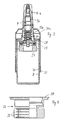
Eine Dosiervorrichtung nach Fig. 1 weist einen Verschlussdeckel 1 auf,
der auf einen Medienspeicher, vorzugsweise in Form eines flaschen-
oder dosenförmigen Behältnisses, aufrastbar ist. Hierzu ist der Verschlussdeckel
1 becherartig gestaltet und er weist an seinem Innenumfang
eine nicht näher bezeichnete Ringschulter auf, die auf einen korrespondierenden
Ringflansch in einem Halsbereich des Medienspeichers
aufrastbar ist. In einem oberen Bereich des Verschlussdeckels 1
ist eine nicht bezeichnete, umlaufende elastische Dichtung vorgesehen,
die beim Aufrasten des Verschlussdeckels 1 auf den Hals des Medienspeichers
komprimiert wird und so einen dichten Verschluss des
Medienspeichers gewährleistet. An den Verschlussdeckel 1 einstückig
angeformt ist ein becherartiger Aufnahmeteil 2, der entgegengesetzt zu
dem nicht dargestellten Medienspeicher koaxial zu einer Mittellängsachse
des Verschlussdeckels 1 nach oben abragt. Der Aufnahmeteil 2
bildet einen äußeren, mantelförmigen Gehäuseteil für eine nachfolgend
näher beschriebenen Pumpvorrichtung, die Teil der Dosiervorrichtung
nach Fig. 1 ist. Ebenfalls einstückig von dem Verschlussdeckel 1 abragend,
und zwar koaxial innerhalb des Aufnahmeteils 2 ist ein feststehender
Pumpgehäuseteil 3 vorgesehen, der koaxial zur Mittellängsachse
des Verschlussdeckels 1 mit einem Austragkanal 6 versehen ist,
der sowohl nach unten zum Medienspeicher hin als auch nach oben in
Richtung einer Dosieröffnung 18 hin offen ist. In einem unteren Abschnitt
des Austragkanals 6 ist ein grundsätzlich bekannter, vorzugsweise flexibler
Ansaugstutzen 7 eingesetzt. Ein oberer Abschnitt des Austragkanals
6 ist als Dosierstrecke 13 gestaltet, indem dieser obere Abschnitt
ausgehend von einer stufenförmigen Verjüngung des Austragkanals 6
einen zylindrischen Dosierkanal mit gegenüber dem unteren Abschnitt
des Austragkanals 6 verringerten Durchmesser darstellt. Die als Dosierkanal
gestaltete Dosierstrecke 13 ist von einem inneren Zylindermantel
4 umgeben. 1 has a
Radial in Abstand zu dem inneren Zylindermantel 4 bildet der innere
Pumpgehäuseteil 3 einen äußeren Zylindermantel 5, der - wie auch der
innere Zylindermantel 4 - einstückig an dem Verschlussdeckel 1 angeformt
ist. Der äußere Zylindermantel 5 ist koaxial zu dem inneren Zylindermantel
ausgerichtet. Zwischen dem inneren Zylindermantel 4 und
dem äußeren Zylindermantel 5 verbleibt ein ringförmiger Verdrängerraum
14, auf den nachfolgend noch näher eingegangen wird und der zu
einer Pumpkammer zählt.The inner one forms a radial distance from the inner cylinder jacket 4
Pump housing part 3 an outer cylinder jacket 5, which - like the
inner cylinder jacket 4 - integrally formed on the
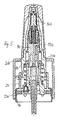
Relativ zu dem lagefest am Medienspeicher befestigbaren Aufnahmeteil
2 einschließlich des inneren Pumpgehäuseteils 3 ist eine Pumpeinheit
hubbeweglich gelagert. Die hubbewegliche Pumpeinheit weist einen
äußeren Pumpgehäuseteil 8 auf, der mit einer inneren Pumpkolbeneinheit
9 bis 11 fest verbunden ist. Die Pumpkolbeneinheit 9 bis 11 ist separat
als einstückiges Bauteil hergestellt und im Inneren des äußeren
Pumpgehäuseteiles 8 verrastet. Die Pumpkolbeneinheit weist einen
Kolbenkörper 9 auf, der in einem oberen Bereich einen Zylinderraum für
ein koaxial angeordnetes, hubbewegliches Auslassventil 16 bildet. Das
Auslassventil 16 ist durch eine Druckfederanordnung, vorliegend in
Form einer nicht näher bezeichneten Schraubendruckfeder, in Schließrichtung
so druckbelastet, dass das kolbenförmige Auslassventil 16 die
Auslassöffnung 18 verschließt. Die Druckfederanordnung ist im Inneren
des kolbenförmigen Auslassventils 16 angeordnet und stützt sich an
einem Boden des Zylinderraumes des Kolbenkörpers 9 ab. Der Zylinderraum
des Kolbenkörpers 9 ist in seinem oberen Randbereich mit einer
umlaufenden Dichtlippe versehen, die sich umlaufend dicht an den Außenmantel
des kolbenförmigen Auslassventils 16 anschmiegt. Dadurch
ist der Zylinderraum und damit auch der Aufnahmeraum für die Druckfederanordnung
gegen das Eindringen eines Mediums, insbesondere einer
Flüssigkeit, abgedichtet. Das Auslassventil 16 ist zusätzlich als Füllstück
ausgebildet, indem es das Innere des äußeren Pumpgehäuseteiles
8 nahezu vollständig ausfüllt. Auch der Kolbenkörper 9 ist als Füllkörper
gestaltet, indem er mit seiner Außenkontur weitgehend an die
Innenkontur des äußeren Pumpgehäuseteiles 8 angepasst ist.Relative to the receptacle part that can be securely attached to the
In dem Kolbenkörper 9 ist ein erster Abschnitt einer zur Pumpkammer
gehörenden Auslasskammer 17 gebildet, die zu dem Verdrängerraum
14 und der Dosierstrecke 13 hin offen ist. Dieser erste Abschnitt ist in
seinem oberen Bereich radial nach außen hin offen und geht in einen
Ringkammerabschnitt der Auslasskammer 17 über, der zwischen dem
Außenmantel des Kolbenkörpers 9, der Außenkontur des Auslassventils
16 und der Innenkontur des äußeren Pumpgehäuseteiles 8 gebildet ist.
Durch die Rastverbindung des Kolbenkörpers 9 in einem ringförmigen
Rastflanschbereich mit dem äußeren Pumpgehäuseteil 8 ist der Ringkammerabschnitt
axial nach unten geschlossen. Zur Auslassöffnung 18
hin verschließt das Auslassventil 16 den Ringkammerabschnitt der
Auslasskammer 17.In the piston body 9 there is a first section to the pump chamber
associated
In einem unteren Bereich bildet der Kolbenkörper 9 einen koaxial inneren
Ventilkolben 10, der zusammen mit dem inneren Zylindermantel 4
im Bereich der Dosierstrecke 13 ein als Schieberventil gestaltetes Einlassventil
für die Pumpvorrichtung bildet. Hierzu ist der Ventilkolben 10,
der einstückig an dem Kolbenkörper 9 angeformt ist, in einem unteren
Bereich mit einer ringförmigen Dosierlippe 12 versehen, die sich bei einem
Eintauchen des Ventilkolbens 10 in die Dosierstrecke 13 dicht an
eine Innenwandung des die Dosierstrecke 13 bildenden Dosierkanals
anschmiegt. Der Durchmesser der Dosierlippe 12 ist größer als der
Durchmesser des Ventilkolbens 10. Die Länge des Ventilkolbens 10 sowie
der Hub des Kolbenkörpers 9 und damit der gesamten, hubbeweglichen
Pumpeinheit sind so bemessen, dass die Dosierlippe 12 in einer
oberen, in Fig. 1 dargestellten Öffnungsstellung im geringen Abstand
oberhalb der Dosierstrecke 13 positioniert ist. In einer unteren, vollständig
nach unten gedrückten Endposition der hubbeweglichen Pumpeinheit
ist die Dosierlippe 12 in die stufenförmige Erweiterung des Austragkanals
6 hineingefahren, d.h. sie ist über die Dosierstrecke 13 hinaus
nach unten bewegt worden. Da der Außendurchmesser der Dosierlippe
12 geringer ist als der Durchmesser des Austragkanals 6 in den stufenförmig
erweiterten Bereich und darüber hinaus der Durchmesser des
Ventilkolbens 10 geringer ist als der Innendurchmesser der Dosierstrecke
13, kann in dieser unteren Endposition der Pumpeinheit ein Mediumaustausch
zwischen der Auslasskammer 17 und dem Medienspeicher
- über den Ansaugstutzen 7 - erfolgen.In a lower region, the piston body 9 forms a coaxially inner one
Koaxial und in radialem Abstand ist der Ventilkolben 10 von einem glockenartigen
Verdrängerkolben 11 umschlossen, der mittels eines unteren
Dichtrandes umlaufend dicht an einer Innenwandung des ringförmigen
Verdrängerraumes 14 anliegt. Der Querschnitt des glockenförmigen
Verdrängerkolbens 11 ist an den Querschnitt des Verdrängerraumes
14 derart angepasst, dass in der nach unten bewegten Endposition
des Kolbenkörpers nahezu kein Totraum im Verdrängerraum verbleibt,
da der Verdrängerkolben 11 in dieser Position vollständig in den
Verdrängerraum 14 eingetaucht ist. Auch der zwischen der Außenwandung
des Ventilkolbens 10 und der Innenwandung des Verdrängerkolbens
11 verbleibende Ringraum ist in seinem Volumen auf das Körpervolumen
des inneren Zylindermantels 4 abgestimmt, wodurch das
verbleibende Totraumvolumen bei nach unten bewegter Pumpeinheit
weiter reduziert ist. Das kolbenförmige Auslassventil 16 ist im Bereich
seines Außenmantels mit mehreren Ringstufen versehen, die Druckangriffsflächen
zum Öffnen des Auslassventils 16 bilden. Die Schutzkappe
19 weist eine sich konisch nach unten erweiternde Glockenform auf, die
über einen oberen Formabschnitt des äußeren Pumpgehäuseteiles 8
gestülpt ist und auf einem Ringschulterabsatz des Pumpgehäuseteiles 8
axial zur Anlage kommt. Die Schutzkappe 19 wird manuell lösbar auf
den Formabschnitt des Pumpgehäuseteiles 8 aufgerastet. Der Außendurchmesser
der Schutzkappe 19 ist geringer als der maximale Außendurchmesser
des Pumpgehäuseteils 8. Der obere Formabschnitt des
Pumpgehäuseteils 8 ist als Nasenolive gestaltet, um eine Applikation eines
in dem Medienspeicher enthaltenen Mediums in die Nase zu ermöglichen.
Vorzugsweise ist in dem in dem Medienspeicher gelagerten
Medium wenigstens ein pharmazeutischer Wirkstoff enthalten.The
Auf einen Außenmantelbereich des äußeren Pumpgehäuseteiles 8 ist
eine Betätigungshandhabe 20 aufgerastet, die an ihrer Oberseite wenigstens
auf zwei gegenüberliegenden Seiten mit jeweils einer Fingerauflage
versehen ist. In der Darstellung gemäß Fig. 1 sind die Fingerauflagen
mit Profilierungen versehen. Zur Axialsicherung der Betätigungshandhabe
20 ist am Außenumfang des Pumpgehäuseteiles 8 ein
umlaufender Raststeg 21 vorgesehen, dem oberhalb wenigstens eine
Rastnut zugeordnet ist, in die entsprechende Innenrandabschnitte der
Betätigungshandhabe 20 axial einrasten. Vorzugsweise wird die Betätigungshandhabe
20 auf dem Pumpgehäuseteil 8 mittels einer unlösbaren
Rastverbindung aufgerastet, d.h. nach dem axialen Aufrasten der Betätigungshandhabe
20 ist diese von dem Pumpgehäuseteil 8 nicht mehr
entfernbar, ohne zerstört zu werden.On an outer jacket area of the outer pump housing part 8
an
Unterhalb des Raststeges 21 weist der Pumpgehäuseteil 8 einen zylindrischen
Führungsmantel auf, der in seinem unteren Randbereich mit
mehreren, über den Außenumfang des Führungsmantels auf gleicher
Höhe verteilt angeordneten Anschlagnocken 23 versehen ist, die mit einem
radial nach innen abragenden, umlaufenden Rastbund 24 des mantel-
oder becherartigen Aufnahmeteiles 2 zusammenwirken. Die Rastnocken
23 und der Rastbund 24 bilden Rastprofilierungen, die eine Axialsicherung
des hubbeweglichen Pumpgehäuseteils 8 an dem feststehenden
Aufnahmeteil 2 gewährleisten. Die Rastprofilierungen 23, 24
bilden einen axialen Rückhalt des Pumpgehäuseteils 8 gegen die
Druckkraft einer Pumpfederanordnung 15, die als Pumpantrieb für eine
Rückstellung der hubbeweglichen Pumpeinheit in die in Fig. 1 dargestellte
Ausgangslage dient. Ein manuelles Nachuntendrücken der
Pumpeinheit erfolgt somit gegen die Druckkraft der Pumpfederanordnung
15. Wie anhand der Fig. 1 erkennbar ist, ist die Pumpfederanordnung
15 außerhalb des äußeren Zylindermantels 5 des inneren, feststehenden
Pumpgehäuseteils 8 angeordnet, so dass die Pumpfederanordnung
15 außerhalb des von Medium durchströmten Pumpraumes positioniert
ist. Die Pumpfederanordnung 15 kann somit mit dem Medium,
beispielsweise einer wenigstens einen pharmazeutischen Wirkstoff enthaltenden
Flüssigkeit, nicht in Verbindung geraten.Below the locking
Die Betätigungshandhabe 20 weist einen ringförmigen Sicherungsfortsatz
22 auf, der als Zylindermantel nach unten abragt und in der in Fig. 1
dargestellten, oberen Endposition der Pumpeinheit den Aufnahmeteil 2
so weit axial überragt, dass er den Bereich der Rastprofilierungen 23, 24
überlappt. Der Abstand der Außenseite des Aufnahmeteils zur Innenwandung
des Schutzfortsatzes 22 ist vorzugsweise geringer als die radiale
Erstreckung der Rastprofilierungen 23, 24, so dass der starre, ringförmige
Schutzfortsatz 22 einen Schutz gegen ein Lösen der Rastprofilierungen
23, 24 und damit eine Abzugsicherung für den Pumpgehäuseteil
8 bildet.The actuating handle 20 has an
Da der Verschlussdeckel 1 in Verbindung mit der zuvor beschriebenen
Pumpvorrichtung ein als Medienspeicher dienendes Behältnis dicht abschließt,
muss bei entsprechenden Pumpvorgängen ein Druckausgleich
erfolgen, um die Funktion der Pumpvorrichtung nicht zu beeinträchtigen.
Beim dargestellten Ausführungsbeispiel ist hierzu eine Druckausgleichsvorrichtung
25, 26, D vorgesehen, die in dem Verschlussdeckel 1
integriert ist. Die Druckausgleichsvorrichtung weist zum einen eine sich
zur Außenseite hin stark verjüngende, als Druckausgleichsöffnung dienende
Düsenbohrung D auf, deren engster Durchmesser vorzugsweise
0,2mm bis 0,3mm nicht übersteigt. Hierdurch wird ein Gasaustausch
gewährleistet, ein Flüssigkeitsverlust hingegen ist aufgrund der äußerst
kleinen Düsenbohrung D minimiert. Damit ergibt sich eine reduzierte
Verdunstung. Die reduzierte Verdunstung ist insbesondere vorteilhaft für
die in Fig. 1 zusätzlich vorgesehene Filteranordnung 25. Die Filteranordnung
25 weist ein nicht näher bezeichnetes Aufnahmegehäuse für
einen membranförmigen Filter 26 auf. Das Aufnahmegehäuse ist in eine
korrespondierende Aufnahme des Verschlussdeckels 1 eingesetzt und
vorzugsweise in diese eingeklebt oder in anderer Art und Weise fest mit
dieser verbunden. Der membranförmige Filter 26 ist bei der dargestellten
Ausführungsform von dem Aufnahmegehäuse umspritzt und somit in
diesem integriert. Alternativ ist es auch möglich, den membranförmigen
Filter 26 auf einen oberen Stirnrand des Aufnahmegehäuses aufzulaminieren.
Der membranförmige Filter stellt vorzugsweise eine PP/PTFE-Membran
oder eine TPE/PES-Membran dar. Der Filter 26 dient dazu,
eine Kontaminierung des in dem Medienspeicher befindlichen Mediums
zu vermeiden, indem die durch die Düsenbohrung D bei einem entsprechenden
Pumpvorgang als Druckausgleich angesaugte Atmosphärenluft
durch die entsprechende Membran gereinigt wird. Ein Wasser- oder
Feuchtigkeitseintritt wird durch die Filteranordnung 25 vermieden.Since the
Nachfolgend wird die Funktion der in Fig. 1 dargestellten Dosiervorrichtung
beschrieben. Das durch den Ventilkolben 10 in Verbindung mit der
Dosierlippe 12 und der Dosierstrecke 13 gebildete Einlassventil arbeitet
bei einem manuellen Betätigen der Betätigungshandhabe 20 als Schieber,
indem der äußere Pumpgehäuseteil 8 zusammen mit der Pumpeinheit
9 bis 11 nach unten bewegt wird. Durch die Tatsache, dass die Dosierlippe
12 bei einem kompletten Hub der Pumpeinheit nach unten unterhalb
der Dosierstrecke 13 und damit unterhalb des stufenförmigen
Absatzes im Austragkanal 6 ins Freie läuft, wird ein sogenanntes Priming
ermöglicht. Das bedeutet, dass in dem durch die Auslasskammer
17, dem Verdrängerraum 14 und dem Ringraum zwischen dem inneren
Ventilkolben 10 und dem äußeren Verdrängerkolben 11 definierten
Pumpraum der Pumpvorrichtung befindliche Luft bei einer Hubbewegung
der Pumpeinheit nach unten in den Austragkanal 6 und damit in
den Ansaugstutzen 7 und in den Medienspeicher entweichen kann.
Beim anschließenden Rückhub erfolgt die entsprechende Ansaugung
des flüssigen Mediums. Aufgrund des äußerst geringen Totraumvolumens
innerhalb des als Pumpkammer dienenden Pumpraumes der
Pumpvorrichtung genügt vorzugsweise bereits ein einziger Hub als Priming,
um eine ausreichende Ansaugung des auszubringenden Mediums
in der Pumpkammer zu erzielen. Die Länge des Hubs der Dosierlippe 12
entlang der Dosierstrecke 13 definiert das Dosiervolumen. Die definierte,
und vom übrigen Austragkanal 6 verjüngt abgestufte Dosierstrecke 13 in
Verbindung mit dem als Schieber nach unten ins Freie laufenden Ventilkolben
10 ermöglicht auch nach dem Abschluss des Primings, d.h. nach
der vollständigen Befüllung des gesamten Mediumweges im Austragkanal
6 sowie in der Pump- oder Dosierkammer der Pumpvorrichtung eine
besonders exakte und zuverlässige Dosierung.The following is the function of the metering device shown in FIG. 1
described. That by the
Ein Austragvorgang erfolgt, sobald der Flüssigkeitsdruck in der Pumpkammer,
d.h. insbesondere im oberen Bereich der Auslasskammer 17,
der auf das kolbenförmige Auslassventil 16 wirkt, den durch die Druckfederanordnung
aufgebrachten Gegendruck übersteigt. Der Flüssigkeitsdruck
drückt dann das Auslassventil 16 gegen die Druckkraft der
Druckfederanordnung nach unten, wodurch über die Auslassöffnung 18
der entsprechende Austragvorgang des Mediums erfolgt. Die Auslassöffnung
18 ist vorzugsweise düsenförmig gestaltet, um eine Zerstäubung
des ausgebrachten Mediums zu bewirken. Selbstverständlich wird vor
einem entsprechenden Austragvorgang die Schutzkappe 19 entfernt.A discharge process takes place as soon as the liquid pressure in the pump chamber,
i.e. especially in the upper area of the
Die in Fig. 1 dargestellte Dosiervorrichtung besteht aus wenigen Kunststoffbauteilen,
vorliegend aus insgesamt lediglich sechs Kunststoffbauteilen.
Ein erstes Kunststoffbauteil stellt der Verschlussdeckel 1 in Verbindung
mit dem Aufnahmeteil 2 und dem inneren Pumpgehäuseteil 3
dar. Das zweite Kunststoffbauteil wird durch den äußeren Pumpgehäuseteil
8 gebildet. Das dritte Kunststoffbauteil ist die Pumpkolbeneinheit 9
bis 11. Das vierte Kunststoffbauteil ist das kolbenförmige Auslassventil
16. Das fünfte Kunststoffbauteil ist die mit den Fingerauflagen versehene
Betätigungshandhabe 20 und das letzte Kunststoffbauteil ist die
Schutzkappe 19. Zur Montage der Dosiervorrichtung wird zunächst das
kolbenförmige Auslassventil 16 gemeinsam mit der dieses beaufschlagenden
Druckfederanordnung in die Pumpkolbeneinheit 9 eingesetzt
und anschließend die Pumpkolbeneinheit 9 gemeinsam mit dem Auslassventil
16 ins Innere des äußeren Pumpgehäuseteiles 8 eingerastet,
wodurch eine obere Stirnfläche des Auslassventils 16 gegen den korrespondierenden
Ventilsitz im Bereich der Auslassöffnung 18 gepresst
wird. Anschließend wird der äußere Pumpgehäuseteil 8 zusammen mit
der Pumpkolbeneinheit 9 bis 11 in das feststehende Kunststoffbauteil
axial eingeschoben, wodurch die Verrastung und axiale Sicherung im
Bereich der Rastprofilierungen 23, 24 erfolgt. Nun wird die Betätigungshandhabe
20 axial von oben her auf den äußeren Pumpgehäuseteil 8
aufgerastet, wodurch die Rastverbindung und Axialsicherung zwischen
Pumpgehäuseteil 8 und Aufnahmeteil 2 des Verschlussdeckels 1 überdeckt
und gesichert ist. In den Verschlussdeckel 1 wird die Filteranordnung
25 wie auch die umlaufende Dichtung eingesetzt. Anschließend
kann der Verschlussdeckel 1 auf einen entsprechenden Medienspeicher
dicht aufgesetzt werden. Vor dem axialen Aufsetzen des äußeren
Pumpgehäuseteils 8 auf den Verschlussdeckel 1 wurde die Pumpfederanordnung
15 eingefügt.The dosing device shown in Fig. 1 consists of a few plastic components,
in the present case from a total of only six plastic components.
The
Bei der Ausführungsform nach den Fig. 2 bis 4 entspricht eine Pumpvorrichtung
P der zuvor anhand der Fig. 1 beschriebenen Pumpvorrichtung,
so dass für eine nähere Erläuterung der Pumpvorrichtung P auf
die ausführliche Beschreibung zur Fig. 1 verwiesen wird. Funktionsgleiche
Teile sind mit gleichem Bezugszeichen gegenüber der Ausführungsform
nach Fig. 1, jedoch unter Hinzufügung des Buchstabens "a",
versehen. Nachfolgend wird lediglich auf die Unterschiede der Pumpvorrichtung
P zu der Pumpvorrichtung in Fig. 1 eingegangen. Zudem wird
die übrige Dosiervorrichtung, in der die Pumpvorrichtung P integriert
ist, beschrieben. Wesentlicher Unterschied zu der Ausführungsform
nach Fig. 1 ist es, dass die Pumpvorrichtung P als separate Baueinheit
getrennt von der Dosiervorrichtung herstellbar und lösbar mit dieser
verbunden ist. Bei der Ausführungsform nach den Fig. 2 bis 4 ist der
Aufnahmeteil 2a zwar ebenfalls einstückig mit dem inneren Pumpgehäuseteil
gestaltet. Der innere Pumpgehäuseteil, der von der Pumpfederanordnung
15a umgeben ist, stellt jedoch gemeinsam mit dem Aufnahmeteil
2a eine von einem Verschlussdeckel 28 für einen Behälterbecher
B getrennte Einheit dar. Der Verschlussdeckel 28 ist hülsen- oder
ringartig gestaltet und weist eine Aufnahmevertiefung auf, in die der
Aufnahmeteil 2a der Pumpvorrichtung P mittels eines umlaufenden
Ringflansches einrastbar ist. Hierzu ist ein Rand der Aufnahmevertiefung
mit einer ringförmigen Raststelle versehen, die in den Fig. 2 und 3
erkennbar, jedoch nicht näher bezeichnet ist. Ein dichter und spielfreier
Sitz des Ringflansches und damit des Aufnahmeteils 2a in der Aufnahmevertiefung
des Verschlussdeckels 28 wird durch eine Ringdichtung
29 gewährleistet, die unterhalb des Ringflansches positioniert ist und
auf einem Tellerrand der ringförmigen Aufnahmevertiefung des Verschlussdeckels
28 aufliegt. Der Verschlussdeckel 28 ist als Kunststoffteil
gestaltet und mit einem oberen Randbereich des Behälterbechers B°
verrastet oder durch Krimpen fest mit diesem verbunden.In the embodiment according to FIGS. 2 to 4, a pump device corresponds
P of the pump device previously described with reference to FIG. 1,
so that for a more detailed explanation of the pump device P on
the detailed description of Fig. 1 is referenced. functionally identical
Parts have the same reference numerals compared to the
Der Verschlussdeckel 28 ist unterhalb des Tellerrandes der Aufnahmevertiefung
mit einem einstückig angeformten Profilring 27 versehen, der
als Fortsatz zu dem Verschlussdeckel 28 in das Innere des Behälterbechers
B hineinragt. Wie anhand der Fig. 4 erkennbar ist, ist der Profilring
mit mehreren parallel und in Abstand zueinander angeordneten Ringrippen
32 versehen, die radial zu einer Mittellängsachse des Verschlussdeckels
28 nach außen abragen. Zudem sind mehrere, über die
Höhe des Profilringes 27 erstreckte, vertikal ausgerichtete Rippenstege
vorgesehen, die in den Fig. 2 bis 4 nicht näher bezeichnet sind. Diese
Rippenstege sind über den Umfang des Profilringes 27 verteilt angeordnet.
Die Schnittdarstellung in den Fig. 2 und 3 ist jeweils durch zwei solche
Rippenstege hindurchgezogen.The
Eine Betätigungshandhabe 20a für die Pumpvorrichtung P entspricht
bezüglich ihrer Pumpbetätigungsfunktion der Betätigungshandhabe 20
nach Fig. 1. Die Betätigungshandhabe 20a ist zusätzlich als becherförmiger
Zylindermantel gestaltet, der den Behälterbecher B über mehr als
die Hälfte seiner Höhe axial übergreift. Der Außenmantel des Behälterbechers
B und eine Innenwandung eines unteren Randbereiches des
Zylindermantels 22a der Betätigungshandhabe 20a sind mit korrespondierenden
Anschlagprofilierungen 30, 31 versehen, die einander in axialer
Richtung formschlüssig hintergreifen. Hierdurch wird für die Betätigungshandhabe
20a eine Axialsicherung gewährleistet. Da die Betätigungshandhabe
20a - wie die Betätigungshandhabe 20 nach Fig. 1 -
auf den äußeren Pumpgehäuseteil der Pumpvorrichtung P aufgerastet
ist, wird durch die Anschlagprofilierungen 30 und 31 gleichzeitig die
Hubbegrenzung der Pumpvorrichtung P geschaffen, die die notwendige
Rückhaltekraft gegen die Druckkraft der Pumpfederanordnung 15 bietet.An
Die Ausführungsform der Fig. 2 und die Darstellung in Fig. 3 sind geringfügig
modifiziert. So ist bei der Ausführungsform nach Fig. 3 in dem
Aufnahmeteil 2a der Pumpvorrichtung P eine Aufnahme für den Einsatz
einer Filteranordnung vorgesehen, wie sie aus Fig. 1 ersichtlich ist.
Falls der Verschlussdeckel 28 daher einen dichten Abschluss des Behälterbechers
B bietet, kann der Behälterbecher B direkt als Medienspeicher
für eine entsprechende Flüssigkeit dienen, da trotz des formstabilen
Behälterbechers B durch die mit der Düsenbohrung versehene
Aufnahme, gegebenenfalls mit zusätzlichem Einsatz einer Filteranordnung,
ein ausreichender Druckausgleich während des Betriebs der
Pumpvorrichtung P gegeben ist. The embodiment of FIG. 2 and the illustration in FIG. 3 are minor
modified. So in the embodiment of FIG. 3 in the
Bei der Darstellung nach Fig. 2 hingegen ist eine derartige Druckausgleichsvorrichtung
für den Behälterbecher B nicht gegeben. Stattdessen
ist in dem Behälterbecher B ein Medienspeicher S mit flexibler Wandung
vorgesehen. Vorliegend ist der Medienspeicher S als aus einer
ein- oder mehrlagigen Folie hergestellter Folienbeutel gestaltet, der umlaufend
dicht mit dem Profilring 27 verbunden ist. Vorzugsweise ist der
Folienbeutel mit dem Profilring 27 verschweißt, wobei die Profilierungen
des Profilringes 27 die Oberfläche für eine dichte Verschweißung des
Folienbeutels mit dem Profilring 27 vergrößern. Hierdurch ist eine große
Sicherheit der Schweißverbindung wie auch des dichten Abschlusses
des Folienbeutels mit dem Profilring 27 gewährleistet. Der als Medienspeicher
S dienende Folienbeutel ist somit lediglich zur Pumpvorrichtung
P hin offen, wodurch die gleiche Pump- und Austragfunktion erzielbar
ist wie bei der Ausführungsform nach Fig. 1. Mit jedem Austragvorgang
verringert sich das Volumen des Medienspeichers S, wodurch der Folienbeutel
sich zusammenzieht. Die flexible Wandung des Folienbeutels
ermöglicht somit den Druck- und Volumenausgleich innerhalb des Medienspeichers
S bei entsprechenden Austragsvorgängen der Pumpvorrichtung
P.2, however, is such a pressure compensation device
not given for container cup B. Instead
is a media storage S with flexible wall in the container cup B.
intended. In the present case, the media store S is made up of one
single or multi-layer film made of foil bags, the circumferential
is tightly connected to the
Bei der Ausführungsform nach den Fig. 5 und 6 ist eine Dosiervorrichtung
dargestellt, deren Pumpvorrichtung mit der Pumpvorrichtung nach
Fig. 1 übereinstimmt. Funktionsgleiche Teile der Dosiervorrichtung sind
mit den gleichen Bezugszeichen versehen wie bei der Ausführungsform
nach Fig. 1, jedoch unter Hinzufügung des Buchstabens "b". Bezüglich
einer näheren Erläuterung wird auf die Beschreibung zur Fig. 1
verwiesen. Nachfolgend wird lediglich auf die in den Fig. 5 und 6 dargestellten
Unterschiede ausführlich eingegangen. Wesentlicher Unterschied
ist es, dass der Aufnahmeteil 2b ähnlich wie bei der Ausführungsform
nach Fig. 2 bis 4 separat zu einem Verschlussdeckel 1b
gestaltet ist. Der Verschlussdeckel 1b ist als Krimpdeckel ausgeführt,
der auf einen korrespondierenden Behälterhals eines Medienspeichers
aufsetzbar ist. Das Aufsetzen des Aufnahmeteiles 2b gemeinsam mit
dem als Krimpdeckel gestalteten Verschlussdeckel 1b erfolgt unter Zwischenfügung
einer nicht näher bezeichneten, umlaufenden elastischen
Dichtung. Die Betätigungshandhabe 20b weist einen becherförmigen
Schutzfortsatz 22b auf, der bis über den als Krimpdeckel ausgeführten
Verschlussdeckel 1b nach unten gezogen ist, so dass der Schutzfortsatz
22b einem Krimpbereich des als Krimpdeckel gestalteten Verschlussdeckels
1b axial überdeckt. Dadurch wird ein Lösen des Verschlussdeckels
1b von einem entsprechenden Behälterhals eines Medienspeichers
vermieden, sobald die Betätigungshandhabe 20b auf den äußeren
Pumpgehäuseteil 8b der Pumpvorrichtung gemäß der Darstellung und
Beschreibung nach Fig. 1 aufgerastet ist. Da der Schutzfortsatz den
Krimpbereich des Verschlussdeckels 1b überdeckt, wird die separat
hergestellte Betätigungshandhabe erst dann auf dem Pumpgehäuseteil
8b montiert, wenn der Verschlussdeckel 1b auf einen entsprechenden
Behälterhals eines Medienspeichers aufgekrimpt ist. Denn mit bereits
aufgerasteter Betätigungshandhabe 22b wäre kein Krimpvorgang mehr
möglich.5 and 6 is a metering device
shown, the pumping device with the pumping device after
Fig. 1 matches. Functionally identical parts of the dosing device are
provided with the same reference numerals as in the
Claims (7)
Priority Applications (9)
| Application Number | Priority Date | Filing Date | Title |
|---|---|---|---|
| DE20212898U DE20212898U1 (en) | 2002-04-20 | 2002-08-20 | Dispensing device, includes pump with sliding valve for removing liquid from reservoir |
| PL367350A PL200833B1 (en) | 2001-09-21 | 2002-09-17 | Dosing device comprising a medium reservoir and corresponding pump device |
| PCT/EP2002/010421 WO2003026805A1 (en) | 2001-09-21 | 2002-09-17 | Dosing device comprising a medium reservoir and corresponding pump device |
| BRPI0212901-9A BR0212901B1 (en) | 2001-09-21 | 2002-09-17 | metering device with a medium reservoir as well as pump device for a metering device. |
| CA2460534A CA2460534C (en) | 2001-09-21 | 2002-09-17 | Dosing device comprising a medium reservoir and corresponding pump device |
| US10/490,573 US7182226B2 (en) | 2001-09-21 | 2002-09-17 | Dosing device comprising a medium reservoir and corresponding pump device |
| JP2003530432A JP4210215B2 (en) | 2001-09-21 | 2002-09-17 | Dosing device with medium reservoir and pump device therefor |
| CNB02823152XA CN1283365C (en) | 2001-09-21 | 2002-09-17 | Dosing device comprising a medium reservoir and corresponding pump device |
| ARP020103528A AR036555A1 (en) | 2001-09-21 | 2002-09-19 | DOSING DEVICE WITH FLUID CONTAINER AS ALSO PUMP DEVICE |
Applications Claiming Priority (2)
| Application Number | Priority Date | Filing Date | Title |
|---|---|---|---|
| DE10148899 | 2001-09-21 | ||
| DE10148899 | 2001-09-21 |
Publications (2)
| Publication Number | Publication Date |
|---|---|
| EP1295646A1 true EP1295646A1 (en) | 2003-03-26 |
| EP1295646B1 EP1295646B1 (en) | 2006-12-20 |
Family
ID=7701333
Family Applications (3)
| Application Number | Title | Priority Date | Filing Date |
|---|---|---|---|
| EP02008877A Expired - Lifetime EP1295645B1 (en) | 2001-09-21 | 2002-04-20 | Metering device provided with a pump |
| EP02008878A Expired - Lifetime EP1295646B1 (en) | 2001-09-21 | 2002-04-20 | Dosing device with a fluid container and pump therefor |
| EP02008876A Expired - Lifetime EP1295644B1 (en) | 2001-09-21 | 2002-04-20 | Dosing device with a reservoir and a pump |
Family Applications Before (1)
| Application Number | Title | Priority Date | Filing Date |
|---|---|---|---|
| EP02008877A Expired - Lifetime EP1295645B1 (en) | 2001-09-21 | 2002-04-20 | Metering device provided with a pump |
Family Applications After (1)
| Application Number | Title | Priority Date | Filing Date |
|---|---|---|---|
| EP02008876A Expired - Lifetime EP1295644B1 (en) | 2001-09-21 | 2002-04-20 | Dosing device with a reservoir and a pump |
Country Status (5)
| Country | Link |
|---|---|
| EP (3) | EP1295645B1 (en) |
| AR (3) | AR036555A1 (en) |
| AT (3) | ATE348664T1 (en) |
| DE (3) | DE50213095D1 (en) |
| ES (2) | ES2276868T3 (en) |
Cited By (7)
| Publication number | Priority date | Publication date | Assignee | Title |
|---|---|---|---|---|
| WO2007096049A2 (en) | 2006-02-21 | 2007-08-30 | Ing. Erich Pfeiffer Gmbh | Dosing device with a manually actuated pumping means |
| EP1547694A3 (en) * | 2003-12-24 | 2008-05-14 | Expac Corporation | Fluid dispenser assembly |
| US8016165B2 (en) * | 2004-06-16 | 2011-09-13 | Valois Sas | Fluid product dispensing device |
| EP2314380A3 (en) * | 2009-10-23 | 2011-12-14 | Ing. Erich Pfeiffer GmbH | Dispenser |
| DE102013215599A1 (en) | 2013-08-07 | 2015-02-12 | Aptar Radolfzell Gmbh | Pumping device and dispenser for liquid or pasty media |
| EP3508280A1 (en) | 2018-01-09 | 2019-07-10 | Aero Pump GmbH | Application device for applying liquid media |
| EP3491345B1 (en) | 2016-07-14 | 2021-08-04 | F. Holzer GmbH | Pump head and dosing device |
Families Citing this family (7)
| Publication number | Priority date | Publication date | Assignee | Title |
|---|---|---|---|---|
| DE102004044344A1 (en) * | 2004-09-09 | 2006-03-30 | Ing. Erich Pfeiffer Gmbh | metering |
| DE102004050679A1 (en) * | 2004-10-13 | 2006-04-20 | Ing. Erich Pfeiffer Gmbh | metering |
| US7914497B2 (en) | 2005-01-26 | 2011-03-29 | Radius International Limited Partnership | Catheter |
| FR2903329B3 (en) | 2006-07-10 | 2008-10-03 | Rexam Dispensing Systems Sas | SPRAY NOZZLE, SPRAY DEVICE AND USE THEREOF. |
| DE102008027599A1 (en) * | 2008-06-10 | 2009-12-31 | Meadwestvaco Calmar Gmbh | Fluidaustragkopf |
| DE102009040783B4 (en) * | 2009-09-09 | 2012-04-26 | F. Holzer Gmbh | Metering device for metered dispensing of liquid preparations, method for filling and use of a metering device according to the invention |
| EP3427839B1 (en) | 2017-07-13 | 2020-12-02 | Aptar Radolfzell GmbH | Liquid dispenser with ventilated bottle and applicator head for same |
Citations (6)
| Publication number | Priority date | Publication date | Assignee | Title |
|---|---|---|---|---|
| EP0000313A1 (en) * | 1977-07-01 | 1979-01-10 | Norbert Normos | Pressure accumulative spraying pump and spray head |
| US4369900A (en) * | 1979-05-16 | 1983-01-25 | Yoshino Kogyosho Co., Ltd. | Manual accumulator type atomizer |
| US4371097A (en) * | 1980-05-07 | 1983-02-01 | Diamond International Corporation | Liquid dispensing pump |
| DE3315334A1 (en) | 1983-04-28 | 1984-10-31 | Pfeiffer Erich Gmbh & Co Kg | SPRAYER OR DOSING PUMP |
| US5351863A (en) * | 1993-03-08 | 1994-10-04 | Dupont Industries, Inc. | Manually-operated dispensing pump |
| US6050457A (en) * | 1995-12-06 | 2000-04-18 | The Procter & Gamble Company | High pressure manually-actuated spray pump |
Family Cites Families (6)
| Publication number | Priority date | Publication date | Assignee | Title |
|---|---|---|---|---|
| US4174055A (en) * | 1977-04-20 | 1979-11-13 | James D. Pauls & J. Claybrook Lewis & Associates, Ltd. | Non-aerosol pressure dispenser |
| DE3339180C2 (en) | 1983-10-28 | 1993-10-14 | Pfeiffer Erich Gmbh & Co Kg | Discharge device for media |
| FR2718372B1 (en) * | 1994-04-08 | 1996-06-28 | Sofab | Dispenser for fluid products. |
| DE29717240U1 (en) * | 1997-09-26 | 1997-11-27 | Gaplast Gmbh | Container with a pump |
| US6276568B1 (en) * | 1998-08-21 | 2001-08-21 | Pharmacia & Upjohn Company | Spray bottle grip |
| DE19940713A1 (en) * | 1999-02-23 | 2001-03-01 | Boehringer Ingelheim Int | Diffusion resistant cartridge for storing and dosing liquids, especially for producing drug-containing inhalable aerosols, has three-shell structure with collapsible bag, container and rigid housing |
-
2002
- 2002-04-20 AT AT02008878T patent/ATE348664T1/en not_active IP Right Cessation
- 2002-04-20 DE DE50213095T patent/DE50213095D1/en not_active Expired - Lifetime
- 2002-04-20 ES ES02008878T patent/ES2276868T3/en not_active Expired - Lifetime
- 2002-04-20 EP EP02008877A patent/EP1295645B1/en not_active Expired - Lifetime
- 2002-04-20 ES ES02008876T patent/ES2317962T3/en not_active Expired - Lifetime
- 2002-04-20 DE DE50208993T patent/DE50208993D1/en not_active Expired - Lifetime
- 2002-04-20 DE DE50212754T patent/DE50212754D1/en not_active Expired - Lifetime
- 2002-04-20 EP EP02008878A patent/EP1295646B1/en not_active Expired - Lifetime
- 2002-04-20 AT AT02008877T patent/ATE407745T1/en not_active IP Right Cessation
- 2002-04-20 EP EP02008876A patent/EP1295644B1/en not_active Expired - Lifetime
- 2002-04-20 AT AT02008876T patent/ATE416848T1/en not_active IP Right Cessation
- 2002-09-19 AR ARP020103528A patent/AR036555A1/en active IP Right Grant
- 2002-09-19 AR ARP020103530A patent/AR036557A1/en not_active Application Discontinuation
- 2002-09-19 AR ARP020103529A patent/AR036556A1/en active IP Right Grant
Patent Citations (6)
| Publication number | Priority date | Publication date | Assignee | Title |
|---|---|---|---|---|
| EP0000313A1 (en) * | 1977-07-01 | 1979-01-10 | Norbert Normos | Pressure accumulative spraying pump and spray head |
| US4369900A (en) * | 1979-05-16 | 1983-01-25 | Yoshino Kogyosho Co., Ltd. | Manual accumulator type atomizer |
| US4371097A (en) * | 1980-05-07 | 1983-02-01 | Diamond International Corporation | Liquid dispensing pump |
| DE3315334A1 (en) | 1983-04-28 | 1984-10-31 | Pfeiffer Erich Gmbh & Co Kg | SPRAYER OR DOSING PUMP |
| US5351863A (en) * | 1993-03-08 | 1994-10-04 | Dupont Industries, Inc. | Manually-operated dispensing pump |
| US6050457A (en) * | 1995-12-06 | 2000-04-18 | The Procter & Gamble Company | High pressure manually-actuated spray pump |
Cited By (17)
| Publication number | Priority date | Publication date | Assignee | Title |
|---|---|---|---|---|
| EP1547694A3 (en) * | 2003-12-24 | 2008-05-14 | Expac Corporation | Fluid dispenser assembly |
| US8016165B2 (en) * | 2004-06-16 | 2011-09-13 | Valois Sas | Fluid product dispensing device |
| US8382010B2 (en) | 2006-02-21 | 2013-02-26 | Aptar Radolfzell Gmbh | Dosing device with a manually actuatable pumping means |
| WO2007096049A2 (en) | 2006-02-21 | 2007-08-30 | Ing. Erich Pfeiffer Gmbh | Dosing device with a manually actuated pumping means |
| DE102006008874A1 (en) * | 2006-02-21 | 2007-09-13 | Ing. Erich Pfeiffer Gmbh | Metering device with a manually operable pumping device |
| WO2007096049A3 (en) * | 2006-02-21 | 2007-11-15 | Pfeiffer Erich Gmbh & Co Kg | Dosing device with a manually actuated pumping means |
| DE102006008874B4 (en) * | 2006-02-21 | 2012-06-21 | Ing. Erich Pfeiffer Gmbh | Metering device with a manually operable pumping device |
| CN101384373B (en) * | 2006-02-21 | 2012-07-04 | 艾里希普费弗工程师有限公司 | Dosing device with a manually actuable pumping means |
| US9700907B2 (en) | 2009-10-23 | 2017-07-11 | Aptar Radolfzell Gmbh | Discharging device |
| EP2314380A3 (en) * | 2009-10-23 | 2011-12-14 | Ing. Erich Pfeiffer GmbH | Dispenser |
| DE102013215599A1 (en) | 2013-08-07 | 2015-02-12 | Aptar Radolfzell Gmbh | Pumping device and dispenser for liquid or pasty media |
| WO2015018758A3 (en) * | 2013-08-07 | 2015-04-09 | Aptar Radolfzell Gmbh | Pumping device and dispenser for liquid or pasty media |
| CN105492123A (en) * | 2013-08-07 | 2016-04-13 | 阿普塔尔拉多尔夫策尔有限责任公司 | Pumping device and dispenser for liquid or pasty media |
| DE102013215599B4 (en) * | 2013-08-07 | 2017-12-07 | Aptar Radolfzell Gmbh | Pumping device and dispenser for liquid or pasty media |
| CN105492123B (en) * | 2013-08-07 | 2018-07-13 | 阿普塔尔拉多尔夫策尔有限责任公司 | For liquid or the pump installation and distributor of paste medium |
| EP3491345B1 (en) | 2016-07-14 | 2021-08-04 | F. Holzer GmbH | Pump head and dosing device |
| EP3508280A1 (en) | 2018-01-09 | 2019-07-10 | Aero Pump GmbH | Application device for applying liquid media |
Also Published As
| Publication number | Publication date |
|---|---|
| AR036557A1 (en) | 2004-09-15 |
| DE50212754D1 (en) | 2008-10-23 |
| ATE407745T1 (en) | 2008-09-15 |
| ATE416848T1 (en) | 2008-12-15 |
| DE50213095D1 (en) | 2009-01-22 |
| EP1295645B1 (en) | 2008-09-10 |
| ATE348664T1 (en) | 2007-01-15 |
| AR036556A1 (en) | 2004-09-15 |
| ES2276868T3 (en) | 2007-07-01 |
| DE50208993D1 (en) | 2007-02-01 |
| AR036555A1 (en) | 2004-09-15 |
| ES2317962T3 (en) | 2009-05-01 |
| EP1295644A1 (en) | 2003-03-26 |
| EP1295645A1 (en) | 2003-03-26 |
| EP1295646B1 (en) | 2006-12-20 |
| EP1295644B1 (en) | 2008-12-10 |
Similar Documents
| Publication | Publication Date | Title |
|---|---|---|
| WO2003026805A1 (en) | Dosing device comprising a medium reservoir and corresponding pump device | |
| WO2003026803A1 (en) | Dosing device with a pump device | |
| EP0922499B1 (en) | Fluid dispenser | |
| EP0492363B1 (en) | Suction and/or exhaust valve for a metering or spray pump for liquids, products with low viscosity and pasty products | |
| WO2003026804A1 (en) | Dosing device with a medium reservoir and a pump device | |
| EP0492354B1 (en) | Dosing and spraying pump for dispensing liquid, low viscous and paste-like material | |
| EP0950423B1 (en) | Product dispenser, especially for powder | |
| DE69631269T2 (en) | SPRAYER PUMP FOR LIQUIDS | |
| EP1380351B1 (en) | Dispenserpump with antibacterial device | |
| EP2018227B1 (en) | Dispensing device | |
| EP1295646B1 (en) | Dosing device with a fluid container and pump therefor | |
| DE2001921A1 (en) | Reciprocating liquid dispensing pump | |
| EP1651356B1 (en) | Dispensing pack | |
| DE19739989A1 (en) | Media Donor | |
| WO1992004128A1 (en) | Spray gun | |
| DE19933330A1 (en) | Media Donor | |
| EP1616631A2 (en) | Dosing dispenser for fluids | |
| DE19739990A1 (en) | Media Donor | |
| DE4004653A1 (en) | LIQUID SPRAYING DEVICE | |
| WO1994029214A1 (en) | Check valve made of plastic | |
| EP1091809B1 (en) | Application device for germ-free fluids | |
| EP0484835B1 (en) | Dispensing device for fluids | |
| EP0692313A2 (en) | Fluid dispenser | |
| DE69923877T2 (en) | Pump dispenser for media | |
| EP1514608B1 (en) | Dosing device comprising an elastic actuator |
Legal Events
| Date | Code | Title | Description |
|---|---|---|---|
| PUAI | Public reference made under article 153(3) epc to a published international application that has entered the european phase |
Free format text: ORIGINAL CODE: 0009012 |
|
| AK | Designated contracting states |
Kind code of ref document: A1 Designated state(s): AT BE CH CY DE DK ES FI FR GB GR IE IT LI LU MC NL PT SE TR Designated state(s): AT BE CH CY DE DK ES FI FR GB GR IE IT LI LU MC NL PT SE TR |
|
| AX | Request for extension of the european patent |
Extension state: AL LT LV MK RO SI |
|
| 17P | Request for examination filed |
Effective date: 20030326 |
|
| AKX | Designation fees paid |
Designated state(s): AT BE CH CY DE DK ES FI FR GB GR IE IT LI LU MC NL PT SE TR |
|
| 17Q | First examination report despatched |
Effective date: 20040427 |
|
| GRAP | Despatch of communication of intention to grant a patent |
Free format text: ORIGINAL CODE: EPIDOSNIGR1 |
|
| GRAS | Grant fee paid |
Free format text: ORIGINAL CODE: EPIDOSNIGR3 |
|
| GRAA | (expected) grant |
Free format text: ORIGINAL CODE: 0009210 |
|
| AK | Designated contracting states |
Kind code of ref document: B1 Designated state(s): AT BE CH CY DE DK ES FI FR GB GR IE IT LI LU MC NL PT SE TR |
|
| PG25 | Lapsed in a contracting state [announced via postgrant information from national office to epo] |
Ref country code: DK Free format text: LAPSE BECAUSE OF FAILURE TO SUBMIT A TRANSLATION OF THE DESCRIPTION OR TO PAY THE FEE WITHIN THE PRESCRIBED TIME-LIMIT Effective date: 20061220 Ref country code: IE Free format text: LAPSE BECAUSE OF FAILURE TO SUBMIT A TRANSLATION OF THE DESCRIPTION OR TO PAY THE FEE WITHIN THE PRESCRIBED TIME-LIMIT Effective date: 20061220 Ref country code: FI Free format text: LAPSE BECAUSE OF FAILURE TO SUBMIT A TRANSLATION OF THE DESCRIPTION OR TO PAY THE FEE WITHIN THE PRESCRIBED TIME-LIMIT Effective date: 20061220 |
|
| REG | Reference to a national code |
Ref country code: GB Ref legal event code: FG4D Free format text: NOT ENGLISH |
|
| REG | Reference to a national code |
Ref country code: CH Ref legal event code: EP |
|
| REF | Corresponds to: |
Ref document number: 50208993 Country of ref document: DE Date of ref document: 20070201 Kind code of ref document: P |
|
| REG | Reference to a national code |
Ref country code: IE Ref legal event code: FG4D Free format text: LANGUAGE OF EP DOCUMENT: GERMAN |
|
| REG | Reference to a national code |
Ref country code: CH Ref legal event code: NV Representative=s name: ZIMMERLI, WAGNER & PARTNER AG |
|
| GBT | Gb: translation of ep patent filed (gb section 77(6)(a)/1977) |
Effective date: 20070209 |
|
| PG25 | Lapsed in a contracting state [announced via postgrant information from national office to epo] |
Ref country code: SE Free format text: LAPSE BECAUSE OF FAILURE TO SUBMIT A TRANSLATION OF THE DESCRIPTION OR TO PAY THE FEE WITHIN THE PRESCRIBED TIME-LIMIT Effective date: 20070320 |
|
| PG25 | Lapsed in a contracting state [announced via postgrant information from national office to epo] |
Ref country code: PT Free format text: LAPSE BECAUSE OF FAILURE TO SUBMIT A TRANSLATION OF THE DESCRIPTION OR TO PAY THE FEE WITHIN THE PRESCRIBED TIME-LIMIT Effective date: 20070423 |
|
| ET | Fr: translation filed | ||
| REG | Reference to a national code |
Ref country code: ES Ref legal event code: FG2A Ref document number: 2276868 Country of ref document: ES Kind code of ref document: T3 |
|
| PLBE | No opposition filed within time limit |
Free format text: ORIGINAL CODE: 0009261 |
|
| STAA | Information on the status of an ep patent application or granted ep patent |
Free format text: STATUS: NO OPPOSITION FILED WITHIN TIME LIMIT |
|
| 26N | No opposition filed |
Effective date: 20070921 |
|
| BERE | Be: lapsed |
Owner name: ING. ERICH PFEIFFER G.M.B.H. Effective date: 20070430 |
|
| PG25 | Lapsed in a contracting state [announced via postgrant information from national office to epo] |
Ref country code: BE Free format text: LAPSE BECAUSE OF NON-PAYMENT OF DUE FEES Effective date: 20070430 |
|
| PG25 | Lapsed in a contracting state [announced via postgrant information from national office to epo] |
Ref country code: GR Free format text: LAPSE BECAUSE OF FAILURE TO SUBMIT A TRANSLATION OF THE DESCRIPTION OR TO PAY THE FEE WITHIN THE PRESCRIBED TIME-LIMIT Effective date: 20070321 |
|
| PG25 | Lapsed in a contracting state [announced via postgrant information from national office to epo] |
Ref country code: AT Free format text: LAPSE BECAUSE OF NON-PAYMENT OF DUE FEES Effective date: 20070420 |
|
| PG25 | Lapsed in a contracting state [announced via postgrant information from national office to epo] |
Ref country code: MC Free format text: LAPSE BECAUSE OF NON-PAYMENT OF DUE FEES Effective date: 20070430 |
|
| PG25 | Lapsed in a contracting state [announced via postgrant information from national office to epo] |
Ref country code: CY Free format text: LAPSE BECAUSE OF FAILURE TO SUBMIT A TRANSLATION OF THE DESCRIPTION OR TO PAY THE FEE WITHIN THE PRESCRIBED TIME-LIMIT Effective date: 20061220 Ref country code: LU Free format text: LAPSE BECAUSE OF NON-PAYMENT OF DUE FEES Effective date: 20070420 |
|
| PG25 | Lapsed in a contracting state [announced via postgrant information from national office to epo] |
Ref country code: TR Free format text: LAPSE BECAUSE OF FAILURE TO SUBMIT A TRANSLATION OF THE DESCRIPTION OR TO PAY THE FEE WITHIN THE PRESCRIBED TIME-LIMIT Effective date: 20061220 |
|
| REG | Reference to a national code |
Ref country code: CH Ref legal event code: PFA Owner name: ING. ERICH PFEIFFER GMBH Free format text: ING. ERICH PFEIFFER GMBH#OESCHLESTRASSE 124-126#78315 RADOLFZELL (DE) -TRANSFER TO- ING. ERICH PFEIFFER GMBH#OESCHLESTRASSE 124-126#78315 RADOLFZELL (DE) |
|
| REG | Reference to a national code |
Ref country code: DE Ref legal event code: R082 Ref document number: 50208993 Country of ref document: DE Representative=s name: PATENTANWAELTE RUFF, WILHELM, BEIER, DAUSTER &, DE Effective date: 20121025 Ref country code: DE Ref legal event code: R081 Ref document number: 50208993 Country of ref document: DE Owner name: APTAR RADOLFZELL GMBH, DE Free format text: FORMER OWNER: ING. ERICH PFEIFFER GMBH, 78315 RADOLFZELL, DE Effective date: 20121025 Ref country code: DE Ref legal event code: R082 Ref document number: 50208993 Country of ref document: DE Representative=s name: PATENTANWALTSKANZLEI CARTAGENA PARTNERSCHAFTSG, DE Effective date: 20121025 |
|
| REG | Reference to a national code |
Ref country code: CH Ref legal event code: NV Representative=s name: WAGNER PATENT AG, CH |
|
| PGFP | Annual fee paid to national office [announced via postgrant information from national office to epo] |
Ref country code: NL Payment date: 20150422 Year of fee payment: 14 |
|
| PGFP | Annual fee paid to national office [announced via postgrant information from national office to epo] |
Ref country code: ES Payment date: 20150427 Year of fee payment: 14 |
|
| REG | Reference to a national code |
Ref country code: DE Ref legal event code: R082 Ref document number: 50208993 Country of ref document: DE Representative=s name: PATENTANWALTSKANZLEI CARTAGENA PARTNERSCHAFTSG, DE |
|
| REG | Reference to a national code |
Ref country code: FR Ref legal event code: PLFP Year of fee payment: 15 |
|
| REG | Reference to a national code |
Ref country code: NL Ref legal event code: MM Effective date: 20160501 |
|
| PG25 | Lapsed in a contracting state [announced via postgrant information from national office to epo] |
Ref country code: NL Free format text: LAPSE BECAUSE OF NON-PAYMENT OF DUE FEES Effective date: 20160501 |
|
| REG | Reference to a national code |
Ref country code: FR Ref legal event code: PLFP Year of fee payment: 16 |
|
| REG | Reference to a national code |
Ref country code: FR Ref legal event code: PLFP Year of fee payment: 17 |
|
| PG25 | Lapsed in a contracting state [announced via postgrant information from national office to epo] |
Ref country code: ES Free format text: LAPSE BECAUSE OF NON-PAYMENT OF DUE FEES Effective date: 20160421 |
|
| REG | Reference to a national code |
Ref country code: ES Ref legal event code: FD2A Effective date: 20180625 |
|
| PGFP | Annual fee paid to national office [announced via postgrant information from national office to epo] |
Ref country code: CH Payment date: 20180424 Year of fee payment: 17 |
|
| PGFP | Annual fee paid to national office [announced via postgrant information from national office to epo] |
Ref country code: GB Payment date: 20180403 Year of fee payment: 17 |
|
| PGFP | Annual fee paid to national office [announced via postgrant information from national office to epo] |
Ref country code: IT Payment date: 20190419 Year of fee payment: 18 |
|
| PGFP | Annual fee paid to national office [announced via postgrant information from national office to epo] |
Ref country code: FR Payment date: 20190423 Year of fee payment: 18 |
|
| REG | Reference to a national code |
Ref country code: CH Ref legal event code: PL |
|
| GBPC | Gb: european patent ceased through non-payment of renewal fee |
Effective date: 20190420 |
|
| PG25 | Lapsed in a contracting state [announced via postgrant information from national office to epo] |
Ref country code: GB Free format text: LAPSE BECAUSE OF NON-PAYMENT OF DUE FEES Effective date: 20190420 Ref country code: LI Free format text: LAPSE BECAUSE OF NON-PAYMENT OF DUE FEES Effective date: 20190430 Ref country code: CH Free format text: LAPSE BECAUSE OF NON-PAYMENT OF DUE FEES Effective date: 20190430 |
|
| PGFP | Annual fee paid to national office [announced via postgrant information from national office to epo] |
Ref country code: DE Payment date: 20200423 Year of fee payment: 19 |
|
| PG25 | Lapsed in a contracting state [announced via postgrant information from national office to epo] |
Ref country code: FR Free format text: LAPSE BECAUSE OF NON-PAYMENT OF DUE FEES Effective date: 20200430 |
|
| PG25 | Lapsed in a contracting state [announced via postgrant information from national office to epo] |
Ref country code: IT Free format text: LAPSE BECAUSE OF NON-PAYMENT OF DUE FEES Effective date: 20200420 |
|
| REG | Reference to a national code |
Ref country code: DE Ref legal event code: R119 Ref document number: 50208993 Country of ref document: DE |
|
| PG25 | Lapsed in a contracting state [announced via postgrant information from national office to epo] |
Ref country code: DE Free format text: LAPSE BECAUSE OF NON-PAYMENT OF DUE FEES Effective date: 20211103 |