EP1294583B1 - Lose überwachungsvorrichtung für reifen - Google Patents
Lose überwachungsvorrichtung für reifen Download PDFInfo
- Publication number
- EP1294583B1 EP1294583B1 EP01950531A EP01950531A EP1294583B1 EP 1294583 B1 EP1294583 B1 EP 1294583B1 EP 01950531 A EP01950531 A EP 01950531A EP 01950531 A EP01950531 A EP 01950531A EP 1294583 B1 EP1294583 B1 EP 1294583B1
- Authority
- EP
- European Patent Office
- Prior art keywords
- tire
- combination
- assembly
- monitoring
- monitoring assembly
- Prior art date
- Legal status (The legal status is an assumption and is not a legal conclusion. Google has not performed a legal analysis and makes no representation as to the accuracy of the status listed.)
- Expired - Lifetime
Links
- 238000012544 monitoring process Methods 0.000 title claims abstract description 56
- 238000012806 monitoring device Methods 0.000 claims abstract description 59
- 230000001681 protective effect Effects 0.000 claims abstract description 30
- 239000007788 liquid Substances 0.000 claims abstract description 23
- 238000005538 encapsulation Methods 0.000 claims abstract description 17
- 239000010410 layer Substances 0.000 claims description 17
- 230000005484 gravity Effects 0.000 claims description 12
- 230000029058 respiratory gaseous exchange Effects 0.000 claims description 12
- 239000000463 material Substances 0.000 claims description 10
- 238000012546 transfer Methods 0.000 claims description 9
- 239000005060 rubber Substances 0.000 claims description 5
- 238000004891 communication Methods 0.000 claims description 3
- 239000006260 foam Substances 0.000 claims description 3
- 239000011241 protective layer Substances 0.000 claims description 3
- 239000004593 Epoxy Substances 0.000 claims description 2
- 239000000758 substrate Substances 0.000 abstract 1
- 230000005540 biological transmission Effects 0.000 description 4
- 238000004519 manufacturing process Methods 0.000 description 4
- 238000000034 method Methods 0.000 description 3
- 239000004033 plastic Substances 0.000 description 3
- 238000010276 construction Methods 0.000 description 2
- 238000007667 floating Methods 0.000 description 2
- 239000012530 fluid Substances 0.000 description 2
- 238000005259 measurement Methods 0.000 description 2
- 238000012986 modification Methods 0.000 description 2
- 230000004048 modification Effects 0.000 description 2
- 230000035939 shock Effects 0.000 description 2
- XLYOFNOQVPJJNP-UHFFFAOYSA-N water Substances O XLYOFNOQVPJJNP-UHFFFAOYSA-N 0.000 description 2
- 239000006096 absorbing agent Substances 0.000 description 1
- 230000004308 accommodation Effects 0.000 description 1
- 239000000853 adhesive Substances 0.000 description 1
- 230000001070 adhesive effect Effects 0.000 description 1
- 230000037237 body shape Effects 0.000 description 1
- 230000008859 change Effects 0.000 description 1
- 230000008878 coupling Effects 0.000 description 1
- 238000010168 coupling process Methods 0.000 description 1
- 238000005859 coupling reaction Methods 0.000 description 1
- 239000000428 dust Substances 0.000 description 1
- 238000005516 engineering process Methods 0.000 description 1
- 239000004519 grease Substances 0.000 description 1
- 230000001771 impaired effect Effects 0.000 description 1
- 238000007373 indentation Methods 0.000 description 1
- 230000001939 inductive effect Effects 0.000 description 1
- 230000002045 lasting effect Effects 0.000 description 1
- 230000007257 malfunction Effects 0.000 description 1
- 230000008569 process Effects 0.000 description 1
- 238000012545 processing Methods 0.000 description 1
- 230000002787 reinforcement Effects 0.000 description 1
- 239000011435 rock Substances 0.000 description 1
- 239000000565 sealant Substances 0.000 description 1
Images


Classifications
-
- B—PERFORMING OPERATIONS; TRANSPORTING
- B60—VEHICLES IN GENERAL
- B60C—VEHICLE TYRES; TYRE INFLATION; TYRE CHANGING; CONNECTING VALVES TO INFLATABLE ELASTIC BODIES IN GENERAL; DEVICES OR ARRANGEMENTS RELATED TO TYRES
- B60C23/00—Devices for measuring, signalling, controlling, or distributing tyre pressure or temperature, specially adapted for mounting on vehicles; Arrangement of tyre inflating devices on vehicles, e.g. of pumps or of tanks; Tyre cooling arrangements
- B60C23/02—Signalling devices actuated by tyre pressure
- B60C23/04—Signalling devices actuated by tyre pressure mounted on the wheel or tyre
- B60C23/0408—Signalling devices actuated by tyre pressure mounted on the wheel or tyre transmitting the signals by non-mechanical means from the wheel or tyre to a vehicle body mounted receiver
- B60C23/0422—Signalling devices actuated by tyre pressure mounted on the wheel or tyre transmitting the signals by non-mechanical means from the wheel or tyre to a vehicle body mounted receiver characterised by the type of signal transmission means
- B60C23/0433—Radio signals
-
- B—PERFORMING OPERATIONS; TRANSPORTING
- B60—VEHICLES IN GENERAL
- B60C—VEHICLE TYRES; TYRE INFLATION; TYRE CHANGING; CONNECTING VALVES TO INFLATABLE ELASTIC BODIES IN GENERAL; DEVICES OR ARRANGEMENTS RELATED TO TYRES
- B60C19/00—Tyre parts or constructions not otherwise provided for
-
- B—PERFORMING OPERATIONS; TRANSPORTING
- B60—VEHICLES IN GENERAL
- B60C—VEHICLE TYRES; TYRE INFLATION; TYRE CHANGING; CONNECTING VALVES TO INFLATABLE ELASTIC BODIES IN GENERAL; DEVICES OR ARRANGEMENTS RELATED TO TYRES
- B60C23/00—Devices for measuring, signalling, controlling, or distributing tyre pressure or temperature, specially adapted for mounting on vehicles; Arrangement of tyre inflating devices on vehicles, e.g. of pumps or of tanks; Tyre cooling arrangements
- B60C23/02—Signalling devices actuated by tyre pressure
- B60C23/04—Signalling devices actuated by tyre pressure mounted on the wheel or tyre
- B60C23/0408—Signalling devices actuated by tyre pressure mounted on the wheel or tyre transmitting the signals by non-mechanical means from the wheel or tyre to a vehicle body mounted receiver
-
- B—PERFORMING OPERATIONS; TRANSPORTING
- B60—VEHICLES IN GENERAL
- B60C—VEHICLE TYRES; TYRE INFLATION; TYRE CHANGING; CONNECTING VALVES TO INFLATABLE ELASTIC BODIES IN GENERAL; DEVICES OR ARRANGEMENTS RELATED TO TYRES
- B60C5/00—Inflatable pneumatic tyres or inner tubes
- B60C5/004—Inflatable pneumatic tyres or inner tubes filled at least partially with liquid
-
- H—ELECTRICITY
- H01—ELECTRIC ELEMENTS
- H01Q—ANTENNAS, i.e. RADIO AERIALS
- H01Q1/00—Details of, or arrangements associated with, antennas
- H01Q1/12—Supports; Mounting means
- H01Q1/22—Supports; Mounting means by structural association with other equipment or articles
- H01Q1/2208—Supports; Mounting means by structural association with other equipment or articles associated with components used in interrogation type services, i.e. in systems for information exchange between an interrogator/reader and a tag/transponder, e.g. in Radio Frequency Identification [RFID] systems
- H01Q1/2241—Supports; Mounting means by structural association with other equipment or articles associated with components used in interrogation type services, i.e. in systems for information exchange between an interrogator/reader and a tag/transponder, e.g. in Radio Frequency Identification [RFID] systems used in or for vehicle tyres
Definitions
- the present invention generally relates to pneumatic tires and devices for monitoring the conditions of the tires.
- Document EP-A-1000 776 describes a monitoring device as defined in the preamble of claim 1. More particularly, the present invention is related to a radio frequency active monitor assembly that is housed in a protective body that is placed in a tire and is free to move about while the tire is in use with nothing connecting the monitor assembly to the tire or tire rim.
- the present invention relates to a monitoring device for a pneumatic tire that is housed in a substantially spherical protective body. The spherical body is placed loosely between a tire and a tire rim when the tire is mounted on the tire rim and allowed to freely move about the inside of the tire.
- the users of this technology particularly desire to measure the internal temperature and internal pressure of a tire. These measurements are preferably capable of being taken while the tire is in use without having to remove the tire from the vehicle or otherwise interrupt the use of the vehicle to take the measurements. It is particularly desirable to monitor the conditions and statistics of large off-the-road truck tires because the off-the-road tires are expensive and subject to harsher conditions than typical passenger car tires. The off-the-road tires on large trucks and other vehicles must be regularly maintained to maximize vehicle and tire efficiency.
- monitoring devices Numerous types of monitoring devices are known in the art.
- One type of known monitoring device uses a passive integrative circuit embedded within the body of the tire that is activated by a radio frequency transmission that energizes the circuit by inductive magnetic coupling.
- Other prior art devices used for monitoring tire conditions include self-powered circuits that are positioned external of the tire, such as at the valve stem.
- Other active, self-powered programmable electronic devices are disclosed in U.S. Patents 5,500,065, 5,573,610, 5,562,787, and 5,573,611 which are assigned to the Assignee of the present application.
- One problem common to each of these monitoring devices is the problem of attaching the monitoring device to the tire with a stable and lasting attachment.
- the attachment problem is difficult when the monitoring device is attached to the inside of the tire, the outside of the tire, or embedded within the body of the tire.
- the mounting configuration must maintain the integrity of the tire. Mounting the device to the rim also creates problems. The rim may be damaged, tool must be created, and the mounting configuration must prevent air from leaking from the tire.
- Each of these locations creates different problems with the attachment process as well as the manufacturing process of the tire. It is generally undesirable to provide an attachment configuration that requires re-tooling or any redirecting of the existing tire manufacturing lines. It is thus desired in the art to provide a monitoring device for a pneumatic tire that obviates the attachment problems inherent with the prior art monitoring devices.
- the forces in the footprint area of the tire must be considered when mounting a monitoring device.
- Tires are subject to rotational forces when the vehicle is moving and also to various impact forces when the tire contacts bumps or surface irregularities.
- the attachment of the monitoring device to the tire must be strong enough and secure enough to maintain the position of the monitoring device with respect to the tire while experiencing all of these forces while also protecting the monitoring device from damage resulting from these forces.
- the attachment of the monitoring device to the internal wall of the tire requires the tire to be balanced about its rotational axis prior to use.
- the monitoring device itself adds weight to the tire and the attachments known in the art add further weight to the tire requiring the tire to be counterbalanced. It is thus desired to provide a monitoring device that may be used with a tire without requiring the tire to be counterbalanced.
- Another significant problem experienced with attaching a monitoring device to a pneumatic tire is that the surface of the tire where the monitoring device is typically anchored is not stable. Tires are designed to flex and stretch to accommodate various pressures and forces. The attachment of the monitoring device to the tire must accommodate the movement and stretching of the tire surface where the monitoring device is connected. Such accommodation must last throughout the life of the tire and function at a wide range of temperatures and pressures. It is thus desired in the art to provide a monitoring device that may be used with a pneumatic tire without being connected to one of the tire surfaces that flexes and stretches.
- Another problem in the art is that off-the-road tires typically have water or another liquid in the bottom of the tire.
- One type of liquid typically placed in tires is a sealant sold under the Federally Registered Trademark Tire Life by Fuller Bros., Inc. of Portland Oregon.
- the monitoring device of the invention must be able to operate in a wet environment Monitoring devices submerged in a liquid will likely have impaired transmission performance and data may be lost because of the position of the device in the tire.
- a monitoring assembly for a pneumatic tire that may be monitored from the outside of the tire while the tire is mounted on a tire rim and while the vehicle is in use.
- Another objective of the present invention is to provide a monitoring assembly for a pneumatic tire that is placed within the tire but is not connected to the tire or tire rim allowing the monitoring device to move about freely inside the tire.
- Still another objective of the present invention is to provide a monitoring assembly for a pneumatic tire wherein the use of the monitoring device does not require modification to the structure of the tire.
- Another objective of the present invention is to provide a monitoring assembly for a pneumatic tire that may be added to the tire just before the tire is mounted on a tire rim such that the monitoring device may be installed and used without modification to existing tire assembly lines.
- a further objective of the present invention is to provide a monitoring assembly for a pneumatic tire that may be used with existing tires.
- Still a further objective of the present invention is to provide a monitoring assembly for a pneumatic tire that includes wings that orient the monitoring device with respect to the tire so that the antenna of the monitoring device may establish a reliable communication between the monitoring device and a data gathering device outside of the tire.
- a further objective of the present invention is to provide a monitoring assembly for a pneumatic tire that includes a pressure sensor that is capable of sensing the internal pressure of the tire.
- Another objective of the present invention is to provide a monitoring assembly for a pneumatic tire that allows a pressure sensor to function while reducing the risk that the pressure sensor malfunctions by filling the breathing tube of the monitoring device with a transfer gel.
- Another objective of the present invention is to provide a monitoring assembly for a pneumatic tire that protects the sensitive electronic equipment of the monitoring device in a protective body that has a series of layers including a cushioned layer that absorbs impact forces.
- Another objective of the present invention is to provide a monitoring assembly for a pneumatic tire that has an exterior shape allowing it to easily and relatively smoothly move about the inner chamber of a tire.
- An additional objective of the present invention is to provide a monitoring assembly for a pneumatic tire that is of simple construction, that achieves the stated objectives in a simple, effective, and inexpensive manner, that solves the problems, and that satisfies the needs existing in the art.
- Another objective of the invention is to provide a monitoring device that will operate in a wet environment.
- Another objective of the invention is to provide a monitoring device that will float on a wide variety of liquids.
- the combination includes a pneumatic tire having a body mounted on a rim to form a chamber between the body and said rim; a liquid disposed in the pneumatic tire, the liquid having a specific gravity; the monitoring assembly being loosely disposed within the chamber whereby the monitoring assembly moves freely within said chamber being restrained only by said tire body and the rim; and the monitoring assembly having a specific gravity less than the specific gravity of the liquid such that the monitoring assembly will float in the liquid.
- a monitoring assembly for use in a pneumatic tire.
- the assembly includes at least one sensorfor detecting an engineering condition of a tire; a protective body surrounding the sensor; the protective body having sufficient curvature enabling said body to roll on the inside of the tire; and the combination of the protective body and the sensor having a specific gravity less than 1 so that the monitoring assembly will float on liquids having a specific gravity of 1 and higher.
- Monitoring assembly 10 generally includes a radio frequency, active, electronic monitoring device 12 surrounded by a protective body 14.
- Device 12 may be of the type shown in U.S. Patent No. 5,500,065, the contents of which are incorporated herein by reference, or could be of other configurations and operations without effecting the concepts of the present invention.
- Assembly 10 is used simply by placing it inside a tire 16 such that assembly 10 is trapped between tire 16 and the rim 18 on which the tire is mounted. Assembly 10 is free to move about a pressurized air chamber 20 formed between tire 16 and rim 18 with only the body of tire 16 and rim 18 stopping or limiting the movement of assembly 10.
- assembly 10 may be simply placed in tire 16 before the tire is mounted on rim 18. This method of combining assembly 10 with tire 16 allows the assembly to be used with existing tires, allows assembly 10 to be used with different tires, and does not require the tire manufacturing line to be reconfigured to add assembly 10 to a specific tire.
- assembly 10 may be particularly useful in large off-the-road tires that do not rotate at a high rate of speed but could also be used in truck and passenger tires if desired. Off-the-road tires are typically large and have relatively thick side walls. Monitoring assembly 10 will rest at the bottom of tire 16 as shown in Fig. 1 when tire 16 is rotating slowly about its rotational axis. Monitoring assembly 10 may rock back and forth as tire 16 rotates and experiences bumps but will not spin about the rotational axis of tire 16 at lower speeds. In these situations, monitoring assembly 10 would not experience significant impact or shock forces that would tend to damage electronic active monitoring device 12.
- Protective body 14 is formed in a shape, such as the substantially spherical shape depicted in the drawings, that allows assembly 10 to roll about the interior of tire 16.
- Protective body 14 is shaped to prevent the movement of monitoring assembly 10 about the interior of tire 16 from causing additional forces to be exerted on electronic monitoring device 12 and to tire 16.
- protective body 14 may be formed in any of the shapes depicted in Figs. 7A-7D.
- protective body 14 includes an encapsulation layer 22, an outer skin 24, and a cushion 26 disposed between skin 24 and encapsulation layer 22 as shown in FIG. 3:
- Encapsulation layer 22 may be formed from a substantially rigid encapsulation material such as a hard plastic, epoxy, or rubber.
- Encapsulation layer 22 is configured to maintain the position of each of the elements of electronic monitoring device 12 when monitoring assembly 10 is loosely moving about chamber 20 while tire 16 is in use.
- Cushion 26 preferably is fabricated from a foam or a soft rubber and provides a shock absorber to assembly 10. The foam is preferably resilient. As can be seen in Fig.
- the thickness of cushion 26 varies so that the internal surface of cushion 26 matches the exterior surface of encapsulation layer 22, while the external surface of cushion 26 is substantially spherical.
- Skin 24 provides a durable, protective layer to monitoring assembly 10 and may be fabricated from a substantially durable rubber or plastic that is fixed to cushion 26 by a suitable adhesive or by curing the materials together. In one embodiment of the present invention, skin 24 has an external diameter of about 2 inches to about 2 1 ⁇ 2 inches. Obviously, other sizes of assembly 10 are contemplated by the present invention.
- Electronic monitoring device 12 preferably is an active monitoring device that includes at least one sensor such as a pressure sensor 30. Other sensors may include a thermometer 32 for measuring the internal temperature of tire 16. Electronic monitoring device 12 may further include a battery 34 that powers a central processing unit (CPU) 36 that both drives and monitors the other sensors of device 12. Numerous types of electronic monitoring devices are known in the art and the specific configuration described is not to limit the application of the present invention.
- Pressure sensor 30 must be exposed to the pressure of the surrounding atmosphere in chamber 20 for it to provide useful information.
- a breathing tube 38 thus is provided through encapsulation layer 22, cushion 26, and skin 24. Breathing tube 38 preferably is formed during the fabrication of monitoring assembly 10 or may be formed after assembly 10 has been fabricated. Breathing tube 38 may be empty to provide direct fluid communication between pressure sensor 30 and the surrounding atmosphere. In another embodiment of the present invention, breathing tube 38 is filled with a transfer gel 40 that has a one-to-one transfer ratio so that pressure sensor 30 senses the pressure change in transfer gel 40 which, in turn, senses and experiences pressure changes in the atmosphere of chamber 20 that surrounds monitoring assembly 10.
- Transfer gel 40 prevents breathing tube 38 from being clogged with debris such as dust, rubber shavings, or grease that may be present in chamber 30 or on rim 18.
- An indentation 42 is provided in skin 24 to give transfer gel 40 more surface area that is exposed to the atmosphere surrounding monitoring assembly 10.
- a flexible diaphragm 44 (Fig. 9) covers breathing tube 38 to prevent transfer gel 40 from becoming contaminated.
- monitoring assembly 10 may be provided with a pair of wings 50 that extend from substantially opposite sides of protective body 14 as shown in FIG. 4. Wings 50 help maintain the alignment of assembly 10 in tire 16 when the tire is in use. The proper alignment of assembly 10 within the tire provides a strong reliable signal between electronic monitoring device 12 and a data gathering machine (not shown) positioned outside of tire 16.
- each wing 50 is formed from the same material as skin 24 and includes a circumferential stiffening rib 52 and an intervening webbing 54. Wings 50 may also be fabricated from a material that is substantially the same or the same as the material of an innerliner 56 of tire 16.
- wings 50 may be reinforced with rigid plastic member or other types of reinforcements. As discussed above, wings 50 help maintain the alignment of monitoring assembly 10 within tire 16 in order to provide a more efficient transmission signal therefrom. As shown in Fig. 5, wings 50 will help align monitoring assembly 10 such that each wing 50 extends in a direct substantially parallel to the rotational axis of tire 16.
- an antenna 56 may extend from CPU 36 or another location of electronic monitoring device 12 through encapsulation layer 22, through cushion 26, through skin 24, and into wing 50.
- the extension of antenna 56 into wing 50 allows it to more easily communicate with a data gathering device (again not shown) outside of tire 16 and allows antenna 56 to be ideally configured to transfer strong signals.
- the placement of antenna 56 in wing 50 allows the configuration and alignment of antenna 56 to be predictable so that the corresponding antenna on the data gathering device may be ideally aligned to communicate with antenna 56.
- FIG. 8 Another embodiment of the invention is depicted in Fig. 8 with monitoring assembly 100 having a pair of wings 102 that are conically-shaped.
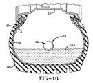
- monitoring assembly 10 is configured to be liquid-tight and float (Fig. 10) on a variety of liquids 110 such as water, Tire Life®, or other liquids. Most liquids 110 disposed within tire 16 will have a specific gravity of 1 or higher. As such, the specific gravity of assembly 10 must be less than 1 in these embodiments. Assembly 10 may be configured to float by fabricating protective body 14 entirely from materials that float or by trapping a sufficient amount of air within protective body 14 to cause assembly 10 to float.
- protective body 14 is fluid-tight to prevent fluid from entering protective body 14 when assembly 10 is floating in liquid.
- Assembly 10 has a longer life when it floats on the upper surface of liquid 110 and the transmissions to and from tire 16 are improved when assembly 10 is not surrounded by liquid 110.
- Wings 50 or 102 also function in liquid 110 to consistently position assembly 10 within tire 16.
- the improved monitoring assembly for a pneumatic tire is simplified, provides an effective, safe, inexpensive, and efficient device that achieves all the enumerated objectives, provides for eliminating difficulties encountered with prior devices, and solves problems and obtains new results in the art.
Landscapes
- Engineering & Computer Science (AREA)
- Mechanical Engineering (AREA)
- Measuring Fluid Pressure (AREA)
- Arrangements For Transmission Of Measured Signals (AREA)
- Tires In General (AREA)
Claims (19)
- Kombination eines Luftreifens (16) und einer Überwachungsvorrichtung (10), wobei der Luftreifen einen Aufbau besitzt, der auf einer Felge (18) unter Ausbildung einer Kammer (20) zwischen dem Aufbau und der Felge gelagert ist,
eine Flüssigkeit (110), die im Luftreifen angeordnet ist, wobei die Flüssigkeit ein spezifisches Gewicht besitzt,
und wobei die Überwachungsvorrichtung (10) lose innerhalb der Kammer (20) angeordnet ist, wodurch sich die Überwachungsvorrichtung frei innerhalb der Kammer bewegt und lediglich durch den Aufbau und die Felge (18) eingeschränkt ist, dadurch gekennzeichnet, dass die Überwachungsvorrichtung ein spezifisches Gewicht geringer als das spezifische Gewicht der Flüssigkeit (110) besitzt, so dass die Überwachungsvorrichtung (10) in/auf der Flüssigkeit schwimmt. - Kombination nach Anspruch 1, bei der die Überwachungsvorrichtung eine elektronische Überwachungseinrichtung (12) umfasst.
- Kombination nach.Anspruch 2, bei der die elektronische Überwachungseinrichtung einen Drucksensor (30) umfasst.
- Kombination nach Anspruch 3, bei der die elektronische Überwachungseinrichtung von einem flüssigkeitsdichtem Schutzgehäuse (14) umgeben ist.
- Kombination nach Anspruch 4, bei der das Schutzgehäuse ein Belüftungsrohr (38) umfasst, das die Verbindung zwischen dem Drucksensor (30) und der Atmosphäre herstellt, die das Schutzgehäuse umgibt.
- Kombination nach Anspruch 5, ferner umfassend ein Übertragungsgel (40), das im wesentlichen das Belüftungsrohr (38) ausfüllt.
- Kombination nach Anspruch 6, ferner umfassend eine Membran (44), die sich quer über das Belüftungsrohr (38) erstreckt.
- Kombination nach Anspruch 4, bei der das Schutzgehäuse eine Einkapselungsschicht (22) angrenzend an die Überwachungseinrichtung umfasst.
- Kombination nach Anspruch 8, bei der die Einkapselungsschicht (22) durch ein im wesentlichen starres oder festes Einkapselungsmaterial gebildet wird.
- Kombination nach Anspruch 9, bei der das Einkapselungsmaterial ein Expoxidharz ist.
- Kombination nach Anspruch 8, bei der die Schutzschicht ferner eine Polsterschicht (26) umfasst, die die Einkapselungsschicht (22) umgibt.
- Kombination nach Anspruch 11, bei der das Polstermaterial ein weiches Gummi ist.
- Kombination nach Anspruch 11, bei der das Polstermaterial ein Schaum ist.
- Kombination nach Anspruch 11, bei der die Schutzschicht ferner eine Hautschicht (14) umfasst, die die Polsterschicht im wesentlichen umhüllt.
- Kombination nach Anspruch 1, ferner umfassend ein Flügelpaar (50), das sich von der Überwachungsvorrichtung (10) nach außen erstreckt.
- Kombination nach Anspruch 15, ferner umfassend eine Antenne (56), die mit der Überwachungsvorrichtung verbunden ist, wobei die Antenne (56) in mindestens einem der Flügel (50) angeordnet ist.
- Überwachungsvorrichtung (10) zur Verwendung in einem Luftreifen, wobei die Vorrichtung folgendes umfasst: mindestens einen Sensor (30) zum Erfassen eines Betriebszustands eines Reifens (16), ein Schutzgehäuse (14), das den Sensor umgibt, wobei das Schutzgehäuse eine ausreichende Krümmung besitzt, damit das Gehäuse auf der Innenseite des Reifens (16) abrollen kann, gekennzeichnet durch
Kombination des Schutzgehäuses (14) und des Sensors (30), die ein spezifisches Gewicht < 1 besitzen, so dass die Überwachungsvorrichtung (10) auf den Flüssigkeiten (110) schwimmt, die ein spezifisches Gewicht von 1 und höher besitzen. - Vorrichtung nach Anspruch 17, bei der das Schutzgehäuse (14) flüssigkeitsdicht ist und eine Einkapselungsschicht (22) umfasst, die angrenzend an den Sensor (30) angeordnet ist, sowie eine Außenhaut (14) und ein Polster (26), das zwischen der Außenhaut (14) und der Einkapselungsschicht (22) angeordnet ist.
- Vorrichtung nach Anspruch 18, ferner umfassend ein Flügelpaar (50), das sich vom Schutzgehäuse (14) erstreckt.
Applications Claiming Priority (3)
| Application Number | Priority Date | Filing Date | Title |
|---|---|---|---|
| US09/608,425 US6360594B1 (en) | 1998-11-13 | 2000-06-30 | Non-attached monitoring assembly for pneumatic tire |
| US608425 | 2000-06-30 | ||
| PCT/US2001/020404 WO2002002358A1 (en) | 2000-06-30 | 2001-06-26 | Non-attached monitoring assembly for pneumatic tire |
Publications (2)
| Publication Number | Publication Date |
|---|---|
| EP1294583A1 EP1294583A1 (de) | 2003-03-26 |
| EP1294583B1 true EP1294583B1 (de) | 2004-10-20 |
Family
ID=24436453
Family Applications (1)
| Application Number | Title | Priority Date | Filing Date |
|---|---|---|---|
| EP01950531A Expired - Lifetime EP1294583B1 (de) | 2000-06-30 | 2001-06-26 | Lose überwachungsvorrichtung für reifen |
Country Status (8)
| Country | Link |
|---|---|
| US (2) | US6360594B1 (de) |
| EP (1) | EP1294583B1 (de) |
| JP (1) | JP4469937B2 (de) |
| AU (2) | AU7151201A (de) |
| CA (1) | CA2411722C (de) |
| DE (1) | DE60106615T2 (de) |
| MX (1) | MXPA02011220A (de) |
| WO (1) | WO2002002358A1 (de) |
Families Citing this family (25)
| Publication number | Priority date | Publication date | Assignee | Title |
|---|---|---|---|---|
| US7009506B2 (en) * | 1998-02-10 | 2006-03-07 | Bridgestone Firestone North American Tire, Llc | Electronic monitoring device and patch assembly |
| US6360594B1 (en) * | 1998-11-13 | 2002-03-26 | Bridgestone/Firestone North American Tire, Llc | Non-attached monitoring assembly for pneumatic tire |
| US6919799B2 (en) | 1999-04-29 | 2005-07-19 | Bridgestone/Firestone North American Tire, Llc | Monitoring device and tire combination |
| US6688353B1 (en) * | 2000-03-31 | 2004-02-10 | Bridgestone/Firestone North American Tire, Llc | Attachment patch for mounting an electronic monitoring device to the inside of a pneumatic tire |
| US8266465B2 (en) | 2000-07-26 | 2012-09-11 | Bridgestone Americas Tire Operation, LLC | System for conserving battery life in a battery operated device |
| US7161476B2 (en) | 2000-07-26 | 2007-01-09 | Bridgestone Firestone North American Tire, Llc | Electronic tire management system |
| US6888449B2 (en) * | 2002-10-09 | 2005-05-03 | Delphi Technologies, Inc. | Circuits for coupling signals carrying information to a tire pressure monitoring system in the absence of a receiver |
| US7002456B2 (en) * | 2003-01-13 | 2006-02-21 | Delphi Technologies, Inc. | Receiver circuit and method for tire pressure monitoring system |
| ES2348131T3 (es) * | 2003-02-04 | 2010-11-30 | Bridgestone Americas Tire Operations, Llc | Dispositivo de monitorización de neumáticos no fijado. |
| US6910372B2 (en) * | 2003-03-21 | 2005-06-28 | Bridgestone/Firestone North American Tire, Llc | Non-attached electronic monitoring device for tire |
| JP4816095B2 (ja) * | 2006-01-20 | 2011-11-16 | 日産自動車株式会社 | タイヤ空気圧センサ取付構造およびタイヤホイール |
| DE102010016378B4 (de) * | 2010-04-09 | 2020-10-15 | Continental Reifen Deutschland Gmbh | Reifenmodul für Fahrzeugreifen |
| US8723661B2 (en) * | 2011-10-31 | 2014-05-13 | Hong Kong Applied Science and Technology Research Institute Company Limited | Mount-free tire pressure monitoring system |
| US9016117B2 (en) | 2012-05-23 | 2015-04-28 | Yuval Solomon | Tire monitoring apparatus, system and method of using the same |
| US8939020B2 (en) | 2012-12-05 | 2015-01-27 | Caterpillar Inc. | Spherical monitoring device for pneumatic tires |
| US20170350241A1 (en) * | 2016-05-13 | 2017-12-07 | Ningbo Wanyou Deepwater Energy Science & Technology Co.,Ltd. | Data Logger and Charger Thereof |
| US20170328197A1 (en) * | 2016-05-13 | 2017-11-16 | Ningbo Wanyou Deepwater Energy Science & Technolog Co.,Ltd. | Data Logger, Manufacturing Method Thereof and Real-time Measurement System Thereof |
| US20180111345A1 (en) * | 2016-10-25 | 2018-04-26 | Robert L. Barnett | System and method for detecting the presence and/or measuring the quantity of liquid within a tire |
| TWI643765B (zh) * | 2017-10-13 | 2018-12-11 | 為升電裝工業股份有限公司 | 具有車輪平衡作用之胎壓偵測器及其車輪平衡系統 |
| TWI656044B (zh) * | 2018-02-27 | 2019-04-11 | 為升電裝工業股份有限公司 | 具有外殼保護之胎壓偵測器 |
| CN108327466A (zh) * | 2018-03-30 | 2018-07-27 | 上海为彪汽配制造有限公司 | 具有外壳保护的胎压感测器 |
| US10710419B2 (en) * | 2018-06-11 | 2020-07-14 | Honda Motor Co., Ltd. | Sensing assembly for detection of temperature of tire |
| AU2019206104A1 (en) * | 2018-07-25 | 2020-02-13 | Cub Elecparts Inc. | Spherical tire pressure detection device |
| CN109291740B (zh) * | 2018-11-07 | 2024-09-10 | 上海为彪汽配制造有限公司 | 一种具有自发电的胎压监测系统 |
| DE102021206758A1 (de) * | 2021-06-29 | 2022-12-29 | Continental Reifen Deutschland Gmbh | Betriebsvorrichtung |
Family Cites Families (11)
| Publication number | Priority date | Publication date | Assignee | Title |
|---|---|---|---|---|
| US2222047A (en) * | 1938-04-06 | 1940-11-19 | Goodrich Co B F | Apparatus for removing liquid from tires |
| US4067235A (en) | 1974-11-27 | 1978-01-10 | Consolidated Freightways, Inc. | Method and apparatus for measuring air pressure in pneumatic tires |
| US4169497A (en) * | 1977-05-31 | 1979-10-02 | Yasuo Tsuruta | Method and device for automatically increasing the restoring force of a pneumatic tire |
| US4343338A (en) * | 1981-02-25 | 1982-08-10 | Caterpillar Tractor Co. | Tire cooling system and method |
| DE3718471A1 (de) | 1987-06-02 | 1988-12-22 | Christoph Breit | Einrichtung zum schutz der aggregate und der ladung von kraftfahrzeugen |
| US5500065A (en) * | 1994-06-03 | 1996-03-19 | Bridgestone/Firestone, Inc. | Method for embedding a monitoring device within a tire during manufacture |
| US5679187A (en) * | 1995-09-20 | 1997-10-21 | Caterpillar Inc. | Bounce damping in elastomeric tires |
| JP2759073B2 (ja) * | 1996-06-28 | 1998-05-28 | 伊三五 美浦 | 空気入りタイヤ |
| US6025777A (en) | 1998-03-11 | 2000-02-15 | Fuller Brothers, Inc. | Off-the-road tire temperature and pressure monitoring system |
| US6082192A (en) * | 1998-11-13 | 2000-07-04 | Bridgestone/Firestone, Inc. | Non-attached monitoring assembly for pneumatic tire |
| US6360594B1 (en) * | 1998-11-13 | 2002-03-26 | Bridgestone/Firestone North American Tire, Llc | Non-attached monitoring assembly for pneumatic tire |
-
2000
- 2000-06-30 US US09/608,425 patent/US6360594B1/en not_active Expired - Lifetime
-
2001
- 2001-06-26 CA CA002411722A patent/CA2411722C/en not_active Expired - Fee Related
- 2001-06-26 WO PCT/US2001/020404 patent/WO2002002358A1/en not_active Ceased
- 2001-06-26 AU AU7151201A patent/AU7151201A/xx active Pending
- 2001-06-26 EP EP01950531A patent/EP1294583B1/de not_active Expired - Lifetime
- 2001-06-26 JP JP2002506960A patent/JP4469937B2/ja not_active Expired - Fee Related
- 2001-06-26 MX MXPA02011220A patent/MXPA02011220A/es active IP Right Grant
- 2001-06-26 AU AU2001271512A patent/AU2001271512B2/en not_active Ceased
- 2001-06-26 DE DE60106615T patent/DE60106615T2/de not_active Expired - Lifetime
- 2001-08-22 US US09/934,960 patent/US6516660B1/en not_active Expired - Lifetime
Also Published As
| Publication number | Publication date |
|---|---|
| EP1294583A1 (de) | 2003-03-26 |
| DE60106615D1 (de) | 2004-11-25 |
| JP4469937B2 (ja) | 2010-06-02 |
| MXPA02011220A (es) | 2004-03-16 |
| CA2411722A1 (en) | 2002-01-10 |
| US6360594B1 (en) | 2002-03-26 |
| AU7151201A (en) | 2002-01-14 |
| WO2002002358A1 (en) | 2002-01-10 |
| US6516660B1 (en) | 2003-02-11 |
| DE60106615T2 (de) | 2005-10-27 |
| CA2411722C (en) | 2009-09-29 |
| JP2004502183A (ja) | 2004-01-22 |
| AU2001271512B2 (en) | 2005-01-20 |
Similar Documents
| Publication | Publication Date | Title |
|---|---|---|
| EP1294583B1 (de) | Lose überwachungsvorrichtung für reifen | |
| US6543277B2 (en) | Non-attached monitoring assembly for pneumatic tire | |
| CA2289385C (en) | Non-attached monitoring assembly for pneumatic tire | |
| AU2001271512A1 (en) | Non-attached monitoring assembly for pneumatic tire | |
| EP1562763B1 (de) | Lose überwachungsvorrichtung für reifen | |
| US8939020B2 (en) | Spherical monitoring device for pneumatic tires | |
| KR101094652B1 (ko) | 타이어용 비-부착식 전자 모니터링 장치 | |
| MXPA99009541A (es) | Estructura de verificacion no conectada para neumatico | |
| WO2005047029A1 (en) | Tire monitoring system |
Legal Events
| Date | Code | Title | Description |
|---|---|---|---|
| PUAI | Public reference made under article 153(3) epc to a published international application that has entered the european phase |
Free format text: ORIGINAL CODE: 0009012 |
|
| 17P | Request for examination filed |
Effective date: 20021206 |
|
| AK | Designated contracting states |
Kind code of ref document: A1 Designated state(s): AT BE CH CY DE DK ES FI FR GB GR IE IT LI LU MC NL PT SE TR |
|
| AX | Request for extension of the european patent |
Extension state: AL LT LV MK RO SI |
|
| GRAP | Despatch of communication of intention to grant a patent |
Free format text: ORIGINAL CODE: EPIDOSNIGR1 |
|
| RBV | Designated contracting states (corrected) |
Designated state(s): DE FR GB |
|
| GRAS | Grant fee paid |
Free format text: ORIGINAL CODE: EPIDOSNIGR3 |
|
| GRAA | (expected) grant |
Free format text: ORIGINAL CODE: 0009210 |
|
| AK | Designated contracting states |
Kind code of ref document: B1 Designated state(s): DE FR GB |
|
| REG | Reference to a national code |
Ref country code: GB Ref legal event code: FG4D |
|
| REG | Reference to a national code |
Ref country code: IE Ref legal event code: FG4D |
|
| REF | Corresponds to: |
Ref document number: 60106615 Country of ref document: DE Date of ref document: 20041125 Kind code of ref document: P |
|
| LTIE | Lt: invalidation of european patent or patent extension |
Effective date: 20041020 |
|
| ET | Fr: translation filed | ||
| PLBE | No opposition filed within time limit |
Free format text: ORIGINAL CODE: 0009261 |
|
| STAA | Information on the status of an ep patent application or granted ep patent |
Free format text: STATUS: NO OPPOSITION FILED WITHIN TIME LIMIT |
|
| 26N | No opposition filed |
Effective date: 20050721 |
|
| REG | Reference to a national code |
Ref country code: FR Ref legal event code: PLFP Year of fee payment: 16 |
|
| REG | Reference to a national code |
Ref country code: FR Ref legal event code: PLFP Year of fee payment: 17 |
|
| PGFP | Annual fee paid to national office [announced via postgrant information from national office to epo] |
Ref country code: GB Payment date: 20170526 Year of fee payment: 17 Ref country code: FR Payment date: 20170518 Year of fee payment: 17 |
|
| PGFP | Annual fee paid to national office [announced via postgrant information from national office to epo] |
Ref country code: DE Payment date: 20170623 Year of fee payment: 17 |
|
| REG | Reference to a national code |
Ref country code: DE Ref legal event code: R119 Ref document number: 60106615 Country of ref document: DE |
|
| GBPC | Gb: european patent ceased through non-payment of renewal fee |
Effective date: 20180626 |
|
| PG25 | Lapsed in a contracting state [announced via postgrant information from national office to epo] |
Ref country code: FR Free format text: LAPSE BECAUSE OF NON-PAYMENT OF DUE FEES Effective date: 20180630 Ref country code: GB Free format text: LAPSE BECAUSE OF NON-PAYMENT OF DUE FEES Effective date: 20180626 Ref country code: DE Free format text: LAPSE BECAUSE OF NON-PAYMENT OF DUE FEES Effective date: 20190101 |