EP1293993A2 - Superconducting magnet and magnetic resonance imaging apparatus using the same - Google Patents
Superconducting magnet and magnetic resonance imaging apparatus using the same Download PDFInfo
- Publication number
- EP1293993A2 EP1293993A2 EP02256339A EP02256339A EP1293993A2 EP 1293993 A2 EP1293993 A2 EP 1293993A2 EP 02256339 A EP02256339 A EP 02256339A EP 02256339 A EP02256339 A EP 02256339A EP 1293993 A2 EP1293993 A2 EP 1293993A2
- Authority
- EP
- European Patent Office
- Prior art keywords
- coil
- coolant
- containers
- superconducting
- coil containers
- Prior art date
- Legal status (The legal status is an assumption and is not a legal conclusion. Google has not performed a legal analysis and makes no representation as to the accuracy of the status listed.)
- Withdrawn
Links
Images





Classifications
-
- A—HUMAN NECESSITIES
- A61—MEDICAL OR VETERINARY SCIENCE; HYGIENE
- A61B—DIAGNOSIS; SURGERY; IDENTIFICATION
- A61B5/00—Measuring for diagnostic purposes; Identification of persons
- A61B5/05—Detecting, measuring or recording for diagnosis by means of electric currents or magnetic fields; Measuring using microwaves or radio waves
- A61B5/055—Detecting, measuring or recording for diagnosis by means of electric currents or magnetic fields; Measuring using microwaves or radio waves involving electronic [EMR] or nuclear [NMR] magnetic resonance, e.g. magnetic resonance imaging
-
- H—ELECTRICITY
- H01—ELECTRIC ELEMENTS
- H01F—MAGNETS; INDUCTANCES; TRANSFORMERS; SELECTION OF MATERIALS FOR THEIR MAGNETIC PROPERTIES
- H01F6/00—Superconducting magnets; Superconducting coils
- H01F6/04—Cooling
-
- G—PHYSICS
- G01—MEASURING; TESTING
- G01R—MEASURING ELECTRIC VARIABLES; MEASURING MAGNETIC VARIABLES
- G01R33/00—Arrangements or instruments for measuring magnetic variables
- G01R33/20—Arrangements or instruments for measuring magnetic variables involving magnetic resonance
- G01R33/28—Details of apparatus provided for in groups G01R33/44 - G01R33/64
- G01R33/38—Systems for generation, homogenisation or stabilisation of the main or gradient magnetic field
- G01R33/3806—Open magnet assemblies for improved access to the sample, e.g. C-type or U-type magnets
-
- G—PHYSICS
- G01—MEASURING; TESTING
- G01R—MEASURING ELECTRIC VARIABLES; MEASURING MAGNETIC VARIABLES
- G01R33/00—Arrangements or instruments for measuring magnetic variables
- G01R33/20—Arrangements or instruments for measuring magnetic variables involving magnetic resonance
- G01R33/28—Details of apparatus provided for in groups G01R33/44 - G01R33/64
- G01R33/38—Systems for generation, homogenisation or stabilisation of the main or gradient magnetic field
- G01R33/381—Systems for generation, homogenisation or stabilisation of the main or gradient magnetic field using electromagnets
- G01R33/3815—Systems for generation, homogenisation or stabilisation of the main or gradient magnetic field using electromagnets with superconducting coils, e.g. power supply therefor
-
- G—PHYSICS
- G01—MEASURING; TESTING
- G01R—MEASURING ELECTRIC VARIABLES; MEASURING MAGNETIC VARIABLES
- G01R33/00—Arrangements or instruments for measuring magnetic variables
- G01R33/20—Arrangements or instruments for measuring magnetic variables involving magnetic resonance
- G01R33/28—Details of apparatus provided for in groups G01R33/44 - G01R33/64
- G01R33/38—Systems for generation, homogenisation or stabilisation of the main or gradient magnetic field
- G01R33/385—Systems for generation, homogenisation or stabilisation of the main or gradient magnetic field using gradient magnetic field coils
- G01R33/3854—Systems for generation, homogenisation or stabilisation of the main or gradient magnetic field using gradient magnetic field coils means for active and/or passive vibration damping or acoustical noise suppression in gradient magnet coil systems
Definitions
- the present invention relates to a superconducting magnet and a magnetic resonance imaging apparatus using the superconducting magnet, and particularly to a super conducting magnet suitable for an open-type MRI apparatus not giving block-feeling to a person to be inspected and an MRI apparatus using the superconducting magnet.
- FIG. 10-179546 An example of a conventional superconducting magnet used for an MRI apparatus is disclosed in Japanese Patent Application Laid-Open No.10-179546.
- the conventional superconducting magnet described in the patent gazette is constructed in such that a coil container containing the superconducting magnet immerged into cooling medium of liquid helium also serves as a helium tank for storing the liquid helium, and a refrigerator for cooling the liquid helium is directly placed in the coil container (the helium container).
- the conventional superconductor for the MRI apparatus has the following problems.
- the vibration of the refrigerator is directly transmitted to the coil container, and the superconducting coil contained in the inside is also vibrated by the vibration to vibrate the generated magnetic flux. Since the vibration of the generated magnetic flux gives a bad influence to the image, no clear image can be obtained.
- the apparatus inherently becomes bulky.
- a space to receive the person to be inspected hereinafter occasionally referred to as subject
- subject a space to receive the person to be inspected
- An object of the present invention is to provide a superconducting magnet in which the vibration of the magnetic flux generated by the superconducting magnet is suppressed so as to not give bad influence to an image by reducing the vibration transmitted from the refrigerator to the coil container containing the superconducting coil, and to provide an MRI apparatus using the superconducting magnet.
- Another object of the present invention to provide an MRI apparatus which can be formed in compact and provide greater space for receiving a subject so as not to give block-feeling to the subject.
- a superconducting magnet comprises superconducting coils; coil containers, each of said coil container containing said superconducting coil together with coolant; and a refrigerator for cooling said coolant, said coil containers being arranged separately from and opposite to each other, a magnetic field space being formed between both of said coil containers, wherein a coolant tank for supplying the coolant to said coil containers is provided separately from said coil containers, and said refrigerator is placed in said coolant tank, a coolant circulation passage connects between said coolant tank and said coil containers, cylindrical spaces are defined in said coil container, and magnetic poles formed from ferromagnetic bodies are arranged within said cylindrical spaces.
- a ferromagnetic member may be arranged on a surface in a reverse side of an opposite surface of each of said coil containers.
- a connecting passage may connect between said coil containers each other, and lead wires connecting said superconducting coils in said coil containers to each other pass through the inside of said connecting passage.
- a flexible portion may be provided in an intermediate portion of said coolant circulation passage.
- a superconducting magnet comprises superconducting coils; coil containers, each of said coil container containing said superconducting coil together with coolant; and a refrigerator for cooling said coolant, said coil containers being arranged separately from and opposite to each other, a magnetic field space being formed between both of said coil containers, wherein a coolant tank for supplying the coolant to said coil containers is provided separately from said coil containers, and an amount of said coolant in said coil container is a necessary minimum amount for maintaining superconducting coil in superconducting state.
- a superconducting magnet comprises superconducting coils; coil containers, each of said coil container containing said superconducting coil together with coolant; and a refrigerator for cooling said coolant, said coil containers being arranged separately from and opposite to each other, a magnetic field space being formed between both of said coil containers, wherein cylindrical spaces are defined in said coil container, and magnetic poles formed from ferromagnetic bodies are arranged within said cylindrical spaces, and an angle of visibility in vertical direction defined by said magnetic poles as viewing an opening portion of upper and lower coil containers from a center of said superconducting magnet, is greater than or equal to 30 .
- a connecting passage connects between said coil containers each other, and lead wires connecting said superconducting coils in said coil containers to each other may pass through the inside of said connecting passage.
- a superconducting magnet comprises superconducting coils; coil containers, each of said coil container containing said superconducting coil together with coolant; and a refrigerator for cooling said coolant, said coil containers being arranged separately from and opposite to each other, a magnetic field space being formed between both of said coil containers, wherein a coolant tank for supplying the coolant to said coil containers is provided separately from said coil containers, , said coil container and said coolant tank are connected to a coolant passage, a crossover from said superconducting coil is arranged within said coolant tank, and said crossover and a permanent current switch are connected within said coolant tank.
- a bed capable of mounting a body to be inspected and moving between said coil containers of said superconducting magnets opposite to each other; and a control unit for analyzing a nuclear magnetic resonance signal from the body to be inspected.
- the MRI apparatus comprises a superconducting magnet which is comprised of superconducting coils, not shown, coil containers 11 and 12 each containing the superconducting coil together with a coolant (for example, liquid helium), a coolant tank 41 for storing the coolant and a refrigerator for cooling the coolant; a bed 90 for mounting a body to be inspected; and a control unit 100 for analyzing a nuclear resonance signal from the body to be analyzed.
- the coil containers 11 and 12 are arranged separately from and opposite to each other, and a magnetic field space is formed between both of the coil containers 11 and 12, and a tomogram is taken by passing the body to be inspected mounted on the bed 90.
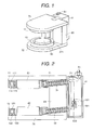
- Figs. 1, 2 and 3 show the first embodiment of a superconducting magnet.
- Fig. 3 is illustrated with removing magnetic pole supporting members 71 and 72, magnetic poles 81 and 82 and a support member 63.
- the coolant tank (hereinafter, referred to as He tank) 41 for supplying the coolant to the coil containers 11 and 12 is provided separately from the coil containers 11 and 12, the refrigerator 51 is arranged in the He tank 41, and a coolant circulation passage 31 (pipe) connects between the He tank 41 and the coil containers 11 and 12.
- the coil containers 11 and 12 are supported by the He tank 41 through a support member 61.
- the magnetic poles 81 and 82 formed from ferromagnetic body are disposed within the cylindrical spaces.
- An upper coil portion including the magnetic pole 81 and a lower coil portion including the magnetic pole 82 are supported by the support member 63.
- the upper and lower containers 11 and 12 containing the magnetic poles 81 and 82 are supported by the magnetic pole supporting members 71 and 72.
- the upper and lower containers 11 and 12 are supported by the support member 63 via the magnetic pole supporting members 71 and 72.
- the coil containers 11 and 12 and the He tank 41 are connected with each other through the coolant circulation passages 31 and 32, respectively. By this, liquid state He is supplied to the coil containers 11 and 12 from the He tank 41.
- the refrigerator 51 is installed in the He tank 41. The refrigerator 51 is adapted to condense He gas collected to the He tank 41.
- the coil container 11 is formed by enclosing the superconducting coil in a He container 112 together with coolant. Furthermore, a shield plate 111 is provided for evacuated insulation and for cooling by the refrigerator 51. The superconducting crossover 711 is disposed within the He tank 41. Here, a superconducting switch 602 and a protecting resistor 601 are connected.
- the vibration of the refrigerator 51 hardly propagates the coil containers 11 and 12 because the coil containers 11 and 12 are placed at a position distant from the He tank through the passage 31. Therefore, the effect of the vibration on the magnetic uniformity in the magnetic field space formed by the superconducting coils can be reduced.
- the magnetic poles 81 and 82 are provided, a uniform magnetic field is formed at the center portion where magnetic field tends to be non-uniform, without increasing magnets, to permit production of MRI at low cost.
- Fig. 4 is a diagrammatic illustration showing portion around the coil of Fig. 1.
- angle of visibility is defined. Namely, as viewing opening portion of the upper coil 11 and the lower coil 12 from the center O of the magnets 81 and 82, an angle in vertical direction defined by the magnetic poles is referred to as angle of visibility.
- angle of visibility an angle in vertical direction defined by the magnetic poles.
- the angle of visibility can be made larger, e.g. greater than or equal to 30 .
- the construction of the present embodiment is that a vibration isolating means 33 and 34 are provided in intermediate portions of the passages 31 and 32 for connecting the coil containers 11 and 12 to the He tank 41 described in the above-described embodiments, respectively.
- the superconducting magnet of the present invention is essentially constructed so as to hardly receive the vibration of the refrigerator because the passage is provided between the coil containers 11, 12 and the coolant tank 41 in which the refrigerator is placed.
- the vibration isolating means described above in the passages 31 and 32 the isolation of vibration can be further secured.
- vibration isolating means it is possible to effectively suppress the vibration of the refrigerator to transmit to the coil containers.
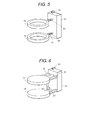
- FIG. 6 shows a third embodiment of a superconducting magnet.
- the coolant tank (hereinafter, referred to as He tank) 41 for supplying the coolant to the coil containers 11 and 12 is provided separately from the coil containers 11 and 12, the refrigerator 51 is arranged in the He tank 41, and a coolant circulation passage 31 (pipe) connects between the He tank 41 and the coil containers 11 and 12.
- the coil containers 11 and 12 are supported by the He tank 41 through a support member 61.
- a connecting passage 21 connects between the upper and the lower coil containers 11 and 12, and liquid He and He gas pass through the inside of the connecting passage 21, and coil connecting wires also pass through.
- a passage 31 connects between the coil container 11 and the He tank 41 so that the liquid He can supplied from the He tank 41 to the coil container 11 through the passage 31 and the He gas can be returned to the He tank 41.
- the refrigerator 51 is installed in the He tank 41 as described above, and the role of the refrigerator 51 is to condense the He gas returned to the He tank 41.
- the vibration of the refrigerator 51 hardly propagates the coil containers 11 and 12 because the coil containers 11 and 12 are placed at a position distant from the He tank through the passage 31. Therefore, the effect of the vibration on the magnetic uniformity in the magnetic field space formed by the superconducting coils can be reduced.
- FIG. 7 shows a fourth embodiment of a superconducting magnet.
- the construction of the present embodiment is that in the third embodiment, the coil container support member 62 for supporting the upper and the lower coil containers 11 and 12 is provided separately from the He tank 41.
- the construction has the same effect as that of the first embodiment, the structure having the coil container support member 62 is more reasonable than that of the embodiment 1 when the He tank 41 can be made compact.
- FIG. 8 shows a fifth embodiment of a superconducting magnet.
- the construction of the present embodiment is that in addition to the construction of the third embodiment, the ferromagnetic members 71 and 72 are arranged in the outside (in the reverse side of the opposite surfaces) of the coil containers 11 and 12.
- the leakage magnetic field can be reduced by placing the ferromagnetic members 71 and 72 in those positions.
- it is possible to improve the magnetic field shielding performance by arranging active shielding coils on the ferromagnetic members 71 and 72.
- the coil container 11 is connected to the He tank 41 through a passage, not shown in the figure.
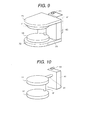
- FIG. 9 and FIG. 10 show a sixth embodiment of superconducting magnet.
- FIG. 10 shows the state that the magnetic pole support members 71 and 72, the magnetic poles and the support member 63 illustrated in the structure of FIG. 9 are removed.
- the construction of the present embodiment is that the coil containers 11 and 12 having the ferromagnetic members 71 and 72 in the outside are supported by another member 63 separated from the He tank 41.
- the structure having another support 63 separately from the He tank 41 is more economical when the He tank 41 can be made compact. Further, when the support 63 is made of a ferromagnetic material (iron), a magnetic circuit is formed together with the upper and the lower ferromagnetic members 71 and 72, and accordingly the leakage magnetic field can be more effectively suppressed.
- a ferromagnetic material iron
- FIG. 11 shows a seventh embodiment of a superconducting magnet.
- the construction of the present embodiment is that annular spatial portions are formed in the coil containers 11a and 12a and then magnetic poles 81 and 82 made of a ferromagnetic material are placed into the annular spatial portions, respectively, and the He tank 41 is also used for supporting the upper coil portion and the lower coil portion including the magnetic poles 81 and 82. That is, the coil containers 11a and 12a having the magnetic poles 81 and 82 are supported by the He tank 41 through the support members 64 and 65.
- the support members 64 and 65 are made of a non-magnetic material.
- the same effect as the effect of the embodiment 1 can be also obtained by the construction of the present embodiment. Since the magnetic poles 81 and 82 are provided, the superconducting magnet having the magnetic poles 81 and 82 may be more economically constructed depending on the magnetic field intensity or the magnetic field uniformity.
- FIG. 12 shows an eighth embodiment of a superconducting magnet.
- the construction of the present embodiment is that another support member 63 is provided separately from the He tank 41, and the coil containers 11a and 12a are supported by the support member 63 integrated with the support members 64 and 65 in a single unit not by the He tank 41.
- the construction of the present embodiment can also obtain the same effect as the effect of the embodiment 1, and is more economical when the He tank 41 can be made compact.
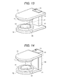
- FIG. 13 shows a ninth embodiment of a superconducting magnet.
- the construction of the present embodiment is that the upper and the lower coil containers 11 and 12 having the individual magnetic poles are covered with the magnetic pole support members 71 and 72 though which the upper and the lower coil containers 11 and 12 are supported by the He tank 41, respectively.
- the construction of the present embodiment can obtain the same effect as that of the above-mentioned embodiments, and is effective to reduce the leakage magnetic field. In order to further reduce the leakage magnetic field, it is effective to place magnetic shielding coils in the outer sides of the ferromagnetic members.
- FIG. 14 and FIG. 15 show a tenth embodiment of superconducting magnet.
- FIG. 15 shows the state that the magnetic pole support members 71 and 72, the magnetic poles and the support member 63 illustrated in the structure of FIG. 14 are removed.
- the construction of the present embodiment is that another support member 63 is provided separately from the He tank 41, and the coil containers 11 and 12 are supported by the support member 63 integrated with the magnetic pole support members 71 and 72 provided so as to cover the coil containers 11 and 12 in a single unit, and further that the magnetic pole support members 71 and 72 are made of a ferromagnetic material, and the support member 63 connecting between the upper and the lower coil containers 11 and 12 are also made of a ferromagnetic material.
- the construction of the present embodiment can obtain the same effect as that of the above-mentioned embodiments, and the magnetic fluxes can be more restrained by combining the magnetic circuit to the magnetic poles 81 and 82 to further reduce the leakage magnetic field.
- the construction of the embodiment shown in FIG. 16 is that the magnets are horizontally arranged so that the coil containers 11 and 12 are horizontally opposite to each other. In the present embodiment, it is possible to construct an apparatus in which the body to be inspected can be inspected while keeping standing.
Landscapes
- Physics & Mathematics (AREA)
- Health & Medical Sciences (AREA)
- Condensed Matter Physics & Semiconductors (AREA)
- General Physics & Mathematics (AREA)
- Engineering & Computer Science (AREA)
- Life Sciences & Earth Sciences (AREA)
- Electromagnetism (AREA)
- Power Engineering (AREA)
- Nuclear Medicine, Radiotherapy & Molecular Imaging (AREA)
- Medical Informatics (AREA)
- Molecular Biology (AREA)
- Biophysics (AREA)
- Pathology (AREA)
- Biomedical Technology (AREA)
- Heart & Thoracic Surgery (AREA)
- High Energy & Nuclear Physics (AREA)
- Radiology & Medical Imaging (AREA)
- Surgery (AREA)
- Animal Behavior & Ethology (AREA)
- General Health & Medical Sciences (AREA)
- Public Health (AREA)
- Veterinary Medicine (AREA)
- Magnetic Resonance Imaging Apparatus (AREA)
Abstract
Description
a coolant tank for supplying the coolant to said coil containers is provided separately from said coil containers, and said refrigerator is placed in said coolant tank, a coolant circulation passage connects between said coolant tank and said coil containers, cylindrical spaces are defined in said coil container, and magnetic poles formed from ferromagnetic bodies are arranged within said cylindrical spaces.
a coolant tank for supplying the coolant to said coil containers is provided separately from said coil containers, and an amount of said coolant in said coil container is a necessary minimum amount for maintaining superconducting coil in superconducting state.
cylindrical spaces are defined in said coil container, and magnetic poles formed from ferromagnetic bodies are arranged within said cylindrical spaces, and an angle of visibility in vertical direction defined by said magnetic poles as viewing an opening portion of upper and lower coil containers from a center of said superconducting magnet, is greater than or equal to 30 .
a coolant tank for supplying the coolant to said coil containers is provided separately from said coil containers, , said coil container and said coolant tank are connected to a coolant passage, a crossover from said superconducting coil is arranged within said coolant tank, and said crossover and a permanent current switch are connected within said coolant tank.
Claims (9)
- A superconducting magnet comprising superconducting coils; coil containers, each of said coil container containing said superconducting coil together with coolant; and a refrigerator for cooling said coolant, said coil containers being arranged separately from and opposite to each other, a magnetic field space being formed between both of said coil containers, wherein
a coolant tank for supplying the coolant to said coil containers is provided separately from said coil containers, and said refrigerator is placed in said coolant tank, a coolant circulation passage connects between said coolant tank and said coil containers, cylindrical spaces are defined in said coil container, and magnetic poles formed from ferromagnetic bodies are arranged within said cylindrical spaces. - A superconducting magnet according to claim 1, wherein a ferromagnetic member is arranged on a surface in a reverse side of an opposite surface of each of said coil containers.
- A superconducting magnet according to claim 1 or 2, wherein a connecting passage connects between said coil containers each other, and lead wires connecting said superconducting coils in said coil containers to each other pass through the inside of said connecting passage.
- A superconducting magnet according to any one of claims 1 to 3, wherein a flexible portion is provided in an intermediate portion of said coolant circulation passage.
- A superconducting magnet comprising superconducting coils; coil containers, each of said coil container containing said superconducting coil together with coolant; and a refrigerator for cooling said coolant, said coil containers being arranged separately from and opposite to each other, a magnetic field space being formed between both of said coil containers, wherein
a coolant tank for supplying the coolant to said coil containers is provided separately from said coil containers, and an amount of said coolant in said coil container is a necessary minimum amount for maintaining superconducting coil in superconducting state. - A superconducting magnet comprising superconducting coils; coil containers, each of said coil container containing said superconducting coil together with coolant; and a refrigerator for cooling said coolant, said coil containers being arranged separately from and opposite to each other, a magnetic field space being formed between both of said coil containers, wherein
cylindrical spaces are defined in said coil container, and magnetic poles formed from ferromagnetic bodies are arranged within said cylindrical spaces, and an angle of visibility in vertical direction defined by said magnetic poles as viewing an opening portion of upper and lower coil containers from a center of said superconducting magnet, is greater than or equal to 30. - A superconducting magnet according to claim 5 or 6, wherein a connecting passage connects between said coil containers each other, and lead wires connecting said superconducting coils in said coil containers to each other pass through the inside of said connecting passage.
- A superconducting magnet comprising superconducting coils; coil containers, each of said coil container containing said superconducting coil together with coolant; and a refrigerator for cooling said coolant, said coil containers being arranged separately from and opposite to each other, a magnetic field space being formed between both of said coil containers, wherein
a coolant tank for supplying the coolant to said coil containers is provided separately from said coil containers, said coil container and said coolant tank are connected to a coolant passage, a crossover from said superconducting coil is arranged within said coolant tank, and said crossover and a permanent current switch are connected within said coolant tank. - A magnetic resonance imaging apparatus comprising the superconducting magnets described in any one of claims 1 to 8; a bed capable of mounting a body to be inspected and moving between said coil containers of said superconducting magnets opposite to each other; and a control unit for analyzing a nuclear magnetic resonance signal from the body to be inspected.
Applications Claiming Priority (2)
| Application Number | Priority Date | Filing Date | Title |
|---|---|---|---|
| JP2001275895 | 2001-09-12 | ||
| JP2001275895 | 2001-09-12 |
Publications (2)
| Publication Number | Publication Date |
|---|---|
| EP1293993A2 true EP1293993A2 (en) | 2003-03-19 |
| EP1293993A3 EP1293993A3 (en) | 2003-04-09 |
Family
ID=19100681
Family Applications (1)
| Application Number | Title | Priority Date | Filing Date |
|---|---|---|---|
| EP02256339A Withdrawn EP1293993A3 (en) | 2001-09-12 | 2002-09-12 | Superconducting magnet and magnetic resonance imaging apparatus using the same |
Country Status (4)
| Country | Link |
|---|---|
| US (1) | US6664876B2 (en) |
| EP (1) | EP1293993A3 (en) |
| KR (1) | KR20030023517A (en) |
| CN (1) | CN1210575C (en) |
Cited By (1)
| Publication number | Priority date | Publication date | Assignee | Title |
|---|---|---|---|---|
| EP2287366A4 (en) * | 2008-05-26 | 2012-11-21 | Toshiba Kk | SUPERCONDUCTING MAGNETIC DEVICE FOR SINGLE CRYSTAL DRAWING DEVICE |
Families Citing this family (12)
| Publication number | Priority date | Publication date | Assignee | Title |
|---|---|---|---|---|
| JP4341375B2 (en) * | 2003-11-06 | 2009-10-07 | 株式会社日立製作所 | Magnetic resonance imaging system |
| US8893516B2 (en) * | 2004-07-02 | 2014-11-25 | Hitachi Medical Corporation | Magnetic resonance imaging device and method of replacing a cryo-cooler therein |
| US7560929B2 (en) * | 2006-08-14 | 2009-07-14 | Fonar Corporation | Ferromagnetic frame magnet with superconducting coils |
| JP4266232B2 (en) * | 2006-11-17 | 2009-05-20 | 株式会社日立製作所 | Superconducting magnet apparatus and magnetic resonance imaging apparatus |
| US20100219833A1 (en) * | 2007-07-26 | 2010-09-02 | Emscan Limited | Magnet assembly |
| EP2511724B1 (en) * | 2008-06-24 | 2019-03-13 | Alberta Health Services | Method of defining a magnetic field for an imaging volume |
| CN102412048A (en) * | 2011-11-16 | 2012-04-11 | 宁波鑫高益磁材有限公司 | Open type superconductive MRI (Magnetic Resonance Imaging) magnet system |
| GB2497342B (en) * | 2011-12-08 | 2014-06-18 | Siemens Plc | Vibration isolation for superconducting magnets |
| DE102014224363A1 (en) * | 2014-11-28 | 2016-06-02 | Siemens Aktiengesellschaft | Device of superconducting technology with coil devices and cooling device as well as vehicle equipped therewith |
| JP7022035B2 (en) * | 2018-08-31 | 2022-02-17 | ジャパンスーパーコンダクタテクノロジー株式会社 | Superconducting magnet device |
| CN115966363A (en) * | 2022-12-19 | 2023-04-14 | 杭州慧翔电液技术开发有限公司 | Superconducting magnet cooling container, superconducting magnet cooling device and monocrystalline silicon manufacturing equipment |
| CN115762953B (en) * | 2023-01-10 | 2023-06-02 | 苏州八匹马超导科技有限公司 | Superconducting magnet cooling device and superconducting magnet equipment |
Family Cites Families (8)
| Publication number | Priority date | Publication date | Assignee | Title |
|---|---|---|---|---|
| JPS5734314A (en) * | 1980-08-11 | 1982-02-24 | Toshiba Corp | Superconductive magnet device |
| US5412363A (en) * | 1991-12-20 | 1995-05-02 | Applied Superconetics, Inc. | Open access superconducting MRI magnet |
| JP2844433B2 (en) * | 1995-05-30 | 1999-01-06 | 岩谷産業株式会社 | Reliquefaction equipment for liquefied gas for cooling of physics and chemistry equipment |
| JP3980105B2 (en) | 1996-12-26 | 2007-09-26 | 株式会社日立メディコ | Static magnetic field generator and magnetic resonance imaging apparatus |
| US5864273A (en) | 1997-03-12 | 1999-01-26 | General Electric Company | Cryocooler vibration isolation and noise reduction in magnetic resonance imaging |
| US6323749B1 (en) * | 1998-07-29 | 2001-11-27 | Fonar Corporation | MRI with superconducting coil |
| JP4079400B2 (en) * | 1998-10-22 | 2008-04-23 | 株式会社日立メディコ | Superconducting magnet device |
| JP2000161803A (en) * | 1998-11-27 | 2000-06-16 | Aisin Seiki Co Ltd | Cooling system |
-
2002
- 2002-06-14 US US10/170,392 patent/US6664876B2/en not_active Expired - Fee Related
- 2002-09-11 KR KR1020020054815A patent/KR20030023517A/en not_active Ceased
- 2002-09-11 CN CNB021529388A patent/CN1210575C/en not_active Expired - Fee Related
- 2002-09-12 EP EP02256339A patent/EP1293993A3/en not_active Withdrawn
Cited By (1)
| Publication number | Priority date | Publication date | Assignee | Title |
|---|---|---|---|---|
| EP2287366A4 (en) * | 2008-05-26 | 2012-11-21 | Toshiba Kk | SUPERCONDUCTING MAGNETIC DEVICE FOR SINGLE CRYSTAL DRAWING DEVICE |
Also Published As
| Publication number | Publication date |
|---|---|
| EP1293993A3 (en) | 2003-04-09 |
| US6664876B2 (en) | 2003-12-16 |
| CN1210575C (en) | 2005-07-13 |
| KR20030023517A (en) | 2003-03-19 |
| US20030048163A1 (en) | 2003-03-13 |
| CN1414395A (en) | 2003-04-30 |
Similar Documents
| Publication | Publication Date | Title |
|---|---|---|
| JP3711659B2 (en) | Open magnetic resonance imaging magnet | |
| EP0817211B1 (en) | Superconducting magnet device and magnetic resonance imaging device using the same | |
| JP3673556B2 (en) | Open magnetic resonance imaging magnet with superconducting shield | |
| JP3654463B2 (en) | Magnetic resonance imaging system | |
| EP1293993A2 (en) | Superconducting magnet and magnetic resonance imaging apparatus using the same | |
| US7528605B2 (en) | Superconductive magnet device and magnetic resonance imaging apparatus | |
| JPH09153408A (en) | Superconducting magnet device | |
| EP0770882B1 (en) | Open MRI superconductive magnet with cryogenic-fluid cooling | |
| US6667676B2 (en) | Superconducting magnet and magnetic resonance imaging apparatus using the same | |
| JP4292261B2 (en) | Magnet apparatus and MRI apparatus using the same | |
| JP3871789B2 (en) | Passive shield superconducting magnet | |
| JP2000279394A (en) | Open magnet with shield | |
| US7049920B2 (en) | Open magnet device and magnetic resonance imaging apparatus comprising it | |
| JP2008130744A (en) | Superconducting magnet device and magnetic resonance imaging device | |
| JP3824412B2 (en) | Superconducting magnet device for crystal pulling device | |
| JP4065747B2 (en) | Superconducting magnet and magnetic resonance imaging apparatus using the same | |
| US20030110564A1 (en) | Magnetic resonance imaging apparatus | |
| JP2002017705A (en) | Magnetic resonance imaging device | |
| JP2002209869A (en) | Superconducting magnet device and manufacturing method thereof | |
| JP2006141613A (en) | Magnet apparatus and magnetic resonance diagnostic imaging apparatus | |
| JP4023703B2 (en) | Magnetic resonance imaging system | |
| JPS62169311A (en) | Superconducting magnet device for NMR imaging | |
| JPH03284243A (en) | Magnet device for MRI | |
| EP1452884A1 (en) | Superconductive magnet apparatus and magnetic resonance imaging apparatus | |
| JP2002017709A (en) | Magnetic resonance imaging device |
Legal Events
| Date | Code | Title | Description |
|---|---|---|---|
| PUAI | Public reference made under article 153(3) epc to a published international application that has entered the european phase |
Free format text: ORIGINAL CODE: 0009012 |
|
| PUAL | Search report despatched |
Free format text: ORIGINAL CODE: 0009013 |
|
| 17P | Request for examination filed |
Effective date: 20021001 |
|
| AK | Designated contracting states |
Kind code of ref document: A2 Designated state(s): AT BE BG CH CY CZ DE DK EE ES FI FR GB GR IE IT LI LU MC NL PT SE SK TR Designated state(s): AT BE BG CH CY CZ DE DK EE ES FI FR GB GR IE IT LI LU MC NL PT SE SK TR |
|
| AX | Request for extension of the european patent |
Extension state: AL LT LV MK RO SI |
|
| AK | Designated contracting states |
Kind code of ref document: A3 Designated state(s): AT BE BG CH CY CZ DE DK EE ES FI FR GB GR IE IT LI LU MC NL PT SE SK TR |
|
| AX | Request for extension of the european patent |
Extension state: AL LT LV MK RO SI |
|
| RIC1 | Information provided on ipc code assigned before grant |
Ipc: 7F 17C 13/00 B Ipc: 7F 17C 3/08 B Ipc: 7G 01R 33/3815 B Ipc: 7H 01F 6/04 A |
|
| AKX | Designation fees paid |
Designated state(s): DE GB NL |
|
| 17Q | First examination report despatched |
Effective date: 20080116 |
|
| STAA | Information on the status of an ep patent application or granted ep patent |
Free format text: STATUS: EXAMINATION IS IN PROGRESS |
|
| STAA | Information on the status of an ep patent application or granted ep patent |
Free format text: STATUS: THE APPLICATION IS DEEMED TO BE WITHDRAWN |
|
| 18D | Application deemed to be withdrawn |
Effective date: 20080729 |