EP1293745B1 - Turret intended for a military vehicle equipped with two weapons - Google Patents
Turret intended for a military vehicle equipped with two weapons Download PDFInfo
- Publication number
- EP1293745B1 EP1293745B1 EP02020135A EP02020135A EP1293745B1 EP 1293745 B1 EP1293745 B1 EP 1293745B1 EP 02020135 A EP02020135 A EP 02020135A EP 02020135 A EP02020135 A EP 02020135A EP 1293745 B1 EP1293745 B1 EP 1293745B1
- Authority
- EP
- European Patent Office
- Prior art keywords
- weapon
- turret
- ammunition
- automatic
- calibre
- Prior art date
- Legal status (The legal status is an assumption and is not a legal conclusion. Google has not performed a legal analysis and makes no representation as to the accuracy of the status listed.)
- Expired - Lifetime
Links
- 239000004429 Calibre Substances 0.000 claims abstract description 17
- 238000010304 firing Methods 0.000 claims description 12
- 230000005484 gravity Effects 0.000 claims description 2
- 230000033001 locomotion Effects 0.000 description 7
- 230000035939 shock Effects 0.000 description 3
- 108010049951 Bone Morphogenetic Protein 3 Proteins 0.000 description 1
- 102100024504 Bone morphogenetic protein 3 Human genes 0.000 description 1
- 238000010521 absorption reaction Methods 0.000 description 1
- 230000007423 decrease Effects 0.000 description 1
Images


Classifications
-
- F—MECHANICAL ENGINEERING; LIGHTING; HEATING; WEAPONS; BLASTING
- F41—WEAPONS
- F41A—FUNCTIONAL FEATURES OR DETAILS COMMON TO BOTH SMALLARMS AND ORDNANCE, e.g. CANNONS; MOUNTINGS FOR SMALLARMS OR ORDNANCE
- F41A27/00—Gun mountings permitting traversing or elevating movement, e.g. gun carriages
- F41A27/06—Mechanical systems
- F41A27/18—Mechanical systems for gun turrets
-
- F—MECHANICAL ENGINEERING; LIGHTING; HEATING; WEAPONS; BLASTING
- F41—WEAPONS
- F41A—FUNCTIONAL FEATURES OR DETAILS COMMON TO BOTH SMALLARMS AND ORDNANCE, e.g. CANNONS; MOUNTINGS FOR SMALLARMS OR ORDNANCE
- F41A23/00—Gun mountings, e.g. on vehicles; Disposition of guns on vehicles
- F41A23/24—Turret gun mountings
-
- F—MECHANICAL ENGINEERING; LIGHTING; HEATING; WEAPONS; BLASTING
- F41—WEAPONS
- F41A—FUNCTIONAL FEATURES OR DETAILS COMMON TO BOTH SMALLARMS AND ORDNANCE, e.g. CANNONS; MOUNTINGS FOR SMALLARMS OR ORDNANCE
- F41A25/00—Gun mountings permitting recoil or return to battery, e.g. gun cradles; Barrel buffers or brakes
-
- F—MECHANICAL ENGINEERING; LIGHTING; HEATING; WEAPONS; BLASTING
- F41—WEAPONS
- F41A—FUNCTIONAL FEATURES OR DETAILS COMMON TO BOTH SMALLARMS AND ORDNANCE, e.g. CANNONS; MOUNTINGS FOR SMALLARMS OR ORDNANCE
- F41A9/00—Feeding or loading of ammunition; Magazines; Guiding means for the extracting of cartridges
- F41A9/54—Cartridge guides, stops or positioners, e.g. for cartridge extraction
- F41A9/56—Movable guiding means
Definitions
- the present invention relates to a weapon turret intended for military vehicles, which is equipped with a medium-calibre automatic weapon, especially an automatic cannon, and a relatively heavy-calibre weapon, especially a shell launcher or cannon, in which the two weapons are, firstly, mounted in a weapon holder fitted in the weapon turret such that they can be jointly pivoted about a common horizontal pivot axis and, secondly, can be pivoted jointly with the turret about a vertical centre axis of the same, and in which at least one ammunition magazine is disposed in the weapon turret with guides for guiding ammunition belts from the magazine to the automatic weapon.
- a combat vehicle having a weapon turret which is equipped with two weapons of essentially different calibre and can be pivoted according to the above is previously known; compare, for example, the Russian "BMP-3" combat vehicle.
- the weapon turret of this known combat vehicle supports in a common weapon holder, firstly, a 30 mm automatic cannon and, secondly, a 100 mm cannon.
- the two weapons are fitted in the weapon holder in such a way, however, that the longitudinal axes of the weapon barrels are situated on both sides of and equidistant from the vertical pivot or centre axis of the weapon turret, regarded in plan view.
- a problem is thereby created with respect to firing accuracy, especially for the automatic cannon, since, during automatic fire, the latter subjects the weapon turret to repeated torsional shocks about the vertical pivot axis.
- the weapons have a relatively limited elevation capacity (max. ca. +60°) because of difficulties in directing the ammunition to these same, in a relatively limited space, via so-called flex ducts, which reduces the possibility of firing at a target with a plurality of heavy projectiles which simultaneously strike the target as a result of the shots being discharged as the elevation of the barrels progressively decreases.
- the Russian vehicle is incapable of precision-firing when in motion, since the weapon turret lacks a gyro-stabilizing mechanism.
- One object of the present invention is to produce a weapon turret of the type stated in the introduction, which allows improved precision when firing automatic fire from an automatic cannon, both when stationary and in motion.
- the weapon turret according to the invention is characterized by the characteristics specified in the following independent Patent Claim 1.
- Another object is to produce a weapon turret which allows an enlarged range of elevation (>90°) for a multi-calibre weapon combination, in which the weapons are mounted about the same horizontal pivot axis in the weapon turret. Specific design characteristics required for this object are specified in the following contingent patent claims.
- a weapon turret according to the present invention intended for military vehicles, is denoted in general terms by 10, which weapon turret is equipped with a medium-calibre automatic weapon in the form of an automatic cannon 12 and a relatively heavy-calibre weapon in the form of a shell launcher 14 (or cannon), in which the two weapons 12 and 14 are arranged parallel with each other and are mounted in a weapon holder fitted in the weapon turret 10 such that they can be jointly pivoted about a common horizontal pivot axis 18.
- the weapon turret 10 is, in turn, mounted in a vehicle (not shown) pivotably about a vertical centre axis 20.
- the weapon turret 10 comprises, firstly, a lower cage part 22, which accommodates, inter alia, an ammunition magazine for the heavy-calibre weapon 14 and seats for one or more operators and which is mounted in the body of the vehicle rotatably about the said axis 20 and, secondly, an upper armoured turret superstructure 24, which connects to the vehicle body.
- the barrels 26 and 28 of the two weapons 12 and 14 respectively assume an elevation of 0°, whilst in Fig. 2 the barrels 26, 28 have been pivoted about the axis 18 to an elevation of ca. +85°. This is also shown in side view in Fig. 4.
- the barrels 26, 28 can also assume a somewhat downward-pointing position, depending on the configuration of the vehicle body. For example, an elevation of at least ca. -8° is able to be assumed, as shown in Fig. 4.
- the automatic cannon 12 is fitted in the weapon holder such that the longitudinal axis 30 of the barrel 26 extends through the vertical pivot axis 20 of the weapon turret 10. Accordingly, no torsional shocks are suffered by the weapon turret 10 about the axis 20 during automatic fire, which would otherwise impair the firing accuracy of the automatic cannon in the lateral direction. Improved firing accuracy in the vertical direction is also aided by the fact that the longitudinal axis 30 of the automatic cannon 12 also extends through the horizontal pivot axis 18 for the weapon holder (Fig. 4), no torsional shocks being generated about this axis, which would otherwise disturb the firing accuracy in the vertical direction during automatic fire.
- the weapons 12, 14 are mounted in the weapon holder such that their common centre of gravity ends up on the pivot axis 18, thereby facilitating manoeuvring of the weapons 12, 14 into the desired position.
- the shell launcher 14 (or cannon) is fitted close up to and next to the automatic cannon 12 and has its barrel 28 directed parallel with the barrel 26 of the automatic cannon 12.
- the shell launcher 14 Despite the somewhat asymmetrical fitting of the shell launcher 14 (cannon), its firing accuracy is not affected, since the barrel 28 has no time to move in the lateral direction during the brief period in which the item of ammunition is present therein during firing but manages to return to the firing position before the next shot is due to be discharged.
- the barrel 28 of the shell launcher 14 is mounted such that it is axially displaceable in a casing tube 32 fixed in the weapon holder.
- a recoil brake 34 is connected to the casing tube 32 and to a back piece 36 on the rear end of the barrel 28 and is placed on the bottom side of the rear part of the shell launcher 14.
- An advance mechanism 38 which returns the barrel 28 to its front position following absorption of the recoil after firing, is likewise connected to the casing tube 32 and to the back piece 36 on the bottom side of the rear part of the shell launcher 14.
- a pair of ammunition guides 40, 42 Fixed to the top side of the casing tube 32 are a pair of ammunition guides 40, 42, which have a curvature following the cylindrical outer side of the casing tube 32 and lead to the ammunition intake of the automatic cannon 12.
- These fixed ammunition guides 40, 42 are placed entirely behind the horizontal pivot axis 18, resulting in minimal vertical motions of the ammunition intake as the automatic cannon 12 is elevated. This placement of the fixed ammunition guides 40, 42 further facilitates the connection of flexible ammunition feed ducts 44, 46 to the automatic cannon 12 (see Figs.
- ducts extend along one side in the turret superstructure 24 from a rear-situated magazine 48 and allow a rotational and curving motion necessary for a 90° elevation motion of the automatic cannon, as well as motions in the axial direction of the ducts 44, 46.
- the described placement of fixed ammunition guides 40, 42 on the top side of the casing tube 32 and on the opposite side of this to the recoil brake 34 and the advance mechanism 38 helps to keep the diameter of a so-called weapon drum 50, surrounding the weapon holder, small and helps simultaneously to permit a wide range of elevation of the weapons 12, 14 in a relatively compact weapon turret.
- the ammunition is fed in upright position from the magazine 48, but it can also be stored and fed horizontally.
- the inlets of the fixed guides 40, 42 can alternatively be inclined at an angle of about half the elevation angle range relative to the longitudinal axis of the barrel 26 in order to reduce rotation of the ducts during normal elevations.
- the weapon turret 10 is provided with a gyro-stabilizing mechanism (not shown), which makes it possible to fire at targets when the vehicle is in motion.
Landscapes
- Engineering & Computer Science (AREA)
- General Engineering & Computer Science (AREA)
- Toys (AREA)
- Aiming, Guidance, Guns With A Light Source, Armor, Camouflage, And Targets (AREA)
- Emergency Lowering Means (AREA)
Abstract
Description
- The present invention relates to a weapon turret intended for military vehicles, which is equipped with a medium-calibre automatic weapon, especially an automatic cannon, and a relatively heavy-calibre weapon, especially a shell launcher or cannon, in which the two weapons are, firstly, mounted in a weapon holder fitted in the weapon turret such that they can be jointly pivoted about a common horizontal pivot axis and, secondly, can be pivoted jointly with the turret about a vertical centre axis of the same, and in which at least one ammunition magazine is disposed in the weapon turret with guides for guiding ammunition belts from the magazine to the automatic weapon.
- A combat vehicle having a weapon turret which is equipped with two weapons of essentially different calibre and can be pivoted according to the above is previously known; compare, for example, the Russian "BMP-3" combat vehicle. The weapon turret of this known combat vehicle supports in a common weapon holder, firstly, a 30 mm automatic cannon and, secondly, a 100 mm cannon. The two weapons are fitted in the weapon holder in such a way, however, that the longitudinal axes of the weapon barrels are situated on both sides of and equidistant from the vertical pivot or centre axis of the weapon turret, regarded in plan view. A problem is thereby created with respect to firing accuracy, especially for the automatic cannon, since, during automatic fire, the latter subjects the weapon turret to repeated torsional shocks about the vertical pivot axis.
- In this known weapon turret, furthermore, the weapons have a relatively limited elevation capacity (max. ca. +60°) because of difficulties in directing the ammunition to these same, in a relatively limited space, via so-called flex ducts, which reduces the possibility of firing at a target with a plurality of heavy projectiles which simultaneously strike the target as a result of the shots being discharged as the elevation of the barrels progressively decreases. Moreover, the Russian vehicle is incapable of precision-firing when in motion, since the weapon turret lacks a gyro-stabilizing mechanism.
- One object of the present invention is to produce a weapon turret of the type stated in the introduction, which allows improved precision when firing automatic fire from an automatic cannon, both when stationary and in motion. For this object, the weapon turret according to the invention is characterized by the characteristics specified in the following independent Patent Claim 1.
- Another object is to produce a weapon turret which allows an enlarged range of elevation (>90°) for a multi-calibre weapon combination, in which the weapons are mounted about the same horizontal pivot axis in the weapon turret. Specific design characteristics required for this object are specified in the following contingent patent claims.
-
- Fig. 1 is a perspective view of a weapon turret according to the invention, equipped with an automatic cannon and a shell launcher and in which the parallel-fitted barrels of the weapons assume an elevation of 0°;
- Fig. 2 is a partially broken-open view similar to Fig. 1, but with the barrels at a maximum elevation of ca. 85°;
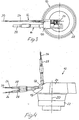
- Fig. 3 is a plan view of a part of the weapon turret according to the invention;
- Fig. 4 is a side view of the weapon turret according to the invention;
- Fig. 5 is a perspective view of the weapons of different calibres mounted pivotably about a common horizontal pivot pin; and
- Fig. 6 is a view similar to Fig. 2, but with an elevation of 0°.
- In Fig. 1, a weapon turret according to the present invention, intended for military vehicles, is denoted in general terms by 10, which weapon turret is equipped with a medium-calibre automatic weapon in the form of an
automatic cannon 12 and a relatively heavy-calibre weapon in the form of a shell launcher 14 (or cannon), in which the twoweapons weapon turret 10 such that they can be jointly pivoted about a commonhorizontal pivot axis 18. Theweapon turret 10 is, in turn, mounted in a vehicle (not shown) pivotably about avertical centre axis 20. Theweapon turret 10 comprises, firstly, alower cage part 22, which accommodates, inter alia, an ammunition magazine for the heavy-calibre weapon 14 and seats for one or more operators and which is mounted in the body of the vehicle rotatably about the saidaxis 20 and, secondly, an upperarmoured turret superstructure 24, which connects to the vehicle body. - In the state shown in Fig. 1, the
barrels weapons barrels axis 18 to an elevation of ca. +85°. This is also shown in side view in Fig. 4. Thebarrels - As shown in greater detail in Fig. 3, the
automatic cannon 12 is fitted in the weapon holder such that thelongitudinal axis 30 of thebarrel 26 extends through thevertical pivot axis 20 of theweapon turret 10. Accordingly, no torsional shocks are suffered by the weapon turret 10 about theaxis 20 during automatic fire, which would otherwise impair the firing accuracy of the automatic cannon in the lateral direction. Improved firing accuracy in the vertical direction is also aided by the fact that thelongitudinal axis 30 of theautomatic cannon 12 also extends through thehorizontal pivot axis 18 for the weapon holder (Fig. 4), no torsional shocks being generated about this axis, which would otherwise disturb the firing accuracy in the vertical direction during automatic fire. Preferably, theweapons pivot axis 18, thereby facilitating manoeuvring of theweapons - The shell launcher 14 (or cannon) is fitted close up to and next to the
automatic cannon 12 and has itsbarrel 28 directed parallel with thebarrel 26 of theautomatic cannon 12. Despite the somewhat asymmetrical fitting of the shell launcher 14 (cannon), its firing accuracy is not affected, since thebarrel 28 has no time to move in the lateral direction during the brief period in which the item of ammunition is present therein during firing but manages to return to the firing position before the next shot is due to be discharged. - As can be seen from Fig. 5, the
barrel 28 of theshell launcher 14 is mounted such that it is axially displaceable in acasing tube 32 fixed in the weapon holder. Arecoil brake 34 is connected to thecasing tube 32 and to aback piece 36 on the rear end of thebarrel 28 and is placed on the bottom side of the rear part of theshell launcher 14. Anadvance mechanism 38, which returns thebarrel 28 to its front position following absorption of the recoil after firing, is likewise connected to thecasing tube 32 and to theback piece 36 on the bottom side of the rear part of theshell launcher 14. Fixed to the top side of thecasing tube 32 are a pair of ammunition guides 40, 42, which have a curvature following the cylindrical outer side of thecasing tube 32 and lead to the ammunition intake of theautomatic cannon 12. These fixed ammunition guides 40, 42 are placed entirely behind thehorizontal pivot axis 18, resulting in minimal vertical motions of the ammunition intake as theautomatic cannon 12 is elevated. This placement of the fixed ammunition guides 40, 42 further facilitates the connection of flexibleammunition feed ducts turret superstructure 24 from a rear-situatedmagazine 48 and allow a rotational and curving motion necessary for a 90° elevation motion of the automatic cannon, as well as motions in the axial direction of theducts casing tube 32 and on the opposite side of this to therecoil brake 34 and theadvance mechanism 38 helps to keep the diameter of a so-calledweapon drum 50, surrounding the weapon holder, small and helps simultaneously to permit a wide range of elevation of theweapons magazine 48, but it can also be stored and fed horizontally. The inlets of the fixed guides 40, 42 can alternatively be inclined at an angle of about half the elevation angle range relative to the longitudinal axis of thebarrel 26 in order to reduce rotation of the ducts during normal elevations. - The
weapon turret 10 is provided with a gyro-stabilizing mechanism (not shown), which makes it possible to fire at targets when the vehicle is in motion.
Claims (8)
- A weapon turret (10) intended for a military vehicle and equipped with a medium-calibre automatic weapon (12), especially an automatic cannon, and a relatively heavy-calibre weapon (14), especially a shell launcher or cannon, in which the two weapons (12, 14) are, firstly, mounted in a weapon holder, fitted in the weapon turret (10), such that they can be jointly pivoted about a common horizontal pivot axis (18) and, secondly, can be pivoted jointly with the turret (10) about a vertical centre axis (20) of the same, the heavy-calibre weapon (14) being mounted next to and parallel with the automatic weapon (12) and close up to this, and in which at least one ammunition magazine (48) in the weapon turret is provided with at least one guide duct (44, 46) for guiding an ammunition belt from the magazine (48) to the automatic weapon (12), characterized in that the automatic weapon (12) is mounted in the weapon holder such that the longitudinal axis (30) of the barrel (26) of the automatic weapon extends through the common horizontal pivot axis (18) and through the vertical centre axis (20) of the weapon turret.
- Weapon turret according to Claim 1, characterized in that the two weapons (12, 14) are jointly pivotable about the horizontal pivot axis (18) in the weapon holder within a range of elevation of ca. -10° to +85°.
- Weapon turret according to Claim 1 or 2, characterized in that the two weapons (12, 14) are mounted in the weapon holder such that their common centre of gravity lies on the horizontal pivot axis (18).
- Weapon turret according to any of Claims 1-3, in which the heavy-calibre weapon (14) is displaceably mounted in a casing tube (32) in the weapon holder and connected to a recoil damper (34) and an advance mechanism (38), characterized in that the recoil damper (34) and the advance mechanism (38) are fitted on the bottom side of the casing tube (32), whilst on the top side of this there is fixedly disposed at least one ammunition guide (40, 42), which follows the curvature of the top side of the casing tube (32) and leads forward to an ammunition intake in the adjoining automatic weapon (12).
- Weapon turret according to Claim 4, characterized in that an ammunition guide duct (44, 46), which is axially expandable and is flexible in every plane, is connected to an inlet of the respective fixed ammunition guide (40, 42).
- Weapon turret according to Claim 5, characterized in that the ammunition magazine (48) is fitted behind the weapons (12, 14) in the weapon turret (10) and in that the flexible ammunition guide duct (44, 46) extends forward from the magazine and is curved such that ammunition in the flexible guide duct (44, 46) can be fed in over the casing tube (32) for the heavy-calibre weapon (14) and into the fixed guide (44, 46) with the ammunition lying substantially horizontally with its front end in the firing direction, the barrel (26) of the automatic weapon having an elevation of 0°.
- Weapon turret according to Claim 5, characterized in that the ammunition magazine (48) is fitted behind the weapons (12, 14) in the weapon turret (10) and in that the flexible ammunition guide duct (44, 46) extends forward from the magazine and is curved such that ammunition in the flexible guide duct can be fed in over the casing tube (32) for the heavy-calibre weapon (14) and into the fixed guide with the ammunition inclined at an angle corresponding to about half the total elevation angle range relative to the barrel (26) of the automatic weapon.
- Weapon turret according to any of Claims 5-7, characterized in that the fixed guide (40, 44) is placed on the casing tube (32) of the heavy-calibre weapon close up to the horizontal pivot axis (18) and on the side thereof which is facing away from the muzzle of the weapon.
Applications Claiming Priority (2)
| Application Number | Priority Date | Filing Date | Title |
|---|---|---|---|
| SE0103095A SE520373C2 (en) | 2001-09-18 | 2001-09-18 | For a military vehicle, the weapon tower is equipped with a medium-caliber automatic weapon and a relatively coarse-caliber weapon. |
| SE0103095 | 2001-09-18 |
Publications (2)
| Publication Number | Publication Date |
|---|---|
| EP1293745A1 EP1293745A1 (en) | 2003-03-19 |
| EP1293745B1 true EP1293745B1 (en) | 2006-03-29 |
Family
ID=20285356
Family Applications (1)
| Application Number | Title | Priority Date | Filing Date |
|---|---|---|---|
| EP02020135A Expired - Lifetime EP1293745B1 (en) | 2001-09-18 | 2002-09-09 | Turret intended for a military vehicle equipped with two weapons |
Country Status (6)
| Country | Link |
|---|---|
| US (1) | US6701821B2 (en) |
| EP (1) | EP1293745B1 (en) |
| AT (1) | ATE321987T1 (en) |
| DE (1) | DE60210182T2 (en) |
| ES (1) | ES2257497T3 (en) |
| SE (1) | SE520373C2 (en) |
Families Citing this family (24)
| Publication number | Priority date | Publication date | Assignee | Title |
|---|---|---|---|---|
| DE10337642B4 (en) * | 2003-08-16 | 2007-08-02 | Kraus-Maffei Wegmann Gmbh & Co. Kg | Modular weapon station, in particular for placement on a combat vehicle |
| US7669513B2 (en) * | 2003-10-09 | 2010-03-02 | Elbit Systems Ltd. | Multiple weapon system for armored vehicle |
| DE102004043711B4 (en) * | 2004-09-09 | 2007-05-31 | Heckler & Koch Gmbh | Freirichtlafette and weapons arrangement with a Freirichtlafette |
| DE102007018507B4 (en) * | 2007-04-19 | 2012-05-03 | Krauss-Maffei Wegmann Gmbh & Co. Kg | Method and apparatus for controlling an assault ammunition launcher |
| DE102007041294B4 (en) * | 2007-08-31 | 2009-12-17 | Rheinmetall Landsysteme Gmbh | ammunition storage |
| FI20075671A7 (en) * | 2007-09-26 | 2009-03-27 | Patria Weapon Systems Oy | Gun tower |
| US9366503B2 (en) * | 2008-04-07 | 2016-06-14 | Foster-Miller, Inc. | Gunshot detection stabilized turret robot |
| ES2351448B1 (en) * | 2009-05-07 | 2012-03-15 | Explosivos Alaveses, S.A. | ABSORPTION SYSTEM OF DIN LOADS? MICAS. |
| DE202009007415U1 (en) | 2009-05-25 | 2010-08-26 | Rheinmetall Waffe Munition Gmbh | Modular weapon carrier |
| IL201051A (en) * | 2009-09-17 | 2016-04-21 | Israel Military Ind | Weapons system |
| US8930066B2 (en) | 2011-01-21 | 2015-01-06 | Control Solutions LLC | Customizable control apparatus and method for a vehicle turret |
| US8428827B2 (en) | 2011-01-21 | 2013-04-23 | Control Solutions LLC | Apparatus and method for controlling rotational movement of a vehicle turret |
| US8607686B2 (en) | 2011-01-21 | 2013-12-17 | Control Solutions LLC | Controlled vehicle turret apparatus and method |
| ITTO20130581A1 (en) * | 2013-07-10 | 2015-01-11 | Oto Melara Spa | TURRET ASSEMBLY, IN PARTICULAR FOR A COMBAT VEHICLE. |
| ITTO20130580A1 (en) * | 2013-07-10 | 2015-01-11 | Oto Melara Spa | TURRET STRUCTURE, IN PARTICULAR FOR A COMBAT VEHICLE. |
| USD792284S1 (en) * | 2013-07-10 | 2017-07-18 | Oto Melara S.P.A. | Turret for a combat vehicle |
| US9194664B1 (en) * | 2015-02-19 | 2015-11-24 | The United States Of America As Represented By The Secretary Of The Army | Main gun shield for battle tank |
| EP3306259A1 (en) | 2016-10-10 | 2018-04-11 | CMI Defence S.A. | Standard, interchangeable structure for an armoured vehicle |
| USD900677S1 (en) * | 2018-04-17 | 2020-11-03 | Fnss Savunma Sistemleri A.S. | Turret |
| SE543680C2 (en) | 2019-10-15 | 2021-06-01 | Bae Systems Haegglunds Ab | Arrangement for feeding ammunition to a weapon |
| SE545474C2 (en) * | 2021-02-26 | 2023-09-26 | Bae Systems Haegglunds Ab | Arrangement of an elevation device for a vehicle mounted weapon system |
| GB2639224A (en) * | 2024-03-12 | 2025-09-17 | Bae Systems Plc | Further improvements to weapon sub-system |
| WO2025191235A1 (en) * | 2024-03-12 | 2025-09-18 | Bae Systems Plc | Weapon sub-system |
| EP4617613A1 (en) * | 2024-03-12 | 2025-09-17 | BAE SYSTEMS plc | Further improvements to weapon sub-system |
Family Cites Families (10)
| Publication number | Priority date | Publication date | Assignee | Title |
|---|---|---|---|---|
| DE2014389C1 (en) * | 1970-03-25 | 1978-04-27 | Rheinstahl Ag, 4300 Essen | Tank turret arranged on an armored vehicle |
| DE2028992C1 (en) * | 1970-06-12 | 1978-04-27 | Thyssen Industrie Ag, 4300 Essen | Arrangement of a barrel weapon in a stabilized gun turret |
| CH596533A5 (en) * | 1976-03-30 | 1978-03-15 | Oerlikon Buehrle Ag | |
| FR2462686A1 (en) * | 1979-07-27 | 1981-02-13 | Hispano Suiza Sa | MILITARY EQUIPMENT COMPRISING A TURRET CARRYING A MAIN EXTERIOR WEAPON |
| US4346644A (en) * | 1980-02-19 | 1982-08-31 | Ares, Inc. | Foldout cradle apparatus for mounting an automatic cannon to a turret exterior |
| DE3207138C2 (en) * | 1982-02-27 | 1987-04-23 | Diehl GmbH & Co, 8500 Nürnberg | Armoured vehicle with a mortar built into the turret |
| US4733596A (en) * | 1987-01-30 | 1988-03-29 | The United States Of America As Represented By The Secretary Of The Army | Add-on missile container for military vehicles |
| US4840108A (en) * | 1987-05-08 | 1989-06-20 | Werkzeugmaschinenfabrick Oerlikon-Buhrle Ag | Apparatus for the infeed of ammunition from an ammunition container to an automatic firing weapon |
| FR2653872B1 (en) * | 1989-10-27 | 1994-05-06 | Etat Francais Delegue Armement | ADJUSTABLE SHOOTING CONDUCT ON A GOGGLE. |
| FR2656683B1 (en) * | 1989-12-28 | 1992-03-27 | Hispano Suiza Sa | TURNER FOR LIGHT SHIELD EQUIPPED WITH A LATERAL WEAPON. |
-
2001
- 2001-09-18 SE SE0103095A patent/SE520373C2/en unknown
-
2002
- 2002-09-09 DE DE60210182T patent/DE60210182T2/en not_active Expired - Fee Related
- 2002-09-09 EP EP02020135A patent/EP1293745B1/en not_active Expired - Lifetime
- 2002-09-09 ES ES02020135T patent/ES2257497T3/en not_active Expired - Lifetime
- 2002-09-09 AT AT02020135T patent/ATE321987T1/en not_active IP Right Cessation
- 2002-09-18 US US10/245,275 patent/US6701821B2/en not_active Expired - Fee Related
Also Published As
| Publication number | Publication date |
|---|---|
| DE60210182D1 (en) | 2006-05-18 |
| DE60210182T2 (en) | 2006-12-28 |
| US6701821B2 (en) | 2004-03-09 |
| ES2257497T3 (en) | 2006-08-01 |
| SE520373C2 (en) | 2003-07-01 |
| ATE321987T1 (en) | 2006-04-15 |
| EP1293745A1 (en) | 2003-03-19 |
| SE0103095L (en) | 2003-03-19 |
| US20030051599A1 (en) | 2003-03-20 |
Similar Documents
| Publication | Publication Date | Title |
|---|---|---|
| US6701821B2 (en) | Weapon turret intended for a military vehicle | |
| US4967642A (en) | Machine gun | |
| US4391179A (en) | Combat vehicle | |
| EP0784778B1 (en) | Ramming system | |
| US3817148A (en) | Cartridge feeding mechanism for firearms | |
| PL197832B1 (en) | Recoil control mechanism for a weapon | |
| US4669357A (en) | Weapon system with barreled weapon in an armored vehicle | |
| US6591733B1 (en) | Loading system | |
| DE50309631D1 (en) | SHOOTING MODULE | |
| US7231863B2 (en) | Arrangement for transferring large-calibre ammunition from an ammunition magazine to loading position in a large-calibre weapon | |
| US3897729A (en) | Cartridge for firearms | |
| US5880395A (en) | Gun turret assembly for an armored vehicle | |
| US8800190B1 (en) | Reciprocating sensory sighting system for a longarm | |
| US5945625A (en) | Tank turret | |
| US3919921A (en) | Hand firearms and ammunition therefor | |
| US7350452B2 (en) | Firearm with improved salvo accuracy and similar device for a firearm | |
| EP0569341B1 (en) | Rammer for a cannon | |
| RU2851861C1 (en) | Grenade launcher installation | |
| CA3052943C (en) | Arrangement for reducing recoiling forces on a sight or other component mounted on a barrel of a weapon | |
| RU2370723C1 (en) | Gun house of armored vehicle | |
| EP0301159B1 (en) | Weapon and ammunition support for cannons | |
| US7513185B1 (en) | Magazine for an automatic weapon | |
| JP2019203669A (en) | Rifle and gun | |
| CA2009417A1 (en) | Rifle | |
| TR2023000242A1 (en) | POWDER MAGAZINE THAT CAN TRANSFER A VARIETY OF MODULE GUNPOWDER |
Legal Events
| Date | Code | Title | Description |
|---|---|---|---|
| PUAI | Public reference made under article 153(3) epc to a published international application that has entered the european phase |
Free format text: ORIGINAL CODE: 0009012 |
|
| AK | Designated contracting states |
Kind code of ref document: A1 Designated state(s): AT BE BG CH CY CZ DE DK EE ES FI FR GB GR IE IT LI LU MC NL PT SE SK TR |
|
| AX | Request for extension of the european patent |
Extension state: AL LT LV MK RO SI |
|
| 17P | Request for examination filed |
Effective date: 20030502 |
|
| RAP1 | Party data changed (applicant data changed or rights of an application transferred) |
Owner name: ALVIS HAEGGLUNDS AB |
|
| AKX | Designation fees paid |
Designated state(s): AT BE BG CH CY CZ DE DK EE ES FI FR GB GR IE IT LI LU MC NL PT SE SK TR |
|
| GRAP | Despatch of communication of intention to grant a patent |
Free format text: ORIGINAL CODE: EPIDOSNIGR1 |
|
| RAP1 | Party data changed (applicant data changed or rights of an application transferred) |
Owner name: LAND SYSTEMS HAEGGLUNDS AKTIEBOLAG |
|
| GRAS | Grant fee paid |
Free format text: ORIGINAL CODE: EPIDOSNIGR3 |
|
| GRAA | (expected) grant |
Free format text: ORIGINAL CODE: 0009210 |
|
| AK | Designated contracting states |
Kind code of ref document: B1 Designated state(s): AT BE BG CH CY CZ DE DK EE ES FI FR GB GR IE IT LI LU MC NL PT SE SK TR |
|
| PG25 | Lapsed in a contracting state [announced via postgrant information from national office to epo] |
Ref country code: NL Free format text: LAPSE BECAUSE OF FAILURE TO SUBMIT A TRANSLATION OF THE DESCRIPTION OR TO PAY THE FEE WITHIN THE PRESCRIBED TIME-LIMIT Effective date: 20060329 |
|
| REG | Reference to a national code |
Ref country code: GB Ref legal event code: FG4D |
|
| REG | Reference to a national code |
Ref country code: CH Ref legal event code: EP |
|
| RAP2 | Party data changed (patent owner data changed or rights of a patent transferred) |
Owner name: BAE SYSTEMS HAEGGLUNDS AKTIEBOLAG |
|
| REG | Reference to a national code |
Ref country code: IE Ref legal event code: FG4D |
|
| REF | Corresponds to: |
Ref document number: 60210182 Country of ref document: DE Date of ref document: 20060518 Kind code of ref document: P |
|
| NLT2 | Nl: modifications (of names), taken from the european patent patent bulletin |
Owner name: BAE SYSTEMS HAEGGLUNDS AKTIEBOLAG Effective date: 20060412 |
|
| PG25 | Lapsed in a contracting state [announced via postgrant information from national office to epo] |
Ref country code: BG Free format text: LAPSE BECAUSE OF FAILURE TO SUBMIT A TRANSLATION OF THE DESCRIPTION OR TO PAY THE FEE WITHIN THE PRESCRIBED TIME-LIMIT Effective date: 20060629 Ref country code: DK Free format text: LAPSE BECAUSE OF FAILURE TO SUBMIT A TRANSLATION OF THE DESCRIPTION OR TO PAY THE FEE WITHIN THE PRESCRIBED TIME-LIMIT Effective date: 20060629 Ref country code: SE Free format text: LAPSE BECAUSE OF FAILURE TO SUBMIT A TRANSLATION OF THE DESCRIPTION OR TO PAY THE FEE WITHIN THE PRESCRIBED TIME-LIMIT Effective date: 20060629 |
|
| REG | Reference to a national code |
Ref country code: GR Ref legal event code: EP Ref document number: 20060401774 Country of ref document: GR Ref country code: CH Ref legal event code: NV Representative=s name: BOVARD AG PATENTANWAELTE |
|
| REG | Reference to a national code |
Ref country code: ES Ref legal event code: FG2A Ref document number: 2257497 Country of ref document: ES Kind code of ref document: T3 |
|
| PG25 | Lapsed in a contracting state [announced via postgrant information from national office to epo] |
Ref country code: PT Free format text: LAPSE BECAUSE OF FAILURE TO SUBMIT A TRANSLATION OF THE DESCRIPTION OR TO PAY THE FEE WITHIN THE PRESCRIBED TIME-LIMIT Effective date: 20060829 |
|
| PG25 | Lapsed in a contracting state [announced via postgrant information from national office to epo] |
Ref country code: MC Free format text: LAPSE BECAUSE OF NON-PAYMENT OF DUE FEES Effective date: 20060930 |
|
| NLV1 | Nl: lapsed or annulled due to failure to fulfill the requirements of art. 29p and 29m of the patents act | ||
| ET | Fr: translation filed | ||
| PLBE | No opposition filed within time limit |
Free format text: ORIGINAL CODE: 0009261 |
|
| STAA | Information on the status of an ep patent application or granted ep patent |
Free format text: STATUS: NO OPPOSITION FILED WITHIN TIME LIMIT |
|
| 26N | No opposition filed |
Effective date: 20070102 |
|
| PGFP | Annual fee paid to national office [announced via postgrant information from national office to epo] |
Ref country code: ES Payment date: 20070917 Year of fee payment: 6 Ref country code: IE Payment date: 20070917 Year of fee payment: 6 |
|
| PGFP | Annual fee paid to national office [announced via postgrant information from national office to epo] |
Ref country code: DE Payment date: 20070924 Year of fee payment: 6 |
|
| PGFP | Annual fee paid to national office [announced via postgrant information from national office to epo] |
Ref country code: AT Payment date: 20070924 Year of fee payment: 6 Ref country code: CH Payment date: 20070914 Year of fee payment: 6 Ref country code: FI Payment date: 20070906 Year of fee payment: 6 Ref country code: SK Payment date: 20070907 Year of fee payment: 6 Ref country code: TR Payment date: 20070903 Year of fee payment: 6 |
|
| PGFP | Annual fee paid to national office [announced via postgrant information from national office to epo] |
Ref country code: CZ Payment date: 20070905 Year of fee payment: 6 Ref country code: GB Payment date: 20070918 Year of fee payment: 6 |
|
| PGFP | Annual fee paid to national office [announced via postgrant information from national office to epo] |
Ref country code: BE Payment date: 20070924 Year of fee payment: 6 Ref country code: IT Payment date: 20070915 Year of fee payment: 6 |
|
| PGFP | Annual fee paid to national office [announced via postgrant information from national office to epo] |
Ref country code: FR Payment date: 20070831 Year of fee payment: 6 |
|
| PGFP | Annual fee paid to national office [announced via postgrant information from national office to epo] |
Ref country code: GR Payment date: 20070927 Year of fee payment: 6 |
|
| PG25 | Lapsed in a contracting state [announced via postgrant information from national office to epo] |
Ref country code: EE Free format text: LAPSE BECAUSE OF FAILURE TO SUBMIT A TRANSLATION OF THE DESCRIPTION OR TO PAY THE FEE WITHIN THE PRESCRIBED TIME-LIMIT Effective date: 20060329 |
|
| PG25 | Lapsed in a contracting state [announced via postgrant information from national office to epo] |
Ref country code: LU Free format text: LAPSE BECAUSE OF NON-PAYMENT OF DUE FEES Effective date: 20060909 |
|
| PG25 | Lapsed in a contracting state [announced via postgrant information from national office to epo] |
Ref country code: CY Free format text: LAPSE BECAUSE OF FAILURE TO SUBMIT A TRANSLATION OF THE DESCRIPTION OR TO PAY THE FEE WITHIN THE PRESCRIBED TIME-LIMIT Effective date: 20060329 |
|
| BERE | Be: lapsed |
Owner name: *BAE SYSTEMS HAGGLUNDS A.B. Effective date: 20080930 |
|
| REG | Reference to a national code |
Ref country code: CH Ref legal event code: PL |
|
| GBPC | Gb: european patent ceased through non-payment of renewal fee |
Effective date: 20080909 |
|
| PG25 | Lapsed in a contracting state [announced via postgrant information from national office to epo] |
Ref country code: CZ Free format text: LAPSE BECAUSE OF NON-PAYMENT OF DUE FEES Effective date: 20080909 Ref country code: FI Free format text: LAPSE BECAUSE OF NON-PAYMENT OF DUE FEES Effective date: 20080909 |
|
| REG | Reference to a national code |
Ref country code: FR Ref legal event code: ST Effective date: 20090529 |
|
| PG25 | Lapsed in a contracting state [announced via postgrant information from national office to epo] |
Ref country code: BE Free format text: LAPSE BECAUSE OF NON-PAYMENT OF DUE FEES Effective date: 20080930 Ref country code: IE Free format text: LAPSE BECAUSE OF NON-PAYMENT OF DUE FEES Effective date: 20080909 |
|
| PG25 | Lapsed in a contracting state [announced via postgrant information from national office to epo] |
Ref country code: AT Free format text: LAPSE BECAUSE OF NON-PAYMENT OF DUE FEES Effective date: 20080909 Ref country code: DE Free format text: LAPSE BECAUSE OF NON-PAYMENT OF DUE FEES Effective date: 20090401 Ref country code: IT Free format text: LAPSE BECAUSE OF NON-PAYMENT OF DUE FEES Effective date: 20080909 |
|
| PG25 | Lapsed in a contracting state [announced via postgrant information from national office to epo] |
Ref country code: SK Free format text: LAPSE BECAUSE OF NON-PAYMENT OF DUE FEES Effective date: 20080909 |
|
| PG25 | Lapsed in a contracting state [announced via postgrant information from national office to epo] |
Ref country code: FR Free format text: LAPSE BECAUSE OF NON-PAYMENT OF DUE FEES Effective date: 20080930 Ref country code: CH Free format text: LAPSE BECAUSE OF NON-PAYMENT OF DUE FEES Effective date: 20080930 Ref country code: LI Free format text: LAPSE BECAUSE OF NON-PAYMENT OF DUE FEES Effective date: 20080930 |
|
| REG | Reference to a national code |
Ref country code: ES Ref legal event code: FD2A Effective date: 20080910 |
|
| PG25 | Lapsed in a contracting state [announced via postgrant information from national office to epo] |
Ref country code: GB Free format text: LAPSE BECAUSE OF NON-PAYMENT OF DUE FEES Effective date: 20080909 Ref country code: GR Free format text: LAPSE BECAUSE OF NON-PAYMENT OF DUE FEES Effective date: 20090402 |
|
| PG25 | Lapsed in a contracting state [announced via postgrant information from national office to epo] |
Ref country code: ES Free format text: LAPSE BECAUSE OF NON-PAYMENT OF DUE FEES Effective date: 20080910 |
|
| PG25 | Lapsed in a contracting state [announced via postgrant information from national office to epo] |
Ref country code: TR Free format text: LAPSE BECAUSE OF NON-PAYMENT OF DUE FEES Effective date: 20100917 |
|
| PG25 | Lapsed in a contracting state [announced via postgrant information from national office to epo] |
Ref country code: TR Free format text: LAPSE BECAUSE OF NON-PAYMENT OF DUE FEES Effective date: 20080909 |