EP1293742A2 - Abgaswärmeübertrager - Google Patents
Abgaswärmeübertrager Download PDFInfo
- Publication number
- EP1293742A2 EP1293742A2 EP02017055A EP02017055A EP1293742A2 EP 1293742 A2 EP1293742 A2 EP 1293742A2 EP 02017055 A EP02017055 A EP 02017055A EP 02017055 A EP02017055 A EP 02017055A EP 1293742 A2 EP1293742 A2 EP 1293742A2
- Authority
- EP
- European Patent Office
- Prior art keywords
- exhaust gas
- heat exchanger
- exhaust
- exchanger according
- mixing device
- Prior art date
- Legal status (The legal status is an assumption and is not a legal conclusion. Google has not performed a legal analysis and makes no representation as to the accuracy of the status listed.)
- Granted
Links
Images

Classifications
-
- B—PERFORMING OPERATIONS; TRANSPORTING
- B01—PHYSICAL OR CHEMICAL PROCESSES OR APPARATUS IN GENERAL
- B01F—MIXING, e.g. DISSOLVING, EMULSIFYING OR DISPERSING
- B01F25/00—Flow mixers; Mixers for falling materials, e.g. solid particles
- B01F25/40—Static mixers
- B01F25/42—Static mixers in which the mixing is affected by moving the components jointly in changing directions, e.g. in tubes provided with baffles or obstructions
- B01F25/43—Mixing tubes, e.g. wherein the material is moved in a radial or partly reversed direction
- B01F25/431—Straight mixing tubes with baffles or obstructions that do not cause substantial pressure drop; Baffles therefor
- B01F25/4316—Straight mixing tubes with baffles or obstructions that do not cause substantial pressure drop; Baffles therefor the baffles being flat pieces of material, e.g. intermeshing, fixed to the wall or fixed on a central rod
-
- F—MECHANICAL ENGINEERING; LIGHTING; HEATING; WEAPONS; BLASTING
- F01—MACHINES OR ENGINES IN GENERAL; ENGINE PLANTS IN GENERAL; STEAM ENGINES
- F01N—GAS-FLOW SILENCERS OR EXHAUST APPARATUS FOR MACHINES OR ENGINES IN GENERAL; GAS-FLOW SILENCERS OR EXHAUST APPARATUS FOR INTERNAL-COMBUSTION ENGINES
- F01N3/00—Exhaust or silencing apparatus having means for purifying, rendering innocuous, or otherwise treating exhaust
- F01N3/08—Exhaust or silencing apparatus having means for purifying, rendering innocuous, or otherwise treating exhaust for rendering innocuous
- F01N3/0807—Exhaust or silencing apparatus having means for purifying, rendering innocuous, or otherwise treating exhaust for rendering innocuous by using absorbents or adsorbents
- F01N3/0814—Exhaust or silencing apparatus having means for purifying, rendering innocuous, or otherwise treating exhaust for rendering innocuous by using absorbents or adsorbents combined with catalytic converters, e.g. NOx absorption/storage reduction catalysts
-
- B—PERFORMING OPERATIONS; TRANSPORTING
- B01—PHYSICAL OR CHEMICAL PROCESSES OR APPARATUS IN GENERAL
- B01F—MIXING, e.g. DISSOLVING, EMULSIFYING OR DISPERSING
- B01F23/00—Mixing according to the phases to be mixed, e.g. dispersing or emulsifying
- B01F23/10—Mixing gases with gases
-
- F—MECHANICAL ENGINEERING; LIGHTING; HEATING; WEAPONS; BLASTING
- F01—MACHINES OR ENGINES IN GENERAL; ENGINE PLANTS IN GENERAL; STEAM ENGINES
- F01N—GAS-FLOW SILENCERS OR EXHAUST APPARATUS FOR MACHINES OR ENGINES IN GENERAL; GAS-FLOW SILENCERS OR EXHAUST APPARATUS FOR INTERNAL-COMBUSTION ENGINES
- F01N3/00—Exhaust or silencing apparatus having means for purifying, rendering innocuous, or otherwise treating exhaust
- F01N3/08—Exhaust or silencing apparatus having means for purifying, rendering innocuous, or otherwise treating exhaust for rendering innocuous
- F01N3/10—Exhaust or silencing apparatus having means for purifying, rendering innocuous, or otherwise treating exhaust for rendering innocuous by thermal or catalytic conversion of noxious components of exhaust
- F01N3/24—Exhaust or silencing apparatus having means for purifying, rendering innocuous, or otherwise treating exhaust for rendering innocuous by thermal or catalytic conversion of noxious components of exhaust characterised by constructional aspects of converting apparatus
- F01N3/28—Construction of catalytic reactors
- F01N3/2882—Catalytic reactors combined or associated with other devices, e.g. exhaust silencers or other exhaust purification devices
-
- F—MECHANICAL ENGINEERING; LIGHTING; HEATING; WEAPONS; BLASTING
- F01—MACHINES OR ENGINES IN GENERAL; ENGINE PLANTS IN GENERAL; STEAM ENGINES
- F01N—GAS-FLOW SILENCERS OR EXHAUST APPARATUS FOR MACHINES OR ENGINES IN GENERAL; GAS-FLOW SILENCERS OR EXHAUST APPARATUS FOR INTERNAL-COMBUSTION ENGINES
- F01N5/00—Exhaust or silencing apparatus combined or associated with devices profiting by exhaust energy
- F01N5/02—Exhaust or silencing apparatus combined or associated with devices profiting by exhaust energy the devices using heat
-
- F—MECHANICAL ENGINEERING; LIGHTING; HEATING; WEAPONS; BLASTING
- F28—HEAT EXCHANGE IN GENERAL
- F28D—HEAT-EXCHANGE APPARATUS, NOT PROVIDED FOR IN ANOTHER SUBCLASS, IN WHICH THE HEAT-EXCHANGE MEDIA DO NOT COME INTO DIRECT CONTACT
- F28D7/00—Heat-exchange apparatus having stationary tubular conduit assemblies for both heat-exchange media, the media being in contact with different sides of a conduit wall
- F28D7/16—Heat-exchange apparatus having stationary tubular conduit assemblies for both heat-exchange media, the media being in contact with different sides of a conduit wall the conduits being arranged in parallel spaced relation
-
- F—MECHANICAL ENGINEERING; LIGHTING; HEATING; WEAPONS; BLASTING
- F28—HEAT EXCHANGE IN GENERAL
- F28F—DETAILS OF HEAT-EXCHANGE AND HEAT-TRANSFER APPARATUS, OF GENERAL APPLICATION
- F28F13/00—Arrangements for modifying heat-transfer, e.g. increasing, decreasing
- F28F13/06—Arrangements for modifying heat-transfer, e.g. increasing, decreasing by affecting the pattern of flow of the heat-exchange media
- F28F13/12—Arrangements for modifying heat-transfer, e.g. increasing, decreasing by affecting the pattern of flow of the heat-exchange media by creating turbulence, e.g. by stirring, by increasing the force of circulation
-
- F—MECHANICAL ENGINEERING; LIGHTING; HEATING; WEAPONS; BLASTING
- F01—MACHINES OR ENGINES IN GENERAL; ENGINE PLANTS IN GENERAL; STEAM ENGINES
- F01N—GAS-FLOW SILENCERS OR EXHAUST APPARATUS FOR MACHINES OR ENGINES IN GENERAL; GAS-FLOW SILENCERS OR EXHAUST APPARATUS FOR INTERNAL-COMBUSTION ENGINES
- F01N2240/00—Combination or association of two or more different exhaust treating devices, or of at least one such device with an auxiliary device, not covered by indexing codes F01N2230/00 or F01N2250/00, one of the devices being
- F01N2240/02—Combination or association of two or more different exhaust treating devices, or of at least one such device with an auxiliary device, not covered by indexing codes F01N2230/00 or F01N2250/00, one of the devices being a heat exchanger
-
- F—MECHANICAL ENGINEERING; LIGHTING; HEATING; WEAPONS; BLASTING
- F28—HEAT EXCHANGE IN GENERAL
- F28D—HEAT-EXCHANGE APPARATUS, NOT PROVIDED FOR IN ANOTHER SUBCLASS, IN WHICH THE HEAT-EXCHANGE MEDIA DO NOT COME INTO DIRECT CONTACT
- F28D21/00—Heat-exchange apparatus not covered by any of the groups F28D1/00 - F28D20/00
- F28D21/0001—Recuperative heat exchangers
- F28D21/0003—Recuperative heat exchangers the heat being recuperated from exhaust gases
-
- Y—GENERAL TAGGING OF NEW TECHNOLOGICAL DEVELOPMENTS; GENERAL TAGGING OF CROSS-SECTIONAL TECHNOLOGIES SPANNING OVER SEVERAL SECTIONS OF THE IPC; TECHNICAL SUBJECTS COVERED BY FORMER USPC CROSS-REFERENCE ART COLLECTIONS [XRACs] AND DIGESTS
- Y02—TECHNOLOGIES OR APPLICATIONS FOR MITIGATION OR ADAPTATION AGAINST CLIMATE CHANGE
- Y02A—TECHNOLOGIES FOR ADAPTATION TO CLIMATE CHANGE
- Y02A50/00—TECHNOLOGIES FOR ADAPTATION TO CLIMATE CHANGE in human health protection, e.g. against extreme weather
- Y02A50/20—Air quality improvement or preservation, e.g. vehicle emission control or emission reduction by using catalytic converters
-
- Y—GENERAL TAGGING OF NEW TECHNOLOGICAL DEVELOPMENTS; GENERAL TAGGING OF CROSS-SECTIONAL TECHNOLOGIES SPANNING OVER SEVERAL SECTIONS OF THE IPC; TECHNICAL SUBJECTS COVERED BY FORMER USPC CROSS-REFERENCE ART COLLECTIONS [XRACs] AND DIGESTS
- Y02—TECHNOLOGIES OR APPLICATIONS FOR MITIGATION OR ADAPTATION AGAINST CLIMATE CHANGE
- Y02T—CLIMATE CHANGE MITIGATION TECHNOLOGIES RELATED TO TRANSPORTATION
- Y02T10/00—Road transport of goods or passengers
- Y02T10/10—Internal combustion engine [ICE] based vehicles
- Y02T10/12—Improving ICE efficiencies
Definitions
- the invention relates to an exhaust gas heat exchanger according to the preamble of claim 1.
- DE 199 62 863 A1 discloses an exhaust gas heat exchanger for transmission of heat between the exhaust gas of an internal combustion engine of a motor vehicle and a coolant having a housing with a Exhaust inlet opening and an exhaust gas outlet opening and an exhaust gas inlet region and an exhaust gas exit area and in between one Heat transfer area encloses.
- a the Heat transfer associated with a partial flow of the Exhaust gas flowed through bypass channel integrated, opposite to the Coolant is thermally insulated.
- the bypass channel is this opposite the Heat transfer area sealed fluid-tight by a partition.
- the two partial flows of the exhaust gas are in the end region of the exhaust gas heat exchanger merged.
- the exhaust gas heat exchanger takes place in the case of a division of the exhaust gas stream in the exhaust gas heat exchanger, a part through the exhaust gas cooler and the other part flows through the bypass, a faster mixture of the the exhaust heat exchanger exhaust gas flowing out, so that, for example, a subsequently arranged NOx catalyst in a direct injection Otto engine or possibly also in a regulated exhaust gas recirculation uniformly tempered exhaust gas can be added or returned. Further a more precise regulation of the exhaust gas temperature can take place.
- the mixing device is directly in the Exhaust gas heat exchanger integrated, ie directly in the housing thereof arranged.
- the mixing device swirls two partial streams of the exhaust gas with one another, wherein a partial flow of the exhaust gas has previously flowed through the exhaust gas cooler, i.e. is cooled and the other part flow has flowed through the bypass, i. is essentially uncooled. At whirling arise preferential two or more counter-rotating swirls.
- the mixing device has at least two obliquely to Flow direction of the exhaust gas arranged areas.
- the areas are preferably formed by a plate which is a transversely to the Flow direction of the exhaust gas axis is bent.
- the areas engage in each other several times.
- the areas have the shape at least one two-pronged fork.
- the Tines of the fork flows around first by the flowing exhaust gas.
- the mixing device comprises three plates, wherein the plates have areas which are oblique to the Direction of flow are aligned.
- the plates can also be more or, at appropriate design, fewer plates may be provided.
- the regions are arranged such that the flow of the Exhaust gas forms two or more oppositely rotating vortices, the each a partial flow of the cooled and by the bypass streamed, uncooled exhaust gas include.
- the plates are plugged into each other, for what appropriate Slots are provided in the plates.
- the exhaust pipe 1 shown in Fig. 1 has the engine (not shown) Coming a precatalyst 2, an exhaust heat exchanger 3 with a Housing 4 of substantially 8-cornered cross section, two exhaust valves 5 for controlling the exhaust gas flow through a bypass 6 and / or 14 Winglet tubes 7, in which the exhaust gas can be cooled, and one on the bypass 6 and the winglet tubes 7 following mixing device 8, as well a subsequently arranged NOx storage catalytic converter 9.
- the exhaust gas flows as needed the flowed through by a coolant winglet tubes 7 for cooling or Heating the exhaust gas passed or substantially without Temperature change is passed through the bypass 6, so it with a predetermined temperature of the subsequently arranged NOx catalyst 9 is supplied, which can then work in the optimum range.
- the mixing device. 8 serves to mix the two Partial flows of the exhaust gas, giving a homogeneous temperature distribution results in the lowest possible pressure loss.
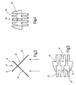
- the mixing device 8 a plate 12 provided with slots 11 and narrow cuts 11 ' on, which is bent in the middle almost at a right angle, so that in the essentially two subregions 13 arise.
- These are individual thighs 14 of the portions 13 are not bent and cross legs 14 of the other sub-area 13.
- the two sub-areas 13 have substantially the shape of several juxtaposed two-pronged forks whose stems form the legs 14. Due to lack of space due to the forks on Edge of the outer tines.
- the plate 12 is in turn so in Exhaust heat exchanger 3 arranged that each portion 13 of the plate 12 is aligned at an angle of approximately 45 ° to the flow direction.
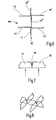
- the mixing device 108 is formed by three plates 112.
- the plates 112 have portions 113 which are slightly transverse to one another Flow direction arranged axis are bent.
- the single ones Subareas 113 are each with respect to the crossing points of the individual Plates 112 bent in different directions so that all Subareas 113 'around the first crossing point in the clockwise direction and all Subareas 113 "about the second intersection point opposite Are bent clockwise.
- the differently tempered partial flows of the exhaust gas arrive first to the regions of the plates 112 arranged in the direction of flow, arriving at different sides of the longer plate 112 ".
- Subareas 113 the two partial streams are each divided in the middle and swirled, so that it comes to a mixing of the two partial streams.
Landscapes
- Engineering & Computer Science (AREA)
- Chemical & Material Sciences (AREA)
- Chemical Kinetics & Catalysis (AREA)
- Mechanical Engineering (AREA)
- General Engineering & Computer Science (AREA)
- Combustion & Propulsion (AREA)
- Physics & Mathematics (AREA)
- Thermal Sciences (AREA)
- Dispersion Chemistry (AREA)
- Health & Medical Sciences (AREA)
- Toxicology (AREA)
- Exhaust Gas After Treatment (AREA)
- Exhaust Silencers (AREA)
- Gas Separation By Absorption (AREA)
- Separation By Low-Temperature Treatments (AREA)
Abstract
Description
- Fig. 1
- einen schematisch dargestellten Abschnitt der Abgasleitung vom Motor ausgehend mit einem Abgaswärmeübertrager samt Mischvorrichtung gemäß dem ersten Ausführungsbeispiel,
- Fig. 2
- eine teilweise geschnitten dargestellte Ansicht der Mischvorrichtung von Fig. 1,
- Fig. 3
- eine Seitenansicht der Mischvorrichtung von Fig. 1,
- Fig. 4
- eine weitere Seitenansicht der Mischvorrichtung von Fig. 1,
- Fig. 5
- eine Ansicht entgegen der Strömungsrichtung der Mischvorrichtung von Fig. 1
- Fig. 6
- eine Ansicht entgegen der Strömungsrichtung der Mischvorrichtung gemäß dem zweiten Ausführungsbeispiel,
- Fig. 7
- eine Seitenansicht der Mischvorrichtung in Richtung des Pfeils VII von Fig. 6 und
- Fig. 8
- eine isometrische Ansicht der Mischvorrichtung von Fig. 6.
Claims (10)
- Abgaswärmeübertrager (3) zur Übertragung von Wärme zwischen dem Abgas einer Brennkraftmaschine eines Kraftfahrzeugs und einem Kühlmittel, mit einem Gehäuse (4), das eine Abgaseintrittsöffnung und eine Abgasaustrittsöffnung und einen Wärmeübertragungsbereich umschließt, wobei im Gehäuse (4) ein von zumindest einem Teilstrom des Abgases durchströmbarer Bypass (6) integriert ist, der gegenüber dem Kühlmittel thermisch isoliert ist, dadurch gekennzeichnet, dass der Abgaswärmeübertrager (1) eine Mischvorrichtung (8; 108) aufweist.
- Abgaswärmeübertrager nach Anspruch 1, dadurch gekennzeichnet, dass die Mischvorrichtung (8; 108) in das Gehäuse (4) des Abgaswärmeübertragers (1) integriert ist.
- Abgaswärmeübertrager nach Anspruch 2, dadurch gekennzeichnet, dass die Mischvorrichtung (8; 108) zwei Teilströme des Abgases miteinander verwirbelt.
- Abgaswärmeübertrager nach einem der vorstehenden Ansprüche, dadurch gekennzeichnet, dass die Mischvorrichtung (8; 108) mindestens zwei schräg zur Strömungsrichtung des Abgases angeordnete Bereiche (13; 113) aufweist.
- Abgaswärmeübertrager nach einem der vorstehenden Ansprüche, dadurch gekennzeichnet, dass zwei schräg zur Strömungsrichtung angeordnete Bereiche (13) aufweist, die mehrfach ineinander greifen.
- Abgaswärmeübertrager nach Anspruch 5, dadurch gekennzeichnet, dass die Bereiche (13) die Gestalt mindestens einer zweizinkigen Gabel aufweisen.
- Abgaswärmeübertrager nach Anspruch 6, dadurch gekennzeichnet, dass die Zinken der Gabel vom durchströmenden Abgas zuerst umströmt werden.
- Abgaswärmeübertrager nach einem der Ansprüche 1 bis 4, dadurch gekennzeichnet, dass die Mischvorrichtung (108) drei Platten (112) umfasst, wobei die Platten Bereiche (113) aufweisen, die schräg zur Strömungsrichtung ausgerichtet sind.
- Abgaswärmeübertrager nach Anspruch 8, dadurch gekennzeichnet, dass die Bereiche (113) derart angeordnet sind, dass die Strömung des Abgases zwei entgegengesetzt drehende Wirbel bildet, die jeweils einen Teilstrom des gekühlten und des durch den Bypass (6) geströmten, ungekühlten Abgases umfassen.
- Abgaswärmeübertrager nach einem der Ansprüche 8 bis 9, dadurch gekennzeichnet, dass die Platten (112) ineinander gesteckt sind.
Applications Claiming Priority (2)
| Application Number | Priority Date | Filing Date | Title |
|---|---|---|---|
| DE10144827 | 2001-09-12 | ||
| DE10144827A DE10144827A1 (de) | 2001-09-12 | 2001-09-12 | Abgaswärmeübertrager |
Publications (3)
| Publication Number | Publication Date |
|---|---|
| EP1293742A2 true EP1293742A2 (de) | 2003-03-19 |
| EP1293742A3 EP1293742A3 (de) | 2004-06-30 |
| EP1293742B1 EP1293742B1 (de) | 2006-04-26 |
Family
ID=7698711
Family Applications (1)
| Application Number | Title | Priority Date | Filing Date |
|---|---|---|---|
| EP02017055A Expired - Lifetime EP1293742B1 (de) | 2001-09-12 | 2002-07-27 | Abgaswärmeübertrager |
Country Status (3)
| Country | Link |
|---|---|
| EP (1) | EP1293742B1 (de) |
| AT (1) | ATE324564T1 (de) |
| DE (2) | DE10144827A1 (de) |
Cited By (5)
| Publication number | Priority date | Publication date | Assignee | Title |
|---|---|---|---|---|
| WO2005059466A1 (en) * | 2003-12-11 | 2005-06-30 | Utc Power, Llc. | High-efficiency turbulators for high-stage generator of absorption chiller/heater |
| DE102005006055A1 (de) * | 2005-02-10 | 2006-08-24 | Medartis Ag | Wärmetauscher |
| DE102005042314A1 (de) * | 2005-09-06 | 2007-03-08 | Behr Gmbh & Co. Kg | Wärmetauscher |
| EP1367253B2 (de) † | 2002-05-28 | 2010-06-16 | Dayco Ensa, S.L. | Wärmeaustauscher für ein EGR System mit integrierter Bypassleitung |
| EP4484881A1 (de) * | 2023-06-28 | 2025-01-01 | RTX Corporation | Wärmetauscher mit verbessertem wärmeübertragungsverteiler |
Families Citing this family (5)
| Publication number | Priority date | Publication date | Assignee | Title |
|---|---|---|---|---|
| DE10247837A1 (de) | 2002-10-14 | 2004-04-22 | Behr Gmbh & Co. | Wärmeübertrager |
| DE102007019878A1 (de) * | 2007-04-25 | 2008-11-06 | J. Eberspächer GmbH & Co. KG | Misch- und/oder Verdampfungseinrichtung und zugehöriges Herstellungsverfahren |
| DE102007028449A1 (de) * | 2007-04-25 | 2008-10-30 | J. Eberspächer GmbH & Co. KG | Misch- und/oder Verdampfungseinrichtung und zugehöriges Herstellungsverfahren |
| DE102008014170A1 (de) | 2007-05-30 | 2008-12-04 | Behr Gmbh & Co. Kg | Wärmetauscher und Baueinheit mit einem Wärmetauscher |
| DE102015200024B4 (de) | 2014-01-24 | 2023-03-23 | Ford Global Technologies, Llc | Niederdruckabgasrückführung mit Stickoxidspeicherkatalysator |
Citations (1)
| Publication number | Priority date | Publication date | Assignee | Title |
|---|---|---|---|---|
| DE19962863A1 (de) | 1999-12-24 | 2001-06-28 | Behr Gmbh & Co | Wärmeübertrager |
Family Cites Families (9)
| Publication number | Priority date | Publication date | Assignee | Title |
|---|---|---|---|---|
| US4179222A (en) * | 1978-01-11 | 1979-12-18 | Systematix Controls, Inc. | Flow turbulence generating and mixing device |
| HU179455B (en) * | 1979-07-16 | 1982-10-28 | Energiagazdalkodasi Intezet | Ribbed device improving the heat transfer composed from sheet strips |
| DE3039742A1 (de) * | 1980-10-22 | 1982-05-27 | Motoren-Werke Mannheim AG vorm. Benz Abt. stationärer Motorenbau, 6800 Mannheim | Abgas-waermeuebertrager, insbesondere fuer kleine verbrennungsmotoren mit abwaermeverwertung |
| DD269073A3 (de) * | 1987-04-23 | 1989-06-21 | Energie & Transportforsch Inst | Wirbelbleche fuer waermeuebertrager |
| DE3828034A1 (de) * | 1988-08-18 | 1990-02-22 | Borsig Gmbh | Waermetauscher |
| DE4109435C1 (en) * | 1991-03-22 | 1992-05-27 | Mercedes-Benz Aktiengesellschaft, 7000 Stuttgart, De | Piston IC engine working temp. booster - has heating air heat exchanger passed by combustion gas or gases of separate burner |
| DE9406197U1 (de) * | 1994-04-14 | 1994-06-16 | Behr Gmbh & Co | Wärmetauscher zum Kühlen von Abgas eines Kraftfahrzeugmotors |
| DE19540683A1 (de) * | 1995-11-01 | 1997-05-07 | Behr Gmbh & Co | Wärmeüberträger zum Kühlen von Abgas |
| DE10014266A1 (de) * | 2000-03-22 | 2001-09-27 | Zeuna Staerker Kg | Luftgekühlter Abgaskühler für ein verbrennungsmotorisch angetriebenes Kraftfahrzeug |
-
2001
- 2001-09-12 DE DE10144827A patent/DE10144827A1/de not_active Withdrawn
-
2002
- 2002-07-27 EP EP02017055A patent/EP1293742B1/de not_active Expired - Lifetime
- 2002-07-27 DE DE50206536T patent/DE50206536D1/de not_active Expired - Lifetime
- 2002-07-27 AT AT02017055T patent/ATE324564T1/de not_active IP Right Cessation
Patent Citations (1)
| Publication number | Priority date | Publication date | Assignee | Title |
|---|---|---|---|---|
| DE19962863A1 (de) | 1999-12-24 | 2001-06-28 | Behr Gmbh & Co | Wärmeübertrager |
Cited By (9)
| Publication number | Priority date | Publication date | Assignee | Title |
|---|---|---|---|---|
| EP1367253B2 (de) † | 2002-05-28 | 2010-06-16 | Dayco Ensa, S.L. | Wärmeaustauscher für ein EGR System mit integrierter Bypassleitung |
| WO2005059466A1 (en) * | 2003-12-11 | 2005-06-30 | Utc Power, Llc. | High-efficiency turbulators for high-stage generator of absorption chiller/heater |
| US7117686B2 (en) | 2003-12-11 | 2006-10-10 | Utc Power, Llc | High-efficiency turbulators for high-stage generator of absorption chiller/heater |
| US7275393B2 (en) | 2003-12-11 | 2007-10-02 | Utc Power, Llc | High-efficiency turbulators for high-stage generator of absorption chiller/heater |
| DE102005006055A1 (de) * | 2005-02-10 | 2006-08-24 | Medartis Ag | Wärmetauscher |
| DE102005006055B4 (de) * | 2005-02-10 | 2015-07-23 | Albert Handtmann Metallgusswerk Gmbh & Co. Kg | Wärmetauscher |
| DE102005042314A1 (de) * | 2005-09-06 | 2007-03-08 | Behr Gmbh & Co. Kg | Wärmetauscher |
| EP4484881A1 (de) * | 2023-06-28 | 2025-01-01 | RTX Corporation | Wärmetauscher mit verbessertem wärmeübertragungsverteiler |
| US12650274B2 (en) | 2023-06-28 | 2026-06-09 | Rtx Corporation | Heat exchanger with enhanced heat transfer manifold |
Also Published As
| Publication number | Publication date |
|---|---|
| DE10144827A1 (de) | 2003-03-27 |
| EP1293742B1 (de) | 2006-04-26 |
| EP1293742A3 (de) | 2004-06-30 |
| ATE324564T1 (de) | 2006-05-15 |
| DE50206536D1 (de) | 2006-06-01 |
Similar Documents
| Publication | Publication Date | Title |
|---|---|---|
| DE19511991C2 (de) | Plattenwärmetauscher | |
| EP1132609B1 (de) | Abgaswärmetauscher in einer Abgasrückführungsanordnung | |
| DE102018106286B4 (de) | Nachbehandlungssystem | |
| EP1985953B1 (de) | Wärmetauscher, insbesondere zur Abgaskühlung, Verfahren zum Betreiben eines solchen Wärmetauschers und System mit einem Abgaskühler | |
| EP1994349B1 (de) | Wärmeübertragungseinheit | |
| DE69606633T2 (de) | Statische vorrichtung zur strömungsdurchmischung von fluiden | |
| DE10139424B4 (de) | Abgasanlage eines Kraftfahrzeugs | |
| EP1901020B1 (de) | Stapelscheibenwärmetauscher zur Ladeluftkühlung | |
| DE102009030963A1 (de) | Einrichtung und Verfahren zum Kühlen eines Abgases | |
| DE3017701A1 (de) | Waermetauscher fuer mehrere stroemungsmittel | |
| EP1941224A1 (de) | Wärmetauscher | |
| DE4220672C2 (de) | Kühleranordnung | |
| DE2438845B2 (de) | ||
| EP1293742B1 (de) | Abgaswärmeübertrager | |
| EP2025911A1 (de) | Abgaskühlvorrichtung für eine Verbrennungskraftmaschine | |
| DE10328846C5 (de) | Wärmetauscher | |
| EP1288603B1 (de) | Abgaswärmeübertrager | |
| EP1532359B1 (de) | Zylinderkopf für eine wassergekühlte mehrzylindrige brennkraftmaschine | |
| DE10061949A1 (de) | Abgas-Wärmetauscher | |
| DE102005045103B3 (de) | Kühlvorrichtung für eine Verbrennungskraftmaschine | |
| DE102006049106A1 (de) | Wärmetauscher | |
| EP3039372A1 (de) | Wärmeübertrager | |
| EP1687579B1 (de) | Ladeluft-/kühlmittel-kühler | |
| EP1687580B1 (de) | Ladeluft-/kühlmittel-kühler | |
| DE2306426A1 (de) | Waermetauscher |
Legal Events
| Date | Code | Title | Description |
|---|---|---|---|
| PUAI | Public reference made under article 153(3) epc to a published international application that has entered the european phase |
Free format text: ORIGINAL CODE: 0009012 |
|
| AK | Designated contracting states |
Kind code of ref document: A2 Designated state(s): AT BE BG CH CY CZ DE DK EE ES FI FR GB GR IE IT LI LU MC NL PT SE SK TR |
|
| AX | Request for extension of the european patent |
Extension state: AL LT LV MK RO SI |
|
| PUAL | Search report despatched |
Free format text: ORIGINAL CODE: 0009013 |
|
| AK | Designated contracting states |
Kind code of ref document: A3 Designated state(s): AT BE BG CH CY CZ DE DK EE ES FI FR GB GR IE IT LI LU MC NL PT SE SK TR |
|
| AX | Request for extension of the european patent |
Extension state: AL LT LV MK RO SI |
|
| RIC1 | Information provided on ipc code assigned before grant |
Ipc: 7F 28D 7/16 A |
|
| RAP1 | Party data changed (applicant data changed or rights of an application transferred) |
Owner name: BEHR GMBH & CO. KG |
|
| 17P | Request for examination filed |
Effective date: 20041230 |
|
| AKX | Designation fees paid |
Designated state(s): AT BE BG CH CY CZ DE DK EE ES FI FR GB GR IE IT LI LU MC NL PT SE SK TR |
|
| RBV | Designated contracting states (corrected) |
Designated state(s): AT DE FR GB SE |
|
| 17Q | First examination report despatched |
Effective date: 20050411 |
|
| GRAP | Despatch of communication of intention to grant a patent |
Free format text: ORIGINAL CODE: EPIDOSNIGR1 |
|
| GRAS | Grant fee paid |
Free format text: ORIGINAL CODE: EPIDOSNIGR3 |
|
| GRAA | (expected) grant |
Free format text: ORIGINAL CODE: 0009210 |
|
| AK | Designated contracting states |
Kind code of ref document: B1 Designated state(s): AT DE FR GB SE |
|
| REG | Reference to a national code |
Ref country code: GB Ref legal event code: FG4D Free format text: NOT ENGLISH |
|
| REG | Reference to a national code |
Ref country code: SE Ref legal event code: TRGR |
|
| REF | Corresponds to: |
Ref document number: 50206536 Country of ref document: DE Date of ref document: 20060601 Kind code of ref document: P |
|
| GBT | Gb: translation of ep patent filed (gb section 77(6)(a)/1977) |
Effective date: 20060522 |
|
| ET | Fr: translation filed | ||
| PLBE | No opposition filed within time limit |
Free format text: ORIGINAL CODE: 0009261 |
|
| STAA | Information on the status of an ep patent application or granted ep patent |
Free format text: STATUS: NO OPPOSITION FILED WITHIN TIME LIMIT |
|
| 26N | No opposition filed |
Effective date: 20070129 |
|
| PGFP | Annual fee paid to national office [announced via postgrant information from national office to epo] |
Ref country code: AT Payment date: 20080725 Year of fee payment: 7 |
|
| PG25 | Lapsed in a contracting state [announced via postgrant information from national office to epo] |
Ref country code: AT Free format text: LAPSE BECAUSE OF NON-PAYMENT OF DUE FEES Effective date: 20090727 |
|
| PGFP | Annual fee paid to national office [announced via postgrant information from national office to epo] |
Ref country code: GB Payment date: 20100721 Year of fee payment: 9 |
|
| PGFP | Annual fee paid to national office [announced via postgrant information from national office to epo] |
Ref country code: FR Payment date: 20110729 Year of fee payment: 10 |
|
| PGFP | Annual fee paid to national office [announced via postgrant information from national office to epo] |
Ref country code: SE Payment date: 20110712 Year of fee payment: 10 |
|
| GBPC | Gb: european patent ceased through non-payment of renewal fee |
Effective date: 20110727 |
|
| PG25 | Lapsed in a contracting state [announced via postgrant information from national office to epo] |
Ref country code: GB Free format text: LAPSE BECAUSE OF NON-PAYMENT OF DUE FEES Effective date: 20110727 |
|
| REG | Reference to a national code |
Ref country code: DE Ref legal event code: R084 Ref document number: 50206536 Country of ref document: DE Effective date: 20120523 |
|
| REG | Reference to a national code |
Ref country code: SE Ref legal event code: EUG |
|
| REG | Reference to a national code |
Ref country code: FR Ref legal event code: ST Effective date: 20130329 |
|
| PG25 | Lapsed in a contracting state [announced via postgrant information from national office to epo] |
Ref country code: FR Free format text: LAPSE BECAUSE OF NON-PAYMENT OF DUE FEES Effective date: 20120731 Ref country code: SE Free format text: LAPSE BECAUSE OF NON-PAYMENT OF DUE FEES Effective date: 20120728 |
|
| REG | Reference to a national code |
Ref country code: DE Ref legal event code: R082 Ref document number: 50206536 Country of ref document: DE Representative=s name: GRAUEL, ANDREAS, DIPL.-PHYS. DR. RER. NAT., DE |
|
| REG | Reference to a national code |
Ref country code: DE Ref legal event code: R082 Ref document number: 50206536 Country of ref document: DE Representative=s name: GRAUEL, ANDREAS, DIPL.-PHYS. DR. RER. NAT., DE Effective date: 20150310 Ref country code: DE Ref legal event code: R081 Ref document number: 50206536 Country of ref document: DE Owner name: MAHLE INTERNATIONAL GMBH, DE Free format text: FORMER OWNER: BEHR GMBH & CO. KG, 70469 STUTTGART, DE Effective date: 20150310 |
|
| PGFP | Annual fee paid to national office [announced via postgrant information from national office to epo] |
Ref country code: DE Payment date: 20180730 Year of fee payment: 17 |
|
| REG | Reference to a national code |
Ref country code: DE Ref legal event code: R119 Ref document number: 50206536 Country of ref document: DE |
|
| PG25 | Lapsed in a contracting state [announced via postgrant information from national office to epo] |
Ref country code: DE Free format text: LAPSE BECAUSE OF NON-PAYMENT OF DUE FEES Effective date: 20200201 |