TECHNICAL FIELD
The present invention relates to a scroll compressor furnished in an air conditioner,
a refrigerator, or the like.
BACKGROUND ART
A scroll compressor is one where a fixed scroll and an orbiting scroll are arranged
as a pair of spiral walls assembled together, and the orbiting scroll is orbitally rotated with
respect to the fixed scroll in order to gradually reduce the volume of a compression
chamber formed between the walls and thereby compress the fluid inside the compression
chamber.
The compression ratio in the design of the scroll compressor is a ratio of the
maximum capacity of the compression chamber (the capacity at a point in time where the
wall pairs are combined to form the compression chamber) to the minimum capacity of
the compression chamber (the capacity immediately before the wall pairs become
disengaged and the compression chamber disappears), and is expressed by the following
equation (I):
Vi = {A (suc) · L} / {A (top) · L} = A (suc) / A (top)
In equation (I), A() is a function representing cross-section area parallel to the
orbit plane of the compression chamber for which the volume is changed corresponding to
the orbiting angle of the orbiting scroll, suc is the orbit angle of the orbiting scroll for
when the compression chamber becomes a maximum volume, top is the orbit angle of
the orbiting scroll for when the compression chamber becomes a minimum volume, and L
is the length of the lap (overlap) of the wall pairs.
Conventionally, in order to improve the compression ratio Vi of a scroll
compressor, a method was adopted of increasing the winding number for the walls of the
two scrolls so that the cross-section area A() of the compression chamber at the time of
maximum volume was increased. However, with this conventional method of increasing
the winding number of the walls, the external shape of the scroll is increased so that the
compressor itself is increased in size. Hence there is a problem that it is difficult to
employ this in an air conditioner such as for an automobile where restrictions on size are
severe.
In order to solve the above problems, in Japanese Examined Patent Application,
Second Publication, No. 60-17956, there is proposed a scroll compressor where spiral
shape upper rims of the walls of both the fixed scroll and the orbiting scroll are made a
step shape with the central side low and the outer peripheral end side high, and
corresponding to the step shape of these upper rims, the side faces of end plates of the two
scrolls are both are formed stepped with the central side high and the outer peripheral end
side low.
The device shown in FIG. 41A is a fixed scroll 150, and comprises an end plate
150a and a wall 150b of a spiral shape upstanding on one side face of the end plate 150a.
Furthermore, the device shown in FIG. 41B is an orbiting scroll 151. The orbiting scroll
151 also comprises an end plate 151a and a spiral wall 151b upstanding on one side face
of the end plate 151a, similar to that of the fixed scroll 150.
On the side faces of the end plates 150a and 151a of the fixed scroll 150 and the
orbiting scroll 151, there is formed steps 152 at a position π radians (rad) from the outer
peripheral end of the spirals of the walls 150b and 151b, and these steps have their central
sides high and their outer peripheral end sides low. Furthermore, corresponding to the
steps 152 of the end plates 150a and 151a, there are formed steps 153 on the spiral shape
upper rims of the walls 150b and 151b furnished on the two scrolls 150 and 151, with their
central sides low and the outer peripheral end sides high.
In the scroll compressor as described above, the condition where the respective
walls 150b and 151b of the fixed scroll 150 and the orbiting scroll 151 are engaged, and a
compression chamber P of maximum capacity is formed, is shown in FIG. 42A, and a
cross-section along the spiral direction of the compression chamber P, is shown in FIG.
42B. The leftward direction of FIG. 42B is the spiral central side.
As will be understood from FIG. 42B, a lap length Ll on the outer peripheral end
side from the step 152 is formed longer than a lap length Ls for the inside. Therefore,
compared to the case where the lap lengths are the same, it can be seen that the maximum
volume of the compression chamber P becomes larger by the amount that the lap length
outside from the step 52 is longer. Consequently, it is possible to improve the design
compression ratio even if the winding number of the walls is not increased.
As described above, since the lap length of the compression chamber at the time of
maximum capacity is Ll and the lap length of the compression chamber at the time of
minimum capacity is Ls, then a design compression ratio Vi' can be expressed by the
following equation (II).
Vi' = {A (suc) · Ll} / {A (top) · Ls}
In equation (II), the lap length Ll of the compression chamber at the time of
maximum capacity is larger than the lap length of the compression chamber at the time of
minimum capacity so that Ll/Ls > 1 results. Therefore, it is possible to increase the design
compression ratio even if the winding number for the walls is not increased.
Furthermore, Japanese Unexamined Patent Application, First Publication, No. 4-311693
discloses a structure which adopts a stepped shape for the scroll, and there is
provided a tip seal on an outer peripheral lap tip, with the purpose of reducing leakage at
the outer peripheral side.
Incidentally, in general in a scroll compressor, since the compression chamber P
becomes a higher pressure at the central portion of the scroll, the temperature is higher
compared to at the outer peripheral portion. Therefore, the thermal expansion amount for
the wall becomes larger at the central portion, so that geometric distortion occurs in the
engagement between the fixed scroll 150 and the orbiting scroll 151, with the problem of
likelihood in an increase in leakage and a reduction in reliability.
Furthermore, in the conventional scroll compressor, the steps 152 formed on the
side faces of the end plates 150a and 151a of the scrolls 150 and 151 are positioned at
π (rad) from the outer peripheral end of the spiral. Therefore, as will be understood from
FIG. 42B, the lap length Ls from the step 52 towards the central portion is shorter than the
lap length Ll for the outer peripheral end side, so that even at the time of maximum
volume, a sufficiently large volume cannot be obtained.
Moreover, as shown in the cross-sectional view of FIG. 43, the construction is
such that a discharge port 154 passing through the end plate 150a is formed in the central
portion of the fixed scroll 150 for discharging high pressure fluid inside the compression
chamber P. However, since the volume inside this discharge port 154 is comparatively
large, there is a problem in that the fluid cannot be discharged smoothly, making it
difficult to improve the operating efficiency.
As described above, in relation to where the step 152 is formed on the side face of
the end plate 150a of the fixed scroll 150, then for the central portion of the end plate 150a,
the thickness becomes comparatively thicker than for the outer peripheral portion bounded
by the step 152. Therefore, the length of the discharge port 154 becomes longer, and
consequently the volume inside the discharge port 154 becomes comparatively large.
The fluid flowing from the compression chamber P to inside the discharge port 154
causes elastic deformation at a rectangular flat plate discharge valve 155, so that the
discharge port 154 is opened, and due to the opening, the fluid flows out towards a
discharge cavity (not shown in the figure). However, since the volume of the discharge
cavity is large, up until the discharge valve 155 is again closed due to the pressure rise
inside the discharge cavity, the fluid has not been sufficiently introduced and thus remains.
Then, the remaining fluid flows in reverse, returning to inside the compression
chamber P, and thus raising the pressure of the fluid which is to be compressed next.
Obviously, in compressing high pressure fluid extra power must be added compared to
when compressing low pressure fluid, that is, the power for rotating the orbiting scroll 151
with respect to the fixed scroll 150 must be increased. Consequently, the motor, being the
rotational drive source for the orbiting scroll 151, is subjected to an extra load due to the
fluid which flows in reverse from the discharge port 154. Therefore, more electric power
is consumed, making it difficult to improve the operating efficiency.
Furthermore, this is not only limited to the device where the step shape is adopted
for the scroll as described above, but also in the conventional general scroll compressor, a
technique for variably controlling the discharge volume is occasionally adopted. This is
because for example in an air-conditioning plant, while performing steady operation, the
conveyance of a large amount of refrigerant is not required compared to for example at the
time of starting.
In volume control, it is common to adopt a technique for flowing a part of the
suction fluid from the high pressure side to the low pressure side, to thereby reduce the
discharge volume. However, if a part of the fluid which has been once compressed to a
high pressure is reflowed from the high pressure side to the low pressure side, this causes
drive source power loss, and is inefficient.
Furthermore, in the scroll compressor which adopts the stepped shape as
mentioned above for the scroll, there is a problem in how to maintain the gas tightness
when a connecting rim which connects the upper rim of the low position and the upper rim
of the high position of the wall bodies against the connecting wall face which connects the
deep lower face of the bottom and the shallow lower face of the bottom of the end plate.
For example, in Japanese Examined Patent Application, Second Publication, No.
60-17956, it is disclosed that the shape of a portion being the connecting rim, is formed in
a semicircular shape of a radius t/2, which is smoothly continuous with the two side faces
of the spiral shape walls, and the shape of a portion being the connecting wall face, is
formed so as to be a semicircle of a radius ro + (t/2) (ro; orbit radius of the orbiting scroll)
with the central point of the adjacent wall as the center.
However, it is known that in order to form such a connecting rim as a semicircular
shape which is smoothly continuous with the two side faces of the wall, an extremely high
processing technique is required. Therefore processing cost is considerably increased,
which becomes an inhibiting factor for mass production.
Furthermore, there is a problem in that it takes time to machine the scroll, and cost
is high. Therefore, a scroll compressor is proposed where a step is provided in the scroll
wall of either one of the fixed scroll and the orbiting scroll, and a step is provided in the
end plate of the other scroll which is to correspond to this (refer to FIG. 8 of Japanese
Examined Patent Application, Second Publication, No. 60-17956). In this compressor, the
step machining for the wall and the step machining for the end plate are completed at one
location for each of the two scrolls, thus realizing high processability.
However, the condition exists where the volume of the two facing compression
chambers on either side of the center of the scroll compressor are not equal during the
compression process. Therefore, at the time of actual driving, the pressure balance
between the two compression chambers is lost, and in the worst case, this can contribute to
damage of the internal structure of the compressor.
The present invention takes into consideration the above situation with the object
of providing a scroll compressor as hereunder.
DISCLOSURE OF INVENTION
The first object of the present invention is to provide a scroll compressor which is
furnished with a fixed scroll having a spiral wall upstanding on one side face of an end
plate, and secured in place, and an orbiting scroll having a spiral wall upstanding on one
side face of an end plate, and supported so as to be orbitally movable while being
prevented from rotation, with pairs of the walls engaged with each other, and provided
with a stepped shape on one side face of at least one of the end plates of the fixed scroll
and the orbiting scroll, having a high part with a height thereof which is high at a central
side in a spiral direction, a low part with a height thereof which is low at an outer
peripheral end side, and a step which constitutes a border of these high and low parts, and
an upper rim of the wall of at least one of the fixed scroll and the orbiting scroll is divided
into a plurality of parts, to give a stepped shape having, corresponding to the parts, a low
upper rim where the height of the part is low at a central side in the spiral direction, and a
high upper rim where the height of the part is high at an outer peripheral end side, wherein
a gap is provided between the end plate and a corresponding upper rim of the wall, and a
height of the gap in a height direction of the wall at room temperature is formed higher
than a height for a case where the wall is thermally expanded in a height direction of the
wall at a time of scroll compressor operation.
When the compressor is driven, the central portion of the scroll becomes a higher
temperature, and the amount of thermal expansion of the wall becomes large. In this
scroll compressor, since a gap having a height higher than the amount of thermal
expansion of the wall is formed, then even if the wall expands, the wall upper rim does not
interfere with the facing end plate. Furthermore, it is preferable for the gap to be
sufficiently small to the extent that the wall and the end plate do not come into contact (for
example, 10 µm to 50 µm).
Furthermore, for the outer peripheral end side along the spiral from the step, the
height of the wall is formed high. If the wall is high, the displacement in the height
direction due to thermal expansion is large. Furthermore, at the spiral central portion
since as mentioned above the high temperature is high, then the thermal expansion amount
is large. Consequently, the height of the gap for the central portion side and the outer
peripheral end side of the step is determined taking into consideration the temperature and
the height condition of the wall.
Moreover, in the scroll compressor, the height of the gap formed on the central
side in the spiral direction from the step may be formed higher than the height of the gap
formed on the outer peripheral end side from the step.
At the central portion of the scroll, due to the high temperature the amount of
thermal expansion of the wall becomes large. Therefore, by making the gap for the central
portion side from the step high, interference of the wall and the end plate at the central
portion side is prevented. Furthermore, the gap height after thermal expansion can be
appropriately formed for either of the central portion side and the outer peripheral end side
from the step.
The second object of the present invention is to provide a scroll compressor which
is furnished with a fixed scroll having a spiral wall upstanding on one side face of an end
plate, and secured in place, and an orbiting scroll having a spiral wall upstanding on one
side face of an end plate, and supported so as to be orbitally movable while being
prevented from rotation, with pairs of the walls engaged with each other, and provided
with a stepped shape on one side face of at least one of the end plates of the fixed scroll
and the orbiting scroll, having a high part with a height thereof which is high at a central
side in a spiral direction, a low part with a height thereof which is low at an outer
peripheral end side, and a step which constitutes a border of these high and low parts, and
an upper rim of the wall of at least one of the fixed scroll and the orbiting scroll is divided
into a plurality of parts, to give a stepped shape having, corresponding to the parts, a low
upper rim where the height of the part is low at a central side in the spiral direction, and a
high upper rim where the height of the part is high at an outer peripheral end side, wherein
the step is provided at a position which exceeds a pitch angle of π (rad) along the spiral of
the wall from the outer peripheral end of the wall towards the central portion.
In this scroll compressor, the step provided on the end plate is provided at a
position which exceeds a pitch angle of π (rad) from the outer peripheral end of the spiral
towards the central portion, with the spiral center as a reference. That is, for example, a
step 52 shown in FIG. 11(b) becomes positioned to the left in the figure, and hence the
position where the lap length of the compression chamber is Ll at the time of maximum
volume becomes larger, so that the maximum volume of the compression chamber can be
made even greater.
Furthermore, in the abovementioned scroll compressor, the step may be provided
at a position which does not exceed a pitch angle of 2π + π/4 (rad) along the spiral of the
wall from the outer peripheral end of the wall towards the central portion.
Since the differential pressure of the compression chambers partitioned on the
inside and outside by the spiral of the wall becomes larger the closer to the center of the
spiral, then in the case where the step is provided close to the center, the fluid inside the
compression chamber on the inside from the step is likely to pass through the step and
leak to the compression chamber on the outside. Therefore, the step is preferably not
provided too close to the center, and is preferably provided at a position which does not
exceed the pitch angle of 2π + π/4 (rad).
Furthermore, in the abovmentioned scroll compressor, the step may be provided
within range of a pitch angle of 2π ± π/4 (rad) along the spiral of the wall from the outer
peripheral end of the wall towards the central portion.
By providing the step in the vicinity of 2π (rad) as in this scroll compressor, the
maximum volume of the compression chamber can be made sufficiently large, and
leakage of the fluid inside the compression chamber caused by the differential pressure
can also be prevented.
Furthermore, in the scroll compressor, in the fixed scroll, a discharge port may be
formed in a central portion of the end plate, and the step may be provided at a position
which exceeds a pitch angle of 2π (rad) along the spiral of the wall from the discharge port
towards the outer peripheral end side.
In this scroll compressor, in the case where the number of turns of the scroll is
sufficient, then by providing the step at a position on the outer peripheral end at least 2π
(rad) from the position forming the discharge port, that is at a position where the
compression chamber including the step does not face the discharge port, the compression
chamber including the step does not attain discharge pressure. Consequently, the seal
differential pressure between the spiral central portion side and the outer peripheral end
side on either side of the step can be kept small.
The third object of the present invention is to provide a scroll compressor which is
furnished with a fixed scroll having a spiral wall upstanding on one side face of an end
plate, and secured in place, and an orbiting scroll having a spiral wall upstanding on one
side face of an end plate, and supported so as to be orbitally movable while being
prevented from rotation, with pairs of the walls engaged with each other, and provided
with a stepped shape on one side face of at least one of the end plates of the fixed scroll
and the orbiting scroll, having a high part with a height thereof which is high at a central
side in a spiral direction, a low part with a height thereof which is low at an outer
peripheral end side, and a step which constitutes a border of these high and low parts, and
an upper rim of the wall of at least one of the fixed scroll and the orbiting scroll is divided
into a plurality of parts, to give a stepped shape having, corresponding to the parts, a low
upper rim where the height of the part is low at a central side in the spiral direction, and a
high upper rim where the height of the part is high at an outer peripheral end side, wherein,
on the end plate of the fixed scroll, when viewed facing from a rear face on an opposite
side to the face on which the wall is formed, there is formed a concavity positioned further
towards a central portion side in the spiral direction than the low part, and in the concavity
there is provided a discharge valve for preventing reverse flow of fluid discharging from
the front face to the rear face from the discharge port passing through the end plate.
By forming a concavity, the material thickness of the end plate of the fixed scroll
at the part in which the discharge port is positioned can be made thin. Furthermore, the
discharge port internal volume can be made small and hence fluid remaining here can be
reduced.
Moreover, in the above scroll compressor, in the fixed scroll, the step may be
provided within range of a pitch angle of 2π ± π/4 (rad) along the spiral of the wall from
the outer peripheral end towards the central portion, and the concavity, when the end plate
is viewed facing from the rear face may be surrounded by the low part from the outer
peripheral end up until the step.
As mentioned above, by forming a concavity, the material thickness of the end
plate of the fixed scroll at the part in which the discharge port is positioned can be made
thin. Furthermore, the discharge port internal volume can be made small and hence fluid
remaining here can be reduced.
Moreover, in the above scroll compressor, the discharge valve may be a spiral reed
valve having a blocking portion which covers and closes the opening of the discharge port,
a resilient portion formed in a spiral shape from the blocking portion, and a securing
portion which secures the outer peripheral end of the resilient portion.
By adopting a spiral reed valve being a relatively small valve, the discharge valve
can be installed without difficulty even in a narrow concavity.
Moreover, in the above scroll compressor, the discharge valve may be a free valve
being a plate having a surface area greater than an opening area of the discharge port, and
arranged inside the concavity.
By adopting a free valve, being a relatively small valve, this can be installed
without difficulty even in a narrow concavity. For this free valve, it is more preferable to
adopt a circular free valve of a disc shape.
Moreover, in the above scroll compressor, with the exception of a portion which
covers the opening of the discharge port, a plurality of ventilation areas may be formed
radially from the central portion.
Since the free valve has a central portion with a closing area sufficient to cover the
opening of the discharge port, the opening is reliably closed when the discharge port is
closed. Furthermore, when the fluid is discharged from the discharge port, this can pass
through the free valve not only past the outer periphery of the free valve but also through
the respective ventilation areas. Therefore, additional resistance on the fluid passing
through the free valve can be reduced.
Moreover, in the above scroll compressor, the discharge valve may be a check
valve furnished with a valve body which covers the discharge port, and an urging member
which urges the valve towards the discharge port.
By adopting a check valve being a relatively small valve, this can be installed
without difficulty even in a narrow concavity.
The fourth object of the present invention is to provide a scroll compressor which
is furnished with a fixed scroll having a spiral wall upstanding on one side face of an end
plate, and secured in place, and an orbiting scroll having a spiral wall upstanding on one
side face of an end plate, and supported so as to be orbitally movable while being
prevented from rotation, with pairs of the walls engaged with each other, and provided
with a stepped shape on one side face of at least one of the end plates of the fixed scroll
and the orbiting scroll, having a high part with a height thereof which is high at a central
side in a spiral direction, a low part with a height thereof which is low at an outer
peripheral end side, and a step which constitutes a border of these high and low parts, and
an upper rim of the wall of at least one of the fixed scroll and the orbiting scroll is divided
into a plurality of parts, to give a stepped shape having, corresponding to the parts, a low
upper rim where the height of the part is low at a central side in the spiral direction, and a
high upper rim where the height of the part is high at an outer peripheral end side, wherein
there is provided a plate arranged at the low part of one side face of one of the fixed scroll
and the orbiting scroll, which is freely movable in an orbit axis direction of the orbiting
scroll, and a pressing device which presses the plate to the upper rim of the other of the
wall of either of the fixed scroll and the orbiting scroll.
In this scroll compressor, in the case of performing volume control, the plate is
moved freely in the orbit axis direction without operating the pressing device. As a result,
in the scroll compressor comprising the fixed scroll and the orbiting scroll, even though
the compression chamber tends to develop between the two scroll walls at the part
positioned on the outer peripheral end side where the walls are high, the plate is subjected
to pressure and moves so that leakage of the fluid occurs, so that the compression chamber
moves towards the central side without actually performing compression. Then, when the
part positioned on the central side where the walls are low is reached, and the part where
the walls are high is passed, a compression chamber with no leakage is finally developed,
and compression results. As a result, the volume change of the compression chamber
from when compression is started until discharge, is small, and hence the discharge
volume is reduced. Moreover, since the compression chamber is not developed until the
wall positioned on the central side reaches to the low portion, power for compressing the
fluid is not required.
In the case where volume control is not performed, the pressing device is operated
so that the plate is pressed to the other wall of either of the fixed scroll or the orbiting
scroll. As a result, even if the wall positioned at the outer peripheral end side is a high
portion, the plate forms a part of the compression chamber so that the gas tightness is
maintained. Therefore, a compression chamber without leaks is developed from the outer
peripheral end side up until the central side, to perform compression.
Moreover, in the above scroll compressor, the plate may be a shape which
approximately coincides with the low portion when either one of the fixed scroll and the
orbiting scroll is viewed from the surface on which the wall of is formed.
In this scroll compressor, by forming the plate to approximately coincide with the
part positioned on the outer peripheral end side, then in the case where volume control is
not performed, the gas tightness of the compression chamber which is formed at the part
positioned on the outer peripheral end side where the wall is high, is maintained.
Furthermore, the plate can be pressed without providing another drive source.
Furthermore, in the abovementioned scroll compressor, the pressing device may be
provided with an introduction path which introduces pressure inside a compression
chamber with the high part of the scroll on which the plate is arranged formed as one wall,
into a space between the low part and the plate.
In this scroll compressor, in the case where volume control is not performed, the
pressure inside the compression chamber positioned on the central side in the spiral
direction, which is a higher pressure, is introduced to between the plate and the part
positioned on the outer peripheral end side, so that the plate is pressed against the pressure
inside the compression chamber which is a lower pressure than for the central side, so that
the gas tightness of the compression chamber is maintained.
Moreover, in the above scroll compressor, an urging device may be provided
which urges the plate in a direction towards the low part.
In this scroll compressor, by providing an urging device, and pulling the plate to a
part positioned on the outer peripheral end side, then in the case where the pressing force
on the plate by the pressing device for performing volume control is released, a gap occurs
between the plate and the opposite wall. As a result, a redundant pressure increase caused
by the active fluid leakage at the outer peripheral end side is prevented.
Moreover, in the above scroll compressor, there may be provided a stopper which
restricts a movement range of the plate.
In this scroll compressor, by providing a stopper to restrict the movement range of
the plate, pressing of the plate too far to the facing wall is prevented. Therefore,
deformation of the plate or the occurrence of heat due to excessive friction with the wall is
minimized.
The fifth object of the present invention is to provide a scroll compressor which is
furnished with a fixed scroll having a spiral wall upstanding on one side face of an end
plate, and secured in place, and an orbiting scroll having a spiral wall upstanding on one
side face of an end plate, and supported so as to be orbitally movable while being
prevented from rotation, with pairs of the walls engaged with each other, and provided
with a stepped shape on one side face of at least one of the end plates of the fixed scroll
and the orbiting scroll, having a high part with a height thereof which is high at a central
side in a spiral direction, a low part with a height thereof which is low at an outer
peripheral end side, and a step which constitutes a border of these high and low parts, and
an upper rim of the wall of at least one of the fixed scroll and the orbiting scroll is divided
into a plurality of parts, to give a stepped shape having, corresponding to the parts, a low
upper rim where the height of the part is low at a central side in the spiral direction, and a
high upper rim where the height of the part is high at an outer peripheral end side, wherein,
for the steps of the respective end plates, a shape of connecting wall faces which connect
the high and low parts which are adjacent to each other, is determined by an envelope
drawn by an orbit locus of a connecting rim of the upper rims which connects the upper
rim of the low part and the upper rim of the high part which are adjacent to each other.
In this scroll compressor, the shape of the connecting wall face is determined by
the envelope drawn by the orbit locus of the connecting rim at the time of orbital motion.
That is to say, viewing the connecting rim in a plane parallel with the orbit plane, when
the center of a circle with the orbit radius as the radius is moved along the connecting rim,
the envelope drawn becomes a shape so as to be the outline of the locus of the moved
circle on the orbit plane of the connecting wall face. As a result, the gas tightness of the
connecting wall face can be maintained irrespective of the shape of the connecting rim.
Therefore, if a relatively simple shape is adopted for the connecting rim, processability is
improved.
Furthermore, in the abovementioned scroll compressor, the connecting rim may be
formed by a plane perpendicular to the spiral direction of the wall.
In this scroll compressor, by forming the connecting rim by a plane which
intersects the spiral direction of the wall, then for example in the case of machining the
connecting rim, processability can be significantly improved.
Moreover, in the above scroll compressor, a border of the plane and the side face
of the wall may be chamfered.
In this scroll compressor, by chamfering the border of the plane and the side face
of the wall, the strength near the connecting rim of the wall is maintained, and
improvement in machining accuracy achieved.
Furthermore, in the above scroll compressor, a small gap may be provided between
the connecting rim on either one of the fixed scroll and orbiting scroll, and the connecting
wall face of the other.
When the scroll compressor is driven, there is a change in the contact pressure due
to thermal expansion of the scroll itself. Therefore, in this scroll compressor, by providing
a small gap beforehand between the connecting rim and the connecting wall face, then
even if the two scrolls thermally expand, the contact pressure does not increase more than
necessary, and stabilized drive is achieved.
The sixth object of the present invention is to provide a scroll compressor which is
furnished with a fixed scroll having a spiral wall upstanding on one side face of an end
plate, and secured in place, and an orbiting scroll having a spiral wall upstanding on one
side face of an end plate, and supported so as to be orbitally movable while being
prevented from rotation, with pairs of the walls engaged with each other, and an upper rim
of the wall furnished on one of either of the fixed scroll and the orbiting scroll is divided
into a plurality of parts to give a stepped shape having a low upper rim where the height
thereof is low at a central side in the spiral direction, and a high upper rim where the
height thereof is high at an outer peripheral end side, and one side face of the end plate
furnished on the other of either of the fixed scroll and the orbiting scroll is of a stepped
shape having, corresponding to the parts of the upper rims, a high part where the height of
the end plate is high at a central side in the spiral direction, and a low part where the
height thereof is low at an outer peripheral end side, wherein there is provided a
communication passage which communicates between the two compression chambers
which are developed by the contact of a connecting rim connecting the low upper rim and
the high upper rim, and a connecting wall face connecting the high part and the low part.
Furthermore, in the above scroll compressor, a discharge port may be provided in
either one of the fixed scroll and the orbiting scroll.
Moreover, in the abovementioned scroll compressor, opposite ends of the
communicating path may be respectively opened at two places where the outside face and
the inside face of the walls which develop the compression chamber simultaneously
engage.
In the above scroll compressor, in some processes of compression in the two
facing compression chambers, the volumes are different. However, in these compression
process, the fluid flows through the communication path between the two compression
chambers, and hence an imbalance in internal pressure is corrected. As a result, the
compressor can be safely driven.
Furthermore, by providing a step only on the wall of the scroll of either one of the
fixed scroll and the orbiting scroll, and providing a step only on the end plate of the other
scroll which is to correspond to this, processing of the scrolls becomes simpler than
heretofore. Hence processability can be improved and the cost required for processing can
be reduced.
Moreover, by providing a discharge port in the scroll having no step, the discharge
port volume is reduced, and power loss due to reverse flow of the fluid from the discharge
port to the compression chamber is suppressed. Hence compression efficiency is
improved.
In addition, the sixth object of the present invention is to provide the scroll
compressor which is furnished with a fixed scroll having a spiral wall upstanding on one
side face of an end plate, and secured in place, and an orbiting scroll having a spiral wall
upstanding on one side face of an end plate, and supported so as to be orbitally movable
while being prevented from rotation, with pairs of the walls engaged with each other, and
upper rims of the respective walls are divided into a plurality of parts to give a stepped
shape having a low upper rim where the height thereof is low at a central side in the spiral
direction, and a high upper rim where the height thereof is high at an outer peripheral end
side, and one side face of each of the end plates is of a stepped shape having,
corresponding to the respective parts of the upper rims, a high part where the height of the
end plate is high at a central side in the spiral direction, and a low part where the height
thereof is low at an outer peripheral end side, wherein a step of the low upper rim and high
upper rim of one of either of the fixed scroll and the orbiting scroll is set to be greater than
a step of the low upper rim and high upper rim of the other scroll, and a step of the high
part and low part of the other scroll is set to be less than a step of the high part and low
part of the one scroll, and there is provided a communication passage which
communicates between the two compression chambers which are made by the contact of a
connecting rim connecting the low upper rim and the high upper rim, and a connecting
wall face connecting the high part and the low part.
Furthermore, in the above scroll compressor, a discharge port may be provided in
the other scroll for which the step of the low upper rim and high upper rim is set relatively
small and the step of the high part and low part is set large.
Moreover, in the abovementioned scroll compressor, opposite ends of the
communicating path may be respectively opened at two places where the outside face and
the inside face of the walls which develop the compression chamber simultaneously
engage.
In the above scroll compressor, in some processes of compression in the two
facing compression chambers, the volumes are different. However, in this compression
process the fluid flows through the communication path between the two compression
chambers, and hence an imbalance in internal pressure is corrected. As a result, the
compressor can be safely driven.
Moreover, by providing a discharge port in the scroll with the small step, the
discharge port volume is reduced, and power loss due to reverse flow of the fluid from the
discharge port to the compression chamber is suppressed. Hence compression efficiency
is improved.
BRIEF DESCRIPTION OF DRAWINGS
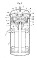
FIG. 1 is a cross-sectional view illustrating an overall construction of a scroll
compressor shown as a first embodiment of the present invention.
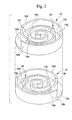
FIG. 2 is perspective views of a fixed scroll and an orbiting scroll used in the scroll
compressor.
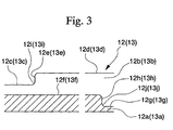
FIG. 3 is a cross-sectional view along a spiral direction of the fixed scroll and the
orbiting scroll.
FIG. 4A is a cross-sectional view along a lengthwise direction of a compression
chamber showing an engagement condition of the fixed scroll and the orbiting scroll at
room temperature.
FIG. 4B is a cross-sectional view along the lengthwise direction of the
compression chamber showing an engagement condition of the fixed scroll and the
orbiting scroll at the time of operation.
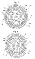
FIG. 5 is a diagram showing a process of fluid compression at the time of driving
the scroll compressor.
FIG. 6 is a diagram showing a process of fluid compression at the time of driving
the scroll compressor.
FIG. 7 is a diagram showing a process of fluid compression at the time of driving
the scroll compressor.
FIG. 8 is a diagram showing a process of fluid compression at the time of driving
the scroll compressor.
FIGS. 9A to 9D are diagrams showing developed shapes of the compression
chamber of the scroll compressor.
FIG. 10 is a cross-sectional view illustrating an overall construction of a scroll
compressor shown as a second embodiment of the present invention.
FIG. 11 is perspective views of a fixed scroll and an orbiting scroll used in the
scroll compressor.
FIG. 12 is a plan view of a fixed scroll used in the scroll compressor.
FIG. 13 is a diagram showing a process of fluid compression at the time of driving
the scroll compressor.
FIG. 14 is a diagram showing a process of fluid compression at the time of driving
the scroll compressor.
FIG. 15 is a diagram showing a process of fluid compression at the time of driving
the scroll compressor.
FIG. 16 is a diagram showing a process of fluid compression at the time of driving
the scroll compressor.
FIGS. 17A to 17D are diagrams showing developed shapes of the compression
chamber of the scroll compressor.
FIG. 18 is a cross-sectional view illustrating an overall construction of a scroll
compressor shown as a third embodiment of the present invention.
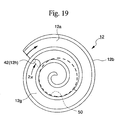
FIG. 19 is a plan view of a fixed scroll used in the scroll compressor.
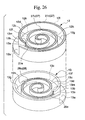
FIG. 20 is a perspective view showing a spiral reed valve being a discharge valve
used in the scroll compressor.
FIG. 21 is a plan view showing a positional relationship between the spiral reed
valve and a discharge port in a concavity of the fixed scroll of the scroll compressor.
FIG. 22 is a view of a circular reed valve being another form for the discharge
valve of the scroll compressor, seen from a cross-section through which the axis of the
discharge port of the fixed scroll passes.
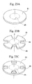
FIG. 23A is a perspective view of the same circular reed valve of the scroll
compressor.
FIG. 23B is a perspective view showing a modified example of the circular reed
valve of the scroll compressor.
FIG. 23C is a perspective view showing another modified example of the circular
reed valve of the scroll compressor.
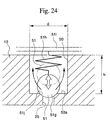
FIG. 24 is a view of a check valve being another form for the discharge valve of
the scroll compressor, seen from a cross-section through which the axis of the discharge
port of the fixed scroll passes.
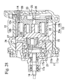
FIG. 25 is a cross-sectional view illustrating an overall construction of a scroll
compressor shown as a fourth embodiment of the present invention.
FIG. 26 is perspective views of a fixed scroll and an orbiting scroll used in the
scroll compressor.
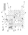
FIG. 27 is a side cross-sectional view showing a fixed scroll and plate, and a
pressing device.
FIG. 28 is a cross-sectional view illustrating an overall construction of a scroll
compressor shown as a fifth embodiment of the present invention.
FIG. 29 is perspective views of a fixed scroll and an orbiting scroll used in the
scroll compressor.
FIG. 30 is a plan view of a connecting rim and a connecting wall face seen from an
orbit axis direction.
FIGS. 31A and 31B are plan views of other forms for the connecting rim and the
connecting wall face seen from the orbit axis direction.
FIG. 32 is a cross-sectional view illustrating an overall construction of a scroll
compressor shown as a sixth embodiment of the present invention.
FIG. 33 is perspective views of a fixed scroll and an orbiting scroll used in the
scroll compressor.
FIG. 34 is a side cross-sectional view showing a lip provided between an upper rim
and a connecting rim, and a lip provided between a bottom face and a connecting wall face.
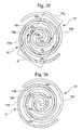
FIG. 35 is a view showing a process of fluid compression at the time of driving the
scroll compressor.
FIG. 36 is a view showing a process of fluid compression at the time of driving the
scroll compressor.
FIG. 37 is a view showing a process of fluid compression at the time of driving the
scroll compressor.
FIG. 38 is a view showing a process of fluid compression at the time of driving the
scroll compressor.
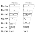
FIGS. 39A to 39G are diagrams showing a transition in shape of the compression
chamber from maximum volume up to minimum volume, in the scroll compressor.
FIG. 40 is a cross-sectional view illustrating an overall construction of a scroll
compressor shown as a seventh embodiment of the present invention.
FIG. 41A is a perspective view showing a fixed scroll used in a conventional scroll
compressor.
FIG. 41B is a perspective view showing an orbiting scroll used in a conventional
scroll compressor.
FIG. 42A is a plan view showing a state of engagement of the fixed scroll and the
orbiting scroll, for a compression chamber at the time of maximum volume, in the
conventional scroll compressor.
FIG. 42B is a cross-sectional view of the compression chamber formed at the outer
peripheral end side, for the compression chamber at the time of maximum volume, in the
conventional scroll compressor, seen from a cross-section along the spiral direction.
FIG. 43 is a cross-sectional view illustrating an engaged condition of the fixed
scroll and the orbiting scroll of the conventional scroll compressor seen from a cross-section
through which the axis of the discharge port passes.
BEST MODE FOR CARRYING OUT THE INVENTION
FIG. 1 shows the construction of a back pressure type scroll compressor
illustrating a first embodiment of the present invention.
The scroll compressor comprises; a sealed housing 11, a discharge cover 2 for
separating the housing 11 interior into a high pressure chamber HR and a low pressure
chamber LR, a frame 5, a suction pipe 6, a discharge pipe 7, a motor 8, a rotating shaft 16,
a rotation prevention mechanism 15, a fixed scroll 12, and an orbiting scroll 13 engaged
with the fixed scroll 12.
As shown in FIG. 2, the construction is such that for the fixed scroll 12, a spiral
wall 12b is upstanding on one side face of an end plate 12a. For the orbiting scroll 13, the
construction is such that a spiral wall 13b is upstanding on one side face of an end plate
13a as with the fixed scroll 12. In particular, the wall 13b is made substantially the same
shape as the wall 12b for the fixed scroll 12 side. The orbiting scroll 13 is assembled to
the fixed scroll 12, eccentric thereto by an orbit radius and out of phase by 180 degrees,
with the walls 12b and 13b engaged with each other.
In this back pressure type scroll compressor, the fixed scroll 12 is not completely
secured to the frame 5 with bolts or the like, and can move within a restricted range.
In this case, a cylindrical boss 18 is formed on the rear face side of the orbiting
scroll 13, and an eccentric portion 16b provided on an upper end of the rotation shaft 16
which is driven by the motor 8 for orbital movement, is inserted into the boss 18. As a
result, the orbiting scroll 13 performs orbital movement with respect to the fixed scroll 12,
while rotation thereof is prevented by the action of the rotation prevention mechanism 15.
On the other hand, the fixed scroll 12 is supported so as to float freely with respect
to the frame 5 secured to the housing 11 via a support spring 111, and a discharge port 25
for compressed fluid is provided in the center of the rear face of the end plate 3a.
Furthermore, around the discharge port 25 there is provided a cylindrical flange 116
protruding from the rear face of the end plate 12a of the fixed scroll 12, and this
cylindrical flange 116 is engaged with a cylindrical flange 117 on the discharge cover 2
side. At the portion where these cylindrical flanges 116 and 117 engage, the high pressure
chamber HR and the low pressure chamber LR are separated, and since it is necessary to
apply the high pressure (back pressure) to the rear face of the fixed scroll 12 to press this
downwards, a seal structure using a seal member 118 is adopted. This seal member 118
has a U-shape cross-section. The high pressure chamber HR in this case also functions as
a back pressure chamber which applies the high pressure discharge pressure to the rear
face of the fixed scroll 12.
On the end plate 12a of the fixed scroll 12, on the one side face on which the wall
12b is upstanding, there is provided a step 42 formed so that this is high on the central
portion side along the spiral direction of the wall 12b and low on the outer peripheral end
side.
For the end plate 13a for the orbiting scroll 13 side, as with the end plate 12a, on
the one side face on which the wall 13b is upstanding there is provided a step 43 formed
so as to be high on the central portion side along the spiral direction of the wall 13b and
low on the outer peripheral end side.
The steps 42 and 43 are provided at positions advanced by π (rad) from the outer
peripheral ends of the respective walls 12b and 13b, with the spiral center of the wall 12b
and the wall 13b as a reference.
By forming the step 42, the bottom face of the end plate 12a is divided into two
parts, namely a shallow bottom face 12f provided towards the central portion and a deep
bottom face 12g provided towards the outer peripheral end. The step 42 is formed
between the adjacent bottom faces 12f and 12g, so that a vertical sheer connecting wall
face 12h exists connecting the bottom faces 12f and 12g. By forming the step 43 on the
bottom face of the end plate 13a as with the end plate 12a, this is divided into two parts,
namely a shallow bottom face 13f provided towards the central portion and a deep bottom
face 13g provided towards the outer peripheral end. The step 43 is formed between the
adjacent bottom faces 13f and 13g, so that a vertical sheer connecting wall face 13h exists
connecting the bottom faces 13f and 13g.
Furthermore, for the wall 12b on the fixed scroll 12 side, corresponding to the step
43 of the orbiting scroll 13, the spiral shaped upper rim thereof is divided into two parts,
resulting in a stepped shape which is low at the central portion side of the spiral and high
at the outer peripheral end side. The wall 13b on the orbiting scroll 13 side also, as with
the wall 12b, corresponding to the stepped portion 42 of the fixed scroll 12, the spiral
shaped upper rim is divided into two parts, resulting in a stepped shape which is low at the
central portion side of the spiral and high at the outer peripheral end side.
More specifically, the upper rim of the wall 12b is divided into two parts, namely a
low upper rim 12c provided towards the central portion and a high upper rim 12d provided
towards the outer peripheral end, and between the adjacent upper rims 12c and 12d, there
exists a connecting rim 12e perpendicular to the orbit plane, which connects the two. The
wall 13b also as with the wall 12b is divided into two parts, namely a low upper rim 13c
provided towards the central portion and a high upper rim 13d provided towards the outer
peripheral end, and between the adjacent upper rims 13c and 13d, there exists a
connecting rim 13e perpendicular to the orbit plane, which connects the two.
The connecting rim 12e, when the wall 12b is viewed in the direction from the
orbiting scroll 13, is smoothly continuous with the inner and outer two side faces of the
wall 12b, and forms a semicircle having a diameter equal to the thickness of the wall 12b.
The connecting rim 13e also, as with the connecting rim 12e, is smoothly continuous with
the inner and outer two side faces of the wall 13b, and forms a semicircle having a
diameter equal to the thickness of the wall 13b.
Furthermore, the connecting wall face 12h, when the end plate 12a is viewed from
the orbit axis direction, forms a circular arc coinciding with an envelope drawn by the
connecting rim 13e along the orbit of the orbiting scroll, and the connecting wall face 13h
also, as with the connecting wall face 12h, forms a circular arc coinciding with an
envelope drawn by the connecting rim 12e.
Here a tip seal is not provided on the upper rim of the wall 12b of the fixed scroll
12 and the wall 13b of the orbiting scroll 13, and sealing of a later described compression
chamber C is performed by pressing the edge face of the walls 12b and 13b against the
end plates 12a and 13a.
As shown in FIG. 3, on the wall 12b, at the portion where the upper rim 12c and
the connecting rim 12e approach each other, a rib 12i is provided to give build up. The rib
12i is for avoiding stress concentration, and constitutes a concave surface formed integral
with the wall 12b and smoothly continuous with the upper rim 12c and the connecting rim
12e. On the wall 13b also, at the portion where the upper rim 13c and the connecting rim
13e approach each other, a rib 13i is provided in the same shape for a similar reason.
On the end plate 12a also, at the portion where the bottom face 12g and the
connecting wall face 12h approach each other, a rib 12j is provided to give build up. The
rib 12j is for avoiding stress concentration, and constitutes a concave surface formed
integral with the wall 12b and smoothly continuous with the bottom face 12g and the
connecting wall face 12h. On the end plate 13a also, at the portion where the bottom face
13g and the connecting wall face 13h approach each other, a rib 13j is provided in the
same shape for a similar reason.
On the wall 12b, the portion where the upper rim 12d and the connecting rim 12e
approach each other, and on the wall 13b, the portion where the upper rim 13d and the
connecting rim 13e approach each other, are respectively chamfered in order to avoid
interference with the ribs 13j and 12j at the time of assembly.
When the orbiting scroll 13 is assembled to the fixed scroll 12, the low upper rim
13c abuts against the shallow bottom face 12f, and the high upper rim 13d abuts against
the deep bottom face 12g. At the same time, the low upper rim 12c abuts against the
shallow bottom face 13f, and the high upper rim 12d abuts against the deep bottom face
13g. As a result, between the two scrolls is compartmentalized by the facing end plates
12a and 13a and the walls 12b and 13b to form a compression chamber C.
With the orbiting scroll 13 assembled to the fixed scroll 12, the cross-section along
the lengthwise direction of the compression chamber C is shown in FIG. 4A. FIG. 4A
shows the engagement condition of the end plate 12a of the fixed scroll 12 and the wall
13b of the orbiting scroll 13, for when the orbiting scroll 13 is assembled to the fixed
scroll 12, in a room temperature condition.
As shown in the figure, a clearance 121 of a height δ2 is formed between the
bottom face 12f and the upper rim 13c, and a clearance 122 of a height δ1 is formed
between the bottom face 12g and the upper rim 13d. The height of these clearances 121
and 122 is set so that δ2 > δ1 results.
In FIG. 4B, the scroll compressor of the present example has been operated so that
the fixed scroll 12 and the orbiting scroll 13 are in a thermally expanded condition. As
shown in the figure, the height of the clearance 121 between the bottom face 12f and the
upper rim 13c becomes δ2', and the height of the clearance 122 between the bottom face
12g and the connecting rim 13e becomes δ1'. The values for these δ1' and δ2' are
approximately 10 µm to 50 µm.
Furthermore, while omitted from the figure, the engagement of the end plate 13a of
the orbiting scroll 13 and the wall 12b of the fixed scroll 12 is constructed similarly to the
above construction. That is, a clearance of a height δ2 is formed between the bottom face
13f and the upper rim 12c, and a clearance of a height δ1 (< δ2) is formed between the
bottom face 13g and the upper rim 12d.
The compression chamber C moves towards the central portion from the outer
peripheral end following the orbital movement of the orbiting scroll 13. However, while
the contact point of the walls 12b and 13b exists towards the outer peripheral end from the
connecting rim 12e, the connecting rim 12e slides on the connecting wall face 13h so that
leakage of fluid between the adjacent compression chambers C (one not in the sealed
condition) on either side of the wall 12 does not occur, and while the contact point of the
walls 12b and 13b does not exist towards the outer peripheral end from the connecting rim
12e, this does not slide on the connecting wall face 13h, in order to ensure an equal
pressure between the compression chambers C (both in the sealed condition) on either side
of the wall 12.
The connecting rim 13e also in a similar manner, while the contact point of the
walls 12b and 13b exists towards the outer peripheral end from the connecting rim 12e,
slides on the connecting wall face 12h so that leakage of fluid between the adjacent
compression chambers C (one not in the sealed condition) on either side of the wall 13
does not occur, and while the contact point of the walls 12b and 13b does not exist
towards the outer peripheral end from the connecting rim 13e, this does not slide on the
connecting wall face 12h, in order to ensure an equal pressure between the compression
chambers C (both in the sealed condition) on either side of the wall 13. Here the sliding
contact of the connecting rim 12e and the connecting wall face 13h, and the connecting
rim 13e and the connecting wall face 12h occurs in the same period during a half rotation
of the orbiting scroll 13.
The process of fluid compression at the time of driving the scroll compressor
constructed as described above is explained sequentially as shown in FIG. 5 through FIG.
8.
In the condition shown in FIG. 5, two compression chambers C of maximum
volume are formed at opposite positions on either side of the center of the scroll
compression mechanism, by abutting the outer peripheral end of the wall 12b against the
outside face of the wall 13b, and abutting the outer peripheral end of the wall 13b against
the outside face of the wall 12b, and a fluid is introduced to between the end plates 12a
and 13a, and the walls 12b and 13b. At this point in time, the connecting rim 12e and the
connecting wall face 13h, and the connecting rim 13e and the connecting wall face 12h are
slidingly contacted. Subsequently, immediately after, they contacted are separated from
each other.
In the process where the orbiting scroll 13 orbits by π/2 from the condition of FIG.
5 to reach the condition shown in FIG. 6, the compression chambers C proceed towards
the central portion while maintaining the sealed condition, so that the volume is gradually
reduced and the fluid compressed, and compression chambers C0 which precede the
compression chambers C also proceed towards the central portion while maintaining the
sealed condition, so that the volume is gradually reduced to continuously compress the
fluid. In this process, the respective sliding contacts between the connecting rim 12e and
the connecting wall face 13h, and the connecting rim 13e and the connecting wall face 12h
are cancelled, and the two adjacent compression chambers C on either side of the wall 13b
become a communicated condition with equal pressure.
In the process where the orbiting scroll 13 orbits by π/2 from the condition of FIG.
6 to reach the condition shown in FIG. 7, the compression chambers C proceed towards
the central portion while maintaining the sealed condition, and the volume is gradually
reduced and the fluid compressed, and the compression chambers C0 also proceed towards
the central portion while maintaining the sealed condition and the volume is gradually
reduced and the fluid is continuously compressed. In this process, the equal pressure
between the two adjacent compression chambers C continues, with the respective sliding
contacts between the connecting rim 12e and the connecting wall face 13h, and the
connecting rim 13e and the connecting wall face 12h being cancelled.
In the condition shown in FIG. 7, between the inside face of the wall 12b close to
the outer peripheral end and the outside face of the wall 13b positioned inwards thereof,
there is formed a space C1 which subsequently becomes a compression chamber.
Similarly between the inside face of the wall 13b close to the outer peripheral end and the
outside face of the wall 12b positioned inwards thereof, there is also formed a space C1
which subsequently becomes a compression chamber. A low pressure fluid flows from
the low pressure chamber LR to these spaces C1. At this point in time, the connecting rim
12e and the connecting rim 13e start respective sliding contact with the connecting wall
face 13h and the connecting wall face 12h, so that a sealed condition of the compression
chambers C preceding the space C1 is maintained.
In the process where the orbiting scroll 13 rotates by π/2 from the condition of FIG.
7 to reach the condition shown in FIG. 8, the spaces C1 proceed towards the central
portion of the scroll compression mechanism, while the size expands, and the compression
chambers C preceding the spaces C1 also proceed towards the central portion so that the
volume is gradually reduced to compress the fluid. In this process, the respective sliding
contact between the connecting rim 12e and the connecting wall face 13h, and the
connecting rim 13e and the connecting wall face 12h continues, so that the sealed
condition of the compression chambers C is maintained with a seal between the spaces C1.
In the process where the orbiting scroll 13 orbits further by π/2 from the condition
of FIG. 8 to again reach the condition shown in FIG. 5, the spaces C1 proceed towards the
central portion of the scroll compressor mechanism while the size is further increased, and
the compression chambers C preceding the spaces C1 also proceed towards the central
portion while maintaining the sealed condition, so that the volume is gradually reduced to
compress the fluid. In this process however, the respective sliding contact between the
connecting rim 12e and the connecting wall face 13h, and the connecting rim 13e and the
connecting wall face 12h is cancelled, but the sealed condition of the compression
chambers C is maintained with a seal between the spaces C1. Then, when the condition of
FIG. 5 is reached, the compression chambers C shown in FIG. 8 correspond to the
compression chambers C0 shown in FIG. 5 and the spaces C1 shown in FIG. 8 correspond
to the compression chambers C shown in FIG. 5.
After this, by continuing the compression, the compression chambers C become a
minimum volume and the fluid is discharged from the compression chambers C.
The discharged fluid is introduced to the high pressure chamber HR. Then, the
fixed scroll 12 is subjected to the high pressure back pressure and is pressed against the
orbiting scroll 13 side. Furthermore, in the seal member 118, by introducing the high
pressure fluid to inside the U-shape portion, this is expanded by the differential pressure
so that the seal face is pressed towards the vertical faces of the circular flanges 116 and
117 to thereby seal between the high pressure chamber HR and the low pressure chamber
LR.
Next is a description of the shape change of the compression chambers C.
The change of the size of the compression chambers C from the maximum volume
to the minimum volume is shown by; the compression chambers C in FIG. 5 → the
compression chambers C in FIG. 7 → the compression chambers C0 in FIG. 5 → the
compression chambers C0 in FIG. 8. Here the developed shapes of the compression
chamber in the respective conditions are shown in FIG. 9A to FIG. 9D.
In the condition of maximum volume of FIG. 9A, the compression chamber
becomes a variable strip shape with the width becoming narrower along the orbit axis
direction. This width, at the outer peripheral end side of the scroll compressor becomes a
lap length Ll approximately equal to the height of the wall 12b from the bottom face 12g
to the upper rim 12d (or the height of the wall 13b from the bottom face 13g to the upper
rim 13d), and at the central portion side, this becomes a lap length Ls (< Ll)
approximately equal to the height from the bottom face 12f to the upper rim 12d (or the
height of the wall 13b from the bottom face 13f to the upper rim 13d).
Also in the condition of FIG. 9B, the compression chamber becomes a variable
strip shape with the width becoming narrower along the orbit axis direction. This width,
at the outer peripheral end side of the scroll compressor becomes a lap length Ls, and at
the central portion side, this becomes a lap length Lss (< Ls) approximately equal to the
height from the bottom face 12f to the upper rim 12c (or the height of the wall 13b from
the bottom face 13f to the upper rim 13c).
Furthermore, with progress of compression, as shown in FIG. 9C, the width of
compression chamber becomes a uniform lap length Lss.
Then as shown in FIG. 9D, the length thereof becomes a minimum so that the
compression chamber becomes a minimum volume.
As described above, in the scroll compressor of this example, in the room
temperature condition the clearance 121 of a height δ2 is formed between the bottom face
12f and the upper rim 13c, and the clearance 122 of height δ1 is formed between the
bottom face 12g and the upper rim 13d. Furthermore, the height of these clearances 121
and 122 is set so that δ2 > δ1 results. Then, when the scroll compressor of this example is
operated, this becomes a higher temperature closer to the central portion of the scroll, and
the amount of thermal expansion of the walls 12b and 13b increases. Here, since δ2 > δ1
results as mentioned above, the difference in the expansion amount between the central
portion and the outer peripheral portion is compensated for. Hence after expansion, the
heights δ1' and δ2' of the clearances 121 and 122 both become suitable values, so that
compression at good efficiency can be performed.
Furthermore, the height of the clearances 121 and 122 is setup beforehand so that
even if the walls 12b and 13b are thermally expanded, these do not come in contact with
the respective end plates 13a and 12a. Therefore, when the scroll compressor is operated,
the walls 12b and 13b and the end plates 13a and 12a do not come in contact and hinder
the orbital movement of the orbiting scroll 13.
Furthermore, in the abovementioned scroll compressor, the volume change of the
compression chamber is not brought about by only a reduction in the cross-section area
parallel to the orbit plane as heretofore, but as shown in FIG. 9A to FIG. 9D, is brought
about by a combination of a reduction in the width in the orbit axis direction and a
reduction in the cross-section area.
Consequently, by making the walls 12b and 13b a stepped shape, changing the lap
length of the walls 12b and 13b near the outer peripheral end and near the central portion
of the scroll compressor, and increasing the maximum volume and reducing the minimum
volume of the compression chambers C, then compared to the conventional scroll
compressor where the lap length of the wall pairs are constant, the compression ratio can
be improved.
Furthermore, by introducing the back pressure to the high pressure chamber HR,
the fixed scroll 12 is pressed towards the orbiting scroll 13. Therefore, sealing of the
compression chamber C can be performed without using a tip seal.
In the above, for the walls 12b and 13b, since the amount of expansion at the
central portion side is large, the height of the clearances 121 and 122 is set so that δ2 > δ1
results.
In general, if the walls 12b and 13b are high, the displacement in the height
direction due to expansion is large. That is, since the height dimension of the walls 12b
and 13b of the central portion side is made small compared to that of the walls 12b and
13b of the outer peripheral end side, then for the same temperature, the displacement of
the central side due to thermal expansion is smaller. Consequently, the height of the
clearances 121 and 122 for the central portion side and the outer peripheral end side of the
step can be determined taking these conditions into consideration. That is, since the walls
12b and 13b are a stepped shape, the height of the walls can be made different at the
central portion side of the step to the outer peripheral end portion side. Therefore
depending on the heights of the respective walls 12b and 13b on the central portion side
and the outer peripheral end side, the height of the respective clearances 121 and 122 may
be formed the same, or the height of the clearance 121 for the central portion side may be
less than for the clearance 122.
In addition, in the abovementioned embodiment, the connecting rims 12e and 13e
are formed perpendicular to the orbit plane of the orbiting scroll 13, and the connecting
wall faces 12h and 13h corresponding to these are also formed perpendicular to the orbit
plane. However, if the connecting rims 12e and 13e, and the connecting wall faces 12h
and 13h maintain a corresponding relationship with each other, then it is not necessary for
these to be perpendicular to the orbit plane, and for example, these may be formed at an
incline to the orbit plane.
Furthermore, it is not necessary that the connecting rims 12e and 13e form a
semicircle, and these may be any shape. In this case, the envelope drawn by the
connecting rims 12e and 13e does not become a circular arc, and hence the connecting
wall faces 12h and 13h are also no longer a circular arc.
Moreover, the places where the steps 42 and 43 are formed need not each be at the
same place, and these may be respectively provided at a plurality of places.
A second embodiment of a scroll compressor according to the present invention
will now be described referring to FIG. 10 through FIG. 17A to FIG. 17D. Description is
omitted for points similar to those in the first embodiment.
FIG. 10 is a cross-sectional view showing an overall construction of a scroll
compressor according to the present invention.
In this scroll compressor, a housing 11 comprises a cup-like housing body 11a, and
a cover plate 11b secured to an opening end of the housing body 11a.
The scroll compressor comprising a fixed scroll 12 and an orbiting scroll 13 is
disposed inside the housing 11. The fixed scroll 12 is formed with a spiral wall 12b
upstanding on one side face of an end plate 12a. The orbiting scroll 13, as with the fixed
scroll 12 is formed with a spiral wall 13b upstanding on one side face of an end plate 13a.
In particular, the wall 13b is made substantially the same shape as the wall 12b for the
fixed scroll 12 side. Furthermore, on upper rims of the walls 12b and 13b, there is
disposed tip seals 27 and 28 for increasing gas tightness of the compression chambers C as
described later (a description is given later for these tip seals 27 and 28).
The fixed scroll 12 is fastened to the housing body 11a with bolts 14. Moreover
the orbiting scroll 13 is assembled to the fixed scroll 12, eccentric thereto by a mutual
orbit radius and out of phase by 180 degrees, with the walls 12b and 13b engaged with
each other, and is supported so as to be orbitally movable with rotation prevented by
means of a rotation prevention mechanism 15 provided between the cover plate 11b and
the end plate 13a.
A rotating shaft 16 incorporating a crank 16a is passed through the cover plate 11b,
and is rotatably supported on the cover plat 11b via bearings 17a and 17b.
A boss 18 is protrudingly provided on the central portion of the other end face of
the end plate 13a on the orbiting scroll 13 side. An eccentric portion 16b of the crank 16a
is rotatably accommodated in the boss 18 via a bearing 19 and a drive bush 20, so that the
orbiting scroll 13 is orbitally moved by rotating the rotating shaft 16. Furthermore, a
balance weight 21 for counteracting an imbalance amount exerted on the orbiting scroll 13,
is fitted to the rotating shaft 16.
A suction chamber 22 is formed in an interior of the housing 11 around the fixed
scroll 12. Furthermore, a discharge cavity 23 is formed by compartmentalizing a bottom
face inside the housing body 11a and the other side face of the end plate 12a.
A suction port 24 for guiding low pressure fluid towards the suction chamber 22, is
provided in the housing body 11a, and discharge port 25 for guiding high pressure fluid
towards the discharge cavity 23 from the compression chambers C which move to the
central portion while the volume is gradually reduced, is provided at the center of the end
plate 12a on the fixed scroll 12 side. Moreover, a discharge valve 26 which opens the
discharge port 25 only when a pressure greater than a predetermined amount acts, is
provided on the other side face center of the end plate 12a.
FIG. 11 is respective perspective views of the fixed scroll 12 and the orbiting scroll
13.
Steps 42 and 43 are provided at positions 2π (rad) from the outer peripheral ends
of the respective walls 12b and 13b, with the spiral centers of the wall 12b and the wall
13b as a reference.
As shown in FIG. 12, the spiral shape wall 12b forms a spiral shape flow path 45
between wall portions, and the circular arc center of the connecting wall face 12h
constituting the step 42 is positioned in the widthwise center of the flow path 45 at a
position where the flow path 45 has advanced 2π (rad) from the outer peripheral end of the
wall 12b to the central side, with the spiral center of the wall 12b as a reference. Here the
circular arc center of the connecting wall face 12h is positioned on an outer peripheral end
side from a position where the flow path 45 has advanced 2π (rad) from a discharge port
25 forming position to the outer peripheral end side along the wall 12b.
The circular arc center of the connecting wall face 13h also is similarly a point
advanced 2π (rad) from the outer peripheral end of the wall 12b to the center side, and is
positioned at the widthwise center of the flow path 46 formed between the wall portions of
the wall 13b, and is positioned on an outer peripheral end side from a position advanced
2π (rad) from the discharge port 25 forming position to the outer peripheral end side.
Furthermore, as shown in FIG. 11, tip seals 27c, 27d and 27e are respectively
disposed in the upper rims 12c and 12d and the connecting rim 12e of the wall 12b. In a
similar manner, tip seals 28c, 28d, and 28e are also respectively disposed in the upper rims
13c and 13d and the connecting rim 13e of the wall 13.
The process of fluid compression at the time of driving the scroll compressor
constructed as described above is explained sequentially as shown in FIG. 13 through FIG.
16.
In the condition shown in FIG. 13, two compression chambers C of maximum
volume are formed at opposite positions on either side of the center of the scroll
compression mechanism, by abutting the outer peripheral end of the wall 12b against the
outside face of the wall 13b, and abutting the outer peripheral end of the wall 13b against
the outside face of the wall 12b, and a fluid is introduced to between the end plates 12a
and 13a, and the walls 12b and 13b. At this point in time, the connecting rim 12e and the
connecting wall face 13h, and the connecting rim 13e and the connecting wall face 12h are
slidingly contacted.
In the process where the orbiting scroll 13 orbits by π/2 from the condition of FIG.
13 to reach the condition shown in FIG. 14, the compression chambers C proceed towards
the central portion while maintaining the sealed condition, so that the volume is gradually
reduced and the fluid compressed, and compression chambers C0 which precede the
compression chambers C also proceed towards the central portion while maintaining the
sealed condition, so that the volume is gradually reduced to continuously compress the
fluid. In this process, the connecting rim 12e starts sliding contact with the connecting
wall face 13h, and the connecting rim 13e starts sliding contact with the connecting wall
face 12h, and the sealed condition of the compression chambers C0 which precede the
compression chambers C is maintained.
In the process where the orbiting scroll 13 orbits by π/2 from the condition of FIG.
14 to reach the condition shown in FIG. 15, the compression chambers C proceed towards
the central portion while maintaining the sealed condition, and the volume is gradually
reduced and the fluid compressed, and the compression chambers C0 which precede the
compression chambers C also proceed towards the central portion while maintaining the
sealed condition and the volume is gradually reduced and the fluid is continuously
compressed. At this point in time, the connecting rim 12e and the connecting wall face
13h, and the connecting rim 13e and the connecting wall face 12h are slidingly contacted.
However immediately after, this is cancelled.
In the condition shown in FIG. 15, between the inside face of the wall 12b close to
the outer peripheral end and the outside face of the wall 13b positioned inwards thereof,
there is formed a space C1 which subsequently becomes a compression chamber.
Similarly between the inside face of the wall 13b close to the outer peripheral end and the
outside face of the wall 12b positioned inwards thereof, there is also formed a space C1
which subsequently becomes a compression chamber. A low pressure fluid flows from
the suction chamber 22 to these spaces C1.
In the process where the orbiting scroll 13 orbits by π/2 from the condition of FIG.
15 to reach the condition shown in FIG. 16, the spaces C1 proceed towards the central
portion of the scroll compression mechanism, while their size expands, and the
compression chambers C preceding the spaces C1 also proceed towards the central portion
so that the volume is gradually reduced to compress the fluid. In this process, the
respective sliding contact between the connecting rim 12e and the connecting wall face
13h, and the connecting rim 13e and the connecting wall face 12h is cancelled so that the
adjacent two compression chambers C become equal pressure.
In the process where the orbiting scroll 13 orbits further by π/2 from the condition
of FIG. 16 to again reach the condition shown in FIG. 13, the spaces Cl proceed towards
the central portion of the scroll compressor mechanism while the size is further increased,
and the compression chambers C preceding the spaces C1 also proceed towards the central
portion while maintaining the sealed condition, so that the volume is gradually reduced to
compress the fluid. Then, when the condition of FIG. 13 is reached, the compression
chambers C shown in FIG. 16 correspond to the compression chambers C0 shown in FIG.
13 and the spaces C1 shown in FIG. 16 correspond to the compression chambers C shown
in FIG. 13.
After this, by continuing the compression, the compression chambers C become a
minimum volume and discharges the fluid from the scroll compressor.
The change of the size of the compression chambers C from the maximum volume
to the minimum volume (the volume when the discharge valve 26 is open) is shown by;
the compression chambers C in FIG. 13 → the compression chambers C in FIG. 15 → the
compression chambers C0 in FIG. 13 → the compression chambers C0 in FIG. 16. Here
the developed shapes of the compression chamber in the respective conditions are shown
in FIG. 17A to FIG. 17D.
In the condition of maximum volume of FIG. 17A, the width of the compression
chamber becomes a lap length Ll approximately equal to the height of the wall 12b from
the bottom face 12g to the upper rim 12d (or the height of the wall 13b from the bottom
face 13g to the upper rim 13d).
In the condition of FIG. 17B, the compression chamber becomes a variable section
thin strip shape with the width becoming narrower along the orbit axis direction. This
width, at the outer peripheral end side of the scroll compressor becomes a lap length Ll,
and at the central portion side, this becomes a lap length Ls (< Ll) approximately equal to
the height from the bottom face 12f to the upper rim 12d (or the height of the wall 13b
from the bottom face 13f to the upper rim 13d).
Also in the condition of FIG. 17C, the compression chamber becomes a variable
section thin strip shape with the width becoming narrower along the orbit axis direction.
This width, at the outer peripheral end side of the scroll compressor becomes a lap length
Ls, and at the central portion side, this becomes a lap length Lss (< Ls) approximately
equal to the height from the bottom face 12f to the upper rim 12c (or the height of the wall
13b from the bottom face 13f to the upper rim 13c).
In the condition of minimum volume of FIG. 17, the compression chamber
becomes a thin strip shape with the width uniform (lap length Lss).
In the abovementioned scroll compressor, the volume change of the compression
chamber is not brought about by only a reduction in the cross-section area parallel to the
orbit plane as heretofore, but as shown in FIG. 17A to FIG. 17D, is brought about by a
combination of a reduction in the width in the orbit axis direction and a reduction in the
cross-sectional area.
Consequently, by making the walls 12b and 13b a stepped shape, changing the lap
length of the walls 12b and 13b near the outer peripheral end and near the central portion
of the scroll compressor, and increasing the maximum volume and reducing the minimum
volume of the compression chambers C, then compared to the conventional scroll
compressor where the lap length of the wall pairs are constant, the compression ratio can
be improved.
Moreover, since the steps 42 and 43 are respectively positioned 2π (rad) from the
spiral outer peripheral end of the walls 12b and 13b, then when the compression chamber
is a maximum volume as shown in FIG. (20A), the lap length thereof can be a maximum
along the whole area in the spiral direction.
Furthermore, when the steps 42 and 43 come too close to the center of the spiral,
the differential pressure of the compression chamber which the walls 12b and 13b
partition on the inside and outside becomes large, and hence the fluid inside the
compression chamber on the inside is likely to pass through the steps 42 and 43 and leak
to the compression chamber on the outside. However, in this example, since the steps 42
and 43 as described above are positioned 2π (rad) from the spiral outer peripheral end of
the walls 12b and 13b, the maximum volume of the compression chamber can be made a
maximum, and at the same time the leakage of the fluid due to the differential pressure can
be suppressed. Furthermore, since the wall portions 42 and 43 are provided at a position
advanced more than 2π (rad) from the discharge port 25 to the outer peripheral end side,
the compression chambers C containing the steps 42 and 43 do not face the discharge port
25. Consequently, the compression chambers containing the steps 42 and 43 do not
become discharge pressure, and hence the seal pressure differential between the spiral
central portion side and the outer peripheral end side on either side of the steps can be kept
small, enabling leakage of refrigerant to be suppressed.
If the step 42 and 43 are not 2π (rad) from the spiral outer peripheral end of the
walls 12b and 13b, but are within a range in the vicinity of 2π (rad), for example, 2π ± π/4
(rad), then since this only differs by a few percent from the volume ratio for 2π (rad), the
maximum volume of the compression chamber can be kept sufficiently large, and leakage
of fluid inside the compression chamber caused by the abovementioned pressure
differential can also be prevented.
Moreover, if the steps 42 and 43 are at a position which at least exceeds π from the
outer peripheral end of the walls 12b and 13b, the maximum volume of the compression
chamber can be made greater than heretofore, and compression efficiency can be
improved.
The places where the steps 42 and 43 are formed need not each be at the same
place, and these may be respectively provided at a plurality of places.
In addition, in the abovementioned embodiment, the connecting rims 12e and 13e
are formed perpendicular to the orbit plane of the orbiting scroll 13, and the connecting
wall faces 12h and 13h corresponding to these are also formed perpendicular to the orbit
plane. However, if the connecting rims 12e and 13e, and the connecting wall faces 12h
and 13h maintain a corresponding relationship with each other, then it is not necessary for
these to be perpendicular to the orbit plane, and for example, these may be formed at an
incline to the orbit plane.
Furthermore, it is not necessary that the connecting rims 12e and 13e form a
semicircle, and these may be any shape. In this case, the envelope drawn by the
connecting rims 12e and 13e does not become a circular arc, and hence the connecting
wall faces 12h and 13h are also no longer a circular arc.
In the above description, the steps 42 and 43 are provided position advanced more
than 2π (rad) from the discharge port 25 to the outer peripheral end side. However, in the
case of a scroll where the number of turns is small, as long as the steps 42 and 43 are
provided at a position exceeding at least a pitch angle π (rad) from the outer peripheral end
towards the central portion along the spiral of the scroll wall, these may be provided at a
position less than 2π (rad) from the discharge port towards the outer peripheral end side.
A third embodiment of a scroll compressor according to the present invention will
now be described while referring to FIG. 18 to FIG. 22. Description is omitted for points
similar to those in the first and second embodiment.
FIG. 18 is a cross-sectional view showing an overall construction of a scroll
compressor of this embodiment. Furthermore, FIG. 19 is a perspective view of the fixed
scroll as used in this scroll compressor, viewed from the side on which the wall is
provided. Moreover, FIG. 20 is a perspective view showing a spiral reed valve being a
discharge valve used in this scroll compressor. Furthermore, FIG. 21 is a plan view
showing a positional relationship between the spiral reed valve and an opening of a
discharge port, in a concavity on a rear face of the fixed scroll of the scroll compressor.
The scroll compressor of this embodiment is one where the concavity formed on
the rear face of the fixed scroll and the discharge valve provided in the concavity have a
special characteristic. At first, however a description is given of the overall construction
of the scroll compressor, and after this the description will continue for details of the
concavity and the discharge valve.
In FIG. 18, in a concavity 50 formed in the other side face center (rear face center)
of the end plate 12a there is provided a discharge valve 51 which opens a discharge port
25 only when a pressure greater than a predetermined amount acts (details of the
concavity 50 and the discharge valve 51 are given later).
Steps 42 and 43 are formed between positions up to 2π ± π/4 (rad) from the outer
peripheral ends of the respective walls 12b and 13b, with the spiral centers of the wall 12b
and the wall 13b as a reference.
Furthermore, a description of the concavity 50 and the discharge valve 51 which
are the features of this embodiment is given hereunder.
As shown in FIG. 19, in the case where the side of the end plate 12a of the fixed
scroll 12 which is formed with the wall 12b is the front face (the face towards the
compression chamber C side) and the opposite side is the rear face (the face towards the
discharge cavity 23 side), then viewing facing from the rear face side, the concavity 50 is
formed so as to be positioned more to the central side than the deep bottom face 12g (low
position) formed on the front face side.
To explain in more detail, since the step 42 (stepped portion) is formed at a
position up to 2π ± π/4 (rad) at a pitch angle from the outer peripheral end towards the
central portion along the spiral of the wall 12b thereof, then in the case where the end
plate 12a is viewed facing from the rear face side, the concavity 50 is constructed
positioned on the inside with the periphery surrounded by the annular shape bottom face
12g which goes around once from the outer peripheral end up to the step 42.
Furthermore, the shape of the concavity 50 as shown in FIG. 19 constitutes a circle
on a line of sight perpendicular to the end plate 12a. Moreover, in the thickness direction,
as shown in FIG. 18, this is formed so as to be sunken with a constant depth h below the
rear face of the end plate 12b, thus giving a concave space of an approximate disc shape.
By deepening the depth h of the concavity 50, the thickness t of the portion
surrounding the discharge port 25 of the wall 12b is thinned. Consequently, the volume V
inside the discharge port 25 can be made small without narrowing the flow path area.
However, in the design of the depth h of this concavity 50, taking into consideration the
fluid pressure applied to the end plate 12b, and then of course the design must be such that
a thickness t which retains sufficient strength can be maintained.
Furthermore, a description will now be give of the discharge valve 51 housed
inside the concavity 50. As shown in FIG. 20 and FIG. 21, the discharge valve 51 of this
embodiment is a spiral reed valve having a blocking portion 51a for covering and closing
the opening of the discharge port 25, a resilient portion 51b formed in a spiral shape from
the blocking portion 51a, and a securing portion 51c and bolt 51d for securing the outer
peripheral end of the resilient portion 51b to a bottom face 50a of the concavity 50.
The blocking portion 51a has a comparatively large surface area compared to the
opening area of the discharge port 25, so that when in contact with the bottom face 50a,
this can sufficiently cover and close the opening of the discharge port 25.
The resilient portion 51b is a spiral shape plate spring connected to the blocking
portion 51a and formed so as to spiral around the periphery thereof. In the case where a
fluid pressure is applied to the blocking portion 51a in the plate thickness direction, this
can urge the blocking portion 51a which is separated from the bottom face 50a, so as to
again contact with the bottom face 50a.
The securing portion 51c is a portion at the end of the spiral of the resilient portion
51b, and is formed with a through hole for taking the bolt 51d. Similarly, the bottom face
50a of the concavity 50 is formed with an internal thread 50b for threading with the bolt
50d. In a condition with the securing portion 51c secured to the bottom face 50a by the
bolt 51d, the blocking portion 51a is attached in a condition covering the opening of the
discharge port 25 and closely contacted with the bottom face 50a.
The respective plate thicknesses for the blocking portion 51 a, the resilient portion
51b, and the securing portion 51c may all be the same, or other designs may be adopted
where for example only the resilient portion 51b is made thinner or thicker than the others
to adjust the spring strength, or where the plate thickness is different for each part.
Furthermore, in order to prevent excessive deformation of the resilient portion 51b,
a construction may be adopted as required, with a stopper (not shown in the figure)
provided above the blocking portion 51a for obstructing raising of the blocking portion
51a above a certain height.
According to the scroll compressor of this embodiment having the above described
construction, when the rotating shaft 16 is rotated about the axis thereof by a motor (not
shown in the figure), the eccentric portion 16b moves the orbiting scroll 13 orbitally while
rotation with respect to the fixed scroll 12 is prevented. As a result, low pressure fluid
drawn in from the suction port 24 is gradually reduced in volume inside the respective
compression chambers C and moves slowly under high pressure, from the outer peripheral
end side towards the central portion side, and finally passes through the discharge port 25
and is discharged to the discharge cavity 23.
The fluid at this time pushes the blocking portion 51a of the discharge valve 51
(spiral reed valve) against the urging force of the resilient portion 51b and the pressure
inside the discharge cavity 23, so that an opening is produced in the discharge port 25, and
the fluid flows out via this to inside the discharge cavity 23. As a result, the interior of the
discharge cavity 23 is raised in pressure by the inflow of high pressure fluid, and the
blocking portion 51a is again forced so as to tightly close against the bottom face 50a.
With the closing of the opening of the discharge port 25 in this way, a little fluid
remains inside the discharge port 25. However, since the volume V inside the discharge
port 25 is minimized due to the shape of the concavity 50a, practically all of the fluid is
smoothly discharged to the discharge cavity 23. Hence compared to the conventional
scroll compressor, the pressure of the fluid to be compressed next less likely to be raised.
Furthermore, by forming the concavity 50, the thickness t of the part of the end
plate 12a of the fixed scroll 12 where the discharge port 25 is positioned can be made thin.
Consequently, the volume V inside the discharge port 25 can be narrowed. Therefore, the
volume of fluid remaining here can be reduced. Consequently, fluid which reverse flows
from inside the discharge port 25 towards the compression chamber C can be reduced as
much as possible, and hence the pressure of the fluid which is to be compressed next is no
longer raised, and the power for rotating the orbiting scroll 13 is minimized. Hence there
is no impairment due to fluid remaining inside the discharge port 25, thus enabling
operating efficiency to be improved.
Furthermore, since the concavity 50 is constructed positioned on the inside of the
annular shape bottom face 12g which goes around once from the outer peripheral end
along the spiral of the wall 12b up to the step 42 at a pitch angle of 2π ± π/4 (rad) towards
the center portion, this gives a comparatively narrow space. However, since a spiral reed
valve being a comparatively small valve is adopted as the discharge valve 51, this can be
easily installed even in this narrow concavity 50.
However, if the discharge valve 6 of the rectangular shape plate form in the
conventional technology is to be provided in this narrow concavity 50, since this discharge
valve 6 must have a certain length in order to ensure resilience, this cannot be
accommodated inside the concavity 50.
On the other hand, in the present embodiment, since a spiral reed valve having a
compact resilient portion 51b of a spiral shape is adopted, this can be accommodated
without difficulty inside the concavity 50 with the resilience ensured.
Furthermore, in this embodiment, since the construction is such that the resilient
portion 51b presses the blocking portion 51a against the opening of the discharge port 25,
this is not subjected to the action of gravity. Hence, even if the scroll compressor itself is
positioned vertically or horizontally, the function of the discharge valve 51 is not lost, thus
giving a scroll compressor for which the installation degree of freedom is high.
Next is a description of a fourth embodiment of a scroll compressor of the present
invention with reference to FIG. 22 and FIG. 23A to FIG. 23C. In this embodiment the
shape of the concavity 50 and the construction of the discharge valve 51 is particularly
different to that in the third embodiment, and hence this point will be explained. For the
rest which is the same as for the scroll compressor of the third embodiment, description is
omitted.
FIG. 22 shows a circular free valve (free valve) as a discharge valve 51 of this
embodiment, being a perspective view seen from a cross-section through which the axis of
the discharge port 25 of the fixed scroll 12 passes. As shown in FIG. 23A, this discharge
valve is a metal disk having a predetermined weight, furnished with a surface area which
is greater than the opening area of the discharge port 25.
Moreover, as shown in FIG. 22, the concavity 50 of this embodiment, compared to
that of the third embodiment, has the same depth h, however a narrower shape can be
adopted for the internal diameter d. This is because the space for performing bolt
fastening is unnecessary. As shown in the same figure, the discharge valve 51 (circular
free valve) is able to move up and down inside the concavity 50, and in the case where the
circular bottom face is contacted with the bottom face 50a of the concavity 50, the
opening of the discharge port 25 is closed off, while conversely, in the case where this is
subjected to fluid pressure and floats up, the opening is opened. In order to move up and
down in this way inside the concavity 50, and so that the fluid passes through a gap
formed between the inner wall face of the concavity 50 and the outer peripheral rim of the
discharge valve 51, predetermined dimensions according to design requirements are
adopted for the gap.
Reference symbol 54 in the same figure denotes a stopper for preventing the
discharge valve 51 from floating out to outside of the concavity 50.
According to the scroll compressor of this embodiment having the above described
construction, when the rotating shaft 16 is rotated about the axis thereof by a motor (not
shown in the figure), the eccentric portion 16b moves the orbiting scroll 13 orbitally while
rotation with respect to the fixed scroll 12 is prevented. As a result, low pressure fluid
drawn in from the suction port 24 is gradually reduced in volume inside the respective
compression chambers C and moves slowly under high pressure, from the outer peripheral
end side towards the central portion side, and finally passes through the discharge port 25
and is discharged to the discharge cavity 23.
The fluid at this time pushes the discharge valve 51 (circular free valve) against the
weight thereof and the pressure inside the discharge cavity 23 so that this floats up. Hence,
an opening is produced in the discharge port 25, and the fluid flows out via this to inside
the discharge cavity 23. As a result, the interior of the discharge cavity 23 is raised in
pressure by the inflow of high pressure fluid, and the discharge valve 51 is again pushed
down so as to tightly close against the bottom face 50a.
With the closing of the opening of the discharge port 25 in this way, a little fluid
remains inside the discharge port 25. However, since the volume V inside the discharge
port 25 is minimized due to the shape of the concavity 50a, practically all of the fluid is
smoothly discharged to the discharge cavity 23. Hence compared to the conventional
scroll compressor, the pressure of the fluid to be compressed next less likely to be raised.
Furthermore, by forming the concavity 50, as with the third embodiment, fluid
which reverse flows from inside the discharge port 25 towards the compression chamber C
can be reduced as much as possible, and hence the pressure of the fluid which is to be
compressed next is no longer raised, and the power for rotating the orbiting scroll 13 is
minimized. Hence there is no impairment due to fluid remaining inside the discharge port
25, thus enabling operating efficiency to be improved.
Furthermore, in this embodiment, a concavity 50 which is even narrower than that
for the third embodiment is adopted. However, since the circular free valve which is an
even smaller valve is adopted as the discharge valve 51, this can be easily installed even in
this narrow concavity 50.
Here the shape of the discharge valve 51 for the circular free valve is not limited to
a simple disk shape, and for example as shown in FIG. 23B and FIG. 23C, a construction
may be adopted where, with the exception of the main central portion for the opening of
the discharge port 25, a plurality of ventilation areas 55 and 56 placed at equi-angular
spacing are formed around the periphery centered on the central portion.
That is, for the discharge valve 51 (circular free valve) of FIG. 23B, the ventilation
areas 55 are formed by notching out four locations on the outer periphery of the disk
including the peripheral rim. Furthermore, for the discharge valve 51 (circular free valve)
of FIG. 23C, the ventilation areas 56 are formed by notching out four locations on the
outer periphery of the disk but leaving the peripheral rim.
According to the discharge valve 51 (circular free valve) of these modified
examples, when the discharge port 25 is closed off, the opening of the discharge port 25 is
sufficiently sealed, while when the fluid discharges from the discharge port 25, this can
pass through the discharge valve 51 not only via the outer peripheral end, but also through
the respective ventilation areas 55 and 56. Therefore, additional resistance to the fluid
passing through the discharge valve 51 can be reduced. Hence release of the fluid from
the discharge port 25 can be improved. Furthermore, since the respective ventilation areas
55 and 56 are arranged at equi-angular spacing around the periphery of the central portion,
the disk shaped discharge valve 51 is unlikely to tilt inside the concavity 50, so that
reliability can also be improved.
Next is a description of a fifth embodiment of a scroll compressor of the present
invention with reference to FIG. 24. In this embodiment the shape of the concavity 50 and
the construction of the discharge valve 51 is particularly different to that in the third
embodiment, and hence this point will be explained. For the rest which is the same as for
the scroll compressor of the third embodiment, description is omitted.
FIG. 24 shows a check valve as a discharge valve 51 of this embodiment, being a
perspective view seen from a cross-section through which the axis of the discharge port 25
of the fixed scroll 12 passes. As shown in the same figure, this discharge valve 51
comprises a spherical valve body 51g for closing the opening of the discharge port 25, a
spring 51h being a resilient member for urging the valve body 51g towards the opening,
and a securing portion 51i for securing the spring 51h to a rear face side of the fixed scroll
12.
Moreover, as shown in the same figure, the concavity 50 of this embodiment,
compared to that of the first embodiment, has the same depth h, however a narrower shape
can be adopted for the internal diameter d. This is because the space for performing bolt
fastening is unnecessary. Here reference symbol 51j denotes an annular shaped chamfer
formed on the opening of the discharge port 25, enabling surface contact without causing
damage to the surface of the valve body 51g.
As shown in the same figure, the valve body 51g of the discharge valve 51 (check
valve) is able to move up and down inside the concavity 50, and in the case where this is
surface contacted with chamfer formed 51j, the opening of the discharge port 25 is closed
off, while conversely, in the case where this is subjected to fluid pressure and floats up,
the opening is opened. In order to move up and down in this way inside the concavity 50,
and so that the fluid passes through a gap formed between the inner wall face of the
concavity 50 and the surface of the valve body 51g, predetermined dimensions according
to design requirements are adopted for the gap.
The aforementioned securing portion 51i also operates as a stopper for stopping
the valve body 51g from floating out to outside of the concavity 50.
According to the scroll compressor of this embodiment having the above described
construction, when the rotating shaft 16 is rotated about the axis thereof by a motor (not
shown in the figure), the eccentric portion 16b moves the orbiting scroll 13 orbitally while
rotation with respect to the fixed scroll 12 is prevented. As a result, low pressure fluid
drawn in from the suction port 24 is gradually reduced in volume inside the respective
compression chambers C and moves slowly under high pressure, from the outer peripheral
end side towards the central portion side, and finally passes through the discharge port 25
and is discharged to the discharge cavity 23.
The fluid at this time pushes the valve body 51g of the discharge valve 51 (check
valve) against the combined force of the valve body weight, and the urging force of the
spring 51h, and the pressure inside the discharge cavity 23 so that this floats up. Hence,
an opening is produced in the discharge port 25, and the fluid flows out via this to inside
the discharge cavity 23. As a result, the interior of the discharge cavity 23 is raised in
pressure by the inflow of high pressure fluid, and the valve body 51g is again pushed
down so as to tightly close against the chamfer 51j.
With the closing of the opening of the discharge port 25 in this way, a little fluid
remains inside the discharge port 25. However, since the volume V inside the discharge
port 25 is minimized due to the shape of the concavity 50a, practically all of the fluid is
smoothly discharged to the discharge cavity 23. Hence compared to the conventional
scroll compressor, the pressure of the fluid to be compressed next is less likely to be raised.
Furthermore, by forming the concavity 50, as with the third embodiment, fluid
which reverse flows from inside the discharge port 25 towards the compression chamber C
can be reduced as much as possible, and hence the pressure of the fluid which is to be
compressed next is no longer raised, and the power for rotating the orbiting scroll 13 is
minimized. Hence there is no impairment due to fluid remaining inside the discharge port
25, thus enabling operating efficiency to be improved.
Furthermore, in the scroll compressor of this embodiment, a concavity 50 which is
even narrower than that for the third embodiment is adopted. However, since the check
valve having the even smaller valve body 51g is adopted as the discharge valve 51, this
can be easily installed even in this narrow concavity 50.
Furthermore, in this embodiment, since the construction is such that the spring 51h
pushes the valve body 51g against the opening of the discharge port 25, this is not
subjected to the action of gravity. Hence, even if the scroll compressor itself is positioned
vertically or horizontally, the function of the discharge valve 51 is not lost, thus giving a
scroll compressor for which the installation degree of freedom is high.
Here in the abovementioned third through fifth embodiments, description is given
for the case where for the discharge valve 51, a spiral spring valve, a circular free valve, or
a check valve is adopted. However, the discharge valve is not limited to these, and
provided this can be arranged in the comparatively narrow concavity 50, and then other
types of valves may be adopted.
Furthermore, in the above described third through fifth embodiments, the
concavity 50 is arranged on the inside with the periphery enveloped by an annular shape
bottom face 12g formed between a position at a pitch angle from an outer peripheral end
towards the central portion, up until 2π ± π/4 (rad). However, the range of the bottom face
12g is not limited to 2π ± π/4 (rad), and may be suitably modified.
Moreover, in the above-described third through fifth embodiments, the shape of
the concavity 50 is a disk shape. However, the shape is not limited to this, and other
shapes such as an inverted truncated cone or the like may be adopted as required.
A sixth embodiment of a scroll compressor according to the present invention will
now be described referring to FIG. 25 through FIG. 27. Description is omitted for points
similar to those in the first through fifth embodiments.
FIG. 25 is a cross-sectional view showing an overall construction of a scroll
compressor according to the present invention.
A discharge valve 26 which opens a discharge port 25 only when a pressure
greater than a predetermined amount acts, is provided on the other side face center of an
end plate 12a.
FIG. 26 is respective perspective views of a fixed scroll 12 and an orbiting scroll
13.
Furthermore, the end plate 12a for the fixed scroll 12 side is a stepped shape
having two parts corresponding to respective parts on an upper rim of a wall 13b, with the
height of one side face high at the center of the spiral and low at the outer peripheral end.
An end plate 13a for the orbiting scroll 13 side also is a stepped shape as with the end
plate 12a, having two parts with the height of one side face high at the center of the spiral
and low at the outer peripheral end.
Moreover, tip seals 27c and 27d are respectively disposed on upper rims 12c and
12d of the wall 12b, and a tip seal (sealing member) 27e is disposed on a connecting rim
12e. A tip seal 28c is disposed on an upper rim 13c of the wall 13b, and a tip seal (sealing
member) 28e is disposed on a connecting rim 13e.
The tip seals 27c and 27d constitute a spiral shape, and are provided in grooves
12k and 12l formed along the spiral direction in the upper rim 12c. At the time of
operation of the compressor, these are subjected to a back pressure due to high pressure
fluid introduced into the grooves 12k and 12l, and are pressed against the bottom faces 13f
and 13g to exhibit a function as a seal.
The tip seal 28c also is formed in a spiral shape, and is provided in a groove 13k
formed along the spiral direction in the upper rim 13c. At the time of operation of the
compressor, this is subjected to a back pressure due to high pressure fluid introduced into
the groove 13k, and is pressed against the bottom face 12f to exhibit a function as a seal.
The tip seal 27e is formed in a rod shape, and is seated in a groove 12m formed
along the connecting rim 12e, and a structure is adopted for preventing removal from the
groove 12m. At the time of operation of the compressor, as described later, this is pressed
against the connecting wall face 13h by an urging device (not shown in the figure) so as to
exhibit a function as a seal. The tip seal 28e also as with the tip seal 27e, is seated in a
groove 13m formed along the connecting rim 13e, and a structure is adopted for
preventing removal from the groove 13m. At the time of operation of the compressor, this
is pressed against the connecting wall face 12h by an urging device (not shown in the
figure) so as to exhibit a function as a seal.
When the orbiting scroll 13 is assembled to the fixed scroll 12, the low upper rim
12c abuts against the shallow bottom face 13f, and the high upper rim 12d abuts against
the deep bottom face 13g. At the same time, the low upper rim 13c abuts against the
shallow bottom face 12f, but the high upper rim 13d does not abut against the deep bottom
face 12g. This is because the bottom face 12g is formed so as to deepen more than the
height from the end plate 13a to the upper rim 13d. As a result a space 29 is provided
between the bottom face 12g and the upper rim 13d, and a plate 30 is disposed in this
space 29 along the bottom face 12g (refer to FIG. 25).
The plate 30 is formed with a uniform thickness and with sufficient rigidity, and
has a shape when viewed from the orbit axis direction, which approximately coincides
with that of the bottom face 12g. The plate 30 is embedded between the spiral walls 12b
and can move freely in the orbit axis direction (however the movable range is limited to
between the bottom face 12g and the wall 13b, by the assembly of the orbiting scroll 13).
In the scroll compressor with the assembled fixed scroll 12 and orbiting scroll 13,
there is provided a pressing device 31 for pressing the plate 30 against the upper rim 13d
of the wall 13b. The pressing device 31, as shown in FIG. 27 comprises an introduction
path 32 for introducing fluid inside the compression chamber which is developed on the
central side in the spiral direction with the bottom face 12f as one wall face, to the rear
face side of the plate 30 in the space 29. A part of the introduction path 32 is formed by
boring into the end plate 12a of the fixed scroll 12.
A discharge pipe 33 for discharging fluid inside the path to the outside, is
connected to the introduction path 32, and at the connection portion of the introduction
path 32 and the discharge pipe 33, there is provided a three-way valve (shut-off valve) 34
for opening and closing the introduction path 32 as required, and discharging fluid on the
space 29 side to outside when the introduction path 32 is closed. The three-way valve 34
is controlled by a controller 37 for controlling the operating conditions of the compressor.
This is operated such that when volume control is not performed, the introduction path 32
is opened and the discharge pipe 33 is closed, while when volume control is performed,
the introduction path 32 is closed and the discharge pipe 33 is opened.
Between the plate 30 and the bottom face 12g there is provided a spring (urging
device) 35 for urging the plate 30 in a direction towards the bottom face 12g. For the
spring 35, a material with excellent corrosion resistance is used. The spring 35, in the case
where volume control is not carried out, is bent and extended by the force of the fluid
introduced to the space 29, permitting the plate 30 to be pushed against the upper rim 13d
of the wall 13b. However, in the case where volume control is performed, the plate 30 is
drawn towards the bottom face 12g, so that a space is actively formed between the upper
rim 13d and the plate 30.
A stopper 36 is provided for the plate 30 to restrict the movement range in the orbit
axis direction. The stopper 36 has an enlarged portion 36b provided on a base end of a
bolt 36a, and the bolt 36a is passed through a through hole 30a formed in the thickness
direction of the plate 30. Furthermore, the bolt 36a is threaded into to a screw hole 37
formed in the end plate 12a of the fixed scroll 12. A step shape is adopted for the through
hole 30a of the plate 30 so that the overhang part of the enlarged portion 36b is
accommodated therein, and the plate 30 abuts against the upper rim 13d of the wall 13b.
In the case of performing volume control, the plate 30 is pressed against the upper
rim 13d of the wall 13b due to the operation of the pressing device 31 to thereby function
as a seal. Therefore, a compression chamber C compartmentalized by the facing end
plates 12a and 13a and the walls 12b and 13b is developed between the two scrolls (refer
to FIG. 5 to FIG. 8).
In the case of performing volume control, the plate 30 is drawn towards the bottom
face 12g by the operation of the spring 35 so that the function as a seal is lost. Therefore,
from the outer peripheral end of the walls 12b and 13b up to the connecting wall faces 12h
and 13h, a compression chamber C furnished with gas tightness is not developed, but at
the point in time where this passes the connecting wall faces 12h and 13h, then for the first
time gas tightness is provided and the compression chamber C is developed.
In the scroll compressor constructed as described above, the process of fluid
compression in the case where volume control is not carried out is the same as for in FIG.
5 to FIG. 8 and FIG. 9A to FIG. 9D in the first embodiment, and description is omitted.
In the above described scroll compressor, in the case where volume control is
performed, the plate 30 does not actually function as a seal. Therefore a pressure chamber
furnished with gas tightness further on the outer peripheral end side than the connecting
wall faces 12h and 13h is not developed, and the preceding compression chamber CO at
this point in time, at first has gas tightness and is developed. Consequently, the volume
change of the compression chamber from after compression being performed until
discharge is small, so that the discharge volume is reduced. Furthermore, since it is
considered that power for compressing the fluid up is not applied until the compression
chambers C pass the connecting wall faces 12h and 13h, then in the case where volume
control is performed, the power for driving the compressor can be reduced. Hence the
power loss which was heretofore wastefully consumed disappears, and operating
efficiency can thus be increased.
Furthermore, in the case where volume control is not performed, by introducing
the pressure inside the compression chamber C which develops on the central side of the
connecting wall faces 12h and 13h and becomes a high pressure, via the introduction path
32 into the space 29, the plate 30 is pressed against the urging force of the spring 35 and
the pressure inside the low pressure compression chamber C which is again developed on
the outer peripheral end side from the connecting wall faces 12h and 13h, so that the gas
tightness of the compression chamber C is maintained. Therefore, compression efficiency
can be increased and performance of the compressor thus improved. Furthermore, the
plate can be pressed without providing another drive source.
Moreover, by providing the spring 35 to draw the plate 30 towards the bottom face
12g, then in the case where pressing of the plate 30 by the pressing device 31 in order to
perform volume control is cancelled, a space is produced between the plate 30 and the
facing wall 13b so that leakage of fluid at the outer peripheral end side is positively
produced and an increase in excessive pressure is thus prevented. Therefore, wasteful
power consumption no longer occurs, and operating efficiency can be increased.
In addition, by providing the stopper 36 to restrict the movement range of the plate
30, pressing of the plate 30 too far to the wall 13b is prevented, and deformation of the
plate 30 or the occurrence of heat due to excessive friction with the wall 13b is minimized.
Therefore, stabilized operation of the compressor is possible.
In this embodiment, the plate 30 is disposed on the fixed scroll 12 side, however
the construction may be such that the plate 30 is disposed on the orbiting scroll 13 side.
Moreover, in this embodiment, the stopper 36 is provided for restricting the movement
range of the plate 30. However, since the movement range of the plate 30 is restricted by
the bottom face 12g and the upper rim 13d of the wall 13b, the stopper need not
necessarily be provided.
In this embodiment, the connecting rims 12e and 13e are formed perpendicular to
the orbit plane of the orbiting scroll 13, and the connecting wall faces 12h and 13h
corresponding to these are also formed perpendicular to the orbit plane. However, if the
connecting rims 12e and 13e, and the connecting wall faces 12h and 13h maintain a
corresponding relationship with each other, then it is not necessary for these to be
perpendicular to the orbit plane, and for example, these may be formed at an incline to the
orbit plane.
In this embodiment, a stepped shape having one step is adopted for both the fixed
scroll 12 and the orbiting scroll 13. However, a scroll compressor according to the present
invention is also feasible with a plurality of steps.
A seventh embodiment of a scroll compressor according to the present invention
will now be described referring to FIG. 28 through FIG. 31. Description is omitted for
points similar to those in the first through sixth embodiments.
FIG. 28 is a cross-sectional view showing an overall construction of a scroll
compressor according to the present invention.
A discharge valve 26 which opens a discharge port 25 only when a pressure
greater than a predetermined amount acts, is provided on the other side face center of the
end plate 12a.
FIG. 29 is respective perspective views of a fixed scroll 12 and an orbiting scroll
13.
A connecting rim 12e, as shown in FIG. 30, forms an upright plane on a wall 12b
when the wall 12b is viewed from the orbiting scroll 13 direction. Furthermore, the angle
between inside and outside faces of the wall 12b is chamfered to form corner faces Q.
Moreover, in FIG. 3, tip seals 27c and 27d are respectively disposed on upper rims
12c and 12d of the wall 12b, and a tip seal (seal member) 27e is disposed on the
connecting rim 12e. Similar to this, tip seals 27c and 27d are respectively disposed on
upper rims 13c and 13d of a wall 13, and a tip seal (seal member) 28e is disposed on a
connecting rim 13e.
The tip seals 27c and 27d both constitute a spiral shape, and are seated in grooves
12k and 12l formed along the spiral direction in the upper rims 12c and 12d. At the time
of operation of the compressor, these are subjected to a back pressure due to high pressure
fluid introduced into the grooves 12k and 12l, and are pressed against the bottom faces 13f
and 13g so as to exhibit a function as a seal.
The tip seals 28c and 28d also are formed in a spiral shape, and are seated in
grooves 13k and 13l formed along the spiral direction in the upper rims 13c and 13d. At
the time of operation of the compressor, these are subjected to a back pressure due to high
pressure fluid introduced into the grooves 13k and 13l, and are pressed against the bottom
faces 12f and 12g so as to exhibit a function as a seal.
The tip seal 27e is formed in a rod shape, and is seated in a groove 12m formed
along the connecting rim 12e, and a structure is adopted for preventing removal from the
groove 12m. At the time of operation of the compressor, as described later, this is pressed
against the connecting wall face 13h by an urging device (not shown in the figure) so as to
exhibit a function as a seal. The tip seal 28e also as with the tip seal 27e, is seated in a
groove 13m formed along the connecting rim 13e, and a structure is adopted for
preventing removal from the groove 13m. At the time of operation of the compressor, this
is pressed against the connecting wall face 12h by an urging device (not shown in the
figure) so as to exhibit a function as a seal.
Furthermore, between the connecting rim 12e and the connecting wall face 13h
and the between the connecting rim 13e and the connecting wall face 12h, a small gap is
provided in consideration of thermal expansion of the two scrolls at the time of driving.
In the abovementioned scroll compressor, by forming the connecting rims 12e and
13e in the shape shown in FIG. 30, then, in the case of machining, the processability is
significantly improved. Since the connecting rims 12e and 13e are formed as three planes
rather than the heretofore semicircle, then also in the case of machining using a lathe,
these can be machined by repeating a simple plane machining process. Furthermore, since
the corner faces Q are formed at the connecting rims 12e and 13e, the strength of the edges
of the connecting rims 12e and 13e of the walls 12b and 13b can be maintained, and
machining accuracy is improved.
Moreover, in the above described scroll compressor, by providing a small gap
between the connecting rim 12e and the connecting wall face 13h, and between the
connecting rim 13e and the connecting wall face 12h after assembly, then even if the fixed
scroll 12 and the orbiting scroll 13 thermally expand, the contact pressure between the two
scrolls does not become higher than necessary. As a result, a stabilized drive of the scroll
compressor can be realized.
Incidentally, in this embodiment, the connecting rims 12e and 13e are formed as
shown in FIG. 30, and in particular, in the corners between the walls, the corner faces Q
are provided. However, for example instead of the comer faces, round faces R smoothly
continuous with the two adjacent faces as shown in FIG. 31A may be adopted.
Furthermore, instead of providing the corner faces, a square shape as shown in FIG. 31B
may be adopted.
In the above described respective embodiments, the connecting rims 12e and 13e
are formed perpendicular to the orbit plane of the orbiting scroll 13, and the connecting
wall faces 12h and 13h corresponding to these are also formed perpendicular to the orbit
plane. However, if the connecting rims 12e and 13e, and the connecting wall faces 12h
and 13h maintain a corresponding relationship with each other, then it is not necessary for
these to be perpendicular to the orbit plane, and for example, these may be formed at an
incline to the orbit plane.
Moreover, in the above respective embodiments, a stepped shape having one step
is adopted for both the fixed scroll 12 and the orbiting scroll 13. However, a scroll
compressor according to the present invention is also feasible with a plurality of steps.
An eighth embodiment of a scroll compressor according to the present invention
will now be described referring to FIG. 32 through FIG. 40. Description is omitted for
points similar to those in the first through seventh embodiments.
FIG. 32 is a cross-sectional view showing an overall construction of a scroll
compressor according to the present invention.
In the fixed scroll 12 there is proved a communication path P for communicating
between the two facing compression chambers (while described in detail later,
compression chambers Ca and Cb compartmentalized by the end plates 12a and 13a and
walls 12b and 13b, and developed by contact of connecting rims 12e and connecting wall
faces 13h) on either side of the center of the scroll compressor. Furthermore, in the
orbiting scroll 13a there is provided a communication path P0 for communicating between
the two facing compression chambers (Ca0, Cb0 described in detail later) on either side if
the center of the scroll compressor.
The communication path P is formed by piercing a plurality of holes in the fixed
scroll 12 and covering the unnecessary places. One end of the communication path P is
provided so as to follow along an outside face (rear) of the wall 12b contacted with the
connecting rim 12e, and the other end is provided so as to follow along the inside face
(front) of the facing wall 12b, on the other side of the center of the scroll compressor. The
opposite ends of the communication path P are respectively opened at two places where
the outside face and the inside face of the wall 12b simultaneously engage.
The communication path P0 also, similarly to the above, is formed by piercing a
plurality of holes in the orbiting scroll 13 and covering the unnecessary places. One end
of the communication path P0 is provided so as to follow along an outside face (rear) of
the wall 13b contacted with the border of the connecting rim 13h and the wall 13b, and the
other end is provided so as to follow along the inside face (front) of the facing wall 13b,
on the other side of the center of the scroll compressor. The opposite ends of the
communication path P0 are respectively opened at two places where the outside face and
the inside face of the wall 13b simultaneously engage.
FIG. 33 is respective perspective views of the fixed scroll 12 and the orbiting scroll
13.
For the wall 12b on the fixed scroll 12 side, the spiral shaped upper rim thereof is
divided into two parts, resulting in a stepped shape which is low at the central portion side
of the spiral and high at the outer peripheral end side. The wall 13b on the orbiting scroll
13 side, is a spiral shape as with the wall 12b but this is not a stepped shape, the upper rim
being formed flush.
Furthermore, the end plate 12a for the fixed scroll 12 side is formed with one side
face flush corresponding to the upper rim of the wall 13b. The end plate 13a for the
orbiting scroll 13 side is a stepped shape having two parts corresponding to the step shape
of the wall 12b, with the height of one side face high at the center of the spiral direction
and low at the outer peripheral end.
The upper rim of the wall 12b is divided into two parts, namely the low upper rim
12c provided towards the center and the high upper rim 12d provided towards the outer
peripheral end, and between the adjacent upper rims 12c and 12d, there exists a vertical
connecting rim 12e perpendicular to the orbit plane, which connects the two.
Furthermore, the bottom face of the end plate 13a is divided into two parts, namely
the shallow bottom face 13f provided towards the center and the deep bottom face 13g
provided towards the outer peripheral end, and between the adjacent bottom faces 13f and
13g there exists a vertical sheer connecting wall face 13h connecting the two.
The connecting rim 12e, when the wall 12b is viewed in the direction from the
orbiting scroll 13, is smoothly continuous with the inner and outer two side faces of the
wall 12b, and forms a semicircle having a diameter equal to the thickness of the wall 12b.
Furthermore, the connecting wall face 13h, when the end plate 13a is viewed from the
orbit axial direction, forms a circular arc coinciding with an envelope drawn by the
connecting rim 12e along the orbit of the orbiting scroll 13.
As shown in FIG. 34, on the wall 12b at the portion where the upper rim 12c and
the connecting rim 12e approach each other, a rib 12i is provided. The rib 12i is for
avoiding stress concentration, and constitutes a concave surface formed integral with the
wall 12b and smoothly continuous with the upper rim 12c and the connecting rim 12e.
On the end plate 13a also, at the portion where the bottom face 13g and the
connecting wall face 13h approach each other, a rib 13j is provided to give build up. The
rib 13j is for avoiding stress concentration, and constitutes a concave surface formed
integral with the wall 13b and smoothly continuous with the bottom face 13g and the
connecting wall face 13h.
On the wall 12b, the portion where the upper rims 12c and 12e approach each
other are respectively chamfered in order to avoid interference with the rib 13j at the time
of assembly.
Furthermore, tip seals 27c and 27d are respectively disposed on the upper rims 12c
and 12d of the wall 12b, and a tip seal 27e is disposed on the connecting rim 12e.-Moreover,
a tip seal 28 is disposed in the upper rim 13c of the wall 13.
The tip seals 27c and 27d constitute a spiral shape, and are provided in grooves
12k and 12l formed along the spiral direction in the upper rim 12c. At the time of
operation of the compressor, these are subjected to a back pressure due to high pressure
fluid introduced into the grooves 12k and 12l, and are pressed against the bottom faces 13f
and 13g to exhibit a function as a seal.
The tip seal 28 also is formed in a spiral shape, and is provided in a groove 13k
formed along the spiral direction in the upper rim 13c. At the time of operation of the
compressor, this is subjected to a back pressure due to high pressure fluid introduced into
the groove 13k, and is pressed against the bottom face 12f to exhibit a function as a seal.
The tip seal 27e is formed in a rod shape, and is seated in a groove 12m formed
along the connecting rim 12e, and a structure is adopted for preventing removal from the
groove 12m. At the time of operation of the compressor, as described later, this is pressed
against the connecting wall face 13h by an urging device (not shown in the figure) so as to
exhibit a function as a seal.
When the orbiting scroll 13 is assembled to the fixed scroll 12, the low upper rim
12c abuts against the shallow bottom face 13f, and the high upper rim 12d abuts against
the deep bottom face 13g. At the same time, the upper rim 13c abuts against the bottom
face 12f. As a result, a compression chamber C compartmentalized by the facing end
plates 12a and 13a and the walls 12b and 13b is formed between the two scrolls.
In the scroll compressor constructed as described above, the process of fluid
compression at the time of driving is explained sequentially as shown in FIG. 35 through
FIG. 38.
In the condition shown in FIG. 35, two compression chambers Ca and Cb of
maximum volume are developed at opposite positions on either side of the center of the
scroll compression mechanism, by abutting the outer peripheral end of the wall 12b
against the outside face of the wall 13b, and abutting the outer peripheral end of the wall
13b against the outside face of the wall 12b, and a fluid is introduced to between the end
plates 12a and 13a, and the walls 12b and 13b. The connecting rim 12e and the
connecting wall face 13h, at this point in time, commence sliding contact, and the
compression chamber Cb and the preceding compression chamber Cb0 respectively
become separately sealed off.
In the process where the orbiting scroll 13 orbits by π/2 from the condition of FIG.
35 to reach the condition shown in FIG. 36, the compression chambers Ca and Cb
respectively proceed towards the central portion while maintaining the sealed condition,
and the volume is gradually reduced and the fluid compressed. The preceding
compression chambers Ca0 and Cb0 also respectively proceed towards the center while
maintaining the sealed condition and the volume is gradually reduced and the fluid is
continuously compressed. In this process, the sliding contact of the connecting rim 12e
and the connecting wall face 13h continues, and the compression chamber Cb and the
preceding compression chamber Cb0 respectively maintain the separately sealed off
condition.
In the process where the orbiting scroll 13 rotates by π/2 from the condition of FIG.
36 to reach the condition shown in FIG. 37, the compression chambers Ca and Cb
respectively proceed towards the center while maintaining the sealed condition, and the
volume is gradually reduced and the fluid further compressed. The preceding
compression chambers Ca0 and Cb0 also respectively proceed towards the center while
maintaining the sealed condition and the volume is gradually reduced and the fluid is
continuously compressed. In this process, the sliding contact of the connecting rim 12e
and the connecting wall face 13h continues, and the compression chamber Cb and the
preceding compression chamber Cb0 respectively maintain the separately sealed off
condition.
In the condition shown in FIG. 37, between the inside face of the wall 13b close to
the outer peripheral end and the outside face of the wall 12b positioned inwards thereof,
there is developed a space Ca1 which subsequently becomes a compression chamber, and
between the inside face of the wall 12b close to the outer peripheral end and the outside
face of the wall 13b positioned inwards thereof, there is developed a space Cb1 which
subsequently becomes a compression chamber, and a low pressure fluid flows from the
suction chamber 22 to these spaces Ca1 and Cb1. The compression chambers Ca and Cb
proceed towards the center while maintaining a sealed condition, and the volume is
gradually reduced and the fluid further compressed. The preceding compression chambers
Ca0 and Cb0 at this point in time become a minimum volume, and the fluid is increased in
pressure to a predetermined pressure and discharged through the discharge port 25. Up to
this point in time, the sliding contact between the connecting rim 12e and the connecting
wall face 13h continues, and the compression chamber Cb and the preceding compression
chamber Cb0 maintain their separately sealed conditions. However, immediately after, this
is cancelled.
In the process where the orbiting scroll 13 orbits by π/2 from the condition of FIG.
37 to reach the condition shown in FIG. 38, the spaces Ca1 and Cb1 proceed towards the
center while their size expands, and the compression chambers Ca and Cb preceding the
spaces Ca1 and Cb1 also proceed towards the center while their sealed condition is
maintained, and the volume is gradually reduced to compress the fluid. In this process,
the sliding contact between the connecting rim 12e and the connecting wall face 13h is
cancelled so that the two facing compression chambers Ca and Cb on either side of the
center are communicated with each other and become equal pressure.
In the process where the orbiting scroll 13 orbits further by π/2 from the condition
of FIG. 38 to again reach the condition shown in FIG. 35, the spaces Ca1 and Cb1 proceed
towards the center of the scroll compressor mechanism while the size is further increased,
and the preceding compression chambers Ca and Cb respectively proceed towards the
center while maintaining the sealed condition, so that the volume is gradually reduced to
compress the fluid. In this process also, the sliding contact between the connecting rim
12e and the connecting wall face 13h is cancelled, so that the two facing compression
chambers Ca and Cb on either side of the center are communicated with each other and
become equal pressure.
The change of the size of the compression chambers from the maximum volume to
the minimum volume (the volume when the
discharge valve 26 is open) is shown by:
Here the developed shapes of the compression chamber in the respective conditions are
shown in FIG. 39A to FIG. 39G. In the above two processes, even though the timing is
the same, there are times when the volumes of the compression chamber C
a and C
b are
different. Hence in order to compare the shapes of the two, these figures are arranged in
parallel.
At the maximum volume timing of FIG. 39A, the compression chambers Ca and Cb
are both thin strips (refer to FIG. 35) and the width in the orbit axis direction at the outer
peripheral end side of the scroll compression mechanism becomes a lap length Ll
approximately equal to the height of the wall 12b from the bottom face 12f to the upper
rim 12d (or the height of the wall 13b from the bottom face 13g to the upper rim 13c), so
that the volume of the compression chambers Ca and Cb is equal.
At the timing of FIG. 39B, the compression chamber Ca becomes a thin strip the
same as for the condition of FIG. 39A; however, the length in the orbit direction is shorter
(refer to FIG. 36). The compression chamber Cb changes to a variable section thin strip
shape with the width becoming narrower along the orbit axis direction. Since this width at
the central side becomes a length Ls (< Ll) approximately equal to the height from the
bottom face 12f to the upper rim 12c (or the height of the wall 13b from the bottom face
13f to the upper rim 13c), the volume becomes less than for the compression chamber Ca.
At the timing of FIG. 39C, the compression chamber Ca also changes to a variable
section thin strip shape with the width becoming narrower along the orbit axis direction
(refer to FIG. 37). For the compression chamber Cb, the part for the lap length Ll
becomes shorter, and the part for the lap length Ls becomes longer. Here the length of the
part for the lap length Ll of the compression chamber Ca is longer than that for the
compression chamber Cb, while the length of the part for the lap length Ls of the
compression chamber Ca is shorter than that for the compression chamber Cb. Hence the
volume of the compression chamber Ca is larger.
At the timing of FIG. 39D, the compression chambers Ca and Cb both move
towards the central side and hence the length in the orbit direction becomes even shorter
(refer to FIG. 38). Here also, the length of the part for the lap length Ll of the
compression chamber Ca is longer than that of the compression chamber Cb, and the length
of the part for the lap length Ls of the compression chamber Ca is shorter than that of the
compression chamber Cb, and hence the volume of the compression chamber Ca is larger.
At the timing of FIG. 39E, the compression chambers Cbo and Cao both move
towards the central side and hence the length in the orbit direction becomes even shorter
(refer to FIG. 35). Furthermore, for the compression chamber Cao, the portion for the lap
length Ll disappears, and the width becomes a uniform (lap length Ls) thin strip.
At the timing of FIG. 39F, the compression chambers Cbo and Cao both move
towards the central side and hence the length in the orbit direction becomes even shorter
(refer to FIG. 36).
At the minimum volume timing of FIG. 39G, the portion for the lap length Ll for
both of the compression chambers Cao and Cbo disappears, and the width becomes a
uniform (lap length Ls) thin strip (refer to FIG. 37). After this, the discharge valve 26 is
opened, and the fluid is discharged from the discharge port 25.
In the case of driving this scroll compressor, as will be understood from FIG. 38A
to FIG. 39G, the volume of the two facing compression chambers is different for the
processes of FIG. 39B to 39F, and the internal pressures between the two compression
chambers falls into an imbalance. However, between FIG. 39C to FIG. 39E, the sliding
contact between the connecting rim 12e and the connecting wall face 13h is cancelled, and
hence in practice, the occurrence of the imbalance condition of the internal pressures is in
the process from FIG. 39A to 39C, and the process from FIG. 39E to 39G.
Consequently, in the above described scroll compressor, in the process from FIG.
39A to 39C, the fluid flows through the communication path P between the facing
compression chambers Ca and Cb so that the imbalance of internal pressures between the
two compression chambers is corrected. Furthermore, in the process from FIG. 39E to
39G; the fluid flows through the communication path Po between the facing compression
chambers Cao and Cbo so that the imbalance of internal pressures between the two
compression chambers is corrected.
Consequently, according to the above described scroll compressor, even with the
condition where the volumes of the two facing compression chambers are not equal in the
compression process, the fluid flows through the communicating paths P and Po so that
the imbalance of the internal pressures is corrected, and the pressure balance between the
facing compression chambers (Ca and Cb, and Cao and Cbo) is maintained. Therefore, the
compressor can be safely driven.
Furthermore, by providing the step only on the wall 12b of the fixed scroll 12, and
providing the step only on the end plate 13a of the orbiting scroll 13 which is to
correspond with this, processing of the two scrolls becomes simpler than heretofore.
Hence processability can be improved and the cost required for processing can be reduced.
Moreover, by providing the discharge port 25 in the fixed scroll 12 which does not
have the step, the internal volume of the discharge port 25 is reduced, and the power loss
due to reverse flow of the fluid from the discharge port 25 to the compression chamber C
is suppressed, and hence an improvement in compression efficiency is achieved.
In this embodiment, the construction is such that a step is only provided in the wall
12b of the fixed scroll 12 and a step is only provided in the end plate 13a of the orbiting
scroll 13 which is to corresponds to this. However conversely, the construction may be
such that a step is only provided in the wall 13b of the orbiting scroll 13 and a step is only
provided in the end plate 12a of the fixed scroll 12 which is to correspond to this.
In this embodiment, the communication path P is provided in the fixed scroll 12,
and the communication path Po is provided in the orbiting scroll 13. However, in the case
where the two compression chambers which have moved to the center are continuous, the
fluid can be made to flow other than via the communication path Po. Hence the
communication path need not necessarily be provided.
Furthermore, in this embodiment, the connecting rim 12e is formed perpendicular
to the orbit plane of the orbiting scroll 13, and the connecting wall face 13h corresponding
to this is also formed perpendicular to the orbit plane. However, if the connecting rim 12e
and the connecting wall face 13h maintain a corresponding relationship with each other,
then it is not necessary for these to be perpendicular to the orbit plane, and for example
these may be formed at an incline to the orbit plane.
Moreover, in this embodiment, a step shape having one step is adopted for the
fixed scroll 12. However, a scroll compressor according to the present invention is also
feasible with a plurality of steps.
A ninth embodiment of a scroll compressor according to the present invention will
now be described referring to FIG. 40. Description is omitted for points similar to those in
the first through eighth embodiments.
FIG. 40 is a cross-sectional view showing an overall construction of a scroll
compressor according to the present invention. The characteristic of this scroll
compressor is that both a fixed scroll 12 and an orbiting scroll 13 have a step shape.
However, a step of an upper rim of a wall 12b is set larger than a step of an upper rim of a
wall 13b, and a step of one side face of an end plate 13a is set smaller than a step of one
side face of an end plate 12a.
In the case of driving this scroll compressor also, as with the eighth embodiment,
the volumes of the two facing compression chambers are different for some processes, and
the internal pressures between the two compression chambers fall into an imbalance
condition. However, fluid flows through communication paths P and Po so that the
imbalance of the internal pressures between the two compression chambers is corrected,
and a pressure balance between the facing compression chambers is maintained.
Therefore the compressor can be safely driven.
INDUSTRIAL APPLICABILITY
As described above, in the scroll compressor of the present invention, there are the
following effects.
Furthermore, by providing a step only on the wall of the scroll of either one of the
fixed scroll and the orbiting scroll, and providing a step only on the end plate of the other
scroll which is to correspond to this, processing of the scrolls becomes simpler than
heretofore. Hence processability can be improved and the cost required for processing can
be reduced.
Moreover, by providing a discharge port in the scroll having no step, the discharge
port volume is reduced, and power loss due to reverse flow of the fluid from the discharge
port to the compression chamber is suppressed. Hence compression efficiency is
improved.