EP1293602A1 - Pressfilz für die Papierherstellung - Google Patents
Pressfilz für die Papierherstellung Download PDFInfo
- Publication number
- EP1293602A1 EP1293602A1 EP02256294A EP02256294A EP1293602A1 EP 1293602 A1 EP1293602 A1 EP 1293602A1 EP 02256294 A EP02256294 A EP 02256294A EP 02256294 A EP02256294 A EP 02256294A EP 1293602 A1 EP1293602 A1 EP 1293602A1
- Authority
- EP
- European Patent Office
- Prior art keywords
- prevention layer
- rewetting
- paper web
- wet paper
- felt
- Prior art date
- Legal status (The legal status is an assumption and is not a legal conclusion. Google has not performed a legal analysis and makes no representation as to the accuracy of the status listed.)
- Granted
Links
Images


Classifications
-
- D—TEXTILES; PAPER
- D21—PAPER-MAKING; PRODUCTION OF CELLULOSE
- D21F—PAPER-MAKING MACHINES; METHODS OF PRODUCING PAPER THEREON
- D21F7/00—Other details of machines for making continuous webs of paper
- D21F7/08—Felts
- D21F7/083—Multi-layer felts
-
- Y—GENERAL TAGGING OF NEW TECHNOLOGICAL DEVELOPMENTS; GENERAL TAGGING OF CROSS-SECTIONAL TECHNOLOGIES SPANNING OVER SEVERAL SECTIONS OF THE IPC; TECHNICAL SUBJECTS COVERED BY FORMER USPC CROSS-REFERENCE ART COLLECTIONS [XRACs] AND DIGESTS
- Y10—TECHNICAL SUBJECTS COVERED BY FORMER USPC
- Y10S—TECHNICAL SUBJECTS COVERED BY FORMER USPC CROSS-REFERENCE ART COLLECTIONS [XRACs] AND DIGESTS
- Y10S162/00—Paper making and fiber liberation
- Y10S162/90—Papermaking press felts
-
- Y—GENERAL TAGGING OF NEW TECHNOLOGICAL DEVELOPMENTS; GENERAL TAGGING OF CROSS-SECTIONAL TECHNOLOGIES SPANNING OVER SEVERAL SECTIONS OF THE IPC; TECHNICAL SUBJECTS COVERED BY FORMER USPC CROSS-REFERENCE ART COLLECTIONS [XRACs] AND DIGESTS
- Y10—TECHNICAL SUBJECTS COVERED BY FORMER USPC
- Y10T—TECHNICAL SUBJECTS COVERED BY FORMER US CLASSIFICATION
- Y10T428/00—Stock material or miscellaneous articles
- Y10T428/24—Structurally defined web or sheet [e.g., overall dimension, etc.]
- Y10T428/24273—Structurally defined web or sheet [e.g., overall dimension, etc.] including aperture
- Y10T428/24281—Struck out portion type
- Y10T428/24289—Embedded or interlocked
-
- Y—GENERAL TAGGING OF NEW TECHNOLOGICAL DEVELOPMENTS; GENERAL TAGGING OF CROSS-SECTIONAL TECHNOLOGIES SPANNING OVER SEVERAL SECTIONS OF THE IPC; TECHNICAL SUBJECTS COVERED BY FORMER USPC CROSS-REFERENCE ART COLLECTIONS [XRACs] AND DIGESTS
- Y10—TECHNICAL SUBJECTS COVERED BY FORMER USPC
- Y10T—TECHNICAL SUBJECTS COVERED BY FORMER US CLASSIFICATION
- Y10T428/00—Stock material or miscellaneous articles
- Y10T428/24—Structurally defined web or sheet [e.g., overall dimension, etc.]
- Y10T428/24273—Structurally defined web or sheet [e.g., overall dimension, etc.] including aperture
- Y10T428/24298—Noncircular aperture [e.g., slit, diamond, rectangular, etc.]
-
- Y—GENERAL TAGGING OF NEW TECHNOLOGICAL DEVELOPMENTS; GENERAL TAGGING OF CROSS-SECTIONAL TECHNOLOGIES SPANNING OVER SEVERAL SECTIONS OF THE IPC; TECHNICAL SUBJECTS COVERED BY FORMER USPC CROSS-REFERENCE ART COLLECTIONS [XRACs] AND DIGESTS
- Y10—TECHNICAL SUBJECTS COVERED BY FORMER USPC
- Y10T—TECHNICAL SUBJECTS COVERED BY FORMER US CLASSIFICATION
- Y10T428/00—Stock material or miscellaneous articles
- Y10T428/24—Structurally defined web or sheet [e.g., overall dimension, etc.]
- Y10T428/24273—Structurally defined web or sheet [e.g., overall dimension, etc.] including aperture
- Y10T428/24322—Composite web or sheet
-
- Y—GENERAL TAGGING OF NEW TECHNOLOGICAL DEVELOPMENTS; GENERAL TAGGING OF CROSS-SECTIONAL TECHNOLOGIES SPANNING OVER SEVERAL SECTIONS OF THE IPC; TECHNICAL SUBJECTS COVERED BY FORMER USPC CROSS-REFERENCE ART COLLECTIONS [XRACs] AND DIGESTS
- Y10—TECHNICAL SUBJECTS COVERED BY FORMER USPC
- Y10T—TECHNICAL SUBJECTS COVERED BY FORMER US CLASSIFICATION
- Y10T442/00—Fabric [woven, knitted, or nonwoven textile or cloth, etc.]
- Y10T442/30—Woven fabric [i.e., woven strand or strip material]
- Y10T442/3008—Woven fabric has an elastic quality
- Y10T442/3016—Including a preformed layer other than the elastic woven fabric [e.g., fabric or film or foil or sheet layer, etc.]
-
- Y—GENERAL TAGGING OF NEW TECHNOLOGICAL DEVELOPMENTS; GENERAL TAGGING OF CROSS-SECTIONAL TECHNOLOGIES SPANNING OVER SEVERAL SECTIONS OF THE IPC; TECHNICAL SUBJECTS COVERED BY FORMER USPC CROSS-REFERENCE ART COLLECTIONS [XRACs] AND DIGESTS
- Y10—TECHNICAL SUBJECTS COVERED BY FORMER USPC
- Y10T—TECHNICAL SUBJECTS COVERED BY FORMER US CLASSIFICATION
- Y10T442/00—Fabric [woven, knitted, or nonwoven textile or cloth, etc.]
- Y10T442/30—Woven fabric [i.e., woven strand or strip material]
- Y10T442/3707—Woven fabric including a nonwoven fabric layer other than paper
- Y10T442/3724—Needled
- Y10T442/3756—Nonwoven fabric layer comprises at least two chemically different fibers
-
- Y—GENERAL TAGGING OF NEW TECHNOLOGICAL DEVELOPMENTS; GENERAL TAGGING OF CROSS-SECTIONAL TECHNOLOGIES SPANNING OVER SEVERAL SECTIONS OF THE IPC; TECHNICAL SUBJECTS COVERED BY FORMER USPC CROSS-REFERENCE ART COLLECTIONS [XRACs] AND DIGESTS
- Y10—TECHNICAL SUBJECTS COVERED BY FORMER USPC
- Y10T—TECHNICAL SUBJECTS COVERED BY FORMER US CLASSIFICATION
- Y10T442/00—Fabric [woven, knitted, or nonwoven textile or cloth, etc.]
- Y10T442/30—Woven fabric [i.e., woven strand or strip material]
- Y10T442/3854—Woven fabric with a preformed polymeric film or sheet
Definitions
- This invention relates to a felt which is used in a press section of a papermaking machine, and more particularly to a papermaking press felt (hereinafter called a "press felt") having an improved water squeezing capability.
- a conventional press apparatus used to squeeze water from a wet paper web in a papermaking process, comprises a pair of press rolls P, and a pair of press felts 12, which pinch a wet paper web W.
- the press felts 12 and the wet paper web W are compressed between the press rolls P, water is squeezed from the wet paper web W and absorbed by the press felts 12.
- Each of the press felts 12 comprises a base body (not shown) for maintaining strength, and batt layers (not shown) which are provided on both sides of the base body.
- the base body is integrated with the batt layers by needle punching.
- FIG. 14 which is a partial, enlarged view of the press nip in FIG. 13, illustrates the movement of water which is squeezed from a wet paper web W. It does not illustrate the detailed structure of the press felts 12, however.
- U. S. Patent No. 5,372,876 discloses a felt designed to prevent rewetting.
- the felt 11 which comprises a base body 31 and batt layers 21 on both sides of the base body, a hydrophobic film 41, which is made of spunbonded filaments, is provided on the base body 31.
- This hydrophobic film 41 divides the felt into a press roll side layer and a wet paper web side layer. Even if pressure applied to the felt 11 is released rapidly, it is difficult for water which is absorbed in the press roll side layer to move to the wet paper web side layer. Accordingly, this felt 11 is supposed to be capable of suppressing rewetting.
- Unexamined Japanese Patent Publication No. 8888/1991 discloses a felt in which a barrier layer which comprises a porous film is provided so that water absorbed in the barrier layer is prevented from moving to the wet paper web side.
- U. S. Patent No. 4,830,905 discloses a press felt in which a foam layer having independent bubbles is provided to prevent rewetting by holding water in the bubbles.
- the invention solved the above-mentioned problem by providing a papermaking press felt which has a wet paper web contacting surface and a roll contacting surface, the felt comprising a base body, a batt layer, and a rewetting prevention layer, in which the rewetting prevention layer has three-dimensional passages, each said passage comprising an opening rim, a wet paper web side opening and a roll side opening, the wet paper web side opening being larger than the roll side opening.
- a rewetting prevention layer having passages with a three-dimensional structure prevents rewetting effectively.
- FIG. 1 is an exploded perspective view of a press felt according to the invention
- FIG. 2 is a cross-sectional view of a press felt according to the invention.
- FIG. 3 is an enlarged cross-sectional view of the main part of a press felt according to the invention.
- FIG. 4 is an enlarged view of the point of a needle used for manufacturing a press felt according to the invention.
- FIGs. 5(A) - 5(E) are enlarged explanatory views showing the process of forming the opening in a rewetting prevention layer of a press felt according to the invention
- FIGs. 6(A) and 6(B) are enlarged cross-sectional views showing different embodiments of the opening in a rewetting prevention layer of a press felt according to the invention.
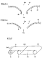
- FIG. 7 is a perspective view showing a process for manufacturing a press felt according to the invention.
- FIG. 8 is a perspective view showing another process for manufacturing a press felt according to the invention.
- FIG. 9 is a perspective view showing still another process for manufacturing a press felt according to the invention.
- FIG. 10 is a schematic view of an apparatus for con- firming the effect of a press felt according to the invention.
- FIG. 11 is a schematic view of another apparatus for confirming the effect of a press felt according to the invention.
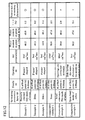
- FIG. 12 is a table of experimental results
- FIG. 13 is a schematic explanatory view of a press apparatus in a papermaking machine
- FIG. 14 is an explanatory view illustrating the movement of water in a wet paper web.
- FIG. 15 is a cross-sectional view of a conventional press felt.
- press felt 10 comprises a base body 30, and batt layers 20 which comprise short fiber and a rewetting prevention layer 40 to be described below.
- the layers are intertwined by needle punching to form an integrated press felt.
- the base body 30 is provided to impart strength to the press felt.
- the material of the base body may be a woven fabric or a belt-shaped body composed of yarns which are not woven.
- a batt layer 20 is provided between the rewetting prevention layer 40 and the base body 30.
- the rewetting prevention layer 40 and the base body 30 can be in direct contact with each other.
- passage 44 is one of many passages provided in the rewetting prevention layer 40.
- Passage 44 is funnel-shaped so that its wet paper web side opening 42a is larger than its press roll side opening 42b.
- the rewetting prevention layer 40 comprises a thin film, originally without holes, and is attached to the main body of the felt 10 by needle punching, whereby short fibers of the batt are inserted through the film.
- the passage 44 As the fibers of the batt layer are inserted into the rewetting prevention layer 40 by needle punching, the passage 44 is produced, and a rim 42 of the opening protrudes downward.
- the passage 44 has a three-dimensional structure, in which the rim 42 has the roll side opening 42b formed at its lower end, and the wet paper web side opening 42a formed at its upper end. The inclination of the wall of the rim 42 causes the wet paper web side opening 42a to be larger than the roll side opening 42b.
- a biaxially oriented film is suitable for use as a rewetting prevention layer 40.
- Films exhibiting low water absorption such as polyethylene, polypropylene, polyvinylidene and polyester, and also water-absorbing films such as nylon and polyurethane, may be used as a film material.
- the rewetting prevention layer preferably comprises a material which has an extension characteristic similar to that of the base body or the batt layer in order to match the extension characteristics of components of the felt 10, and thereby improve its heat resistance when it is subjected to heating in the felt manufacturing process.
- nylon is frequently used for the batt layer 20 and the base body 30 of a papermaking press felt 10. Where nylon is used to form the batt layer and/or the base body, the film is also preferably made of nylon.
- a preferred rewetting prevention layer is one having a thickness in the range of 10 to 30 ⁇ m, a tensile strength in the range from 1 to 15 kg/cm in the length and breath directions respectively, and a fracture elongation in the range of about 50% to 200% was preferable.
- FIG. 3 arrows show the directions of movement of water in the operation of the press felt when carrying a wet paper web through the nip of a press roll.
- Water from the wet paper web moves into the press felt 10 as a result of the nip pressure.
- the water squeezed from the surface of the felt passes through the passage 44 in the rewetting prevention layer 40, and moves to the roll surface side.
- the water flows smoothly through the passage 44, since the passage is tapered.
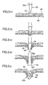
- FIG. 4 is an enlarged view of the point of a needle 50 used in the manufacturing process and FIGs. 5(A) - 5(E) show the successive stages of the punching operation in which an opening is produced in the rewetting prevention layer.
- a good result may be obtained if a needle 50 which has a ball point 51 shown in FIG. 4 is used.
- This ball point 51 is formed in a spherical shape at the point of the needle 50. It has been confirmed by experiment that the spherical part of ball point 51 preferably has a radius in the range from 0.05 mm to 0.09 mm.
- the main body of the needle 50 is polygon-shaped in transverse cross section, and barbs 52a for catching and pushing short fibers are formed along corners 52 of the polygon.
- barbs 52a for catching and pushing short fibers are formed along corners 52 of the polygon.
- the needle 50 which is triangular in transverse cross-section, has barbs 52a formed along all three corners 52.
- a layer of short fibers is placed on the rewetting prevention layer 40.
- a needle 50 is driven into the upper part of the layer of short fibers.
- the ball point 51 of the needle 50 passes through the short fibers and reaches the rewetting prevention layer 40 as shown in FIG. 5(B). Since the area of ball point 51 which comes into contact with the rewetting prevention layer 40 is large, the needle 50 does not punch the rewetting prevention layer 40 immediately, but instead depresses the layer 40 downward at first.
- the rewetting prevention layer 40 is ruptured to form a hole, as shown in FIG. 5(C).
- the roll side opening 42b is formed.
- the part which is ruptured is depressed downward as the needle 50 advances, forming a cylindrical opening 46, conforming to the shape of the point length portion 53 of the needle.
- the barb 52a catches short fibers and pushes them below the rewetting prevention layer 40 . If the barbs 52a are provided in two or more corners 52, more short fiber are pushed downward. As a result of the movement of the short fibers, a depressed and inclined opening rim 42 is formed in the rewetting prevention layer 40. In this way, as shown in FIG. 5(E), a passage 44, in which the wet paper web side opening 42a is larger than the roll side opening 42b, is formed in the rewetting prevention layer 40.
- the needle 50 After the needle 50 is depressed to a prescribed position, it is moved up again.
- the rewetting prevention layer 40 is then moved horizontally through a prescribed distance, and the needle 50 again moves downward so that short fibers are driven into the rewetting prevention layer 40. This operation is repeated until the desired pattern of passages is formed.
- the passage 44 is formed in the re-wetting prevnetion layer 40.
- the re-wetting prevention layer 40 and the opening rim 42 around the wet paper web side opening 42a may be prevented from being split largely by the impact of punching and thus the passage 44 may be prevented from being united each other which will result in the film rupture.
- the needling process is carried out by causing a needle board (not shown), having many needles 50, to reciprocate up and down. It is acceptable to drive the short fibers into the rewetting prevention layer 40, and to form the openings 44, by means of needles 50 all of which are of the same kind and of the same thickness. On the other hand, it is also possible to provide a needle array in which needles of various kinds are arranged on a single needle board according to control parameters such as air permeability, etc. in order to achieve a desired performance in the papermaking felt.
- additional needles can be provided on the same needle board together with needles 50 having ball points 51 and barbs 52a formed on all corners 52.
- the additional needles may be thicker than the other needles, and may have sharp points and barbs only on one corner.
- three dimensional passages 44 which have a wet paper web side opening 42a larger than the roll side opening 42b, are provided along with additional openings (not shown) which are larger than this passage 44 and of generally configuration.
- a rewetting prevention layer 40 having a passage 44 is provided.
- barbs 52a are provided along all corners 52 of each needle 50.
- a cylindrical opening 46 is formed at the inner edge of the opening rim 42 by the needle 50 as described above. Since the passage 44 as a whole has a funnel shape, it easily prevents infiltration of water from the roll side opening 42b.
- FIG. 6(B) depicts a passage 44' formed by a needle 50 which has the usual sharp point rather than a ball point 51.
- the short fibers drawn by barbs 52a into the rewetting prevention layer 40 form an inclined passage rim 42, no cylindrical opening corresponding to opening 46 in FIG. 6(A) is formed.
- the passage of FIG. 6(A) is inferior in its rewetting prevention ability to a passage 44 having a cylindrical opening 46. However, it may be adopted when improved productivity is important.
- the opening rim 42 inclines and protrudes downward more easily since the rim 42 of the passage is supported by the short fiber bed on the lower side of the rewetting prevention layer 40.
- the impact of needle punching is eased by the lower short fiber bed, and, as a result, rupture of the rewetting prevention layer 40 occurs more reliably.
- passages 44 in which the wet paper web side openings 42a are larger than the roll side openings 42b, may be manufactured more easily.
- a short fiber bed is arranged on a base body 30, and both are integrated by needle punching. Then, the base body 30 is turned upside down. In this situation, the base body 30, and a batt layer 20 on the roll side, have been already formed.
- the wet paper web side is formed next, and methods for forming the wet paper web side can be divided roughly into two general patterns, either of which may be adopted.
- a rewetting prevention layer 40 and a short fiber bed are accumulated on a base body 30 sequentially, and are integrated with the base body 30 by needle punching.
- a bed of short fibers is provided on a rewetting prevention layer 40 and, by integrating the fiber bed with the rewetting prevention layer by needle punching, a preparation layer 60 is obtained.
- the preparation layer 60 is then arranged on a base body 30, and the preparation layer and base body are integrated by needle punching.
- a rewetting prevention layer 40 or a preparation layer 60 on a base body 30 will be explained with reference to FIGs. 7 - 9.
- the rewetting prevention layer 40, or the preparation layer 60 is provided on a material roll 70, and the base body is stretched between stretch rolls 80.
- the rewetting prevention layer 40, or preparation layer 60 has the same width in the cross machine direction (CMD) as the base body 30.
- CMD cross machine direction
- a leading edge of the rewetting prevention layer 40, or preparation layer 60, is first fixed on the base body 30.
- the layer 40 or 60 is drawn from the material roll 70 as the base body 30 moves around stretch rolls 80. After the layer 40 or 60 is placed on the base body 30, it is severed at almost the same position at which the leading edge is fixed to the base body 30, and the severed end is also fixed on the base body.
- FIGs. 8 and 9 show manufacturing methods in which the rewetting prevention layer 40 has a width less than that of the base body 30 in the cross machine direction.
- the rewetting prevention layer 40, or preparation layer 60 is rolled onto the base body 30 at a small angle relative to the machine direction so that it is wound onto the base body in a spiral.
- the layer 40 or 60 may be arranged so that its lengthwise direction is at a small angle relative to the cross machine direction of the base body 30.
- layer 40 With the longitudinal direction of the rewetting prevention layer 40 disposed at an appropriate small angle relative to the cross machine direction of the base body 30, layer 40 is placed on the base body so that a length of layer 40 extends from a first edge of the base body to the other edge. Then, the rewetting prevention layer 40 is folded and is placed on the base body so that it extends toward the first edge.
- the rewetting prevention layer 40 may have a structure with improved air permeability depending on the desired characteristics of the papermaking felt.
- the holes for improving air permeability of the layer 40 may be punched preliminarily in the layer by the use of needles.
- the needles each had a ball point 51 is at the point, a triangular cross-section, and barbs 52a formed along all the corners 52.
- the rewetting prevention layer 40 was composed of a biaxially oriented film made of nylon.
- the radius of the ball point 51 of the needles was 0.09 mm.
- the opening 44 was funnel-shaped. Air permeability was 6cc/cm 2 /sec.
- the rewetting prevention layer 40 was composed of a biaxially oriented film made of nylon.
- the radius of the ball point 51 of the needles was 0.075 mm.
- the opening 44 was funnel-shaped. Air permeability was 5cc/cm 2 /sec.
- the rewetting prevention layer 40 was composed of a biaxially oriented film made of nylon.
- the radius of the ball point 51 of the needles was 0.05 mm.
- the opening 44 was funnel-shaped. Air permeability was 5 cc/cm 2 /sec.
- No rewetting prevention layer 40 was used.
- the radius of the ball point 51 of the punching needles was 0.09 mm.
- Air permeability was 15 cc/cm 2 /sec.
- a rewetting prevention layer 40 was composed of an axial extension film made of nylon.
- the radius of the ball point 51 of the needles was 0.09 mm. Tears in the direction of the film extension were present to a marked extent, and the openings were mutually connected to one another Air permeability was 10 cc/cm 2 /sec.
- the rewetting prevention layer 40 was a spun bond layer made of nylon.
- the radius of the ball point 51 of the needles was 0.09 mm.
- the punched openings were flat and of the same thickness as the needles. Air permeability was 5 cc/cm 2 /sec.
- the felt of each of the examples was used as a bottom side felt 10.
- the top side felt 110 was the same as described above in connection with Comparative example 1.
- Both apparatuses shown in FIGs. 10 and 11 had a running speed of 500 m/min and a press pressure of 100 kg/cm 2 .
- a larger area of the bottom side felt 10 is in contact with the lower press roll, and the wet paper web is in contact with felts 10 and 110 after release from the nip pressure only for a very short time. So, if the water content of the wet paper web is measured at the press exit, data on the water content of the wet paper web, in which rewetting has occurred to a lesser degree, may be obtained. Accordingly, the degree of rewetting in a given felt can be evaluated by comparing the water content in identical felts passing through the two apparatuses.
- FIG. 12 A summary of the experimental results is shown in FIG. 12. As shown in FIG. 12, it has been confirmed that the papermaking press felts according to the invention exhibit excellent suppression of the rewetting phenomenon.
- the invention makes it possible to provide a papermaking press felt which has a comparatively simple structure and good rewetting suppression.
Applications Claiming Priority (2)
| Application Number | Priority Date | Filing Date | Title |
|---|---|---|---|
| JP2001279817A JP2003089990A (ja) | 2001-09-14 | 2001-09-14 | 抄紙用プレスフェルト |
| JP2001279817 | 2001-09-14 |
Publications (2)
| Publication Number | Publication Date |
|---|---|
| EP1293602A1 true EP1293602A1 (de) | 2003-03-19 |
| EP1293602B1 EP1293602B1 (de) | 2006-12-27 |
Family
ID=19103925
Family Applications (1)
| Application Number | Title | Priority Date | Filing Date |
|---|---|---|---|
| EP02256294A Expired - Lifetime EP1293602B1 (de) | 2001-09-14 | 2002-09-11 | Pressfilz für die Papierherstellung |
Country Status (6)
| Country | Link |
|---|---|
| US (1) | US6716318B2 (de) |
| EP (1) | EP1293602B1 (de) |
| JP (1) | JP2003089990A (de) |
| CN (1) | CN1231635C (de) |
| CA (1) | CA2402661C (de) |
| DE (1) | DE60217035T2 (de) |
Cited By (12)
| Publication number | Priority date | Publication date | Assignee | Title |
|---|---|---|---|---|
| WO2004033790A1 (en) * | 2002-10-10 | 2004-04-22 | Albany International Corp. | Anti-rewet press fabric |
| WO2005075736A2 (en) | 2004-01-30 | 2005-08-18 | Voith Paper Patent Gmbh | Advanced dewatering system |
| EP1674613A1 (de) * | 2004-12-23 | 2006-06-28 | Voith Fabrics Patent GmbH | Pressfilz für eine Papiermaschine |
| EP1722034A1 (de) * | 2005-05-10 | 2006-11-15 | Voith Patent GmbH | PMC mit splittbaren Fasern |
| US7476293B2 (en) | 2004-10-26 | 2009-01-13 | Voith Patent Gmbh | Advanced dewatering system |
| US7476294B2 (en) | 2004-10-26 | 2009-01-13 | Voith Patent Gmbh | Press section and permeable belt in a paper machine |
| US7510631B2 (en) | 2004-10-26 | 2009-03-31 | Voith Patent Gmbh | Advanced dewatering system |
| US7524403B2 (en) | 2006-04-28 | 2009-04-28 | Voith Paper Patent Gmbh | Forming fabric and/or tissue molding belt and/or molding belt for use on an ATMOS system |
| US7527709B2 (en) | 2006-03-14 | 2009-05-05 | Voith Paper Patent Gmbh | High tension permeable belt for an ATMOS system and press section of paper machine using the permeable belt |
| US7550061B2 (en) | 2006-04-28 | 2009-06-23 | Voith Paper Patent Gmbh | Dewatering tissue press fabric for an ATMOS system and press section of a paper machine using the dewatering fabric |
| US7686923B2 (en) | 2004-01-30 | 2010-03-30 | Voith Patent Gmbh | Paper machine dewatering system |
| US7744726B2 (en) | 2006-04-14 | 2010-06-29 | Voith Patent Gmbh | Twin wire for an ATMOS system |
Families Citing this family (8)
| Publication number | Priority date | Publication date | Assignee | Title |
|---|---|---|---|---|
| GB0204308D0 (en) * | 2002-02-23 | 2002-04-10 | Voith Fabrics Heidenheim Gmbh | Papermachine clothing |
| JP4133433B2 (ja) * | 2003-02-26 | 2008-08-13 | イチカワ株式会社 | 抄紙用プレスフェルト |
| WO2005061787A1 (en) * | 2003-12-11 | 2005-07-07 | Albany International Corp. | Passive sensor system for detection or wear problems in paper machine clothing |
| US7297233B2 (en) * | 2004-01-30 | 2007-11-20 | Voith Paper Patent Gmbh | Dewatering apparatus in a paper machine |
| US20050167067A1 (en) * | 2004-01-30 | 2005-08-04 | Bob Crook | Dewatering fabric in a paper machine |
| US20090038174A1 (en) * | 2007-08-07 | 2009-02-12 | Dar-Style Consultants & More Ltd. | Kitchen utensil dryer |
| WO2018022586A1 (en) * | 2016-07-28 | 2018-02-01 | Kimberly-Clark Worldwide, Inc. | Three-dimensional papermaking belt |
| US11098450B2 (en) | 2017-10-27 | 2021-08-24 | Albany International Corp. | Methods for making improved cellulosic products using novel press felts and products made therefrom |
Citations (2)
| Publication number | Priority date | Publication date | Assignee | Title |
|---|---|---|---|---|
| EP0439280A1 (de) * | 1990-01-22 | 1991-07-31 | Appleton Mills | Struktur zum Entwässern von Papierbahnen in einem Papierherstellungsprozess |
| US5372876A (en) * | 1993-06-02 | 1994-12-13 | Appleton Mills | Papermaking felt with hydrophobic layer |
Family Cites Families (8)
| Publication number | Priority date | Publication date | Assignee | Title |
|---|---|---|---|---|
| SE429769B (sv) * | 1980-04-01 | 1983-09-26 | Nordiskafilt Ab | Arkaggregat och sett att tillverka detsamma |
| FI64960C (fi) * | 1982-10-08 | 1984-02-10 | Tamfelt Oy Ab | Transportfilt foer papperstillverkning och foerfarande foer des tillverkning |
| DE3426264A1 (de) * | 1984-07-17 | 1986-01-30 | Franz F. 5160 Düren Kufferath | Entwaeserungsband fuer pressen in der nasspartie einer papiermaschine |
| US4806413A (en) * | 1986-03-26 | 1989-02-21 | Asten Group, Inc. | Papermaker's felt containing scrim material |
| EP0346307A3 (de) | 1988-06-09 | 1991-03-06 | Nordiskafilt Ab | Nassfilz für Papiermaschine |
| US4830905A (en) | 1988-08-22 | 1989-05-16 | Appleton Mills | Papermaker's felt incorporating a closed cell polymeric foam layer |
| US5445746A (en) * | 1992-08-28 | 1995-08-29 | Cer-Wat Corporation | Method for dewatering a porous wet web |
| JPH1150386A (ja) * | 1997-06-30 | 1999-02-23 | Christian Schiel | 改善された両面構造を有する抄紙用フェルト及びその製造方法 |
-
2001
- 2001-09-14 JP JP2001279817A patent/JP2003089990A/ja not_active Withdrawn
-
2002
- 2002-09-09 US US10/237,890 patent/US6716318B2/en not_active Expired - Fee Related
- 2002-09-11 CN CNB02131635XA patent/CN1231635C/zh not_active Expired - Fee Related
- 2002-09-11 CA CA002402661A patent/CA2402661C/en not_active Expired - Fee Related
- 2002-09-11 EP EP02256294A patent/EP1293602B1/de not_active Expired - Lifetime
- 2002-09-11 DE DE60217035T patent/DE60217035T2/de not_active Expired - Lifetime
Patent Citations (2)
| Publication number | Priority date | Publication date | Assignee | Title |
|---|---|---|---|---|
| EP0439280A1 (de) * | 1990-01-22 | 1991-07-31 | Appleton Mills | Struktur zum Entwässern von Papierbahnen in einem Papierherstellungsprozess |
| US5372876A (en) * | 1993-06-02 | 1994-12-13 | Appleton Mills | Papermaking felt with hydrophobic layer |
Cited By (24)
| Publication number | Priority date | Publication date | Assignee | Title |
|---|---|---|---|---|
| US7128810B2 (en) | 2002-10-10 | 2006-10-31 | Albany International Corp. | Anti-rewet press fabric |
| WO2004033790A1 (en) * | 2002-10-10 | 2004-04-22 | Albany International Corp. | Anti-rewet press fabric |
| US7931781B2 (en) * | 2004-01-30 | 2011-04-26 | Voith Patent Gmbh | Advanced dewatering system |
| WO2005075736A2 (en) | 2004-01-30 | 2005-08-18 | Voith Paper Patent Gmbh | Advanced dewatering system |
| US8236140B2 (en) | 2004-01-30 | 2012-08-07 | Voith Patent Gmbh | Advanced dewatering system |
| CN1934312B (zh) * | 2004-01-30 | 2010-12-22 | 沃依特专利有限责任公司 | 高级脱水体系 |
| EP2000587A1 (de) * | 2004-01-30 | 2008-12-10 | Voith Patent GmbH | Entwässerungssystem |
| WO2005075736A3 (en) * | 2004-01-30 | 2005-10-06 | Voith Fabrics Patent Gmbh | Advanced dewatering system |
| US8608909B2 (en) | 2004-01-30 | 2013-12-17 | Voith Patent Gmbh | Advanced dewatering system |
| US7686923B2 (en) | 2004-01-30 | 2010-03-30 | Voith Patent Gmbh | Paper machine dewatering system |
| US7951269B2 (en) | 2004-10-26 | 2011-05-31 | Voith Patent Gmbh | Advanced dewatering system |
| US8092652B2 (en) | 2004-10-26 | 2012-01-10 | Voith Patent Gmbh | Advanced dewatering system |
| US7476294B2 (en) | 2004-10-26 | 2009-01-13 | Voith Patent Gmbh | Press section and permeable belt in a paper machine |
| US7476293B2 (en) | 2004-10-26 | 2009-01-13 | Voith Patent Gmbh | Advanced dewatering system |
| US8118979B2 (en) | 2004-10-26 | 2012-02-21 | Voith Patent Gmbh | Advanced dewatering system |
| US7510631B2 (en) | 2004-10-26 | 2009-03-31 | Voith Patent Gmbh | Advanced dewatering system |
| US7842166B2 (en) | 2004-10-26 | 2010-11-30 | Voith Patent Gmbh | Press section and permeable belt in a paper machine |
| EP1674613A1 (de) * | 2004-12-23 | 2006-06-28 | Voith Fabrics Patent GmbH | Pressfilz für eine Papiermaschine |
| US7523531B2 (en) | 2005-05-10 | 2009-04-28 | Voith Patent Gmbh | PMC with splittable fibres |
| EP1722034A1 (de) * | 2005-05-10 | 2006-11-15 | Voith Patent GmbH | PMC mit splittbaren Fasern |
| US7527709B2 (en) | 2006-03-14 | 2009-05-05 | Voith Paper Patent Gmbh | High tension permeable belt for an ATMOS system and press section of paper machine using the permeable belt |
| US7744726B2 (en) | 2006-04-14 | 2010-06-29 | Voith Patent Gmbh | Twin wire for an ATMOS system |
| US7524403B2 (en) | 2006-04-28 | 2009-04-28 | Voith Paper Patent Gmbh | Forming fabric and/or tissue molding belt and/or molding belt for use on an ATMOS system |
| US7550061B2 (en) | 2006-04-28 | 2009-06-23 | Voith Paper Patent Gmbh | Dewatering tissue press fabric for an ATMOS system and press section of a paper machine using the dewatering fabric |
Also Published As
| Publication number | Publication date |
|---|---|
| CN1408949A (zh) | 2003-04-09 |
| CA2402661A1 (en) | 2003-03-14 |
| US6716318B2 (en) | 2004-04-06 |
| DE60217035D1 (de) | 2007-02-08 |
| EP1293602B1 (de) | 2006-12-27 |
| US20030051848A1 (en) | 2003-03-20 |
| CN1231635C (zh) | 2005-12-14 |
| DE60217035T2 (de) | 2007-04-12 |
| JP2003089990A (ja) | 2003-03-28 |
| CA2402661C (en) | 2008-07-08 |
Similar Documents
| Publication | Publication Date | Title |
|---|---|---|
| EP1293602B1 (de) | Pressfilz für die Papierherstellung | |
| JP3264461B2 (ja) | 搬送ベルト | |
| EP0878579B1 (de) | Papiermacherfilz | |
| JP4302184B2 (ja) | 改良した孔開きフィルムの製造方法、その結果得られた孔開きフィルムおよびその結果得られた孔開きフィルムを取り入れた吸収性製品 | |
| CA2446249C (en) | Papermaking press felt and press apparatus for a papermaking machine | |
| CA2302988C (en) | Press felt for making paper | |
| EP0550715A1 (de) | Papiermacherpressfilz mit einem grundgewebe, welches nicht besäumt werden muss | |
| KR101102211B1 (ko) | 습지 반송용 벨트 | |
| EP1632602A1 (de) | Papiermacherfilz mit punktuell gebundener Zwischenschicht aus Fasern geringer Feinheit | |
| CA2366917C (en) | Shoe press belt and manufacturing method | |
| EP2213789B1 (de) | Filz zur papierherstellung | |
| CA2496275A1 (en) | Anti-rewet press fabric | |
| JP4627137B2 (ja) | 湿紙搬送用ベルト | |
| US7442426B2 (en) | Press felt for papermaking | |
| US20080073052A1 (en) | Paper Transporting Felt for Shoe Press, and Press Apparatus of Shoe Press Type Paper Machine having the Paper Transporting Felt |
Legal Events
| Date | Code | Title | Description |
|---|---|---|---|
| PUAI | Public reference made under article 153(3) epc to a published international application that has entered the european phase |
Free format text: ORIGINAL CODE: 0009012 |
|
| AK | Designated contracting states |
Kind code of ref document: A1 Designated state(s): AT BE BG CH CY CZ DE DK EE ES FI FR GB GR IE IT LI LU MC NL PT SE SK TR |
|
| AX | Request for extension of the european patent |
Extension state: AL LT LV MK RO SI |
|
| 17P | Request for examination filed |
Effective date: 20030611 |
|
| AKX | Designation fees paid |
Designated state(s): DE FI SE |
|
| GRAP | Despatch of communication of intention to grant a patent |
Free format text: ORIGINAL CODE: EPIDOSNIGR1 |
|
| GRAS | Grant fee paid |
Free format text: ORIGINAL CODE: EPIDOSNIGR3 |
|
| GRAA | (expected) grant |
Free format text: ORIGINAL CODE: 0009210 |
|
| AK | Designated contracting states |
Kind code of ref document: B1 Designated state(s): DE FI SE |
|
| REF | Corresponds to: |
Ref document number: 60217035 Country of ref document: DE Date of ref document: 20070208 Kind code of ref document: P |
|
| REG | Reference to a national code |
Ref country code: SE Ref legal event code: TRGR |
|
| PLBE | No opposition filed within time limit |
Free format text: ORIGINAL CODE: 0009261 |
|
| STAA | Information on the status of an ep patent application or granted ep patent |
Free format text: STATUS: NO OPPOSITION FILED WITHIN TIME LIMIT |
|
| 26N | No opposition filed |
Effective date: 20070928 |
|
| PGFP | Annual fee paid to national office [announced via postgrant information from national office to epo] |
Ref country code: FI Payment date: 20090914 Year of fee payment: 8 Ref country code: SE Payment date: 20090910 Year of fee payment: 8 |
|
| PGFP | Annual fee paid to national office [announced via postgrant information from national office to epo] |
Ref country code: DE Payment date: 20090903 Year of fee payment: 8 |
|
| REG | Reference to a national code |
Ref country code: SE Ref legal event code: EUG |
|
| PG25 | Lapsed in a contracting state [announced via postgrant information from national office to epo] |
Ref country code: FI Free format text: LAPSE BECAUSE OF NON-PAYMENT OF DUE FEES Effective date: 20100911 |
|
| REG | Reference to a national code |
Ref country code: DE Ref legal event code: R119 Ref document number: 60217035 Country of ref document: DE Effective date: 20110401 |
|
| PG25 | Lapsed in a contracting state [announced via postgrant information from national office to epo] |
Ref country code: DE Free format text: LAPSE BECAUSE OF NON-PAYMENT OF DUE FEES Effective date: 20110401 |
|
| PG25 | Lapsed in a contracting state [announced via postgrant information from national office to epo] |
Ref country code: SE Free format text: LAPSE BECAUSE OF NON-PAYMENT OF DUE FEES Effective date: 20100912 |