EP1293582A2 - High-strength steel wire excelling in resistance to strain aging embrittlement and longitudinal cracking, and method for production thereof - Google Patents
High-strength steel wire excelling in resistance to strain aging embrittlement and longitudinal cracking, and method for production thereof Download PDFInfo
- Publication number
- EP1293582A2 EP1293582A2 EP02292034A EP02292034A EP1293582A2 EP 1293582 A2 EP1293582 A2 EP 1293582A2 EP 02292034 A EP02292034 A EP 02292034A EP 02292034 A EP02292034 A EP 02292034A EP 1293582 A2 EP1293582 A2 EP 1293582A2
- Authority
- EP
- European Patent Office
- Prior art keywords
- steel wire
- strength
- diameter
- chemical composition
- denotes
- Prior art date
- Legal status (The legal status is an assumption and is not a legal conclusion. Google has not performed a legal analysis and makes no representation as to the accuracy of the status listed.)
- Granted
Links
Images


Classifications
-
- C—CHEMISTRY; METALLURGY
- C22—METALLURGY; FERROUS OR NON-FERROUS ALLOYS; TREATMENT OF ALLOYS OR NON-FERROUS METALS
- C22C—ALLOYS
- C22C38/00—Ferrous alloys, e.g. steel alloys
- C22C38/04—Ferrous alloys, e.g. steel alloys containing manganese
-
- C—CHEMISTRY; METALLURGY
- C22—METALLURGY; FERROUS OR NON-FERROUS ALLOYS; TREATMENT OF ALLOYS OR NON-FERROUS METALS
- C22C—ALLOYS
- C22C38/00—Ferrous alloys, e.g. steel alloys
-
- B—PERFORMING OPERATIONS; TRANSPORTING
- B21—MECHANICAL METAL-WORKING WITHOUT ESSENTIALLY REMOVING MATERIAL; PUNCHING METAL
- B21C—MANUFACTURE OF METAL SHEETS, WIRE, RODS, TUBES, PROFILES OR LIKE SEMI-MANUFACTURED PRODUCTS OTHERWISE THAN BY ROLLING; AUXILIARY OPERATIONS USED IN CONNECTION WITH METAL-WORKING WITHOUT ESSENTIALLY REMOVING MATERIAL
- B21C1/00—Manufacture of metal sheets, wire, rods, tubes or like semi-manufactured products by drawing
-
- B—PERFORMING OPERATIONS; TRANSPORTING
- B21—MECHANICAL METAL-WORKING WITHOUT ESSENTIALLY REMOVING MATERIAL; PUNCHING METAL
- B21C—MANUFACTURE OF METAL SHEETS, WIRE, RODS, TUBES, PROFILES OR LIKE SEMI-MANUFACTURED PRODUCTS OTHERWISE THAN BY ROLLING; AUXILIARY OPERATIONS USED IN CONNECTION WITH METAL-WORKING WITHOUT ESSENTIALLY REMOVING MATERIAL
- B21C37/00—Manufacture of metal sheets, rods, wire, tubes, profiles or like semi-manufactured products, not otherwise provided for; Manufacture of tubes of special shape
- B21C37/04—Manufacture of metal sheets, rods, wire, tubes, profiles or like semi-manufactured products, not otherwise provided for; Manufacture of tubes of special shape of rods or wire
- B21C37/045—Manufacture of wire or rods with particular section or properties
-
- C—CHEMISTRY; METALLURGY
- C21—METALLURGY OF IRON
- C21D—MODIFYING THE PHYSICAL STRUCTURE OF FERROUS METALS; GENERAL DEVICES FOR HEAT TREATMENT OF FERROUS OR NON-FERROUS METALS OR ALLOYS; MAKING METAL MALLEABLE, e.g. BY DECARBURISATION OR TEMPERING
- C21D8/00—Modifying the physical properties of ferrous metals or ferrous alloys by deformation combined with, or followed by, heat treatment
- C21D8/06—Modifying the physical properties of ferrous metals or ferrous alloys by deformation combined with, or followed by, heat treatment during manufacturing of rods or wires
-
- C—CHEMISTRY; METALLURGY
- C22—METALLURGY; FERROUS OR NON-FERROUS ALLOYS; TREATMENT OF ALLOYS OR NON-FERROUS METALS
- C22C—ALLOYS
- C22C38/00—Ferrous alloys, e.g. steel alloys
- C22C38/02—Ferrous alloys, e.g. steel alloys containing silicon
-
- D—TEXTILES; PAPER
- D07—ROPES; CABLES OTHER THAN ELECTRIC
- D07B—ROPES OR CABLES IN GENERAL
- D07B1/00—Constructional features of ropes or cables
- D07B1/06—Ropes or cables built-up from metal wires, e.g. of section wires around a hemp core
- D07B1/0606—Reinforcing cords for rubber or plastic articles
- D07B1/066—Reinforcing cords for rubber or plastic articles the wires being made from special alloy or special steel composition
-
- D—TEXTILES; PAPER
- D07—ROPES; CABLES OTHER THAN ELECTRIC
- D07B—ROPES OR CABLES IN GENERAL
- D07B2205/00—Rope or cable materials
- D07B2205/30—Inorganic materials
- D07B2205/3021—Metals
- D07B2205/3025—Steel
- D07B2205/3046—Steel characterised by the carbon content
- D07B2205/3057—Steel characterised by the carbon content having a high carbon content, e.g. greater than 0,8 percent respectively SHT or UHT wires
-
- Y—GENERAL TAGGING OF NEW TECHNOLOGICAL DEVELOPMENTS; GENERAL TAGGING OF CROSS-SECTIONAL TECHNOLOGIES SPANNING OVER SEVERAL SECTIONS OF THE IPC; TECHNICAL SUBJECTS COVERED BY FORMER USPC CROSS-REFERENCE ART COLLECTIONS [XRACs] AND DIGESTS
- Y10—TECHNICAL SUBJECTS COVERED BY FORMER USPC
- Y10T—TECHNICAL SUBJECTS COVERED BY FORMER US CLASSIFICATION
- Y10T428/00—Stock material or miscellaneous articles
- Y10T428/12—All metal or with adjacent metals
- Y10T428/12431—Foil or filament smaller than 6 mils
Definitions
- the present invention relates to a high-strength steel wire and a method for production thereof, said steel wire being one which is ready for shipment without heat treatment (such as blueing) after cold working and which finds use for steel cords and wire ropes.
- Automotive steel tires are reinforced with steel cords or bead wires, which are composed of very thin steel wires twisted together, each being about 0.15 to 0.4 mm in diameter and having high strength in excess of 310 kgf/cm 2 .
- Said steel wire is produced from a hot-rolled wire rod of high-carbon steel (eutectoid steel or hyper-eutectoid steel) by drawing (for reduction in diameter), patenting, acid pickling, brass plating (for metal lubrication), and final wet cold drawing.
- the resulting steel wire is as thin as about 0.2 mm in diameter.
- the patenting step is carried out at about 500-550°C so as to transform the austenite structure into the uniform, fine pearlite structure, thereby imparting toughness to the steel wire.
- Recent automotive tires are required to have improved durability, and steel wires for tire cords are required to have higher strength than before.
- Steel wires can be improved in strength readily by increasing the carbon content.
- high strength should be accompanied by sufficient ductility. Any attempt to improve strength without respect to ductility ends up with a problem with longitudinal cracking -- fracture that occurs in the lengthwise direction upon twisting.
- Japanese Patent Publication No. 99746/1994 discloses a steel incorporated with Cr and Co which make the pearlite lamellar structure fine.
- Japanese Patent Laid-open No. 99312/1997 discloses a method of drawing a steel wire continuously through a die in such a way that the reduction of area is controlled in response to the amount of strain due to drawing.
- Japanese Patent Laid-open No. 121199/1998 discloses a steel wire composed mainly of fine pearlite, with its lamellar cementite rendered amorphous.
- Japanese Patent Laid-open No. 199980/1999 discloses a steel wire having the pearlite structure such that ferrite contains no more than 1.5 atom% of carbon dissolved therein.
- Japanese Patent Laid-open No. 269607/1999 discloses a steel wire in which the amount of cementite is controlled in response to the amount of carbon and the average particle diameter of cementite is 2-10 nm.
- the present invention was completed in view of the foregoing problem. It is an object of the present invention to provide a high-strength steel wire and a method for production thereof, said steel wire having high strength as well as sufficient ductility and excelling in resistance to strain aging embrittlement and longitudinal cracking.
- Fig. 1 is a sectional view of the drawing die with reference numbers.
- Fig. 2 is a graph showing how the steel wire of the present invention (after final drawing) changes in tensile strength (in MPa) in response to diameter (D mm).
- Fig. 3 is a graph showing how the steel wire of the present invention (after final drawing) changes in tensile strength (in MPa) in response to carbon content (mass%).
- Tensile strength herein is its lower limit expressed by 3500 ⁇ D -0.145 , where D denotes the diameter.
- the present invention is based on the present inventor's finding that a high-strength high-carbon steel wire excelling in resistance to strain aging embrittlement is obtained if a high-carbon steel wire is drawn adequately and so conditioned as to impart a specific structure and a specific magnitude of strength determined by the wire diameter and carbon content.
- the present invention is based also on the finding that resistance to longitudinal cracking develops when cementite exists in amorphous form and resistance to strain aging develops when cold wet drawing is so performed as to minimize strain aging.
- the first aspect of the present invention resides in a high-strength high-carbon steel wire which is characterized by having a chemical composition (in mass%) including
- the second aspect of the present invention resides in a method of producing a high-strength steel wire by drawing a hot-rolled wire rod, subjecting the drawn wire to patenting and acid pickling, forming thereon a metal lubricating film whose main phase is composed of at least one of Cu, Ni, and Zn or an alloy thereof, and performing final drawing to reduce the diameter(D) to 0.15-0.4 mm, wherein the steel wire has the chemical composition specified above, the patenting treatment is carried out under the condition that the treated steel wire has a tensile strength no lower than (540 ⁇ [C] + 1055) MPa and no higher than (540 x [C] + 1065) MPa, where [C] denotes C content in %, and the final drawing is either cold wet drawing for a pass which results in a true strain ( ⁇ ) in excess of 2.0 or drawing through a diamond die for a pass which results in a true strain ( ⁇ ) in excess of 3.0, said drawing being so carried out as to satisfy at least two of the following
- the high-strength steel wire according to the present invention is characterized by having a chemical composition (in mass%) including
- Carbon is an inexpensive element and yet effectively contributes to strength. Carbon increases the amount of work hardening at the time of drawing and also increases strength after drawing in proportion to its content. With an excessively low carbon content, the resulting steel wire will contain ferrite more than necessary. Thus, the present invention requires the lower limit of carbon content to be 0.75%, preferably 0.80%. With an excessively high carbon content, the resulting steel wire is liable to fracture at the time of drawing owing to precipitation of net-like pro-eutectoid cementite in austenite boundaries, and the finished fine steel wire has extremely poor toughness and ductility. Thus, the present invention requires the upper limit of carbon content to be 1.20%, preferably 1.10%.
- Silicon functions as an effective deoxidizing agent.
- silicon plays an important role.
- the present invention requires the lower limit of silicon content to be 0.1%. Silicon in an amount less than 0.1% does not fully produce its deoxidizing effect.
- the present invention requires the upper limit of silicon content to be 1.5%, preferably 1.0%, and more preferably 0.5%. Silicon in an excess amount presents difficulties in wire drawing by mechanical descaling (MD for short hereinafter).
- Manganese also functions as an effective deoxidizing agent like silicon.
- manganese should be used in combination with silicon for complete deoxidizing.
- Manganese combines with sulfur in steel to form MnS, thereby improving the toughness and ductility of steel. It also improves the hardenability of steel and decreases the amount of pro-eutectoid cementite in rolled products.
- the present invention requires the lower limit of manganese content to be 0.3%, preferably 0.4%.
- manganese is liable to segregation and hence manganese in an excess amount gives rise to super-cooled structure, such as martensite and bainite, in the region of manganese segregation, thereby deteriorating drawability.
- the present invention requires the upper limit of manganese content to be 1.2%, preferably 1.0%.
- impurity elements should be as little as possible because they deteriorate ductility. Therefore, the upper limit of the content of these elements is specified as above.
- nitrogen combines with boron (mentioned later) to form BN, thereby reducing the amount of dissolved boron.
- the nitrogen content should be no more than 0.0050%, preferably no more than 0.0035%.
- Aluminum functions as an effective deoxidizing agent. It forms Al 2 O 3 . This non-metallic inclusion deteriorates ductility and seriously impedes drawability. Therefore, the present invention requires the aluminum content to be no more than 0.005%.
- the steel wire of the present invention contains, in addition to the above-mentioned components, iron (as the remainder) and inevitable impurities. For improvement in quality, it may be incorporated with one or more additional components selected from the following in an amount not harmful to the effects and functions of the basic components.
- additional components selected from the following in an amount not harmful to the effects and functions of the basic components.
- the lower limit of their content should be 0.10%. With an amount less than this limit, they do not produce their effects.
- the upper limit of their content should be 1.0% (for Ni and Cr) and 0.5% (for Mn) because their effect levels off when they are added in excess of their upper limit. In particular, Cr in an excess amount tends to form undissolved cementite, thereby causing steel to take a prolonged time to complete transformation. Moreover, it would give rise to super-cooled structure, such as martensite and bainite, in the hot-rolled wire rod.
- Copper imparts good corrosion resistance to fine steel wires, improves descalability, and prevents die seizure.
- the lower limit of copper content for desired effects should be 0.05%, and the upper limit of copper content without adverse effects should be 0.20%, preferably 0.10%.
- Copper added in an excess amount causes blistering to the surface of wire rod when the hot-rolled wire rod is rested even though the resting temperature is as high as about 900°C. Blistering forms magnetite in the steel under blisters, deteriorating mechanical descalability.
- copper reacts with sulfur to segregate CuS in grain boundaries, thereby causing flaws to the ingot and wire rod during production of steel wire.
- Cobalt suppresses the formation of pro-eutectoid cementite, thereby improving ductility and drawability.
- the lower limit of cobalt content should be 2.0%. Cobalt added in an excess amount makes patenting to take a longer time for pearlite transformation, thereby reducing productivity.
- Free boron (in the form of solid solution) suppresses the formation of ferrite.
- the lower limit of boron content (as total boron) necessary to ensure free boron is 0.0003%.
- the upper limit of boron content is 0.0050%, preferably 0.0040%. Boron added in an excess amount forms Fe 23 (CB) 6 , thereby impeding drawability. Boron that suppresses the formation of ferrite is not added boron but free boron which forms no compounds in steel. For boron to remain free, it should not form BN.
- the nitrogen content according to the present invention is no more than 0.0085, preferably no more than 0.0050%, and more preferably no more than 0.0035%, it is possible to ensure as much free boron as necessary. Free boron in an amount of at least 0.0003% is necessary to prevent the formation of ferrite; however, the upper limit of free boron is determined naturally by the amount of boron added.
- the steel wire of the present invention has a worked pearlite structure in which the lamellar cementite is amorphous.
- the pearlite structure is most suitable for drawing among the structures of steel materials. In other words, it is most suitable for fine steel wires (0.15-0.4 mm in diameter) as specified in the present invention.
- the fact that the lamellar cementite in the pearlite structure is amorphous contributes to high toughness and good ductility and hence improves resistance to longitudinal cracking even though the steel wire has high strength.
- the final drawing employs cold wet drawing for true strain ( ⁇ ) greater than 2.0 or drawing through a diamond die for true strain ( ⁇ ) greater than 3.0.
- the steel wire of the present invention has a metal lubricating film formed thereon.
- This film is a residue of the metal lubricant applied to the steel wire after patenting and before final drawing.
- the lubricant is necessary to protect the die from wearing and deterioration during drawing involving intensive working.
- the metal lubricating film may be formed by plating with Cu, Zn, or Ni (for economical reason) or from an alloy thereof (such as brass). Incidentally, brass or copper plated film helps the steel wire used as tire cords to adhere to rubber.
- the steel wire of the present invention should have a specific tensile strength (TS) no lower than (3500 ⁇ D -0.145 ) MPa and no higher than (3500 ⁇ D -0.145 + 87 ⁇ [C] -5 ) MPa, where [C] denotes the carbon content in mass%.
- TS specific tensile strength
- the range of TS was established on the basis of the following facts which are shown in Examples given later. With TS smaller than the lower limit, the steel wire has good resistance to longitudinal cracking immediately after final drawing but becomes liable to longitudinal cracking with the lapse of time owing to strain aging embrittlement.
- the steel wire is much liable to longitudinal cracking immediately after final drawing or eventually suffers longitudinal cracking with the lapse of time owing to strain aging embrittlement.
- the upper limit of TS depends on the amount of carbon in the steel wire. The reason why the lower limit of TS is not affected by carbon content is that resistance to longitudinal cracking is affected more strongly by wire diameter than by carbon content. On the other hand, the reason why the upper limit of TS is affected by carbon content is that resistance to strain aging is strongly affected by carbon content in the base metal.
- the steel wire of the present invention is produced by the process which is explained in the following.
- the process starts with preparation of an ingot having the chemical composition mentioned above.
- the ingot is made into billets by blooming.
- the billet is hot-rolled to give a steel wire rod.
- the wire rod undergoes intermediate patenting and intermediate drawing to give a steel wire which has a diameter suitable for final drawing.
- the steel wire undergoes final patenting and acid pickling and coated with a metal lubricating film.
- the steel wire is drawn into a thin steel wire (0.15-4.0 mm in diameter) by cold wet drawing as the final drawing.
- the final drawing consists of sequential steps of passing the steel wire (which has undergone final patenting) through a series of dies until the drawn wire has a desired diameter (0.15-4.0 mm).
- the hot-rolled wire rod should have a diameter of about 3.5-10 mm. It will be poor in productivity if it is thinner than 3.5 mm, and it will be poor in drawability if it is thicker than 10 mm.
- the steel wire which undergone intermediate drawing (or patenting) should have a diameter of about 1.0-2.5 mm. It will present difficulties in drawability in final drawing if it is thinner than 1.0 mm, and it will present difficulties in patenting (to control the structure down to the center of the steel wire) if it is thicker than 2.5 mm. The latter case leads to poor drawability.
- the patenting is heat treatment to make the structure into fine pearlite.
- This heat treatment is accomplished by keeping the steel wire at the austenitizing temperature and then keeping it at the transformation temperature after cooling.
- the austenitizing temperature should preferably be about 850-1050°C. Heat treatment below 850°C will not bring about austenitizing readily; heat treatment above 1050°C forms surface scale and makes crystal grains coarser, thereby deteriorating drawability.
- the austenitizing step should last for 10-75 seconds. Duration shorter than 10 seconds is not enough for complete heating; duration longer than 75 seconds is detrimental to drawability due to formation of surface scale and coarsening of crystal grain.
- the transformation temperature should be about 550-565°C.
- Heating below 550°C makes bainite dominant in the structure, which leads to poor drawability. Heating above 565°C prevents the formation of fine pearlite, decreasing the strength of the steel wire after patenting, with the result that the steel wire after final drawing lacks desired strength. Heating at 550-565°C for about 10-80 seconds permits the steel wire to have strength in a narrow range from (540 ⁇ [C] + 1050) MPa to (540°C [C] +1065) MPa in response to the carbon content [C]. This means that the steel wire can be made into fine steel wire in a stable manner by final drawing.
- the final drawing is accomplished by cold wet drawing so that the lamellar cementite of fine pearlite is made amorphous.
- the lamellar cementite can be made amorphous only when final drawing (to give a true strain ( ⁇ ) in excess of 3.0) is carried out with cooling. Therefore, cold wet drawing is employed as final drawing.
- the present invention requires that the final drawing should employ a diamond die with good heat conductivity so as to reduce heat generation due to drawing and promote decrystallization.
- the approach angle ( ⁇ ) mentioned above is the angle of the tapered surface of the approach section 2 (or reduction section) through which the steel wire is introduced into the bearing section 1 (minimum aperture section) of the die which determines the wire diameter after drawing, as shown in Fig. 1.
- the length of the bearing section mentioned above denotes the length 1 along the direction of drawing in the bearing section 2 .
- the bearing section has an inside diameter d which remains virtually unchanged along the direction of drawing.
- drawing should be carried out such that the value of VD (which is a product of D [the diameter in mm of the steel wire] and V [the drawing rate in m/min]) is no larger than 200 mm ⁇ m/min, preferably no larger than 150 mm ⁇ m/min, more preferably no larger than 100 mm ⁇ m/min.
- VD which is a product of D [the diameter in mm of the steel wire] and V [the drawing rate in m/min]
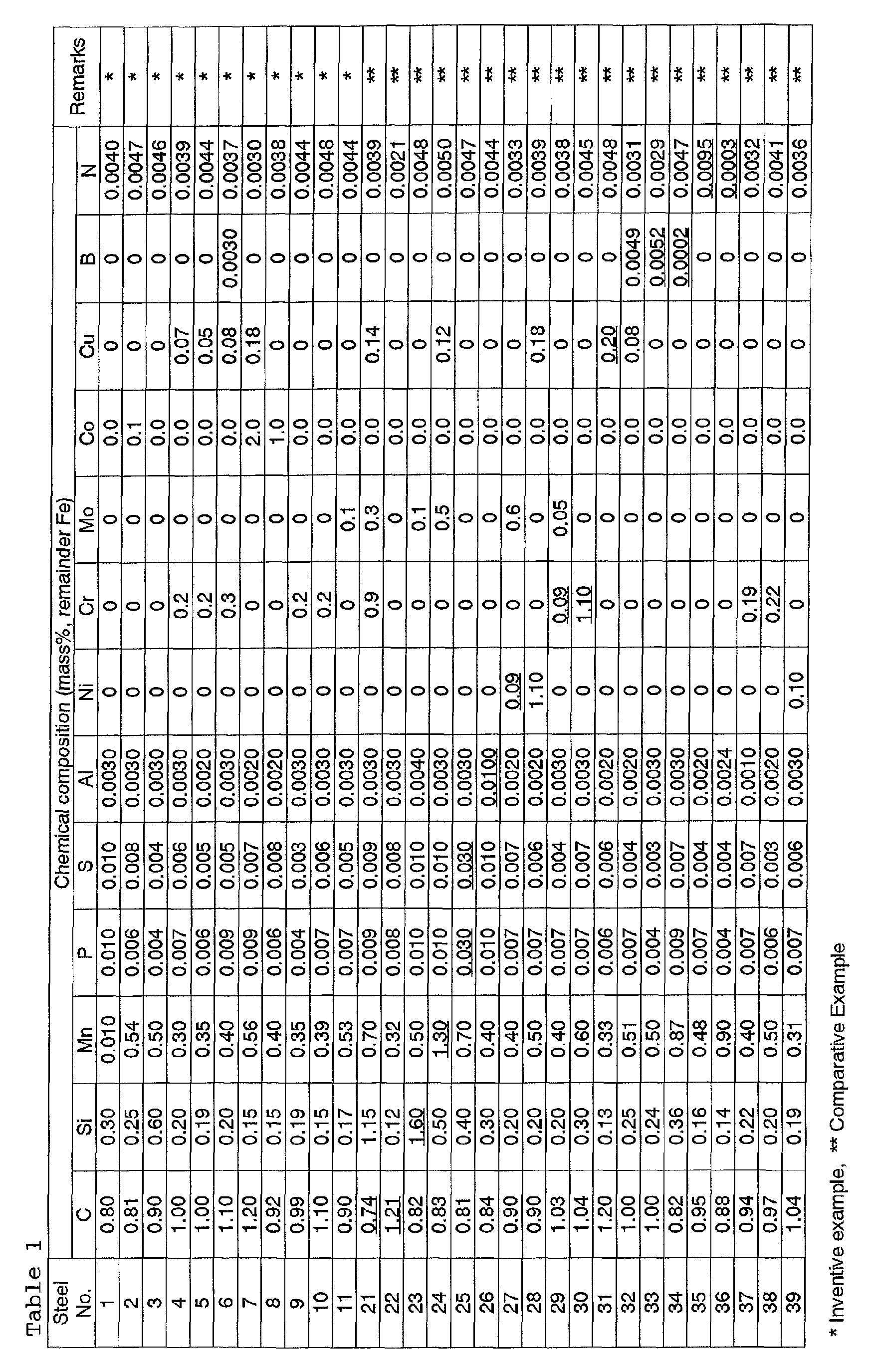
- Steel samples each having the chemical composition shown in Table 1 were prepared by converter process and ensuing secondary steelmaking. Each steel sample was made into ingots by continuous casting, and the ingot was made into billets by blooming. The billet was made into wire rods (3.5 to 10.0 mm in diameter) by hot rolling, which was followed by conditioning cooling.
- the hot-rolled wire rod underwent intermediate drawing and intermediate patenting to give a steel wire having a diameter of 1.0-2.5 mm.
- This steel wire underwent final patenting under the condition shown in Table 2.
- the resulting steel wire has tensile strength (TS) as shown in Table 2.
- TS tensile strength
- Table 2 the upper and lower limits of tensile strength specified in the present invention are also shown in Table 2.
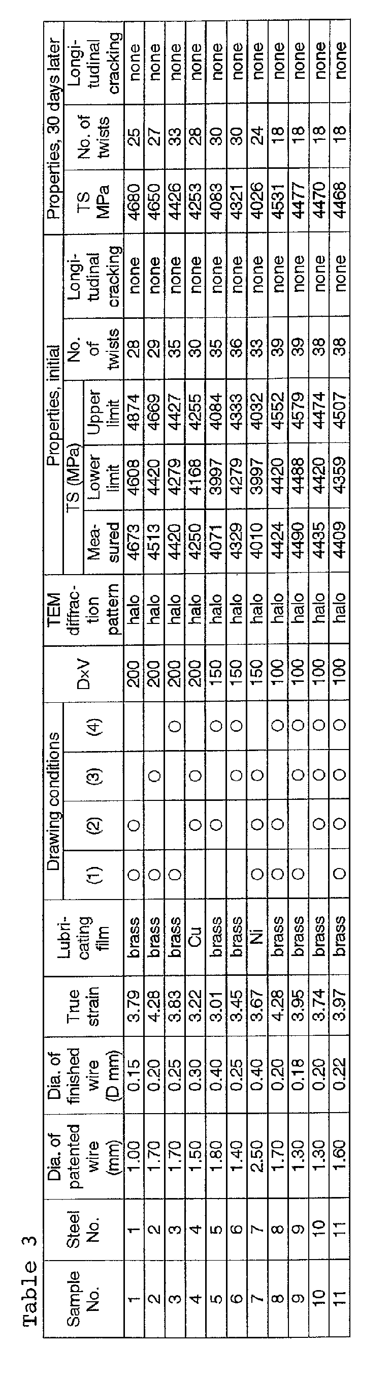
- Tables 3 and 4 also show the value of the product of V and D, where V is the drawing rate (m/min) in final drawing and D is the diameter.
- the wet drawing was carried out by using a cemented carbide die for pass to give a true strain ( ⁇ ) smaller than 3 or by using a diamond die for pass to give a true strain ( ⁇ ) larger than 3. Also, drawing for pass to give a true strain ( ⁇ ) larger than 3 was carried out under the following conditions (1) to (4) and (1') to (4').
- the conditions (1) to (4) meet the requirements of the present invention, and the conditions (1') to (4') are intended for comparison.
- the mark ⁇ in Tables 3 and 4 indicates that drawing was carried out under any of the conditions (1) to (4) and the blank indicates that drawing was carried out under any of the conditions (1') to (4').
- the finished steel wire which had undergone final drawing under the above-mentioned conditions, was examined for structure under a TEM. Whether the lamellar cementite in the pearlite structure is amorphous or not was judged from the diffraction pattern taken by projecting a beam (1.0 nm in radius) to the sample. (A halo pattern suggests the presence of an amorphous structure.)
- the finished steel wire was also tested for tensile strength (TS) and longitudinal cracking due to twisting. Twisting test was carried out in the following manner.
- a specimen (200 times the diameter in length) is taken from the finished steel wire immediately (5 hours) after final drawing. The specimen is twisted until longitudinal cracking occurs, and the number of twists is recorded. If the specimen remains intact after about 30 twists, the number of twists is recorded.
- the steel wire meeting the requirements of the present invention has tensile strength (in MPa) which varies with diameter (D mm) as shown in Fig. 2.
- the samples of steel wire in Inventive examples and Comparative Examples have tensile strength (defined as 3500 ⁇ D -0.145 MPa) which varies with carbon content (in mass%) as shown in Fig. 3.
- the steel wires designated at Sample Nos. 1 to 11 in Inventive examples which were prepared by the method specified in the present invention and have tensile strength within the range specified in the present invention, do not suffer longitudinal cracking after twisting more than 28 times. Also, they do not suffer longitudinal cracking after twisting more than 18 times in the case where they are aged for 30 days. Thus they proved to be excellent in resistance to strain aging embrittlement.
- the steel wires designated as Sample Nos. 29 to 36 which do not meet the requirements for the chemical composition and the rate of final drawing (greater than specified) and hence contain the lamellar cementite remaining in crystalline form, generally suffer longitudinal cracking immediately after drawing. All of them suffer longitudinal cracking after twisting only several times in the case where they are aged for 30 days.
- sample Nos. 37 to 39 suffer longitudinal cracking although they meet the requirements for the chemical composition.
- Sample No. 37 which has specified strength, does not suffer longitudinal cracking immediately after drawing but suffers longitudinal cracking after twisting ten times in the case where they are aged for 30 days. The reason for this is that strength after patenting is not enough and the drawing rate is excessively high, and hence the lamellar cementite remains in crystalline form.
- Samples Nos. 38 and 39 which have excessively low strength after patenting and also have lower-than-specified strength after drawing, do not suffer longitudinal cracking immediately after drawing but suffer longitudinal cracking after twisting 11 times or 16 times (respectively) in the case where they are aged for 30 days.
- the high-strength steel wire according to the present invention has a specific chemical composition, a specific diameter, a specific pearlite composition in which lamellar cementite is amorphous, and a specific tensile strength which is determined by diameter and carbon content. By virtue of these characteristic properties, it has good resistance to longitudinal cracking which usually occurs immediately after drawing or after aging. Despites its high strength, it also has good resistance to strain ageing embrittlement.
- the above-mentioned high-strength steel wire can be produced easily by the method according to the present invention.
Landscapes
- Chemical & Material Sciences (AREA)
- Engineering & Computer Science (AREA)
- Mechanical Engineering (AREA)
- Materials Engineering (AREA)
- Metallurgy (AREA)
- Organic Chemistry (AREA)
- Manufacturing & Machinery (AREA)
- Physics & Mathematics (AREA)
- Thermal Sciences (AREA)
- Crystallography & Structural Chemistry (AREA)
- Metal Extraction Processes (AREA)
- Heat Treatment Of Steel (AREA)
- Heat Treatment Of Strip Materials And Filament Materials (AREA)
Abstract
Description
Japanese Patent Publication No. 99746/1994 discloses a steel incorporated with Cr and Co which make the pearlite lamellar structure fine.
Japanese Patent Laid-open No. 99312/1997 discloses a method of drawing a steel wire continuously through a die in such a way that the reduction of area is controlled in response to the amount of strain due to drawing.
Japanese Patent Laid-open No. 121199/1998 discloses a steel wire composed mainly of fine pearlite, with its lamellar cementite rendered amorphous.
Japanese Patent Laid-open No. 199980/1999 discloses a steel wire having the pearlite structure such that ferrite contains no more than 1.5 atom% of carbon dissolved therein. Japanese Patent Laid-open No. 269607/1999 discloses a steel wire in which the amount of cementite is controlled in response to the amount of carbon and the average particle diameter of cementite is 2-10 nm.
- C :
- 0.75-1.20%
- Si :
- 0.1-1.5%
- Mn :
- 0.3-1.2%
- P :
- no more than 0.02%
- S :
- no more than 0.02%
- Al :
- no more than 0.005%
- N :
- no more than 0.008%
- (1) at least one of Ni : 0.10-1.0%, Cr : 0.10-1.0%, and Mo : 0.10-0.5%
- (2) Cu : no less than 0.05% and less than 0.20%
- (3) Co : no more than 2.0%
- (4) B : 0.0003-0.0050%
- C :
- 0.75-1.20%
- Si :
- 0.1-1.5%
- Mn :
- 0.3-1.2%
- P :
- no more than 0.02%
- S :
- no more than 0.02%
- Al :
- no more than 0.005%
- N :
- no more than 0.008%
- C :
- 0.75-1.20%
- Si :
- 0.1-1.5%
- Mn :
- 0.3-1.2%
- P :
- no more than 0.02%
- S :
- no more than 0.02%
- N :
- no more than 0.008%
- Al :
- no more than 0.005%
- Ni :
- 0.10-1.0%
- Cr :
- 0.10-1.0%
- Mo :
- 0.10-0.5%
- Cu :
- no less than 0.05% and less than 0.20%
- Co :
- no more than 2.0%
- B :
- 0.0003-0.0050%
- Drawing conditions according to the present invention:
- (1) The diamond die has an approach angle of 8 degrees.
- (2) The diamond die has a bearing length equal to 0.4d, where d is the inside diameter.
- (3) The wet drawing employs a liquid lubricant kept at 35±5°C.
- (4) Drawing through the diamond die is carried out such that the reduction of area is 18%.
- Drawing conditions for comparison:
- (1') The diamond die has an approach angle of 14 degrees.
- (2') The diamond die has a bearing length equal to 0.6d, where d is the inside diameter.
- (3') The wet drawing employs a liquid lubricant kept at 15±5°C.
- (4') Drawing through the diamond die is carried out such that the reduction of area is 22%.


Claims (6)
- A high-strength steel wire excellent in resistance to strain aging embrittlement and longitudinal cracking which is characterized by having a chemical composition (in mass%) including
- C :
- 0.75-1.20%
- Si :
- 0.1-1.5%
- Mn :
- 0.3-1.2%
- P :
- no more than 0.02%
- S :
- no more than 0.02%
- Al :
- no more than 0.005%
- N :
- no more than 0.008%
- A high-strength steel wire as defined in Claim 1, wherein the chemical composition further includes at least one of:
- N1 :
- 0.10-1.0%
- Cr :
- 0.10-1.0%
- Mo :
- 0.10-0.5%
- A high-strength steel wire as defined in Claim 1 or 2, wherein the chemical composition further includes Cu ; no less than 0.05% and no more than 0.20%.
- A high-strength steel wire as defined in any one of Claims 1 to 3, wherein the chemical composition further includes Co : no more than 2.0%.
- A high-strength steel wire as defined in any one of Claims 1 to 4, wherein the chemical composition further includes B : 0.0003-0.0050%.
- A method of producing a high-strength steel wire by drawing a hot-rolled wire rod, subjecting the drawn wire to patenting and acid pickling, forming thereon a metal lubricating film whose main phase is composed of at least one of Cu, N1, and Zn or an alloy thereof, and performing final drawing to reduce the diameter (D) to 0.15-0.4 mm, wherein the steel wire has the chemical composition specified in any one of Claims 1 to 5 above, the patenting treatment is carried out under the condition that the treated steel wire has a tensile strength no lower than (540 × [C] + 1055) MPa and no higher than (540 × [C] + 1065) MPa, where [C] denotes C content in %, and the final drawing is either cold wet drawing for a pass which results in a true strain (ε) in excess of 2.0 or drawing through a diamond die for a pass which results in a true strain (ε) in excess of 3.0, said drawing being so carried out as to satisfy at least two of the following four conditions:(1) the diamond die has an approach angle of 6-12 degrees;(2) the diamond die has a bearing section whose length is 0.3d to 0.5d, where d denotes its inside diameter;(3) the wet drawing employs a liquid lubricant which is kept at 35±10°C;(4) drawing through the diamond die is carried out such that the reduction of area is no more than 20%, and the final drawing is carried out at a drawing rate specified by DV which is no larger than 200 mnrm/min, where D denotes the diameter (in mm) of the steel wire and V denotes the drawing rate (in m/min).
Applications Claiming Priority (2)
| Application Number | Priority Date | Filing Date | Title |
|---|---|---|---|
| JP2001272905 | 2001-09-10 | ||
| JP2001272905A JP3954338B2 (en) | 2001-09-10 | 2001-09-10 | High-strength steel wire excellent in strain aging embrittlement resistance and longitudinal crack resistance and method for producing the same |
Publications (3)
| Publication Number | Publication Date |
|---|---|
| EP1293582A2 true EP1293582A2 (en) | 2003-03-19 |
| EP1293582A3 EP1293582A3 (en) | 2003-07-02 |
| EP1293582B1 EP1293582B1 (en) | 2004-11-24 |
Family
ID=19098197
Family Applications (1)
| Application Number | Title | Priority Date | Filing Date |
|---|---|---|---|
| EP02292034A Expired - Lifetime EP1293582B1 (en) | 2001-09-10 | 2002-08-13 | High-strength steel wire excelling in resistance to strain aging embrittlement and longitudinal cracking, and method for production thereof |
Country Status (5)
| Country | Link |
|---|---|
| US (1) | US6800147B2 (en) |
| EP (1) | EP1293582B1 (en) |
| JP (1) | JP3954338B2 (en) |
| KR (1) | KR100503545B1 (en) |
| CN (1) | CN1143903C (en) |
Cited By (3)
| Publication number | Priority date | Publication date | Assignee | Title |
|---|---|---|---|---|
| EP1433868A1 (en) * | 2002-12-18 | 2004-06-30 | The Goodyear Tire & Rubber Company | High strength, high carbon steel wire |
| EP1528115A1 (en) * | 2003-10-23 | 2005-05-04 | Kabushiki Kaisha Kobe Seiko Sho (Kobe Steel, Ltd.) | Very thin, high carbon steel wire and method of producing same |
| CN110918665A (en) * | 2019-12-18 | 2020-03-27 | 长沙新材料产业研究院有限公司 | High rare earth content aluminum alloy wire drawing die |
Families Citing this family (29)
| Publication number | Priority date | Publication date | Assignee | Title |
|---|---|---|---|---|
| JP4248790B2 (en) | 2002-02-06 | 2009-04-02 | 株式会社神戸製鋼所 | Steel wire rod excellent in mechanical descaling property and manufacturing method thereof |
| JP4088220B2 (en) * | 2002-09-26 | 2008-05-21 | 株式会社神戸製鋼所 | Hot-rolled wire rod with excellent wire drawing workability that can omit heat treatment before wire drawing |
| JP4788861B2 (en) * | 2003-11-28 | 2011-10-05 | ヤマハ株式会社 | Steel wire for musical instrument string and method for manufacturing the same |
| JP2005206853A (en) * | 2004-01-20 | 2005-08-04 | Kobe Steel Ltd | High carbon steel wire rod having excellent wire drawability, and production method therefor |
| JP4495668B2 (en) * | 2004-11-19 | 2010-07-07 | 株式会社神戸製鋼所 | High corrosion resistance steel |
| US7717976B2 (en) * | 2004-12-14 | 2010-05-18 | L&P Property Management Company | Method for making strain aging resistant steel |
| DE602005019268D1 (en) * | 2004-12-22 | 2010-03-25 | Kobe Steel Ltd | High carbon steel wire with excellent drawing properties and process for its production |
| EP1897964B8 (en) * | 2005-06-29 | 2019-07-17 | Nippon Steel Corporation | High-strength wire rod excelling in wire drawing performance and process for producing the same |
| JP5162875B2 (en) * | 2005-10-12 | 2013-03-13 | 新日鐵住金株式会社 | High strength wire rod excellent in wire drawing characteristics and method for producing the same |
| JP5108284B2 (en) * | 2005-12-14 | 2012-12-26 | 住友電工スチールワイヤー株式会社 | Steel wire for spring |
| JP2008069409A (en) | 2006-09-14 | 2008-03-27 | Bridgestone Corp | High strength high carbon steel wire and method for producing the same |
| KR101579338B1 (en) * | 2008-10-30 | 2015-12-21 | 가부시키가이샤 브리지스톤 | Carbon steel wire with high strength and excellent ductility and fatigue resistance, process for producing same, and method of evaluation |
| KR101470720B1 (en) | 2010-04-01 | 2014-12-08 | 가부시키가이샤 고베 세이코쇼 | High-carbon steel wire with excellent suitability for wiredrawing and fatigue property after wiredrawing |
| CN102847734B (en) * | 2011-06-28 | 2014-12-10 | 宝钢特钢有限公司 | Manufacturing method of 18CrNi8 coiled cold-drawn material for cold extrusion and its product |
| WO2013189082A1 (en) * | 2012-06-21 | 2013-12-27 | Nv Bekaert Sa | Sawing wire with bare steel surface and method to make the same |
| CN102861782B (en) * | 2012-10-31 | 2015-07-01 | 东莞市科力钢铁线材有限公司 | Manufacturing process of screw wire |
| KR101461724B1 (en) * | 2012-11-27 | 2014-11-14 | 주식회사 포스코 | High strength steel wire |
| CN104233097B (en) * | 2014-09-03 | 2017-02-15 | 马钢(集团)控股有限公司 | Hot-rolled wire rod for manufacturing high-strength steel strand of strong and smart grid and production method of hot-rolled wire rod |
| CN109072376B (en) * | 2016-03-28 | 2020-10-23 | 日本制铁株式会社 | Steel wire having excellent delayed fracture resistance |
| CN108489850B (en) * | 2018-02-28 | 2021-04-13 | 江苏省沙钢钢铁研究院有限公司 | Method for measuring stripping rate of oxide skin of wire rod |
| KR102326241B1 (en) * | 2019-12-20 | 2021-11-16 | 주식회사 포스코 | Ultra-high sterngth steel wire rod, steel wire and manufacturing method thereof for tire cord |
| CN111672918A (en) * | 2020-06-01 | 2020-09-18 | 江阴市利盟金属制品有限公司 | High-strength flexible shaft core drawing process for motor vehicle |
| CN114657471B (en) * | 2022-03-27 | 2022-12-23 | 中天钢铁集团有限公司 | A production method of low-carbon and energy-saving ≥ 2060MPa bridge cable wire rod |
| CN114951320B (en) * | 2022-05-07 | 2025-11-07 | 东南大学 | Production method of high-elongation high-strength high-carbon steel wire |
| CN115106391A (en) * | 2022-06-02 | 2022-09-27 | 镇江原轼新型材料有限公司 | Improved high-carbon steel diamond wire and preparation process thereof |
| CN115780557A (en) * | 2022-11-18 | 2023-03-14 | 江苏法尔胜研发中心有限公司 | Manufacturing method of ultrahigh-strength ACSR steel wire |
| CN116657062B (en) * | 2023-07-31 | 2023-10-10 | 江苏省沙钢钢铁研究院有限公司 | Wire rod for deep drawing and preparation method thereof |
| CN119144906B (en) * | 2024-11-19 | 2025-03-25 | 江苏省沙钢钢铁研究院有限公司 | 5200MPa grade steel wire, hot-rolled wire rod and production method of wire rod |
| KR20260090784A (en) * | 2024-12-09 | 2026-06-17 | 주식회사 포스코 | High strength and high ductility wire rod, steel wire and the method for manufacturing the same |
Family Cites Families (16)
| Publication number | Priority date | Publication date | Assignee | Title |
|---|---|---|---|---|
| JP2735647B2 (en) * | 1988-12-28 | 1998-04-02 | 新日本製鐵株式会社 | High strength and high ductility steel wire and method for producing high strength and high ductility extra fine steel wire |
| WO1992008817A1 (en) * | 1990-11-19 | 1992-05-29 | Nippon Steel Corporation | High-strength ultrafine steel wire with excellent workability in stranding, and process and apparatus for producing the same |
| DE69116843T2 (en) * | 1990-12-28 | 1996-08-14 | Kobe Steel Ltd | Tire cord made of steel wires with high strength and high toughness, and method of manufacturing the same |
| JPH0699746A (en) | 1992-09-21 | 1994-04-12 | Kurashiki Kako Co Ltd | Exhaust gas pipe supporting device |
| JP2500786B2 (en) * | 1992-11-16 | 1996-05-29 | 株式会社神戸製鋼所 | Hot rolled steel wire rod, extra fine steel wire and twisted steel wire, and method for producing extra fine steel wire |
| CN1043062C (en) * | 1994-03-28 | 1999-04-21 | 新日本制铁株式会社 | High-strength steel wire material of excellent fatigue characteristics and high-strength steel wire |
| JPH0999312A (en) | 1995-10-05 | 1997-04-15 | Nippon Steel Corp | Method for producing high-strength ultrafine steel wire with excellent ductility |
| US5776267A (en) * | 1995-10-27 | 1998-07-07 | Kabushiki Kaisha Kobe Seiko Sho | Spring steel with excellent resistance to hydrogen embrittlement and fatigue |
| JP3429155B2 (en) * | 1996-09-02 | 2003-07-22 | 株式会社神戸製鋼所 | High strength and high toughness steel wire and manufacturing method thereof |
| JP3429178B2 (en) | 1998-01-12 | 2003-07-22 | 株式会社神戸製鋼所 | Steel wire having excellent twisting characteristics, steel material for wire drawing, and method of manufacturing the same |
| JP3814070B2 (en) | 1998-01-20 | 2006-08-23 | 新日本製鐵株式会社 | High-strength ultrafine steel wire and method for producing the same |
| JP3277878B2 (en) | 1998-03-26 | 2002-04-22 | 住友金属工業株式会社 | Wire drawing reinforced high-strength steel wire and method of manufacturing the same |
| JP3409277B2 (en) * | 1998-05-13 | 2003-05-26 | 株式会社神戸製鋼所 | Rolled steel or bar steel for non-heat treated springs |
| JP2000063987A (en) | 1998-08-12 | 2000-02-29 | Sumitomo Metal Ind Ltd | High carbon steel wire with excellent drawability |
| KR100368530B1 (en) * | 1998-12-21 | 2003-01-24 | 가부시키가이샤 고베 세이코쇼 | Spring Steel Superior in Workability |
| JP3435112B2 (en) * | 1999-04-06 | 2003-08-11 | 株式会社神戸製鋼所 | High carbon steel wire excellent in longitudinal crack resistance, steel material for high carbon steel wire, and manufacturing method thereof |
-
2001
- 2001-09-10 JP JP2001272905A patent/JP3954338B2/en not_active Expired - Fee Related
-
2002
- 2002-08-13 EP EP02292034A patent/EP1293582B1/en not_active Expired - Lifetime
- 2002-08-23 US US10/226,137 patent/US6800147B2/en not_active Expired - Lifetime
- 2002-09-09 KR KR10-2002-0054286A patent/KR100503545B1/en not_active Expired - Fee Related
- 2002-09-10 CN CNB02141680XA patent/CN1143903C/en not_active Expired - Fee Related
Cited By (5)
| Publication number | Priority date | Publication date | Assignee | Title |
|---|---|---|---|---|
| EP1433868A1 (en) * | 2002-12-18 | 2004-06-30 | The Goodyear Tire & Rubber Company | High strength, high carbon steel wire |
| US6949149B2 (en) | 2002-12-18 | 2005-09-27 | The Goodyear Tire & Rubber Company | High strength, high carbon steel wire |
| EP1528115A1 (en) * | 2003-10-23 | 2005-05-04 | Kabushiki Kaisha Kobe Seiko Sho (Kobe Steel, Ltd.) | Very thin, high carbon steel wire and method of producing same |
| US7258756B2 (en) | 2003-10-23 | 2007-08-21 | Kobe Steel, Ltd. | Very thin, high carbon steel wire and method of producing same |
| CN110918665A (en) * | 2019-12-18 | 2020-03-27 | 长沙新材料产业研究院有限公司 | High rare earth content aluminum alloy wire drawing die |
Also Published As
| Publication number | Publication date |
|---|---|
| US20030066575A1 (en) | 2003-04-10 |
| US6800147B2 (en) | 2004-10-05 |
| KR20030022715A (en) | 2003-03-17 |
| CN1143903C (en) | 2004-03-31 |
| EP1293582B1 (en) | 2004-11-24 |
| JP3954338B2 (en) | 2007-08-08 |
| EP1293582A3 (en) | 2003-07-02 |
| JP2003082437A (en) | 2003-03-19 |
| CN1405350A (en) | 2003-03-26 |
| KR100503545B1 (en) | 2005-07-25 |
Similar Documents
| Publication | Publication Date | Title |
|---|---|---|
| EP1293582B1 (en) | High-strength steel wire excelling in resistance to strain aging embrittlement and longitudinal cracking, and method for production thereof | |
| US6322641B1 (en) | High-carbon steel wire superior in resistance to longitudinal cracking, steel product for the same, and process for production of the same | |
| JP3997867B2 (en) | Steel wire, method for producing the same, and method for producing steel wire using the steel wire | |
| EP1900837B1 (en) | High-strength wire rod excelling in wire drawing performance and high strength steel wire | |
| KR100651302B1 (en) | High carbon steel wire rod superior in wire-drawability and method for producing the same | |
| KR100194431B1 (en) | Excellent high strength steel wire and high strength steel wire with fatigue characteristics | |
| EP2025769A1 (en) | High-ductility high-carbon steel wire | |
| US6645319B2 (en) | Wire rod for drawing superior in twisting characteristics and method for production thereof | |
| EP3988678B1 (en) | Wire rod | |
| MX2013001724A (en) | Special steel steel-wire and special steel wire material. | |
| CN101331243A (en) | High-strength wire rod excellent in drawing properties and manufacturing method thereof | |
| EP0632138A1 (en) | High toughness and high strength untempered steel and processing method thereof | |
| CA2980886C (en) | High-carbon steel wire material with excellent wire drawability, and steel wire | |
| JP2000073137A (en) | Steel wire with excellent cold workability | |
| KR20010042224A (en) | Wire for high-fatigue-strength steel wire, steel wire and production method therefor | |
| JP4267375B2 (en) | Wire material for high-strength steel wire, high-strength steel wire, and production method thereof | |
| JP2000345294A (en) | Steel wire, extra fine steel wire and twisted steel wire | |
| JP2004011002A (en) | Wire and wire for wire drawing | |
| JP3428502B2 (en) | Steel wire, extra fine steel wire and twisted steel wire | |
| JP2000337334A (en) | High-strength bolt with excellent delayed fracture resistance | |
| JPH07179994A (en) | High strength and high ductility hypereutectoid steel wire and its manufacturing method | |
| JP2000178685A (en) | Steel wire rod excellent in fatigue characteristics and drawability and method for producing the same | |
| KR100276298B1 (en) | Manufacturing method of hard steel wire for drawing high manganese | |
| JPH08295931A (en) | Wire rod with excellent wire drawing workability | |
| JP3292504B2 (en) | High carbon steel wire with good workability |
Legal Events
| Date | Code | Title | Description |
|---|---|---|---|
| PUAI | Public reference made under article 153(3) epc to a published international application that has entered the european phase |
Free format text: ORIGINAL CODE: 0009012 |
|
| AK | Designated contracting states |
Kind code of ref document: A2 Designated state(s): AT BE BG CH CY CZ DE DK EE ES FI FR GB GR IE IT LI LU MC NL PT SE SK TR |
|
| AX | Request for extension of the european patent |
Extension state: AL LT LV MK RO SI |
|
| PUAL | Search report despatched |
Free format text: ORIGINAL CODE: 0009013 |
|
| AK | Designated contracting states |
Designated state(s): AT BE BG CH CY CZ DE DK EE ES FI FR GB GR IE IT LI LU MC NL PT SE SK TR |
|
| AX | Request for extension of the european patent |
Extension state: AL LT LV MK RO SI |
|
| 17P | Request for examination filed |
Effective date: 20030804 |
|
| AKX | Designation fees paid |
Designated state(s): BE FR IT |
|
| REG | Reference to a national code |
Ref country code: DE Ref legal event code: 8566 |
|
| GRAP | Despatch of communication of intention to grant a patent |
Free format text: ORIGINAL CODE: EPIDOSNIGR1 |
|
| GRAS | Grant fee paid |
Free format text: ORIGINAL CODE: EPIDOSNIGR3 |
|
| GRAA | (expected) grant |
Free format text: ORIGINAL CODE: 0009210 |
|
| AK | Designated contracting states |
Kind code of ref document: B1 Designated state(s): BE FR IT |
|
| ET | Fr: translation filed | ||
| PLBE | No opposition filed within time limit |
Free format text: ORIGINAL CODE: 0009261 |
|
| STAA | Information on the status of an ep patent application or granted ep patent |
Free format text: STATUS: NO OPPOSITION FILED WITHIN TIME LIMIT |
|
| 26N | No opposition filed |
Effective date: 20050825 |
|
| REG | Reference to a national code |
Ref country code: FR Ref legal event code: PLFP Year of fee payment: 15 |
|
| REG | Reference to a national code |
Ref country code: FR Ref legal event code: PLFP Year of fee payment: 16 |
|
| REG | Reference to a national code |
Ref country code: FR Ref legal event code: PLFP Year of fee payment: 17 |
|
| PGFP | Annual fee paid to national office [announced via postgrant information from national office to epo] |
Ref country code: FR Payment date: 20200715 Year of fee payment: 19 |
|
| PGFP | Annual fee paid to national office [announced via postgrant information from national office to epo] |
Ref country code: BE Payment date: 20200715 Year of fee payment: 19 Ref country code: IT Payment date: 20200713 Year of fee payment: 19 |
|
| REG | Reference to a national code |
Ref country code: BE Ref legal event code: MM Effective date: 20210831 |
|
| PG25 | Lapsed in a contracting state [announced via postgrant information from national office to epo] |
Ref country code: IT Free format text: LAPSE BECAUSE OF NON-PAYMENT OF DUE FEES Effective date: 20210813 Ref country code: FR Free format text: LAPSE BECAUSE OF NON-PAYMENT OF DUE FEES Effective date: 20210831 Ref country code: BE Free format text: LAPSE BECAUSE OF NON-PAYMENT OF DUE FEES Effective date: 20210831 |