JP2004011002A - Element wire for drawing and wire - Google Patents
Element wire for drawing and wire Download PDFInfo
- Publication number
- JP2004011002A JP2004011002A JP2002168979A JP2002168979A JP2004011002A JP 2004011002 A JP2004011002 A JP 2004011002A JP 2002168979 A JP2002168979 A JP 2002168979A JP 2002168979 A JP2002168979 A JP 2002168979A JP 2004011002 A JP2004011002 A JP 2004011002A
- Authority
- JP
- Japan
- Prior art keywords
- wire
- less
- steel
- diameter
- tensile strength
- Prior art date
- Legal status (The legal status is an assumption and is not a legal conclusion. Google has not performed a legal analysis and makes no representation as to the accuracy of the status listed.)
- Pending
Links
Images

Landscapes
- Heat Treatment Of Strip Materials And Filament Materials (AREA)
- Heat Treatment Of Steel (AREA)
Abstract
Description
【0001】
【発明の属する技術分野】
本発明は、伸線加工用の素線及び線に関する。より詳しくは、例えば、自動車のラジアルタイヤや、各種産業用ベルトやホースの補強材として用いられるスチールコード、更には、ソーイングワイヤなどの用途に好適な伸線加工用の鋼素線及び前記の鋼素線を伸線加工した鋼線に関する。
【0002】
【従来の技術】
自動車のラジアルタイヤや、各種のベルト、ホースの補強材として使用されるスチールコード、或いは、ソーイングワイヤには、一般に、熱間圧延した直径が5〜6mmの線材に数回のパテンティング処理と伸線加工とを施し、更に、その後最終パテンティング処理を行って微細なパーライト組織とした線を素材(素線)として、これに最終の伸線加工を施した線が用いられている。
【0003】
しかし、従来の製造法において、パーライト組織を得るためのパテンティング処理は、鉛浴や流動層を用いる熱処理であるため次のような問題がある。
【0004】
すなわち、鉛浴は環境面に対する配慮からその使用を控える動きが大きくなっている。又、流動層は鉛浴に比べて熱伝達係数が小さいため、冷却速度が遅くなって工業的規模では被処理材の特性にバラツキが生じやすい。特に、直径が1.0mmを大きく下回る極細線を流動層でパテンティング処理して、引張強さなどの機械的性質を安定させることは極めて難しい。更に、流動層の設置には設備コストが嵩むので、製品コストの上昇が避けられない。
【0005】
一方では、近年、製品の軽量化や歩留まり向上など種々の目的から、スチールコードやソーイングワイヤの高強度化が要求されるようになり、鋼中のC含有量を高めることや、最終伸線工程での加工量を高めることが行われ、ある程度の高強度化が達成されている。しかし、上記鋼中のC含有量の上昇や、最終伸線工程での加工量の上昇は伸線加工性の低下を招くため、伸線加工中に断線が生じ、生産性と歩留りの大きな低下をきたす。
【0006】
上記の問題に対して、特許第2627373号公報には、線径0.01〜0.50mmの極細金属線であって、鋼の組織が炭素含有量0.60〜1.20重量%である鋼線を焼入れ、焼戻しして得られる焼戻しマルテンサイト組織で、引張強さが300kgf/mm2以上である「高強度極細金属線」が開示されている。しかし、この公報で提案された技術の場合、その実施例における記載からも明らかなように、線径(直径)が0.10mm未満の極細線の場合には430kgf/mm2(4220MPa)の引張強さが得られているものの、例えば、自動車のラジアルタイヤのスチールコード用として用いられ、しかも、対象量が多い線径が0.15〜0.40mmの鋼線の場合には、引張強さは高々365kgf/mm2(3580MPa)でしかない。この引張強さは、従来型の、パテンティング処理後に最終伸線加工して実用化されている線が有する3600MPaクラスという引張強さに比べて劣るものである。
【0007】
【発明が解決しようとする課題】
本発明は、上記現状に鑑みてなされたもので、その目的は、環境面での問題がなく、しかも、工業的な高い生産性の下に安定して廉価に製造でき、スチールコードやソーイングワイヤなどの用途に好適な、直径が2.5mm以下で引張強さが1600MPa以上、絞りが30%以上の伸線加工用の素線を提供することである。本発明のもう1つの目的は、前記の素線を素材とし、特に、直径が0.15〜0.40mmで引張強さが3600MPa以上の線を提供することである。本発明の更にもう1つの目的は、前記の素線を素材とし、特に、直径が0.02〜0.10mmで引張強さが4500MPa以上の線を提供することである。
【0008】
【課題を解決するための手段】
本発明の要旨は、下記(1)〜(4)に示す伸線加工用の素線、並びに、(5)及び(6)に示す線にある。
【0009】
(1)質量%で、C:0.5〜0.9%、Si:0.1〜1.5%、Cr:0.1〜1.5%で、且つSi+Cr:0.5〜2.0%、Mn:0.1〜1.0%を含み、残部がFe及び不純物からなり、不純物中のTiは0.003%以下、Nは0.010%以下、Pは0.02%以下、Sは0.015%以下、O(酸素)は0.0020%以下で、組織の70%以上が焼戻しマルテンサイト組織であり、引張強さが1600MPa以上、絞りが30%以上である直径が2.5mm以下の伸線加工用の素線。
【0010】
(2)質量%で、C:0.5〜0.9%、Si:0.1〜1.5%、Cr:0.1〜1.5%で、且つSi+Cr:0.5〜2.0%、Mn:0.1〜1.0%を含み、更に、Mo:0.1〜1.0%、W:0.1〜1.0%、V:0.05〜0.30%及びCu:0.1〜2.0%から選択される1種以上を含有し、残部がFe及び不純物からなり、不純物中のTiは0.003%以下、Nは0.010%以下、Pは0.02%以下、Sは0.015%以下、O(酸素)は0.0020%以下で、組織の70%以上が焼戻しマルテンサイト組織であり、引張強さが1600MPa以上、絞りが30%以上である直径が2.5mm以下の伸線加工用の素線。
【0011】
(3)質量%で、C:0.5〜0.9%、Si:0.1〜1.5%、Cr:0.1〜1.5%で、且つSi+Cr:0.5〜2.0%、Mn:0.1〜1.0%を含み、更に、Nb:0.005〜0.03%、B:0.0003〜0.005%及びAl:0.005〜0.030%から選択される1種以上を含有し、残部がFe及び不純物からなり、不純物中のTiは0.003%以下、Nは0.010%以下、Pは0.02%以下、Sは0.015%以下、O(酸素)は0.0020%以下で、組織の70%以上が焼戻しマルテンサイト組織であり、引張強さが1600MPa以上、絞りが30%以上である直径が2.5mm以下の伸線加工用の素線。
【0012】
(4)質量%で、C:0.5〜0.9%、Si:0.1〜1.5%、Cr:0.1〜1.5%で、且つSi+Cr:0.5〜2.0%、Mn:0.1〜1.0%を含み、更に、Mo:0.1〜1.0%、W:0.1〜1.0%、V:0.05〜0.30%及びCu:0.1〜2.0%から選択される1種以上、並びに、Nb:0.005〜0.03%、B:0.0003〜0.005%及びAl:0.005〜0.030%から選択される1種以上を含有し、残部がFe及び不純物からなり、不純物中のTiは0.003%以下、Nは0.010%以下、Pは0.02%以下、Sは0.015%以下、O(酸素)は0.0020%以下で、組織の70%以上が焼戻しマルテンサイト組織であり、引張強さが1600MPa以上、絞りが30%以上である直径が2.5mm以下の伸線加工用の素線。
【0013】
(5)上記(1)から(4)までのいずれかに記載の伸線加工用の素線を用いて、直径が0.15〜0.40mmに伸線した引張強さが3600MPa以上の線。
【0014】
(6)上記(1)から(4)までのいずれかに記載の伸線加工用の素線を用いて、直径が0.02〜0.10mmに伸線した引張強さが4500MPa以上の線。
【0015】
なお、本発明における「焼戻しマルテンサイト組織」とは、オーステナイト相を冷却(急冷)することによってマルテンサイト変態させた相(つまりマルテンサイト)が、Ac1点以下の温度に加熱されて焼戻しされた、炭化物が析出している組織を指す。
【0016】
ここで、或る相の体積割合は、顕微鏡組織から評価される面積割合に等しいことが知られており、したがって、上記焼戻しマルテンサイトが組織に占める割合は、例えば次の方法によって、焼入れしたままの組織に占めるマルテンサイト組織の割合から決定すればよい。
【0017】
先ず、焼入れしたままの組織を鏡面研磨した後、光学顕微鏡で観察する。具体的には、例えば、倍率を200倍として任意の4視野について写真を撮影し、その写真中でマルテンサイト組織が占める割合を通常の画像処理法などによって計測する。なお、化学組成が本発明で規定する含有量の範囲内にある鋼を急冷して焼入れすると、マルテンサイト組織以外に、オーステナイトが未変態で残った残留オーステナイトと称される組織も存在するが、光学顕微鏡による観察では、残留オーステナイト組織とマルテンサイト組織とを区別することは難しい。
【0018】
そこで、急冷して焼入れした鋼の光学顕微鏡による観察から、組織中にフェライトやパーライトが占める割合を求め、その残りを「見かけ上のマルテンサイト組織」、つまり、マルテンサイト組織と残留オーステナイト組織とが占める割合(α%)とする。
【0019】
次に、X線回折による通常の方法で焼入れしたままの組織に占める残留オーステナイト組織の割合(β%)を求める。
【0020】
最後に、下記▲1▼式から、焼入れしたままの組織に占めるマルテンサイト組織の割合(X%)を計算する。ここで、焼入れしたままのマルテンサイト組織は、Ac1点以下の温度に加熱されて焼戻し処理され、焼戻しマルテンサイト組織になる。つまり、焼入れしたままの組織に占めるマルテンサイト組織の割合と焼戻し後の組織に占める焼戻しマルテンサイト組織の割合とは等しく、▲1▼式から求めた焼入れしたままの組織に占めるマルテンサイト組織の割合が焼戻し後の組織に占める焼戻しマルテンサイト組織の割合そのものとなる。
【0021】
X=α−{(α×β)/100}・・・▲1▼。
【0022】
以下、上記の(1)〜(6)の伸線加工用の素線又は線に係る発明をそれぞれ(1)〜(6)の発明という。
【0023】
本発明者らは、伸線加工性に優れ、スチールコードやソーイングワイヤなどの用途に好適な伸線加工用の素線を得るとともに、前記の素線を素材とする高強度の細線や極細線を得るために、調査・研究を重ねた。その結果、下記の知見を得た。
【0024】
(a)適正な条件での焼入れと焼戻しの処理を受け、組織の70%以上がマルテンサイト組織(つまり、焼戻しマルテンサイト組織)となる高炭素鋼の素線は、組織がパーライト組織やベイナイト組織の高炭素鋼の素線に比べて、高い引張強さを有し、且つ、30%以上の絞りを有する。
【0025】
(b)上記各組織の高炭素鋼の素線を同じ加工量で伸線加工を行った場合、組織の70%以上が焼戻しマルテンサイト組織である場合の引張強さがパーライト組織やベイナイト組織の場合の引張強さよりも大きい。
【0026】
(c)焼戻しマルテンサイト組織が組織の70%以上を占める高炭素鋼の素線の引張強さ、及びこの素線を伸線加工した高炭素鋼線の引張強さを高めるためには、セメンタイトを微細析出させるのが最も有効であり、そのためには鋼にSiとCrを積極的に含有させればよい。
【0027】
(d)Si及びCrを積極的に含有させた高炭素鋼の素線において、組織の70%以上が焼戻しマルテンサイト組織である場合の引張強さが、組織がパーライトである場合の引張強さを大幅に上回るようにするには、焼戻し温度を375〜450℃にすればよい。
【0028】
(e)前記焼戻しマルテンサイト組織が組織の70%以上を占める高炭素鋼の素線にメッキ処理を施す際に、被処理材である高炭素鋼の素線の温度が450℃を上回る場合には、二次析出するMo、W、V及びCuのうちの1種以上を含有させて引張強さの低下を抑止すればよい。なお、この場合には、メッキ処理時の熱処理で焼戻しできるので、焼入れ処理後に焼戻しを行うことなく直接メッキ処理してもよい。
【0029】
本発明は、上記の知見に基づいて完成されたものである。
【0030】
【発明の実施の形態】
以下、本発明の各要件について詳しく説明する。なお、各元素の含有量の「%」表示は「質量%」を意味する。
【0031】
(A)化学組成
本発明においては、伸線加工性の確保、最終製品における特性の付与及び工業的な生産性の確保のために、素線及び線の化学組成を下記の範囲に限定する。
【0032】
C:0.5〜0.9%
Cは、線の強度を高めるのに有効な元素である。その含有量が0.5%未満の場合には、自動車ラジアルタイヤ用のスチールコードの一般的な製造法である真歪み量が3.6の伸線加工、例えば、直径1.2mmから0.2mmへの伸線加工では、最終伸線後に引張強さが3600MPaに達しない。一方、Cの含有量が多すぎると、焼入れした際に焼割れが発生し、伸線加工が困難になる。特に、Cの含有量が0.9%を超えると、焼割れの発生が顕著になり、伸線加工できなくなる。したがって、C含有量を0.5〜0.9%とした。
【0033】
なお、真歪(ε)は伸線加工前の線材又は線の直径(d0)と伸線加工後の線の直径(d)を用いて、ε=2loge(d0/d)の式で表される。
【0034】
Si:0.1〜1.5%
Siは、セメンタイトを微細に分散させる作用が大きく、特に、後述するCrと複合して含有させることで、焼戻し後の強度を大きく高める作用を有する。又、Siは脱酸剤として必要な元素でもある。脱酸剤としての効果を十分発揮させるためには、Siを0.1%以上含有させる必要がある。一方、Siの含有量が1.5%を超えると、焼戻しにおけるセメンタイトの析出が著しく遅延し、工業的な生産性の低下を招く。したがって、Siの含有量を0.1〜1.5%とした。
【0035】
Cr:0.1〜1.5%
Crは、セメンタイトを微細に分散させる作用が大きく、特に、上述のSiと複合して含有させることで、焼戻し後の強度を大きく高める作用を有する。しかし、その含有量が0.1%未満では添加効果に乏しく、一方、1.5%を超えると焼戻しにおけるセメンタイトの析出が著しく遅くなり、工業的な生産性の低下をきたす。したがって、Crの含有量を0.1〜1.5%とした。
【0036】
Si+Cr:0.5〜2.0%
上述のように、Si及びCrは、セメンタイトを微細に分散させる作用が大きく、特に、両元素を複合して含有させることで、焼戻し後の強度を大幅に高めることができる。しかし、その含有量の和であるSi+Crの値が0.5%未満の場合には、上記効果が得難い。一方、Si+Crの値が2.0%を超えると焼戻しにおけるセメンタイトの析出が著しく遅延するので、工業的な生産性の低下を招く。したがって、SiとCrの含有量の和であるSi+Crの値を0.5〜2.0%とした。
【0037】
Mn:0.1〜1.0%
Mnは、強度を高める作用に加えて、鋼中のSをMnSとして固定して熱間脆性を防止する作用を有する。しかし、その含有量が0.1%未満では前記の効果が得難い。一方、1.0%を超えて含有させても前記の効果は飽和し、コストが嵩むばかりである。したがって、Mnの含有量を0.1〜1.0%とした。
【0038】
本発明においては、伸線加工性を確保する観点から、不純物元素としてのTi、N、P、S及びO(酸素)の含有量を下記のように制限する。
【0039】
Ti:0.003%以下
Tiは、Nと結合して鋼中でTiNを形成する。このTiNは伸線加工中の断線の起点になりやすい。特に、Tiの含有量が0.003%を超えると、TiNが粗大化して伸線加工中に断線が多発する。したがって、Ti含有量を0.003%以下とした。
【0040】
N:0.010%以下
Nは冷間での伸線加工中に転位に固着して線の強度を上昇させる反面で、伸線加工性を低下させてしまう。特に、その含有量が0.010%を超えると、伸線加工性の低下が著しくなる。したがって、Nの含有量を0.010%以下とした。
【0041】
P:0.02%以下
Pは粒界に偏析しやすく線を脆化させるため、伸線加工性を低下させてしまう。特に、その含有量が0.02%を超えると、伸線加工性の低下が著しくなる。したがって、Pの含有量を0.02%以下とした。
【0042】
S:0.015%以下
Sは、Mnと結合して鋼中でMnSを形成する。このMnSは伸線加工中の断線の起点となりやすい。特に、Sの含有量が0.015%を超えるとMnSが多量に生成するため伸線加工性の低下が著しくなる。したがって、Sの含有量を0.015%以下とした。
【0043】
O(酸素):0.0020%以下
Oは鋼中でAl、Siなどと結合して酸化物系介在物を形成し、伸線加工性を低下させてしまう。特に、Oの含有量が0.0020%を超えると、酸化物系介在物が粗大化するので伸線加工性の低下が著しくなって、伸線加工中に断線が多発する。したがって、Oの含有量を0.0020%以下とした。
【0044】
本発明に係る素線が含有するFe以外の成分元素は、(1)の発明のように上記のCからO(酸素)までの元素だけであってもよい。しかし、上記の成分に加え、必要に応じて、Mo、W、V及びCuから選択される1種以上、又は/及びNb、B及びAlから選択される1種以上を選択的に含有させることができる。すなわち、Mo、W、V、Cu、Nb、B及びAlの各元素を任意添加元素として添加し、含有させてもよい。
【0045】
以下、上記の任意添加元素に関して説明する。
【0046】
先ず、添加すれば、いずれも強度を高める作用を有するMo、W、V及びCuについて説明する。
【0047】
Mo:0.1〜1.0%
Moは、添加すれば、焼戻し中に炭化物として微細に析出して強度を高める作用を有する。この効果を確実に得るには、Moは0.1%以上の含有量とすることが好ましい。しかし、1.0%を超えて含有させても前記の効果は飽和し、コストが嵩むばかりである。したがって、Moを添加する場合には、その含有量を0.1〜1.0%とするのがよい。
【0048】
W:0.1〜1.0%
Wは、添加すれば、焼戻し中に炭化物として微細に析出して強度を高める作用を有する。この効果を確実に得るには、Wは0.1%以上の含有量とすることが好ましい。しかし、1.0%を超えて含有させても前記の効果は飽和し、コストが嵩むばかりである。したがって、Wを添加する場合には、その含有量を0.1〜1.0%とするのがよい。
【0049】
V:0.05〜0.30%
Vは、添加すれば、焼戻し中に炭化物や窒化物として微細に析出して強度を高める作用を有する。この効果を確実に得るには、Vは0.05%以上の含有量とすることが好ましい。しかし、その含有量が0.30%を超えると、焼入れのためにオーステナイト域に加熱しても粗大な炭化物や窒化物が残存するので、伸線加工時に断線が多発する。したがって、Vを添加する場合には、その含有量を0.05〜0.30%とするのがよい。
【0050】
Cu:0.1〜2.0%
Cuは、添加すれば、焼戻し中に微細に析出して強度を高める作用を有する。この効果を確実に得るには、Cuは0.1%以上の含有量とすることが好ましい。しかし、その含有量が2.0%を超えると、結晶粒界に偏析して鋼塊の分塊圧延や線材の熱間圧延など熱間加工時における割れや疵の発生が顕著になる。したがって、Cuを添加する場合には、その含有量を0.1〜2.0%とするのがよい。
【0051】
(1)の発明に係る素線の化学組成中のFeの一部に代えて、上記のMo、W、V及びCuのいずれか1種以上を複合して含有させることによって、(2)の発明に係る素線の化学組成が得られる。
【0052】
次に、添加すれば、いずれも伸線加工性を高める作用を有するNb、B及びAlについて説明する。
【0053】
Nb:0.005〜0.03%
Nbは、添加すれば、オーステナイト結晶粒を微細にして、伸線加工性を高める作用を有する。この効果を確実に得るには、Nbは0.005%以上の含有量とすることが望ましい。しかし、その含有量が0.03%を超えると、焼入れのためにオーステナイト域に加熱しても粗大な炭化物や窒化物が残存するので、伸線加工時に断線が多発する。したがって、Nbを添加する場合には、その含有量を0.005〜0.03%とするのがよい。
【0054】
B:0.0003〜0.005%
Bは、添加すれば、Nと結合してBNを形成することで固溶Nを低減し、伸線加工性を高める作用を有する。この効果を確実に得るには、Bは0.0003%以上の含有量とすることが好ましい。しかし、その含有量が0.005%を超えると、粗大なBNが生成して、伸線加工中に断線が多発する。したがって、Bを添加する場合には、その含有量を0.0003〜0.005%とするのがよい。
【0055】
Al:0.005〜0.030%
Alは、添加すれば、Nと結合してAlNを形成し、オーステナイト結晶粒を微細化するとともに固溶Nを低減し、伸線加工性を高める作用を有する。この効果を確実に得るには、Alは0.005%以上の含有量とすることが好ましい。しかし、Alを0.030%を超えて含有させると、Al2O3を主成分とする酸化物系介在物が粗大化して、伸線加工中に断線が多発する。したがって、Alを添加する場合には、その含有量を0.005〜0.030%とするのがよい。
【0056】
(1)の発明に係る素線の化学組成中のFeの一部に代えて、上記のNb、B及びAlのいずれか1種以上を複合して含有させることによって、(3)の発明に係る素線の化学組成が得られる。
【0057】
又、(1)の発明に係る素線の化学組成中のFeの一部に代えて、前記のMo、W、V及びCuのいずれか1種以上、並びに、上記のNb、B及びAlのいずれか1種以上を複合して含有させることによって、(4)の発明に係る素線の化学組成が得られる。
【0058】
(B)ミクロ組織
高炭素鋼のミクロ組織には、パーライト組織、ベイナイト組織やマルテンサイト組織などがある。
【0059】
本発明者らは、表1に示す鋼Cを用いて、異なるミクロ組織を有する直径が1.2mmで長さが1000mmの試験材を作製した。
【0060】
【表1】

すなわち、伸線加工して得た直径が1.2mmの線から長さが1000mmの試験材を採取し、条件を変えて熱処理した後、通常の方法で直径0.20mmまで伸線加工した。表2に、熱処理した直径1.2mmの線(素線)のミクロ組織と引張特性、及び直径0.20mmの伸線材の引張特性を示す。ここで、表2における熱処理条件1〜8は次に示すとおりである。
【0062】
条件1:920℃に加熱して20秒保持した後、580℃の鉛浴中に浸漬して20秒保持し、保持後は大気中で放冷。
【0063】
条件2:920℃に加熱して20秒保持した後、500℃の鉛浴中に浸漬して60秒保持し、保持後は大気中で放冷。
【0064】
条件3:860℃に加熱して60秒保持した後で油焼入れし、次いで350℃で3分焼戻し処理してから大気中で放冷。
【0065】
条件4:860℃に加熱して60秒保持した後で油焼入れし、次いで375℃で3分焼戻し処理してから大気中で放冷。
【0066】
条件5:1150℃に加熱して60秒保持した後で油焼入れし、次いで375℃で3分焼戻し処理してから大気中で放冷。
【0067】
条件6:860℃に加熱して60秒保持した後で油焼入れし、次いで400℃で3分焼戻し処理してから大気中で放冷。
【0068】
条件7:860℃に加熱して60秒保持した後で油焼入れし、次いで450℃で3分焼戻し処理してから大気中で放冷。
【0069】
条件8:860℃に加熱して60秒保持した後で油焼入れし、次いで600℃で3分焼戻し処理してから大気中で放冷。
【0070】
なお、条件1及び条件3で熱処理したものは、断線が多発して0.20mmにまで伸線加工できず、引張試験を行わなかった。
【0071】
【表2】
表2から、素線の組織が適正な条件での焼入れと焼戻しの処理を受けたマルテンサイト組織(つまり、焼戻しマルテンサイト組織で、表2の場合の条件4、条件6及び条件7の熱処理を受けたもの)の場合の引張強さは、素線の組織がパーライト組織やベイナイト組織の場合の引張強さよりも大きい。これらの素線を同じ加工量で伸線加工した線の引張強さに関しても同様なことがいえる。
【0073】
なお、既に述べたように、本発明における「焼戻しマルテンサイト組織」とは、オーステナイト相を冷却(急冷)することによってマルテンサイト変態させた相(つまりマルテンサイト)が、Ac1点以下の温度に加熱されて焼戻しされた、炭化物が析出している組織を指す。
【0074】
表2中の熱処理条件3〜8において、焼戻しマルテンサイトが組織に占める割合は、次のようにして求めた。
【0075】
すなわち、先ず、焼入れしたままの組織を鏡面研磨した後、倍率を200倍として任意の4視野について観察した。その結果、熱処理条件3〜8のいずれの場合も、焼入れままの組織が前記した「見かけ上のマルテンサイト組織」(つまり、マルテンサイトと残留オーステナイトの混合組織)だけからなり「α=100%」であることがわかった。次に、X線回折による通常の方法で、焼入れしたままの組織に占める残留オーステナイト組織の割合を求めた。その結果、熱処理条件3〜8のいずれの場合も「β=10%」であることがわかった。
【0076】
既に述べたように、焼入れしたままの組織に占めるマルテンサイト組織の割合と焼戻し後の組織に占める焼戻しマルテンサイト組織の割合とは等しい。そこで最後に、前記▲1▼式を用いて焼戻しマルテンサイト組織の割合(X%)を算出し、熱処理条件3〜8のいずれの場合にも「X=90%」であることを得た。
【0077】
なお、上述の組織に占める焼戻しマルテンサイト組織の割合の導出方法から明らかなとおり、表2中の熱処理条件3〜8における焼戻しマルテンサイト以外の各10%の組織は、いずれも残留オーステナイトが焼戻し処理を受けて分解した組織である。
【0078】
焼戻しマルテンサイト組織は、一般的な加熱炉を用いて鋼をオーステナイト域に加熱した後、油や水などの適当な冷却媒体を用いて急冷し、その後、一般的な熱処理炉を用いて焼戻し処理することで得られるため、パーライト組織のようにパテンティングのための鉛浴や流動層を用いる必要がない。しかも、焼戻しマルテンサイト組織からなる素線には、安定した高強度と良好な伸線加工性が確保できる。ここで、素線の組織中に焼戻しマルテンサイトの占める割合が70%以上に達すると、その素線の特性はほとんど焼戻しマルテンサイトの特性に支配されるようになる。したがって、本発明に係る素線の組織の70%以上を焼戻しマルテンサイト組織と規定した。ここで、焼戻しマルテンサイト組織の割合は70%以上でありさえすればよく、その上限値は化学組成、及び熱処理条件に応じて得られる最大量のマルテンサイト率であってもよい。なお、焼戻しマルテンサイト以外の組織は規定する必要はなく、残留オーステナイト、フェライト、ベイナイトやパーライトが焼戻し処理を受けた組織であってよい。
【0079】
素線の組織を焼戻しマルテンサイト組織とするためには、例えば、鋼組成に応じて850〜950℃のオーステナイト域に加熱してから、油や水などの適当な冷却媒体を用いて急冷し、その後、鋼組成に応じて、375〜600℃で焼戻し処理すればよい。例えば、鋼組成が(1)及び(3)の発明に係る化学組成の場合には、375〜450℃で焼戻し処理すればよいし、鋼組成が(2)及び(4)の発明に係る化学組成の場合には、450〜600℃で焼戻し処理すればよい。
【0080】
(C)素線の引張特性と直径
素線の引張強さが高ければ高いほど、伸線加工時の加工量を低減できるため、工業的に有利である。
【0081】
素線の引張強さが1600MPa未満の場合には、自動車ラジアルタイヤ用のスチールコードの一般的な製造法である真歪み量が3.6の伸線加工、例えば、直径1.2mmから0.2mmへの伸線加工では、引張強さが3600MPaに達しない。したがって、素線の引張強さを1600MPa以上と規定した。伸線加工後の引張強さを更に高めたい場合、或いは伸線加工時の加工量を低減したい場合には、素線の引張強さを1800MPa以上にすることが望ましい。より望ましい素線の引張強さは1900MPa以上である。
【0082】
一方、素線の引張強さが高くなると、伸線加工性が低下する傾向がある。伸線加工性の指標として、引張試験での絞りを用いることができ、絞りが30%未満の場合には、上記の真歪量が3.6の伸線加工で断線が発生する場合がある。したがって、素線の絞りを30%以上と規定した。より安定して伸線加工を行うためには、絞りは40%以上であることが好ましい。
【0083】
なお、真歪(ε)が、伸線加工前の線材又は線の直径(d0)と伸線加工後の線の直径(d)を用いて、ε=2loge(d0/d)の式で表されるものであることは既に述べたとおりである。
【0084】
素線の直径が2.5mmを超えると、焼入れ時に焼割れが発生しやすくなり、伸線加工中に断線が頻発するようになる。したがって、素線の直径を2.5mm以下と規定した。素線の直径の下限値は特に規定するものではないが、0.2mmを下回ると、熱処理作業中に極めて断線しやすくなる。このため、素線の直径は0.2mm以上にすることが好ましい。
【0085】
(D)線の直径と引張強さ
(5)と(6)の発明に係る線においては、その直径と引張強さも規定する。
【0086】
先ず、(5)の発明に係る線はその直径を0.15〜0.40mmとし、引張強さを3600MPa以上とする。これは、次の理由による。
【0087】
通常自動車ラジアルタイヤのスチールコードに用いられる線の直径は0.15〜0.40mmであり、従来型の、パテンティング処理後に最終伸線加工して実用化されている線の引張強さは3600MPaクラスまでのものが多い。したがって、(5)の発明に係る線においては、現状の自動車ラジアルタイヤのスチールコードに用いられる線と同等の寸法、引張強さを確保するために、その直径を0.15〜0.40mm、引張強さを3600MPa以上と規定した。なお、最終製品の軽量化を果たすために引張強さは高ければ高いほどよいので、(5)の発明に係る線の引張強さは3800MPa以上であることが好ましい。
【0088】
次に、(6)の発明に係る線はその直径を0.02〜0.10mmとし、引張強さを4500MPa以上とする。これは、次の理由による。
【0089】
ソーワイヤなどに用いられる極細線の直径は0.10mm以下であり、現在一般的に用いられているソーワイヤの引張強さは4500MPa未満である。なお、線の直径が0.02mm未満になると作業性が極めて低下する。このため、(6)の発明に係る線においては、現状のソーワイヤ用の線と同等の寸法とそれより高い引張強さ、及び良好な作業性を確保するために、その直径を0.02〜0.10mm、引張強さを4500MPa以上と規定した。
【0090】
以下、実施例により本発明を詳しく説明する。
【0091】
【実施例】
表3及び表4に示す化学組成を有する鋼A〜Zを150kg真空溶解炉を用いて溶製した。なお、表1の鋼Cも上記の表中に再度記載した。
【0092】
上記の表における鋼B、鋼C、鋼G、鋼I〜K、鋼Q〜U及び鋼X〜Zは、化学組成が本発明で規定する含有量の範囲内にある本発明例の鋼である。一方、鋼A、鋼D〜F、鋼H、鋼L〜P、鋼V及び鋼Wは成分のいずれかが本発明で規定する含有量の範囲から外れた比較例の鋼である。
【0093】
【表3】
【表4】
これらの鋼を通常の方法で熱間鍛造して直径90mmの丸棒とし、次いで、1180℃に加熱した後、圧延仕上げ温度880℃で直径5.5mmの線材に熱間圧延し、その後通常の方法で冷却した。
【0096】
このようにして得た線材に、通常の方法によって、酸洗、潤滑、伸線加工を施して直径が2.5mmの線とし、更に、通常の方法でパテンティング処理と伸線加工を施して1.2mmの線にした。なお、鋼A、鋼C、鋼D、鋼E、鋼G、鋼K、鋼M、鋼N、鋼R〜T及び鋼Wの線については、更に、半量を伸線加工して0.60mmの線とした。
【0097】
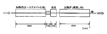
次いで、図1に示した装置を用いて、表5に示した条件で上記の直径1.2mmの線を焼入れ−焼戻し処理した(試験番号1〜35)。同様に、図1に示した装置を用いて、表6に示した条件で鋼A、鋼C、鋼D、鋼E、鋼K、鋼M、鋼N、鋼R、鋼T及び鋼Wの直径0.60mmの線を、焼入れ−焼戻し処理した(試験番号36〜49)。
【0098】
なお、焼入れのためのオーステナイト域への加熱及び焼戻しは、線の温度が目標温度±15℃の領域に15〜25秒保持されるようにした。ここで、上記の各熱処理とも、線を長さ100mに切断したものに対して実施し、線速(線の送り速度)は試験番号1〜11、13〜38及び40〜49については10m/分、試験番号12及び39については5m/分とした。
【0099】
鋼C、鋼G及び鋼Sの直径が1.2mmと0.60mmの線については、図2に示した装置を用いた流動層パテンティング処理も行った。この際の線速は10m/分とし、オーステナイト域への加熱は線の温度が940±15℃の領域に15〜25秒保持されるようにした。ここで、流動層の1ゾーンは550℃、2ゾーンは580℃に設定した。なお、このパテンティング処理も、線を長さ100mに切断したものに対して実施した。
【0100】
【表5】
【表6】
上記の各熱処理を施した長さ100mの線から引張試験片を切り出し、通常の方法で引張試験を実施した。更に、ミクロ組織の調査も行った。
【0103】
次いで、熱処理した各線について、引張試験片とミクロ観察試料に使用した残り全量を、各ダイスの減面率が平均で15%となるパススケジュールで、直径1.2mmの線については直径0.20mmまで、直径0.60mmの線については直径0.060mmまで湿式伸線加工を行った。この際、断線が2回以上発生した場合に伸線加工性が「劣る」と判定した。又、6回目の断線が発生した時点で伸線加工を中止した。
【0104】
湿式伸線加工して得られた直径がそれぞれ0.20mm及び0.060mmの線について通常の方法で引張試験を行った。
【0105】
表7〜12に前記の各試験結果をまとめて示す。なお、表11における試験番号50〜52は鋼C、鋼G及び鋼Sの直径が1.2mmのパテンティング処理した素線及びそれを伸線加工した直径が0.20mmの線の試験結果である。同様に、表12における試験番号53〜55は鋼C、鋼G及び鋼Sの直径が0.60mmのパテンティング処理した素線及びそれを伸線加工した直径が0.060mmの線の試験結果である。
【0106】
ここで、表7〜10中の試験番号1〜49において、焼戻しマルテンサイト(TM)が組織に占める割合は、次のようにして求めた。
【0107】
すなわち、先ず、焼入れしたままの組織を鏡面研磨した後、倍率を200倍として任意の4視野について観察した。その結果、試験番号1〜11、13〜38及び40〜49については、いずれの場合も焼入れままの組織が前記した「見かけ上のマルテンサイト組織」(つまり、マルテンサイトと残留オーステナイトの混合組織)だけからなり「α=100%」であることがわかった。一方、試験番号12及び39の場合には、それぞれ15%と20%のパーライトが含まれ、したがって、上記の各場合の「見かけ上のマルテンサイト組織」の割合であるα%はそれぞれ85%と80%であることがわかった。
【0108】
次に、X線回折による通常の方法で、焼入れしたままの組織に占める残留オーステナイト組織の割合を求めた。その結果、残留オーステナイト組織の割合(β%)は、最も少ない0%(試験番号1及び試験番号36の場合)から、最も多い20%(試験番号9、試験番号18、試験番号40及び試験番号43の場合)までの範囲にあることがわかった。
【0109】
既に述べたように、焼入れしたままの組織に占めるマルテンサイト組織の割合と焼戻し後の組織に占める焼戻しマルテンサイト組織の割合とは等しい。そこで最後に、前記▲1▼式を用いて各試験番号について、焼戻しマルテンサイト組織の割合(X%)を算出した。
【0110】
なお、表11及び表12中の試験番号52と試験番号55のミクロ組織にもマルテンサイトが含まれているが、これはパテンティング処理したままの素線のミクロ組織を示すものである。つまり、上記試験番号52と試験番号55におけるマルテンサイトは、焼戻しを施された焼戻しマルテンサイトではない。したがって、上記試験番号52と試験番号55における焼戻しマルテンサイトの割合は0%になる。
【0111】
【表7】
【表8】
【表9】
【表10】
【表11】
【表12】
表7〜12から、本発明で規定する条件から外れた試験番号1、3、5、8〜11、13、17〜22、24、28、30〜32、36、37、40、41、43〜45及び49〜55の場合には、伸線後の直径0.20mmと0.060mmの線の引張強さがそれぞれ3600MPaと4500MPaに達せず引張特性に劣るか、伸線加工中に2回以上断線して伸線加工性が低く生産性に劣ることが明らかである。
【0118】
これに対して、本発明で規定する条件を満たす試験番号の場合には、伸線後の直径0.20mmと0.060mmの線の引張強さはそれぞれ3600MPa以上と4500MPa以上であり、しかも伸線加工中の断線も1回以下で良好な伸線加工性を有し、生産性に優れることが明らかである。
【0119】
【発明の効果】
本発明の素線は、引張強さが1600MPa以上で伸線加工性に優れるので、これを伸線加工することでスチールコードやソーイングワイヤなどに用いられる強度の高い線を高い生産性の下に歩留り良く提供することができる。
【図面の簡単な説明】
【図1】実施例で直径が1.2mmと0.60mmの線を焼入れ−焼戻しするのに用いた装置を説明する図である。
【図2】実施例で直径が1.2mmと0.60mmの線をパテンティングするのに用いた流動層装置を説明する図である。[0001]
TECHNICAL FIELD OF THE INVENTION
The present invention relates to a wire and a wire for wire drawing. More specifically, for example, a radial tire of an automobile, a steel cord used as a reinforcing material for various industrial belts and hoses, and further, a steel wire for wire drawing and a steel wire suitable for applications such as sewing wires. The present invention relates to a steel wire obtained by drawing a wire.
[0002]
[Prior art]
Steel cords used as reinforcing materials for automobile radial tires, various belts and hoses, or sawing wires are generally subjected to several times of patenting treatment and elongation to a hot-rolled wire having a diameter of 5 to 6 mm. A wire that has been subjected to wire processing and then subjected to final patenting treatment to obtain a fine pearlite structure is used as a material (elementary wire), and a wire that has been subjected to final wire drawing is used.
[0003]
However, in the conventional production method, since the patenting treatment for obtaining the pearlite structure is a heat treatment using a lead bath or a fluidized bed, there are the following problems.
[0004]
In other words, lead baths are increasingly being refrained from use due to environmental considerations. Further, since the fluidized bed has a smaller heat transfer coefficient than that of the lead bath, the cooling rate is slow, and the characteristics of the material to be treated tend to vary on an industrial scale. In particular, it is extremely difficult to stabilize mechanical properties such as tensile strength by patenting an ultrafine wire having a diameter significantly less than 1.0 mm with a fluidized bed. Further, installation of the fluidized bed increases the equipment cost, so that an increase in product cost is inevitable.
[0005]
On the other hand, in recent years, steel cords and sawing wires have been required to have higher strength for various purposes such as reducing the weight of products and improving yields. The amount of processing in the steel has been increased, and a certain degree of high strength has been achieved. However, an increase in the C content in the steel and an increase in the amount of processing in the final drawing step cause a decrease in drawability, so that breakage occurs during the drawing, resulting in a large decrease in productivity and yield. Cause.
[0006]
In order to solve the above problem, Japanese Patent No. 2627373 discloses an ultrafine metal wire having a wire diameter of 0.01 to 0.50 mm and a steel structure having a carbon content of 0.60 to 1.20% by weight. A tempered martensite structure obtained by quenching and tempering a steel wire and having a tensile strength of 300 kgf / mm. 2 The "high-strength ultrafine metal wire" described above is disclosed. However, in the case of the technique proposed in this publication, as is clear from the description of the embodiment, in the case of a very fine wire having a wire diameter (diameter) of less than 0.10 mm, 430 kgf / mm. 2 Although a tensile strength of (4220 MPa) is obtained, for example, a steel wire used for a steel cord of a radial tire of an automobile and having a large target diameter of 0.15 to 0.40 mm is used. Has a tensile strength of at most 365 kgf / mm 2 (3580 MPa). This tensile strength is inferior to the conventional tensile strength of 3600 MPa class of a wire which is practically used after being subjected to final drawing after patenting.
[0007]
[Problems to be solved by the invention]
The present invention has been made in view of the above situation, and has as its object no environmental problems, and it can be manufactured stably at a low cost under industrially high productivity. An object of the present invention is to provide a wire for wire drawing having a diameter of 2.5 mm or less, a tensile strength of 1600 MPa or more, and a drawing of 30% or more, which are suitable for applications such as. Another object of the present invention is to provide a wire made of the above-mentioned element wire, particularly having a diameter of 0.15 to 0.40 mm and a tensile strength of 3600 MPa or more. Still another object of the present invention is to provide a wire using the above-mentioned element wire as a material, and particularly having a diameter of 0.02 to 0.10 mm and a tensile strength of 4500 MPa or more.
[0008]
[Means for Solving the Problems]
The gist of the present invention resides in a wire for wire drawing shown in the following (1) to (4) and a wire shown in (5) and (6).
[0009]
(1) In mass%, C: 0.5-0.9%, Si: 0.1-1.5%, Cr: 0.1-1.5%, and Si + Cr: 0.5-2. 0%, Mn: 0.1 to 1.0%, with the balance being Fe and impurities, Ti in the impurities is 0.003% or less, N is 0.010% or less, and P is 0.02% or less. , S is 0.015% or less, O (oxygen) is 0.0020% or less, 70% or more of the structure is a tempered martensite structure, the tensile strength is 1600 MPa or more, and the diameter of the drawing is 30% or more. Wire for wire drawing of 2.5 mm or less.
[0010]
(2) In mass%, C: 0.5-0.9%, Si: 0.1-1.5%, Cr: 0.1-1.5%, and Si + Cr: 0.5-2. 0%, Mn: 0.1 to 1.0%, Mo: 0.1 to 1.0%, W: 0.1 to 1.0%, V: 0.05 to 0.30% And Cu: one or more selected from 0.1 to 2.0%, with the balance being Fe and impurities, Ti in the impurities is 0.003% or less, N is 0.010% or less, P Is 0.02% or less, S is 0.015% or less, O (oxygen) is 0.0020% or less, 70% or more of the structure is a tempered martensite structure, the tensile strength is 1600 MPa or more, and the drawing is 30 or less. % Or more, a wire for wire drawing with a diameter of 2.5 mm or less.
[0011]
(3) In mass%, C: 0.5-0.9%, Si: 0.1-1.5%, Cr: 0.1-1.5%, and Si + Cr: 0.5-2. 0%, Mn: 0.1 to 1.0%, Nb: 0.005 to 0.03%, B: 0.0003 to 0.005%, and Al: 0.005 to 0.030% , The balance consisting of Fe and impurities, wherein Ti in the impurities is 0.003% or less, N is 0.010% or less, P is 0.02% or less, and S is 0.1% or less. 015% or less, O (oxygen) is 0.0020% or less, 70% or more of the structure is a tempered martensite structure, the tensile strength is 1600 MPa or more, and the drawing is 30% or more and the diameter is 2.5 mm or less. Wire for wire drawing.
[0012]
(4) In mass%, C: 0.5-0.9%, Si: 0.1-1.5%, Cr: 0.1-1.5%, and Si + Cr: 0.5-2. 0%, Mn: 0.1 to 1.0%, Mo: 0.1 to 1.0%, W: 0.1 to 1.0%, V: 0.05 to 0.30% And Cu: at least one selected from 0.1 to 2.0%, and Nb: 0.005 to 0.03%, B: 0.0003 to 0.005%, and Al: 0.005 to 0. 0.030% or less, with the balance being Fe and impurities, Ti in the impurities is 0.003% or less, N is 0.010% or less, P is 0.02% or less, and S Is 0.015% or less, O (oxygen) is 0.0020% or less, 70% or more of the structure is a tempered martensite structure, the tensile strength is 1600 MPa or more, and the drawing is 30%. Wire for wire drawing of an upper diameter of 2.5mm or less.
[0013]
(5) A wire having a tensile strength of 3600 MPa or more drawn to a diameter of 0.15 to 0.40 mm using the wire for wire drawing according to any of (1) to (4) above. .
[0014]
(6) A wire having a tensile strength of 4500 MPa or more drawn to a diameter of 0.02 to 0.10 mm using the wire for wire drawing according to any of (1) to (4) above. .
[0015]
The “tempered martensite structure” in the present invention refers to a phase in which martensite is transformed by cooling (quenching) the austenite phase (that is, martensite) is Ac. 1 It refers to a structure in which carbides are precipitated and heated and tempered to a temperature below the point.
[0016]
Here, it is known that the volume ratio of a certain phase is equal to the area ratio evaluated from the microstructure. Therefore, the ratio of the tempered martensite in the structure is as-quenched by the following method, for example. What is necessary is just to determine from the ratio of the martensite organization to the organization of the above.
[0017]
First, the as-quenched structure is mirror-polished and then observed with an optical microscope. Specifically, for example, a photograph is taken in any four visual fields at a magnification of 200, and the ratio of the martensite structure in the photograph is measured by a normal image processing method or the like. Incidentally, when the steel whose chemical composition is within the range of the content specified in the present invention is quenched and quenched, in addition to the martensite structure, there is also a structure called retained austenite in which austenite remains untransformed, Observation with an optical microscope makes it difficult to distinguish between the retained austenite structure and the martensite structure.
[0018]
Therefore, from the observation of the quenched and quenched steel by an optical microscope, the ratio of ferrite and pearlite in the structure was determined, and the remainder was `` apparent martensite structure '', that is, the martensite structure and the retained austenite structure Ratio (α%).
[0019]
Next, the ratio (β%) of the retained austenite structure to the structure as-quenched by the ordinary method by X-ray diffraction is determined.
[0020]
Finally, the ratio (X%) of the martensite structure to the as-quenched structure is calculated from the following equation (1). Here, the as-quenched martensite structure is Ac 1 The material is heated to a temperature below the temperature and tempered to form a tempered martensite structure. In other words, the ratio of the martensite structure in the as-quenched structure is equal to the ratio of the tempered martensite structure in the structure after tempering, and the ratio of the martensite structure in the as-quenched structure obtained from equation (1). Is the ratio of the tempered martensite structure to the structure after tempering.
[0021]
X = α − {(α × β) / 100} (1).
[0022]
Hereinafter, the inventions relating to the wire or wire for wire drawing described in (1) to (6) above are referred to as inventions (1) to (6), respectively.
[0023]
The present inventors have obtained wire for wire drawing which is excellent in wire drawing workability and is suitable for applications such as steel cords and sawing wires, and has a high strength fine wire or ultra fine wire using the above-mentioned wire as a material. In order to obtain, we conducted repeated surveys and studies. As a result, the following findings were obtained.
[0024]
(A) High-carbon steel strands that have undergone quenching and tempering treatment under appropriate conditions and have a martensite structure in at least 70% of the structure (ie, tempered martensite structure) have a pearlite structure or bainite structure. Has a higher tensile strength and a reduction of 30% or more as compared with the high-carbon steel strand of No.
[0025]
(B) When the high-carbon steel wire of each of the above structures is drawn by the same processing amount, the tensile strength when 70% or more of the structure is a tempered martensite structure has a tensile strength of a pearlite structure or a bainite structure. Greater than the tensile strength of the case.
[0026]
(C) In order to increase the tensile strength of the high-carbon steel wire whose tempered martensite structure accounts for 70% or more of the structure and the tensile strength of the high-carbon steel wire obtained by drawing this wire, it is necessary to use cementite. It is most effective to cause fine precipitation of Si. For this purpose, Si and Cr may be positively contained in steel.
[0027]
(D) In a high-carbon steel wire actively containing Si and Cr, the tensile strength when 70% or more of the structure is a tempered martensite structure is the tensile strength when the structure is pearlite. Can be greatly increased by setting the tempering temperature to 375 to 450 ° C.
[0028]
(E) When the tempering martensite structure occupies 70% or more of the structure when plating a high-carbon steel wire, if the temperature of the high-carbon steel wire to be processed exceeds 450 ° C. May be contained at least one of Mo, W, V and Cu, which precipitates secondarily, to suppress a decrease in tensile strength. In this case, since the tempering can be performed by the heat treatment during the plating process, the plating process may be performed directly without performing the tempering after the quenching process.
[0029]
The present invention has been completed based on the above findings.
[0030]
BEST MODE FOR CARRYING OUT THE INVENTION
Hereinafter, each requirement of the present invention will be described in detail. In addition, "%" of the content of each element means "% by mass".
[0031]
(A) Chemical composition
In the present invention, the chemical composition of the strands and wires is limited to the following ranges in order to ensure drawability, impart properties to the final product, and ensure industrial productivity.
[0032]
C: 0.5 to 0.9%
C is an element effective for increasing the strength of the wire. When the content is less than 0.5%, wire drawing with a true strain of 3.6, which is a general method of manufacturing a steel cord for an automobile radial tire, for example, from 1.2 mm to 0.1 mm in diameter. In the wire drawing to 2 mm, the tensile strength does not reach 3600 MPa after the final wire drawing. On the other hand, if the content of C is too large, quenching will occur upon quenching, making wire drawing difficult. In particular, when the content of C exceeds 0.9%, the occurrence of burning cracks becomes remarkable, and the wire drawing cannot be performed. Therefore, the C content is set to 0.5 to 0.9%.
[0033]
The true strain (ε) is the diameter (d) of the wire or wire before wire drawing. 0 ) And the diameter of the drawn wire (d), ε = 2 log e (D 0 / D).
[0034]
Si: 0.1 to 1.5%
Si has a great effect of finely dispersing cementite, and particularly has an effect of greatly increasing the strength after tempering by being contained in combination with Cr described later. Si is also an element necessary as a deoxidizing agent. In order to sufficiently exhibit the effect as a deoxidizing agent, it is necessary to contain 0.1% or more of Si. On the other hand, when the content of Si exceeds 1.5%, precipitation of cementite during tempering is significantly delayed, which causes a decrease in industrial productivity. Therefore, the content of Si is set to 0.1 to 1.5%.
[0035]
Cr: 0.1-1.5%
Cr has a great effect of finely dispersing cementite, and particularly has an effect of greatly increasing the strength after tempering by being contained in combination with the above-mentioned Si. However, if the content is less than 0.1%, the effect of addition is poor, while if it exceeds 1.5%, precipitation of cementite during tempering is significantly slowed down, leading to a decrease in industrial productivity. Therefore, the content of Cr is set to 0.1 to 1.5%.
[0036]
Si + Cr: 0.5 to 2.0%
As described above, Si and Cr have a great effect of finely dispersing cementite. In particular, by incorporating both elements in combination, the strength after tempering can be significantly increased. However, when the value of Si + Cr, which is the sum of the contents, is less than 0.5%, the above effect is difficult to obtain. On the other hand, when the value of Si + Cr exceeds 2.0%, precipitation of cementite during tempering is significantly delayed, which causes a decrease in industrial productivity. Therefore, the value of Si + Cr, which is the sum of the contents of Si and Cr, is set to 0.5 to 2.0%.
[0037]
Mn: 0.1-1.0%
Mn has an effect of fixing S in steel as MnS and preventing hot embrittlement in addition to an effect of increasing strength. However, if the content is less than 0.1%, it is difficult to obtain the above effects. On the other hand, if the content exceeds 1.0%, the above effect is saturated and the cost is increased. Therefore, the content of Mn is set to 0.1 to 1.0%.
[0038]
In the present invention, the contents of Ti, N, P, S and O (oxygen) as impurity elements are limited as follows from the viewpoint of ensuring the wire drawing workability.
[0039]
Ti: 0.003% or less
Ti combines with N to form TiN in steel. This TiN is likely to be a starting point of disconnection during wire drawing. In particular, when the content of Ti exceeds 0.003%, TiN is coarsened, and disconnection frequently occurs during wire drawing. Therefore, the Ti content is set to 0.003% or less.
[0040]
N: 0.010% or less
N adheres to dislocations during cold drawing and increases the strength of the wire, but decreases the drawability. In particular, if the content exceeds 0.010%, the wire drawing workability is significantly reduced. Therefore, the content of N is set to 0.010% or less.
[0041]
P: 0.02% or less
P easily segregates at the grain boundary and makes the wire brittle, so that the wire drawing workability is reduced. In particular, if the content exceeds 0.02%, the wire drawing workability is significantly reduced. Therefore, the content of P is set to 0.02% or less.
[0042]
S: 0.015% or less
S combines with Mn to form MnS in steel. This MnS tends to be a starting point of disconnection during wire drawing. In particular, when the content of S exceeds 0.015%, a large amount of MnS is generated, so that the wire drawing workability is significantly reduced. Therefore, the content of S is set to 0.015% or less.
[0043]
O (oxygen): 0.0020% or less
O combines with Al, Si, etc. in steel to form oxide-based inclusions, thereby deteriorating drawability. In particular, when the content of O exceeds 0.0020%, the oxide-based inclusions are coarsened, so that the wire drawing workability is significantly reduced, and the wire is frequently broken during the wire drawing process. Therefore, the content of O is set to 0.0020% or less.
[0044]
The component elements other than Fe contained in the strand according to the present invention may be only the elements from C to O (oxygen) as in the invention of (1). However, in addition to the above components, if necessary, one or more selected from Mo, W, V and Cu, and / or one or more selected from Nb, B and Al are selectively contained. Can be. That is, the elements Mo, W, V, Cu, Nb, B, and Al may be added and contained as optional additional elements.
[0045]
Hereinafter, the above-mentioned optional elements will be described.
[0046]
First, Mo, W, V, and Cu, all of which have the effect of increasing the strength when added, will be described.
[0047]
Mo: 0.1 to 1.0%
Mo, when added, has the effect of precipitating finely as carbide during tempering and increasing the strength. To ensure this effect, it is preferable that the content of Mo be 0.1% or more. However, if the content exceeds 1.0%, the above effect is saturated and the cost is increased. Therefore, when Mo is added, its content is preferably 0.1 to 1.0%.
[0048]
W: 0.1-1.0%
W, when added, has the effect of increasing the strength by precipitating finely as carbides during tempering. In order to surely obtain this effect, the content of W is preferably set to 0.1% or more. However, if the content exceeds 1.0%, the above effect is saturated and the cost is increased. Therefore, when W is added, its content is preferably set to 0.1 to 1.0%.
[0049]
V: 0.05 to 0.30%
V, if added, has the effect of increasing the strength by finely precipitating as carbides and nitrides during tempering. In order to surely obtain this effect, it is preferable that the content of V is 0.05% or more. However, if the content exceeds 0.30%, coarse carbides and nitrides remain even when the steel is heated to the austenite region for quenching, so that disconnection frequently occurs during wire drawing. Therefore, when V is added, its content is preferably set to 0.05 to 0.30%.
[0050]
Cu: 0.1 to 2.0%
If added, Cu has a function of precipitating finely during tempering and increasing the strength. To ensure this effect, the content of Cu is preferably set to 0.1% or more. However, if the content exceeds 2.0%, segregation at crystal grain boundaries causes cracks and flaws to be noticeable during hot working such as slab rolling of steel ingots and hot rolling of wire rods. Therefore, when Cu is added, its content is preferably set to 0.1 to 2.0%.
[0051]
In place of a part of Fe in the chemical composition of the wire according to the invention of (1), any one or more of the above-mentioned Mo, W, V and Cu are compounded and contained, whereby (2) The chemical composition of the strand according to the invention is obtained.
[0052]
Next, Nb, B, and Al, all of which have the effect of enhancing the drawability when added, will be described.
[0053]
Nb: 0.005 to 0.03%
When Nb is added, it has an effect of making austenite crystal grains fine and improving drawability. In order to surely obtain this effect, the content of Nb is desirably 0.005% or more. However, if the content exceeds 0.03%, coarse carbides and nitrides remain even when heated to the austenite region for quenching, so that disconnection frequently occurs during wire drawing. Therefore, when adding Nb, its content is preferably set to 0.005 to 0.03%.
[0054]
B: 0.0003-0.005%
B, when added, combines with N to form BN, thereby reducing the amount of solute N and enhancing wire drawing workability. To ensure this effect, the content of B is preferably set to 0.0003% or more. However, if the content exceeds 0.005%, coarse BN is generated, and disconnection frequently occurs during wire drawing. Therefore, when B is added, its content is preferably set to 0.0003 to 0.005%.
[0055]
Al: 0.005 to 0.030%
Al, when added, combines with N to form AlN, has the effect of reducing austenite crystal grains, reducing solid solution N, and improving drawability. To ensure this effect, the content of Al is preferably set to 0.005% or more. However, when Al is contained in excess of 0.030%, Al 2 O 3 The oxide-based inclusions containing as a main component coarsen, and wire breakage frequently occurs during wire drawing. Therefore, when Al is added, the content is preferably set to 0.005 to 0.030%.
[0056]
The invention according to (3) can be realized by combining at least one of Nb, B and Al in place of a part of Fe in the chemical composition of the wire according to the invention according to (1). The chemical composition of such a strand is obtained.
[0057]
Further, instead of a part of Fe in the chemical composition of the strand according to the invention of (1), any one or more of Mo, W, V and Cu described above, and Nb, B and Al The chemical composition of the strand according to the invention of (4) is obtained by combining any one or more of them.
[0058]
(B) Microstructure
The microstructure of the high carbon steel includes a pearlite structure, a bainite structure and a martensite structure.
[0059]
The present inventors produced a test material having a different microstructure having a diameter of 1.2 mm and a length of 1000 mm using steel C shown in Table 1.
[0060]
[Table 1]
That is, a test material having a length of 1000 mm was sampled from a wire having a diameter of 1.2 mm obtained by wire drawing, heat-treated under different conditions, and then drawn by a usual method to a diameter of 0.20 mm. Table 2 shows the microstructure and tensile properties of the heat-treated wire (element wire) having a diameter of 1.2 mm, and the tensile properties of a drawn wire having a diameter of 0.20 mm. Here, the heat treatment conditions 1 to 8 in Table 2 are as shown below.
[0062]
Condition 1: heated to 920 ° C. and held for 20 seconds, then immersed in a 580 ° C. lead bath and held for 20 seconds, and allowed to cool in air after holding.
[0063]
Condition 2: After heating to 920 ° C. and holding for 20 seconds, it was immersed in a 500 ° C. lead bath and held for 60 seconds, and then allowed to cool in air.
[0064]
Condition 3: heated to 860 ° C., held for 60 seconds, oil quenched, then tempered at 350 ° C. for 3 minutes, and then allowed to cool in the air.
[0065]
Condition 4: oil quenching after heating to 860 ° C. and holding for 60 seconds, followed by tempering at 375 ° C. for 3 minutes and then cooling in the air.
[0066]
Condition 5: Heated to 1150 ° C., held for 60 seconds, oil quenched, then tempered at 375 ° C. for 3 minutes, and allowed to cool in air.
[0067]
Condition 6: heating to 860 ° C., holding for 60 seconds, oil quenching, then tempering at 400 ° C. for 3 minutes, and then cooling in the air.
[0068]
Condition 7: heating to 860 ° C., holding for 60 seconds, oil quenching, tempering at 450 ° C. for 3 minutes, and then cooling in the air.
[0069]
Condition 8: heating to 860 ° C., holding for 60 seconds, oil quenching, tempering at 600 ° C. for 3 minutes, and then cooling in the air.
[0070]
In the case of heat treatment under the conditions 1 and 3, the wire was frequently broken and could not be drawn to 0.20 mm, and the tensile test was not performed.
[0071]
[Table 2]
From Table 2, it is found that the martensite structure in which the wire structure has been subjected to quenching and tempering treatment under appropriate conditions (that is, the tempered martensite structure is subjected to the heat treatment under the conditions 4, 6, and 7 in Table 2). ), The tensile strength of the wire is greater than the tensile strength of the pearlite or bainite structure. The same can be said for the tensile strength of a wire obtained by drawing these wires with the same processing amount.
[0073]
As described above, the “tempered martensite structure” in the present invention means that a phase transformed into martensite by cooling (quenching) an austenite phase (that is, martensite) is Ac 1 It refers to a structure in which carbides are precipitated and heated and tempered to a temperature below the point.
[0074]
In heat treatment conditions 3 to 8 in Table 2, the ratio of tempered martensite to the structure was determined as follows.
[0075]
That is, first, the as-quenched structure was mirror-polished, and then observed in four arbitrary visual fields at a magnification of 200 times. As a result, in any of the heat treatment conditions 3 to 8, the as-quenched structure is composed of only the aforementioned “apparent martensite structure” (that is, a mixed structure of martensite and residual austenite), and “α = 100%” It turned out to be. Next, the ratio of the retained austenite structure to the as-quenched structure was determined by an ordinary method using X-ray diffraction. As a result, it was found that “β = 10%” in any of the heat treatment conditions 3 to 8.
[0076]
As described above, the ratio of the martensite structure in the as-quenched structure is equal to the ratio of the tempered martensite structure in the structure after tempering. Then, finally, the ratio (X%) of the tempered martensite structure was calculated using the above formula (1), and it was found that “X = 90%” in any of the heat treatment conditions 3 to 8.
[0077]
As is clear from the above-described method of deriving the ratio of the tempered martensite structure to the structure, in each of the 10% structures other than the tempered martensite under the heat treatment conditions 3 to 8 in Table 2, the retained austenite was subjected to the tempering treatment. This is the tissue that has been decomposed and received.
[0078]
The tempered martensite structure is obtained by heating steel to the austenitic region using a general heating furnace, quenching it using an appropriate cooling medium such as oil or water, and then tempering using a general heat treatment furnace. Therefore, it is not necessary to use a lead bath or a fluidized bed for patenting unlike the pearlite structure. In addition, the strand having a tempered martensite structure can ensure stable high strength and good drawability. Here, when the ratio of the tempered martensite in the structure of the wire reaches 70% or more, the characteristics of the wire are mostly controlled by the characteristics of the tempered martensite. Therefore, 70% or more of the structure of the strand according to the present invention is defined as a tempered martensite structure. Here, the ratio of the tempered martensite structure may be 70% or more, and the upper limit may be the maximum amount of martensite obtained according to the chemical composition and the heat treatment conditions. The structure other than tempered martensite does not need to be defined, and may be a structure in which retained austenite, ferrite, bainite, or pearlite has been subjected to a tempering treatment.
[0079]
In order to make the structure of the element wire a tempered martensite structure, for example, after heating to an austenitic region of 850 to 950 ° C. depending on the steel composition, quenching is performed using a suitable cooling medium such as oil or water, Thereafter, tempering may be performed at 375 to 600 ° C. according to the steel composition. For example, when the steel composition is the chemical composition according to the invention of (1) or (3), it may be tempered at 375 to 450 ° C., or the chemical composition according to the invention of (2) or (4). In the case of a composition, tempering treatment may be performed at 450 to 600 ° C.
[0080]
(C) Tensile properties and diameter of strand
The higher the tensile strength of the strand, the more the amount of wire drawing can be reduced, which is industrially advantageous.
[0081]
When the tensile strength of the strand is less than 1600 MPa, the wire is drawn with a true strain of 3.6, which is a general method of manufacturing a steel cord for an automobile radial tire, for example, from 1.2 mm in diameter to 0.1 mm in diameter. In the wire drawing to 2 mm, the tensile strength does not reach 3600 MPa. Therefore, the tensile strength of the strand was specified to be 1600 MPa or more. When it is desired to further increase the tensile strength after wire drawing or to reduce the amount of processing at the time of wire drawing, the tensile strength of the strand is desirably 1800 MPa or more. A more desirable tensile strength of the strand is 1900 MPa or more.
[0082]
On the other hand, when the tensile strength of the strand increases, the drawability tends to decrease. As an index of the wire drawing workability, a drawing in a tensile test can be used. If the drawing is less than 30%, a break may occur in the wire drawing with the above-mentioned true strain of 3.6. . Therefore, the aperture of the wire is specified as 30% or more. In order to perform wire drawing more stably, it is preferable that the drawing be 40% or more.
[0083]
The true strain (ε) is the diameter (d) of the wire or wire before wire drawing. 0 ) And the diameter of the drawn wire (d), ε = 2 log e (D 0 / D) is as described above.
[0084]
If the diameter of the strand exceeds 2.5 mm, quenching cracks are likely to occur during quenching, and breakage frequently occurs during wire drawing. Therefore, the diameter of the wire is specified to be 2.5 mm or less. The lower limit of the diameter of the strand is not particularly specified, but if it is less than 0.2 mm, it becomes extremely easy to break during the heat treatment. For this reason, it is preferable that the diameter of the strand be 0.2 mm or more.
[0085]
(D) Wire diameter and tensile strength
In the wires according to the inventions (5) and (6), the diameter and the tensile strength are also specified.
[0086]
First, the wire according to the invention of (5) has a diameter of 0.15 to 0.40 mm and a tensile strength of 3600 MPa or more. This is for the following reason.
[0087]
The diameter of a wire usually used for a steel cord of an automobile radial tire is 0.15 to 0.40 mm, and the tensile strength of a conventional wire practically used after final drawing after patenting treatment is 3600 MPa. There are many things up to class. Therefore, in the wire according to the invention of (5), in order to secure the same size and tensile strength as the wire used for the steel cord of the current automobile radial tire, the diameter is 0.15 to 0.40 mm, The tensile strength was specified as 3600 MPa or more. Since the higher the tensile strength is, the better the weight of the final product is, the tensile strength of the wire according to the invention (5) is preferably 3800 MPa or more.
[0088]
Next, the wire according to the invention of (6) has a diameter of 0.02 to 0.10 mm and a tensile strength of 4500 MPa or more. This is for the following reason.
[0089]
The diameter of an ultrafine wire used for a saw wire or the like is 0.10 mm or less, and the tensile strength of a saw wire generally used at present is less than 4500 MPa. If the diameter of the wire is less than 0.02 mm, the workability is extremely reduced. For this reason, in the wire according to the invention of (6), in order to secure the same size as the current wire for saw wire, higher tensile strength, and good workability, the wire has a diameter of 0.02 to 0.02. 0.10 mm, and the tensile strength was specified to be 4500 MPa or more.
[0090]
Hereinafter, the present invention will be described in detail with reference to examples.
[0091]
【Example】
Steels A to Z having the chemical compositions shown in Tables 3 and 4 were melted using a 150 kg vacuum melting furnace. In addition, the steel C of Table 1 was described again in the above table.
[0092]
Steel B, steel C, steel G, steel I to K, steel Q to U and steel X to Z in the above table are steels of the examples of the present invention whose chemical composition is within the range defined by the present invention. is there. On the other hand, steel A, steel DF, steel H, steel LP, steel V, and steel W are steels of comparative examples in which any of the components is out of the range of the content specified in the present invention.
[0093]
[Table 3]
[Table 4]
These steels are hot forged into a round bar having a diameter of 90 mm by a usual method, and then heated to 1180 ° C., and then hot-rolled into a wire having a diameter of 5.5 mm at a rolling finish temperature of 880 ° C. Cooled by the method.
[0096]
The wire obtained in this manner is subjected to pickling, lubrication, and wire drawing by a normal method to obtain a wire having a diameter of 2.5 mm, and further subjected to a patenting process and a wire drawing by a normal method. It was a 1.2 mm line. In addition, about the wire of steel A, steel C, steel D, steel E, steel G, steel K, steel M, steel N, steel R to T, and steel W, half of the wire was further drawn to 0.60 mm. Line.
[0097]
Next, the wire having a diameter of 1.2 mm was quenched and tempered using the apparatus shown in FIG. 1 under the conditions shown in Table 5 (test numbers 1 to 35). Similarly, using the apparatus shown in FIG. 1, under the conditions shown in Table 6, steel A, steel C, steel D, steel E, steel K, steel M, steel N, steel R, steel T, and steel W A wire having a diameter of 0.60 mm was quenched and tempered (test numbers 36 to 49).
[0098]
The heating and tempering to the austenite region for quenching were performed so that the temperature of the wire was maintained in the range of the target temperature ± 15 ° C. for 15 to 25 seconds. Here, each of the above heat treatments was carried out on a wire cut to a length of 100 m, and the linear speed (line feed speed) was 10 m / m for test numbers 1 to 11, 13 to 38 and 40 to 49. Min, and test numbers 12 and 39 were 5 m / min.
[0099]
Fluid bed patenting treatment using the apparatus shown in FIG. 2 was also performed on the lines of steel C, steel G and steel S having diameters of 1.2 mm and 0.60 mm. At this time, the linear speed was set to 10 m / min, and the heating to the austenite region was performed so that the temperature of the line was maintained in a range of 940 ± 15 ° C. for 15 to 25 seconds. Here, one zone of the fluidized bed was set at 550 ° C., and two zones were set at 580 ° C. In addition, this patenting process was also performed on the line cut to a length of 100 m.
[0100]
[Table 5]
[Table 6]
A tensile test piece was cut out from a line having a length of 100 m subjected to each of the heat treatments described above, and a tensile test was performed by an ordinary method. In addition, the microstructure was investigated.
[0103]
Next, for each of the heat-treated wires, the remaining amount used for the tensile test piece and the micro-observation sample was determined according to a pass schedule in which the area reduction rate of each die was 15% on average, and for the wire having a diameter of 1.2 mm, the diameter was 0.20 mm. , A wire having a diameter of 0.60 mm was wet drawn to a diameter of 0.060 mm. At this time, when the disconnection occurred twice or more, it was determined that the wire drawing workability was “poor”. The wire drawing was stopped when the sixth disconnection occurred.
[0104]
Tensile tests were performed on wires having diameters of 0.20 mm and 0.060 mm, respectively, obtained by wet wire drawing in a usual manner.
[0105]
Tables 7 to 12 summarize the results of the above-described tests. In addition, the test numbers 50-52 in Table 11 are the test results of the wire which the steel C, the steel G, and the steel S were subjected to the patenting process with the diameter of 1.2 mm, and the wire which was drawn and the diameter was 0.20 mm. is there. Similarly, the test numbers 53 to 55 in Table 12 are the test results of the patented wire having a diameter of 0.60 mm of the steel C, the steel G and the steel S and the wire having a diameter of 0.060 mm obtained by drawing the wire. It is.
[0106]
Here, in Test Nos. 1 to 49 in Tables 7 to 10, the ratio of tempered martensite (TM) to the structure was determined as follows.
[0107]
That is, first, the as-quenched structure was mirror-polished, and then observed in four arbitrary visual fields at a magnification of 200 times. As a result, as for the test numbers 1 to 11, 13 to 38 and 40 to 49, the as-quenched structure was the above-mentioned “apparent martensite structure” (that is, a mixed structure of martensite and residual austenite) in each case. It was found that “α = 100%”. On the other hand, in the case of Test Nos. 12 and 39, 15% and 20% of pearlite were contained, respectively. Therefore, in each of the above cases, the α% which is the ratio of “apparent martensite structure” was 85%. It turned out to be 80%.
[0108]
Next, the ratio of the retained austenite structure to the as-quenched structure was determined by an ordinary method using X-ray diffraction. As a result, the ratio (β%) of the retained austenite structure was from the smallest 0% (in the case of Test No. 1 and Test No. 36) to the largest 20% (Test No. 9, Test No. 18, Test No. 40 and Test No. 36). 43).
[0109]
As described above, the ratio of the martensite structure in the as-quenched structure is equal to the ratio of the tempered martensite structure in the structure after tempering. Therefore, finally, the ratio (X%) of the tempered martensite structure was calculated for each test number using the above formula (1).
[0110]
The microstructures of Test No. 52 and Test No. 55 in Tables 11 and 12 also contain martensite, which shows the microstructure of the as-patented wire. That is, the martensite in Test Nos. 52 and 55 is not tempered martensite. Therefore, the ratio of tempered martensite in Test Nos. 52 and 55 is 0%.
[0111]
[Table 7]
[Table 8]
[Table 9]
[Table 10]
[Table 11]
[Table 12]
From Tables 7 to 12, test numbers 1, 3, 5, 8 to 11, 13, 17 to 22, 24, 28, 30 to 32, 36, 37, 40, 41, and 43 deviated from the conditions specified in the present invention. In the case of ~ 45 and 49 ~ 55, the tensile strength of the 0.20mm and 0.060mm diameter wires after drawing does not reach 3600MPa and 4500MPa respectively, resulting in poor tensile properties or twice during drawing. It is clear that the wire is broken and the wire drawing workability is low and the productivity is inferior.
[0118]
On the other hand, in the case of the test number satisfying the conditions specified in the present invention, the tensile strengths of the 0.20 mm and 0.060 mm diameter wires after drawing are 3600 MPa or more and 4500 MPa or more, respectively. It is clear that the wire has good wire drawing workability even when the wire is broken once or less, and is excellent in productivity.
[0119]
【The invention's effect】
Since the strand of the present invention has excellent tensile workability with a tensile strength of 1600 MPa or more, it is possible to obtain a high-strength wire used for a steel cord or a sawing wire under high productivity by drawing. It can be provided with good yield.
[Brief description of the drawings]
FIG. 1 is a diagram illustrating an apparatus used for quenching and tempering wires having a diameter of 1.2 mm and 0.60 mm in an embodiment.
FIG. 2 is a view for explaining a fluidized bed apparatus used for patenting lines having diameters of 1.2 mm and 0.60 mm in Examples.
Claims (6)
Priority Applications (1)
| Application Number | Priority Date | Filing Date | Title |
|---|---|---|---|
| JP2002168979A JP2004011002A (en) | 2002-06-10 | 2002-06-10 | Element wire for drawing and wire |
Applications Claiming Priority (1)
| Application Number | Priority Date | Filing Date | Title |
|---|---|---|---|
| JP2002168979A JP2004011002A (en) | 2002-06-10 | 2002-06-10 | Element wire for drawing and wire |
Publications (1)
| Publication Number | Publication Date |
|---|---|
| JP2004011002A true JP2004011002A (en) | 2004-01-15 |
Family
ID=30435741
Family Applications (1)
| Application Number | Title | Priority Date | Filing Date |
|---|---|---|---|
| JP2002168979A Pending JP2004011002A (en) | 2002-06-10 | 2002-06-10 | Element wire for drawing and wire |
Country Status (1)
| Country | Link |
|---|---|
| JP (1) | JP2004011002A (en) |
Cited By (9)
| Publication number | Priority date | Publication date | Assignee | Title |
|---|---|---|---|---|
| WO2006059784A1 (en) * | 2004-11-30 | 2006-06-08 | Nippon Steel Corporation | Steel and steel wire for high strength spring |
| DE102009051427A1 (en) * | 2009-10-30 | 2011-05-12 | Saarstahl Aktiengesellschaft | Steel alloy and use of such an alloyed steel |
| JP2011522113A (en) * | 2008-04-30 | 2011-07-28 | ナムローゼ・フェンノートシャップ・ベーカート・ソシエテ・アノニム | Steel filament patented with bismuth |
| KR101359064B1 (en) | 2012-10-24 | 2014-02-06 | 주식회사 포스코 | Fine steel wire having excellent drawing property and method for manufacturing therof |
| CN103805861A (en) * | 2014-02-11 | 2014-05-21 | 江苏省沙钢钢铁研究院有限公司 | High-carbon steel wire and preparation method thereof |
| JP2015193896A (en) * | 2014-03-31 | 2015-11-05 | 新日鐵住金株式会社 | Method for manufacturing extra fine brass plating steel wire |
| JP2015535882A (en) * | 2012-09-07 | 2015-12-17 | コンパニー ゼネラール デ エタブリッスマン ミシュラン | Highly pullable steel wire having a carbon mass percentage value of 0.5% or more and 0.6% or less |
| WO2018230717A1 (en) * | 2017-06-15 | 2018-12-20 | 新日鐵住金株式会社 | Rolled wire for spring steel |
| JP2023508314A (en) * | 2019-12-20 | 2023-03-02 | ポスコホールディングス インコーポレーティッド | Wire rod for ultra-high strength spring, steel wire and manufacturing method thereof |
-
2002
- 2002-06-10 JP JP2002168979A patent/JP2004011002A/en active Pending
Cited By (15)
| Publication number | Priority date | Publication date | Assignee | Title |
|---|---|---|---|---|
| WO2006059784A1 (en) * | 2004-11-30 | 2006-06-08 | Nippon Steel Corporation | Steel and steel wire for high strength spring |
| KR100851083B1 (en) * | 2004-11-30 | 2008-08-08 | 신닛뽄세이테쯔 카부시키카이샤 | Steel and steel wire for high strength spring |
| US10131973B2 (en) | 2004-11-30 | 2018-11-20 | Nippon Steel & Sumitomo Metal Corporation | High strength spring steel and steel wire |
| JP2011522113A (en) * | 2008-04-30 | 2011-07-28 | ナムローゼ・フェンノートシャップ・ベーカート・ソシエテ・アノニム | Steel filament patented with bismuth |
| US9169528B2 (en) | 2008-04-30 | 2015-10-27 | Nv Bekaert Sa | Steel filament patented in bismuth |
| DE102009051427A1 (en) * | 2009-10-30 | 2011-05-12 | Saarstahl Aktiengesellschaft | Steel alloy and use of such an alloyed steel |
| JP2015535882A (en) * | 2012-09-07 | 2015-12-17 | コンパニー ゼネラール デ エタブリッスマン ミシュラン | Highly pullable steel wire having a carbon mass percentage value of 0.5% or more and 0.6% or less |
| KR101359064B1 (en) | 2012-10-24 | 2014-02-06 | 주식회사 포스코 | Fine steel wire having excellent drawing property and method for manufacturing therof |
| CN103805861A (en) * | 2014-02-11 | 2014-05-21 | 江苏省沙钢钢铁研究院有限公司 | High-carbon steel wire and preparation method thereof |
| US10316386B2 (en) | 2014-02-11 | 2019-06-11 | Institute of Research of Iron and Steel, Jiangsu Province/Sha-Steel, Co. Ltd. | High-carbon steel wire rod and preparation method therefor |
| JP2015193896A (en) * | 2014-03-31 | 2015-11-05 | 新日鐵住金株式会社 | Method for manufacturing extra fine brass plating steel wire |
| WO2018230717A1 (en) * | 2017-06-15 | 2018-12-20 | 新日鐵住金株式会社 | Rolled wire for spring steel |
| JP6447799B1 (en) * | 2017-06-15 | 2019-01-09 | 新日鐵住金株式会社 | Rolled wire rod for spring steel |
| US11118251B2 (en) | 2017-06-15 | 2021-09-14 | Nippon Steel Corporation | Rolled wire rod for spring steel |
| JP2023508314A (en) * | 2019-12-20 | 2023-03-02 | ポスコホールディングス インコーポレーティッド | Wire rod for ultra-high strength spring, steel wire and manufacturing method thereof |
Similar Documents
| Publication | Publication Date | Title |
|---|---|---|
| US8168011B2 (en) | High-strength steel wire excellent in ductility and method of manufacturing the same | |
| EP2090671A1 (en) | High-strength wire rod excelling in wire drawability and process for producing the same | |
| JP2004137597A (en) | Hot rolled wire rod in which heat treatment before wire drawing can be eliminated, and having excellent wire drawability | |
| JPWO2007139234A1 (en) | High ductility high carbon steel wire | |
| JP2005206853A (en) | High carbon steel wire rod having excellent wire drawability, and production method therefor | |
| JP2004091912A (en) | Steel wire rod, production method therefor and production method for steel wire using the steel wire rod | |
| JP2007131945A (en) | High strength steel wire having excellent ductility and its production method | |
| CN112969808B (en) | Steel for bolt and method for producing same | |
| JP3601388B2 (en) | Method of manufacturing steel wire and steel for steel wire | |
| EP1433868A1 (en) | High strength, high carbon steel wire | |
| JP2004011002A (en) | Element wire for drawing and wire | |
| JP3536684B2 (en) | Steel wire with excellent wire drawing workability | |
| JP3572993B2 (en) | Steel wire, steel wire, and method of manufacturing the same | |
| JP3733229B2 (en) | Manufacturing method of high strength bolt steel bar with excellent cold workability and delayed fracture resistance | |
| JP3456455B2 (en) | Steel wire rod, steel wire, and method for producing them | |
| EP0693570B1 (en) | Bainite rod wire or steel wire for wire drawing and process for producing the same | |
| JPH08283867A (en) | Production of hyper-eutectoid steel wire rod for wiredrawing | |
| JP3950682B2 (en) | Manufacturing method of hot rolled wire rod for bearing | |
| WO2018008703A1 (en) | Rolled wire rod | |
| JPH11131187A (en) | Rapidly graphitizable steel and its production | |
| KR100431849B1 (en) | Method for manufacturing medium carbon wire rod containing high silicon without low temperature structure | |
| JP2000345294A (en) | Steel wire rod, extra-fine steel wire, and stranded steel wire | |
| EP0693571B1 (en) | Bainite rod wire or steel wire for wire drawing and process for producing the same | |
| JP3528676B2 (en) | Steel wire rod, steel wire and manufacturing method thereof | |
| JP3922026B2 (en) | Steel wire and steel wire |
Legal Events
| Date | Code | Title | Description |
|---|---|---|---|
| A621 | Written request for application examination |
Effective date: 20040623 Free format text: JAPANESE INTERMEDIATE CODE: A621 |
|
| RD02 | Notification of acceptance of power of attorney |
Effective date: 20040625 Free format text: JAPANESE INTERMEDIATE CODE: A7422 |
|
| A977 | Report on retrieval |
Effective date: 20050711 Free format text: JAPANESE INTERMEDIATE CODE: A971007 |
|
| A131 | Notification of reasons for refusal |
Free format text: JAPANESE INTERMEDIATE CODE: A131 Effective date: 20050719 |
|
| A02 | Decision of refusal |
Free format text: JAPANESE INTERMEDIATE CODE: A02 Effective date: 20051122 |