EP1293415A1 - Automobile strengthening member - Google Patents
Automobile strengthening member Download PDFInfo
- Publication number
- EP1293415A1 EP1293415A1 EP02708695A EP02708695A EP1293415A1 EP 1293415 A1 EP1293415 A1 EP 1293415A1 EP 02708695 A EP02708695 A EP 02708695A EP 02708695 A EP02708695 A EP 02708695A EP 1293415 A1 EP1293415 A1 EP 1293415A1
- Authority
- EP
- European Patent Office
- Prior art keywords
- concave portions
- strengthening member
- portions
- wall thickness
- automobile
- Prior art date
- Legal status (The legal status is an assumption and is not a legal conclusion. Google has not performed a legal analysis and makes no representation as to the accuracy of the status listed.)
- Granted
Links
Images




Classifications
-
- B—PERFORMING OPERATIONS; TRANSPORTING
- B62—LAND VEHICLES FOR TRAVELLING OTHERWISE THAN ON RAILS
- B62D—MOTOR VEHICLES; TRAILERS
- B62D21/00—Understructures, i.e. chassis frame on which a vehicle body may be mounted
- B62D21/15—Understructures, i.e. chassis frame on which a vehicle body may be mounted having impact absorbing means, e.g. a frame designed to permanently or temporarily change shape or dimension upon impact with another body
- B62D21/152—Front or rear frames
-
- B—PERFORMING OPERATIONS; TRANSPORTING
- B21—MECHANICAL METAL-WORKING WITHOUT ESSENTIALLY REMOVING MATERIAL; PUNCHING METAL
- B21C—MANUFACTURE OF METAL SHEETS, WIRE, RODS, TUBES, PROFILES OR LIKE SEMI-MANUFACTURED PRODUCTS OTHERWISE THAN BY ROLLING; AUXILIARY OPERATIONS USED IN CONNECTION WITH METAL-WORKING WITHOUT ESSENTIALLY REMOVING MATERIAL
- B21C1/00—Manufacture of metal sheets, wire, rods, tubes or like semi-manufactured products by drawing
- B21C1/16—Metal drawing by machines or apparatus in which the drawing action is effected by means other than drums, e.g. by a longitudinally-moved carriage pulling or pushing the work or stock for making metal sheets, rods or tubes
- B21C1/22—Metal drawing by machines or apparatus in which the drawing action is effected by means other than drums, e.g. by a longitudinally-moved carriage pulling or pushing the work or stock for making metal sheets, rods or tubes specially adapted for making tubular articles
-
- B—PERFORMING OPERATIONS; TRANSPORTING
- B21—MECHANICAL METAL-WORKING WITHOUT ESSENTIALLY REMOVING MATERIAL; PUNCHING METAL
- B21D—WORKING OR PROCESSING OF SHEET METAL OR METAL TUBES, RODS OR PROFILES WITHOUT ESSENTIALLY REMOVING MATERIAL; PUNCHING METAL
- B21D26/00—Shaping without cutting otherwise than using rigid devices or tools or yieldable or resilient pads, i.e. applying fluid pressure or magnetic forces
- B21D26/02—Shaping without cutting otherwise than using rigid devices or tools or yieldable or resilient pads, i.e. applying fluid pressure or magnetic forces by applying fluid pressure
- B21D26/033—Deforming tubular bodies
-
- B—PERFORMING OPERATIONS; TRANSPORTING
- B21—MECHANICAL METAL-WORKING WITHOUT ESSENTIALLY REMOVING MATERIAL; PUNCHING METAL
- B21D—WORKING OR PROCESSING OF SHEET METAL OR METAL TUBES, RODS OR PROFILES WITHOUT ESSENTIALLY REMOVING MATERIAL; PUNCHING METAL
- B21D26/00—Shaping without cutting otherwise than using rigid devices or tools or yieldable or resilient pads, i.e. applying fluid pressure or magnetic forces
- B21D26/02—Shaping without cutting otherwise than using rigid devices or tools or yieldable or resilient pads, i.e. applying fluid pressure or magnetic forces by applying fluid pressure
- B21D26/033—Deforming tubular bodies
- B21D26/047—Mould construction
-
- B—PERFORMING OPERATIONS; TRANSPORTING
- B21—MECHANICAL METAL-WORKING WITHOUT ESSENTIALLY REMOVING MATERIAL; PUNCHING METAL
- B21D—WORKING OR PROCESSING OF SHEET METAL OR METAL TUBES, RODS OR PROFILES WITHOUT ESSENTIALLY REMOVING MATERIAL; PUNCHING METAL
- B21D47/00—Making rigid structural elements or units, e.g. honeycomb structures
- B21D47/01—Making rigid structural elements or units, e.g. honeycomb structures beams or pillars
- B21D47/02—Making rigid structural elements or units, e.g. honeycomb structures beams or pillars by expanding
-
- B—PERFORMING OPERATIONS; TRANSPORTING
- B62—LAND VEHICLES FOR TRAVELLING OTHERWISE THAN ON RAILS
- B62D—MOTOR VEHICLES; TRAILERS
- B62D21/00—Understructures, i.e. chassis frame on which a vehicle body may be mounted
-
- B—PERFORMING OPERATIONS; TRANSPORTING
- B62—LAND VEHICLES FOR TRAVELLING OTHERWISE THAN ON RAILS
- B62D—MOTOR VEHICLES; TRAILERS
- B62D25/00—Superstructure or monocoque structure sub-units; Parts or details thereof not otherwise provided for
-
- B—PERFORMING OPERATIONS; TRANSPORTING
- B62—LAND VEHICLES FOR TRAVELLING OTHERWISE THAN ON RAILS
- B62D—MOTOR VEHICLES; TRAILERS
- B62D25/00—Superstructure or monocoque structure sub-units; Parts or details thereof not otherwise provided for
- B62D25/20—Floors or bottom sub-units
-
- B—PERFORMING OPERATIONS; TRANSPORTING
- B62—LAND VEHICLES FOR TRAVELLING OTHERWISE THAN ON RAILS
- B62D—MOTOR VEHICLES; TRAILERS
- B62D29/00—Superstructures, understructures, or sub-units thereof, characterised by the material thereof
- B62D29/007—Superstructures, understructures, or sub-units thereof, characterised by the material thereof predominantly of special steel or specially treated steel, e.g. stainless steel or locally surface hardened steel
-
- F—MECHANICAL ENGINEERING; LIGHTING; HEATING; WEAPONS; BLASTING
- F16—ENGINEERING ELEMENTS AND UNITS; GENERAL MEASURES FOR PRODUCING AND MAINTAINING EFFECTIVE FUNCTIONING OF MACHINES OR INSTALLATIONS; THERMAL INSULATION IN GENERAL
- F16F—SPRINGS; SHOCK-ABSORBERS; MEANS FOR DAMPING VIBRATION
- F16F7/00—Vibration-dampers; Shock-absorbers
- F16F7/12—Vibration-dampers; Shock-absorbers using plastic deformation of members
-
- Y—GENERAL TAGGING OF NEW TECHNOLOGICAL DEVELOPMENTS; GENERAL TAGGING OF CROSS-SECTIONAL TECHNOLOGIES SPANNING OVER SEVERAL SECTIONS OF THE IPC; TECHNICAL SUBJECTS COVERED BY FORMER USPC CROSS-REFERENCE ART COLLECTIONS [XRACs] AND DIGESTS
- Y10—TECHNICAL SUBJECTS COVERED BY FORMER USPC
- Y10T—TECHNICAL SUBJECTS COVERED BY FORMER US CLASSIFICATION
- Y10T29/00—Metal working
- Y10T29/49—Method of mechanical manufacture
- Y10T29/49616—Structural member making
- Y10T29/49622—Vehicular structural member making
Definitions
- the present invention relates to a strengthening member for an automobile used for a front side member, a rear side member, a cross member, a side sill or the like of an automobile.
- front side members are disposed as strengthening members on the left and right sides in the axial direction so as to extend in the fore-and-aft direction of the car body.
- the front side members crush in the longitudinal direction, thereby absorbing the energy of the collision.
- the collision energy is absorbed by the bending deformation of a front side member.
- rear side members are disposed at the rear part of an automobile and side sills to a body, as strengthening members.
- Such strengthening members for an automobile are required to have the properties of increasing the amount of energy absorption while minimizing the mass per unit length and also being hardly bendable even when an offset load is exerted thereon.
- Japanese Unexamined Patent Publication No. H8-337183 discloses a strengthening member of a lengthy structure obtained by forming steel sheets into a closed section for sustaining a compressive load in the longitudinal axial direction, wherein the closed section is cruciform and has twelve corner portions and four U-shaped portions forming an angle of 90° with each other, and each of the U-shaped portions has two side walls and a top wall between the side walls.
- the strengthening member disclosed in the Publication is composed of two steel sheets divided into left and right portions at the center line of the top and bottom U-shaped portions in the cross section, each of the steel sheets being formed by press forming so as to contain a U-shaped portion in the cross section.
- a strengthening member such as a side member has further been required to reduce the weight (to reduce mass per unit length) and to increase the amount of energy absorption, that is, to improve the crush resistance in the axial direction and to enhance the flexural strength.
- the present inventors found that, in a lengthy strengthening member 1 having concave portions 3 at the four corners of a basic rectangular cross section 2 and forming a cruciform closed section as a whole, energy absorption amount could be increased and flexural strength could be enhanced even though the mass per unit length of the member was not increased by making the wall thickness of the corner concave portions 3 thicker than that of the portions excluding the concave portions or by making the hardness of the concave portions 3 harder than that of the portions excluding the concave portions. It is preferable to increase the wall thickness of the concave portions 3 and the hardness thereof at the same time. Further, the present inventors found that the desirable distributions of the above-mentioned wall thickness and hardness could easily be obtained when a strengthening member 1 was formed by drawing or hydroforming.
- the present invention has been developed based on the above findings and the gist of the present invention is as follows:
- a strengthening member according to the present invention wherein the wall thickness of the concave portions is made thicker than that of the portions excluding the concave portions or the hardness of the concave portions is made harder than that of the portions excluding the concave portions, can remarkably improve crush resistance in the axial direction and flexural strength compared with a strengthening member described in the above-mentioned Japanese Unexamined Patent Publication No. H8-337183.
- a strengthening member for an automobile according to the present invention is long in shape, and, as shown in Fig. 1(a), has concave portions 3 at the four corners of a basic rectangular cross section 2 and forms a cruciform closed section as a whole.
- Fig. 1(b) indicates the positions of the concave portions 3, the side walls 4 and the top walls 5 by differently hatching each of them.
- Fig. 1(c) explains what a basic rectangular cross section 2 means.
- the strengthening member has a well-balanced sectional shape forming a cruciform as a whole, and thus has a hardly bendable structure. Further, the strengthening member has four corner concave portions 3 forming an angle of 90° with each other in the cruciform cross section, and therefore a stable crush mode can be obtained.
- portions excluding the concave portions 3 are composed of two pairs of walls, a pair of walls facing each other. Out of the two pairs, a pair of the walls is called side walls 4 and the other pair of the walls is called top walls 5.
- the basic rectangle 2 is an oblong, the longer sides thereof are usually called side walls 4.
- the ratio (C/L) of the length (C) of said concave portions 3 to the length (L) of the shorter sides of said basic rectangle 2 is in the range from 0.05 to 0.45 as stated in the item (1) of the gist of the present invention. This is because, if C/L is less than 0.05, the concave portions 3 are too small to sufficiently exhibit the effect of providing the concave portions 3, and if it exceeds 0.45, the structural strength inherent in the basic rectangular cross section 2 can not be exhibited. It is more desirable that the ratio (C/L) is in the range from 0.2 to 0.35 as stated in the item (6) of the gist of the present invention. This is because, when the ratio falls within this range, the structural strength inherent in the basic rectangular cross section 2 is sufficiently exhibited and the effect of providing the concave portions 3 can be exercised to the maximum on the increase of the energy absorption amount.
- properties such as crush resistance in the axial direction can be improved even though the mass per unit length of a member is not increased by making the wall thickness of the concave portions 3 thicker than that of the portions excluding the concave portions, namely, the side walls 4 and the top walls 5. It is preferable that the wall thickness of the concave portions 3 is 5 to 30% thicker than that of the portions excluding the concave portions, namely, the side walls 4 and the top walls 5, as stated in the item (2) of the gist of the present invention.
- the thickness of the concave portions is less than 5% thicker than that of the portions excluding the concave portions, the effect of the thickness increase can not be exhibited sufficiently, and if the thickness of the concave portions is more than 30% thicker than that of the portions excluding the concave portions, the effect of the thickness increase is not enhanced but an adverse effect of increasing weight is observed instead.
- properties such as crush resistance in the axial direction can be improved even though the mass per unit length of a member is not increased by making the hardness of the concave portions 3 harder than that of the portions excluding the concave portions, namely, the side walls 4 and the top walls 5.
- the hardness of the concave portions 3 is 5% or more higher than that of the portions excluding the concave portions, namely, the side walls 4 and the top walls 5 as stated in the item (3) of the gist of the present invention. This is because, if the hardness of the concave portions 3 is less than 5% higher than that of the portions excluding the concave portions, the effect of the hardness increase can not be exhibited sufficiently.
- no upper limit is specifically determined because any problem due to the excessive hardness of the concave portions 3 does not arise when the hardness of the concave portions 3 is increased by work hardening.
- properties such as crush resistance in the axial direction can further be improved by making the wall thickness of the concave portions 3 thicker than that of the portions excluding the concave portions, namely, the side walls 4 and the top walls 5 and, at the same time, by making the hardness of the concave portions 3 harder than that of the portions excluding the concave portions, namely, the side walls 4 and the top walls 5.
- the wall thickness of the concave portions 3 thicker than that of the portions excluding the concave portions and also making the hardness of the concave portions 3 harder than that of the portions excluding the concave portions
- a means of forming by drawing as stated in the item (4) of the gist of the present invention.
- a lengthy strengthening member having a cross-sectional shape according to the present invention is formed by drawing, usually, a steel pipe having a prescribed material quality and wall thickness is used as the material and the strengthening member is formed by drawing the steel pipe through a gap between a die and a plug.
- the pipe can be formed into a shape having concave portions 3 at the four corners of a basic rectangular cross section 2 and forming a cruciform closed section as a whole, and also can have the wall thickness of concave portions 3 thicker than that of the portions excluding the concave portions. Further, by causing work-hardening to take place in the process of drawing especially at portions to be formed into the concave portions 3 in the final shape, the hardness of the concave portions 3 can be made harder than the portions excluding the concave portions.
- the wall thickness of the concave portions can be made thicker than that of the portions excluding the concave portions, and further the hardness of the concave portions can be made harder than that of the portions excluding the concave portions.
- the final shape of a strengthening member is obtained by preparing a die assembly for forming, adjusting the internal shape of the die assembly so as to be equal to the external shape of the strengthening member, disposing a material pipe in the die assembly, filling the interior of the material pipe with a liquid, pressurizing the liquid in the material pipe while exerting compressive force on both ends of the material pipe, and thus plastically deforming the material pipe.
- the wall thickness of concarve portions 3 can be made thicker than that of the portions excluding the concave portions and further the hardness of the concave portions 3 can be made harder than that of the portions excluding the concave portions by forming a strengthening member by drawing or hydroforming, good properties in actual crush resistance and the like can be obtained by the present invention.
- the wall thickness or hardness of the concave portions is not increased further than that of the portions excluding the concave portions, in a case where a strengthening member is formed by drawing or hydroforming, the strength is enhanced by the work hardening of the whole strengthening member and therefore the energy absorption amount and flexural strength can be increased, compared with a case where it is formed by bending work such as a conventional press working.
- the strength against a bending exerted on a strengthening member of the present invention mounted in an automobile is also important in order for a car body to have a good rigidity.
- the top walls 5 are disposed so as to face the lateral side of the automobile and the side walls 4 are disposed so as to form an angle of 90° with the top walls 5, the deformation of the strengthening member when subjected to a bending from the lateral directions is often initiated by the buckling of the side walls 4.
- the item (5) of the gist of the present invention has been invented by paying attention to this point, and is characterized in that the wall thickness of two sides facing each other in the cruciform closed section is 5 to 30% thicker than that of the other two sides facing each other.
- the thicker sides are used as the side walls 4. Then, the bending force is received by the top walls 5. Since the thickness of the side walls is adequate, the rigidity against a bending exerted on the top walls can sufficiently be secured. On the other hand, the thickness of the top walls is made thinner than the thickness of the side walls, which is effective in reducing the mass per unit length of a strengthening member. When a bending is exerted from the top wall direction, since the deformation does not develop by the buckling of the top walls, the rigidity against a bending from the top wall direction is not lowered even when the thickness of the top walls is made thinner. If the difference in thickness between the top walls and the side walls is less than 5%, a sufficient effect can not be exhibited.
- the thickness of the side walls is thicker than the thickness of the top walls.
- the thickness of the concave portions is thicker than the thickness of the top walls, the effect of enhancing the crush resistance in the present invention can be exhibited and, therefore, the effect of the present invention can be exercsed even if the thickness of the side walls is the same as the thickness of the concave portions.
- the first example according to the present invention is a strengthening member having a basic rectangular cross section 100mm x 75mm in size and forming a cruciform closed section as a whole, and its cross-sectional shape is shown in Fig. 2(a).
- Concave portions 3 15mm x 15mm in size are provided at the four corners of the basic rectangular cross section.
- a steel pipe of 590 MPa class is used as a material pipe and formed into the above-mentioned shape by drawing. The forming is carried out so that the wall thickness of only the concave portions 3 may be increased and the minimum wall thickness may not fall below 2mm over the entire circumferential length of the cross section.
- the distribution of the wall thickness in the circumferential direction of the cross section is as shown in Fig. 2(b).
- the wall thickness of the top wall portions 5 is 2.0mm, that of the concave portions 3 2.2mm, and that of the side wall portions 4 2.0mm.
- the distribution of hardness in the circumferential direction of the cross section is shown in Fig. 2(c).
- the hardness of the concave portions 3, whose wall thickness is increased, is increased to be about 9% higher than that of the side walls 4 and the top walls 5.
- Samples are cut out from the strengthening member thus manufactured, and are subjected to an axial impact crush test.
- the energy absorption amount is calculated from the reactive force and the deformation displacement of the member at each moment when an impact is exerted thereon.
- Fig. 3 the reference character A indicates an example according to the present invention and this example is manufactured under the same conditions as the above example with the exception of the ratio (C/L).
- the reference character D in Fig. 3 indicates an example manufactured so that the wall thickness of the concave portions 3 may be 2.0mm, the same as that of the side wall portions 4 and the top wall portions 5, while the working method, etc. are identical to the example A.
- FIG. 3 indicates a comparative example, which is formed by bending a steel sheet of the same strength as the examples A and D, having the same basic rectangular cross section and the same shape of concave portions as the examples A and D, and having the wall thickness of the side wall portions 4 and the top wall portions 5 being 2.0mm, the same as the examples A and D.
- the samples A, D and H are subjected to the axial impact crush test.
- the abscissas indicate C/L in percentage and the ordinates indicate energy absorption amount.
- the energy absorption amount is measured in the same manner as described above. It is observed that the energy absorption amount increases more in the range where C/L is not less than 0.05 than in the cases where no concaves exist, and it is understood that especially good results are obtained in the range where C/L is 0.2 to 0.35. No such effect is observed in the range where C/L exceeds 0.45.
- the energy absorption amount of the example D, which is formed by drawing is 1.3 times that of the comparative example H, which is formed by bending.
- the energy absorption amount of the example A, which has an increased wall thickness at the concave portions increases more than that of the example D, which has not-increased wall thickness at the concave portions.
- the second example is shown in Fig. 4.
- the basic rectangular cross section 2 is 100mm x 75mm in size, which is identical to the first example.
- the cross-sectional shape is as shown in Fig. 4(a), and has concave portions 3 15mm x 15mm in size at the four corners of the basic rectangular cross section 2.
- a steel pipe of 590 MPa class is used as a material pipe and formed into the above-mentioned shape by drawing. The forming is carried out so that the wall thickness of the concave portions 3 and the side wall portions 4 may increase and the minimum wall thickness may not fall below 2mm over the entire circumferential length except the portions where the wall thickness increases.
- the distribution of the wall thickness in the circumferential direction of the cross section is as shown in Fig. 4(b).
- a member having the minimum wall thickness of not less than 2.0mm and the increased wall thickness at both the side wall portions 4 and the concave portions 3 is obtained; the wall thickness of the top wall portions 5 is 2.0mm, that of the concave portions 3 2.2mm, and that of the side wall portions 4 2.2mm. Further, the distribution of the hardness in the circumferential direction of the cross section is shown in Fig. 4(c). The hardness of the concave portions 3 and the side wall portions 4, whose wall thickness is increased, is increased to be about 9% higher than that of the top wall portions 5.
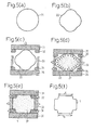
- Fig. 5(a) shows the cross section of a 590 MPa class material pipe 21 102mm in diameter and 2mm in wall thickness.
- the material pipe 21 is given concave curvatures, each of which is reverse to the convex curvature of a circle, by roll forming, and is formed into a pipe 22 having a shape shown in Fig. 5(b).
- the pipe 22 is formed by hydroforming as shown in Figs. 5(c) to 5(e). That is to say, the interior of the pipe 22 is filled with a liquid 37, and the pipe 22 is formed with a die assembly while applying a liquid pressure of about 5 MPa in the pipe 22 when the material pipe 21 is a 590 MPa class pipe having a wall thickness of 2mm. In this event, if there is no anxiety of buckling in the pressurized surfaces, the interior of the pipe may not be filled with the liquid 37.
- the pipe 22 is disposed in the hydroforming die assembly as shown in Fig. 5(c), and the assembly is compressed so as to narrow the distance between the upper die 31 and the lower die 35, thereby forming the pipe into the shape shown in Fig. 5(d).
- the material pipe is expanded as shown in Fig. 5(e) by increasing the liquid pressure while adding a compressive force to both ends of the material pipe.
- the movable upper dies 32 and the movable lower dies 34 are actuated to perform die clamping.
- a member having a shape shown in Fig. 5(f) is obtained.
- an initial liquid pressure of 10 to 15 MPa can be applied thereto, and a leak valve can be used to adjust the increase of the liquid pressure in the pipe accompanying the volume decrease caused by the die clamping.
- the liquid pressure in the pipe is controlled so as to increase with the increase of compressive force acting on the side wall portions and is increased up to about 40 MPa.
- the impact flexural strength of the strengthening members prepared in Examples 1 and 2 is evaluated.
- comparative materials the steel materials of the same strength as Examples are used, and the press-formed double-hat structures having the same basic rectangular cross sections and concave portions as Examples are employed.
- several kinds of materials varying the wall thickness are used for both Examples and the comparative examples.
- a test member 43 is cut out in the length of 300mm from a strengthening member 1, and steel materials acting as rigid bodies 42 are welded to both ends of the test member 43 to prepare a structure 900mm in length.
- the structure is supported by two supports 44 at an inter-support distance of 700mm and is subjected to an impact three-point bending test.
- the impact bending test is carried out under the condition that a striker 41 50mm in width is used and made collide with a top wall of the test member 43 at a collision speed of 8 m/s (Fig. 6).
- Fig. 7 The results of the test are shown in Fig. 7.
- the reference characters A, B, and H designate Example 1, Example 2, and the comparative example, respectively.
- the abscissas indicate the mass per unit length (kg/m) of the strengthening members.
- the ordinates indicate the average reactive force F ave (kN). It is found that the average reactive force of Example 1 (A) increases by 35% or more over the comparative example H on condition that the mass per unit length is identical.
- Example 2 (B) shows a better result than Example 1 (A).
- the ordinates indicate the energy absorption amount E ab . It is found that the energy absorption amount of Example 1 (A) increases by 18% or more over the comparative example H on condition that the mass per unit length is identical.
- Example 2 (B) shows a better result than Example 1 (A).
- a strengthening member according to the present invention not only provides an increase in energy absorption by axial impact crush but also provides an increase in strength and an increase in energy absorption by bending deformation.
- the energy absorption amount can be increased and flexural strength can be enhanced on condition that the mass per unit length of the member is not increased, by making the wall thickness of the corner concave portions thicker than that of the portions excluding the concave portions, or by making the hardness of the concave portions harder than that of the portions excluding the concave portions.
- the flexural strength can be far more enhanced by making the wall thickness of two sides facing each other in the cruciform thicker than the wall thickness of the other two sides facing each other.
- the above preferable wall thickness and hardness distributions can be easily obtained, and even if the wall thickness or hardness of the concave portions is equal to that of the portions excluding the concave portions, higher strength can be realized.
- a strengthening member for an automobile is formed of a high-strength steel sheet, by using drawing or hydroforming, a strengthening member not generating cracks can be produced.
Landscapes
- Engineering & Computer Science (AREA)
- Mechanical Engineering (AREA)
- Transportation (AREA)
- Chemical & Material Sciences (AREA)
- Combustion & Propulsion (AREA)
- Fluid Mechanics (AREA)
- Physics & Mathematics (AREA)
- General Engineering & Computer Science (AREA)
- Architecture (AREA)
- Structural Engineering (AREA)
- Shaping Metal By Deep-Drawing, Or The Like (AREA)
- Body Structure For Vehicles (AREA)
- Metal Extraction Processes (AREA)
Abstract
Description
Claims (6)
- A strengthening member for an automobile, being a lengthy strengthening member having concave portions at the four corners of a basic rectangular cross section and forming a cruciform closed section as a whole,
characterized in that the ratio (C/L) of the length (C) of said concave portions to the length (L) of the shorter sides of said basic rectangle is in the range from 0.05 to 0.45 and the strengthening member is formed by drawing or hydroforming. - A strengthening member for an automobile, being a lengthy strengthening member having concave portions at the four corners of a basic rectangular cross section and forming a cruciform closed section as a whole,
characterized in that the wall thickness of said concave portions is 5 to 30% thicker than the wall thickness of the portions excluding the concave portions, namely, the side walls and the top walls. - A strengthening member for an automobile, being a lengthy strengthening member having concave portions at the four corners of a basic rectangular cross section and forming a cruciform closed section as a whole,
characterized in that the hardness of said concave portions is 5% or more higher than the hardness of the portions excluding the concave portions, namely, the side walls and the top walls. - A strengthening member for an automobile according to claim 2 or 3, characterized by being formed by drawing.
- A strengthening member for an automobile according to claim 1, characterized in that the wall thickness of two sides facing each other in said cruciform closed section is 5 to 30% thicker than the wall thickness of the other two sides facing each other.
- A strengthening member for an automobile according to any one of claims 1 to 5, characterized in that the ratio (C/L) of the length (C) of said concave portions to the length (L) of the shorter sides of said basic rectangle is in the range from 0.2 to 0.35.
Applications Claiming Priority (3)
| Application Number | Priority Date | Filing Date | Title |
|---|---|---|---|
| JP2001089080A JP3854812B2 (en) | 2001-03-27 | 2001-03-27 | Strength members for automobiles |
| JP2001089080 | 2001-03-27 | ||
| PCT/JP2002/003015 WO2002076809A1 (en) | 2001-03-27 | 2002-03-27 | Automobile strengthening member |
Publications (3)
| Publication Number | Publication Date |
|---|---|
| EP1293415A1 true EP1293415A1 (en) | 2003-03-19 |
| EP1293415A4 EP1293415A4 (en) | 2010-03-03 |
| EP1293415B1 EP1293415B1 (en) | 2012-01-11 |
Family
ID=18944067
Family Applications (1)
| Application Number | Title | Priority Date | Filing Date |
|---|---|---|---|
| EP02708695A Expired - Lifetime EP1293415B1 (en) | 2001-03-27 | 2002-03-27 | Automobile frame member |
Country Status (4)
| Country | Link |
|---|---|
| US (1) | US6752451B2 (en) |
| EP (1) | EP1293415B1 (en) |
| JP (1) | JP3854812B2 (en) |
| WO (2) | WO2002076809A1 (en) |
Cited By (7)
| Publication number | Priority date | Publication date | Assignee | Title |
|---|---|---|---|---|
| WO2005097580A1 (en) * | 2004-03-30 | 2005-10-20 | Behr Gmbh & Co. Kg | Crossbeam or structural component for a motor vehicle |
| WO2006042032A3 (en) * | 2004-10-08 | 2006-08-31 | Noble Metal Proc Inc | Automotive crush tip and method of manufacturing |
| WO2006136405A1 (en) * | 2005-06-24 | 2006-12-28 | Gm Global Technology Operations, Inc. | Energy absorbing element and motor vehicle body using the same |
| WO2008031773A1 (en) * | 2006-09-13 | 2008-03-20 | Siemens Aktiengesellschaft | Expansion pipe |
| CN102164690A (en) * | 2008-09-25 | 2011-08-24 | 杰富意钢铁株式会社 | Method for forming deformed cross-section and formed article of quadrilateral cross-section exhibiting excellent spot weldability |
| CN103192879A (en) * | 2013-04-22 | 2013-07-10 | 刘九文 | Automobile beam processing method |
| WO2023001596A1 (en) * | 2021-07-19 | 2023-01-26 | Man Truck & Bus Se | Method for producing a frame component for a motor vehicle |
Families Citing this family (55)
| Publication number | Priority date | Publication date | Assignee | Title |
|---|---|---|---|---|
| US7043815B2 (en) | 2002-01-25 | 2006-05-16 | L & L Products, Inc. | Method for applying flowable materials |
| US7105112B2 (en) * | 2002-11-05 | 2006-09-12 | L&L Products, Inc. | Lightweight member for reinforcing, sealing or baffling |
| DE10323738B3 (en) * | 2003-05-24 | 2004-11-18 | Daimlerchrysler Ag | Manufacturing closed hollow profile involves cutting semi-finished product ends to form angled ends before squeezing; contour, angle are selected so ends form essentially flat shape after squeezing |
| EP1653114B2 (en) | 2003-07-28 | 2015-06-03 | Nippon Steel & Sumitomo Metal Corporation | Impact-absorbing member |
| DE602004027049D1 (en) | 2003-07-28 | 2010-06-17 | Sumitomo Metal Ind | IMPACT RECORD LINK |
| JP4819305B2 (en) * | 2003-09-04 | 2011-11-24 | 日産自動車株式会社 | Method for manufacturing reinforcing member |
| JP4388340B2 (en) * | 2003-10-03 | 2009-12-24 | 新日本製鐵株式会社 | Strength members for automobiles |
| US7180027B2 (en) * | 2004-03-31 | 2007-02-20 | L & L Products, Inc. | Method of applying activatable material to a member |
| US20060021697A1 (en) * | 2004-07-30 | 2006-02-02 | L&L Products, Inc. | Member for reinforcing, sealing or baffling and reinforcement system formed therewith |
| US20060090343A1 (en) * | 2004-10-28 | 2006-05-04 | L&L Products, Inc. | Member for reinforcing, sealing or baffling and reinforcement system formed therewith |
| FR2884214B1 (en) * | 2005-04-07 | 2007-07-06 | Faurecia Bloc Avant | STRUCTURAL ELEMENT FOR A MOTOR VEHICLE, CORRESPONDING MOTOR VEHICLE, AND METHOD FOR MANUFACTURING SUCH A STRUCTURAL ELEMENT. |
| US20060237976A1 (en) * | 2005-04-20 | 2006-10-26 | Shape Corporation | Crushable structure manufactured from mechanical expansion |
| WO2007029362A1 (en) * | 2005-09-09 | 2007-03-15 | Toyoda Iron Works Co., Ltd | Impact absorption member for vehicle |
| US20070283562A1 (en) * | 2006-06-05 | 2007-12-13 | Benteler Automotive Corporation | Method for making a non-driving vehicle axle beam |
| US7441819B2 (en) * | 2006-09-26 | 2008-10-28 | Ford Global Technologies, Llc | Tubular structural joint for automotive front end |
| US20080098601A1 (en) * | 2006-10-30 | 2008-05-01 | Shape Corporation | Tubular tapered crushable structures and manufacturing methods |
| JP5040568B2 (en) * | 2007-10-01 | 2012-10-03 | マツダ株式会社 | Auto body structure |
| JP5167823B2 (en) * | 2008-01-15 | 2013-03-21 | トヨタ自動車株式会社 | Shock absorbing member |
| JP5245674B2 (en) * | 2008-09-19 | 2013-07-24 | マツダ株式会社 | Body structure |
| US8641129B2 (en) * | 2008-09-19 | 2014-02-04 | Ford Global Technologies, Llc | Twelve-cornered strengthening member |
| US9533710B2 (en) * | 2008-09-19 | 2017-01-03 | Ford Global Technologies, Llc | Twelve-cornered strengthening member |
| US8539737B2 (en) | 2008-09-19 | 2013-09-24 | Ford Global Technologies, Llc | Twelve-cornered strengthening member |
| US9187127B2 (en) | 2008-09-19 | 2015-11-17 | Ford Global Technologies, Llc | Twelve-cornered strengthening member, assemblies including a twelve-cornered strengthening member, and methods of manufacturing and joining the same |
| JP5316935B2 (en) * | 2008-09-26 | 2013-10-16 | 新日鐵住金株式会社 | Steel pipe for impact energy absorption for automobile and method for manufacturing the same |
| JP5609322B2 (en) * | 2010-06-30 | 2014-10-22 | 日産自動車株式会社 | Method for manufacturing tube member |
| ES2387143B1 (en) * | 2010-10-21 | 2013-04-15 | Europea De Construcciones Metalicas, S.A. | "DIRECT CONNECTION BETWEEN A TUBE AND A FLAT ELEMENT" |
| US8459726B2 (en) | 2011-04-15 | 2013-06-11 | Ford Global Technologies, Llc. | Multi-cornered strengthening members |
| US8505349B2 (en) * | 2011-05-11 | 2013-08-13 | Ford Global Technologies, Llc | Method and apparatus for hydro-forming an elongated tubular member |
| JP2013067324A (en) * | 2011-09-26 | 2013-04-18 | Aisin Seiki Co Ltd | Crash box and vehicle bumper apparatus including the same |
| US8443642B2 (en) * | 2011-10-20 | 2013-05-21 | Ford Global Technologies, Llc | Process for pre-forming cylindrical tubes into tubular members having sharp corners |
| JP5837472B2 (en) * | 2012-10-02 | 2015-12-24 | 株式会社神戸製鋼所 | Electromagnetic tube expansion method for rectangular cross-section members |
| GB201207481D0 (en) | 2012-04-26 | 2012-06-13 | Zephyros Inc | Applying flowable materials to synthetic substrates |
| BR112015003445A2 (en) | 2012-08-21 | 2017-07-04 | Nippon Steel & Sumitomo Metal Corp | crash box and car chassis |
| WO2014073083A1 (en) * | 2012-11-08 | 2014-05-15 | Jfeスチール株式会社 | Impact absorbing member |
| EP3031674B1 (en) * | 2014-12-03 | 2018-01-10 | Ford Global Technologies, LLC | A twelve-cornered strengthening member, assemblies including a twelve-cornered strengthening member, and methods of manufacturing and joining the same |
| JP6449104B2 (en) * | 2015-06-02 | 2019-01-09 | 住友重機械工業株式会社 | Molding equipment |
| WO2016199979A1 (en) * | 2015-06-09 | 2016-12-15 | 한국항공우주연구원 | Corrugated buffering member having variable thickness and method for molding same |
| US10315698B2 (en) | 2015-06-24 | 2019-06-11 | Ford Global Technologies, Llc | Sixteen-cornered strengthening member for vehicles |
| US9944323B2 (en) | 2015-10-27 | 2018-04-17 | Ford Global Technologies, Llc | Twenty-four-cornered strengthening member for vehicles |
| US9889887B2 (en) | 2016-01-20 | 2018-02-13 | Ford Global Technologies, Llc | Twelve-cornered strengthening member for a vehicle with straight and curved sides and an optimized straight side length to curved side radius ratio |
| US9789906B1 (en) | 2016-03-23 | 2017-10-17 | Ford Global Technologies, Llc | Twenty-eight-cornered strengthening member for vehicles |
| US10704638B2 (en) | 2016-04-26 | 2020-07-07 | Ford Global Technologies, Llc | Cellular structures with twelve-cornered cells |
| US10393315B2 (en) | 2016-04-26 | 2019-08-27 | Ford Global Technologies, Llc | Cellular structures with twelve-cornered cells |
| US10473177B2 (en) | 2016-08-23 | 2019-11-12 | Ford Global Technologies, Llc | Cellular structures with sixteen-cornered cells |
| US10220881B2 (en) | 2016-08-26 | 2019-03-05 | Ford Global Technologies, Llc | Cellular structures with fourteen-cornered cells |
| US10300947B2 (en) | 2016-08-30 | 2019-05-28 | Ford Global Technologies, Llc | Twenty-eight-cornered strengthening member for vehicles |
| US10279842B2 (en) | 2016-08-30 | 2019-05-07 | Ford Global Technologies, Llc | Twenty-eight-cornered strengthening member for vehicles |
| US10429006B2 (en) | 2016-10-12 | 2019-10-01 | Ford Global Technologies, Llc | Cellular structures with twelve-cornered cells |
| CN107855398B (en) * | 2017-11-06 | 2019-09-10 | 北京航星机器制造有限公司 | A kind of manufacturing process improving superplastic forming special-shaped barrel Thickness Distribution by pre- reversible deformation |
| EP3486146B1 (en) * | 2017-11-15 | 2021-04-14 | Sika Technology Ag | Device for reinforcing and sealing a structural element |
| US10562478B2 (en) * | 2018-02-23 | 2020-02-18 | Ford Global Technologies, Llc | Strengthening structure of a vehicle |
| US10829070B2 (en) | 2018-02-23 | 2020-11-10 | Ford Global Technologies, Llc | Strengthening structure of a vehicle |
| US11292522B2 (en) | 2019-12-04 | 2022-04-05 | Ford Global Technologies, Llc | Splayed front horns for vehicle frames |
| JP7286571B2 (en) * | 2020-03-02 | 2023-06-05 | 住友重機械工業株式会社 | Molding apparatus and molding method |
| KR20230048624A (en) | 2020-08-11 | 2023-04-11 | 스미도모쥬기가이고교 가부시키가이샤 | Molding device, and metal pipe |
Family Cites Families (15)
| Publication number | Priority date | Publication date | Assignee | Title |
|---|---|---|---|---|
| US2205893A (en) * | 1937-09-03 | 1940-06-25 | Gen Electric | Method of corrugating a heatradiating tube |
| US3209432A (en) * | 1963-12-23 | 1965-10-05 | Ford Motor Co | Method for fabricating a structural member |
| US4829803A (en) * | 1987-05-06 | 1989-05-16 | Ti Corporate Services Limited | Method of forming box-like frame members |
| US4981005A (en) * | 1989-09-11 | 1991-01-01 | Mcginnis Henry J | Tapered pole and method of making |
| JPH05293535A (en) * | 1992-04-20 | 1993-11-09 | Furukawa Alum Co Ltd | Production of reinforcing member for instrumental panel |
| US5794398A (en) * | 1992-08-25 | 1998-08-18 | Kaehler; Klaus | Framework with hollow members process for producing the same and its use |
| DE69403722T2 (en) * | 1993-04-19 | 1997-09-25 | Gen Motors Corp | Process for forming a tubular element |
| JPH08337183A (en) * | 1995-06-13 | 1996-12-24 | Nissan Motor Co Ltd | Strength member structure |
| US5557961A (en) * | 1995-11-13 | 1996-09-24 | General Motors Corporation | Hydroformed structural member with varied wall thickness |
| JP2990057B2 (en) * | 1996-03-13 | 1999-12-13 | アイシン軽金属株式会社 | Energy absorption structure on the side of the vehicle |
| GB2332163B (en) * | 1997-12-13 | 2002-03-13 | Gkn Sankey Ltd | A hydroforming process |
| JPH11235986A (en) * | 1998-02-20 | 1999-08-31 | Toyota Motor Corp | Vehicle side member and method of manufacturing the same |
| JP3642232B2 (en) * | 1999-06-29 | 2005-04-27 | 日産自動車株式会社 | Fluid pressure molding method, fluid pressure molding apparatus, and body member |
| JP3687838B2 (en) * | 1999-03-26 | 2005-08-24 | 日産自動車株式会社 | Fluid pressure molding method, fluid pressure mold and fluid pressure molded member |
| US6609301B1 (en) * | 1999-09-08 | 2003-08-26 | Magna International Inc. | Reinforced hydroformed members and methods of making the same |
-
2001
- 2001-03-27 JP JP2001089080A patent/JP3854812B2/en not_active Expired - Fee Related
-
2002
- 2002-03-27 WO PCT/JP2002/003015 patent/WO2002076809A1/en not_active Ceased
- 2002-03-27 EP EP02708695A patent/EP1293415B1/en not_active Expired - Lifetime
- 2002-03-27 US US10/311,518 patent/US6752451B2/en not_active Expired - Fee Related
- 2002-03-27 WO PCT/JP2002/003016 patent/WO2002076810A1/en not_active Ceased
Cited By (11)
| Publication number | Priority date | Publication date | Assignee | Title |
|---|---|---|---|---|
| WO2005097580A1 (en) * | 2004-03-30 | 2005-10-20 | Behr Gmbh & Co. Kg | Crossbeam or structural component for a motor vehicle |
| WO2006042032A3 (en) * | 2004-10-08 | 2006-08-31 | Noble Metal Proc Inc | Automotive crush tip and method of manufacturing |
| WO2006136405A1 (en) * | 2005-06-24 | 2006-12-28 | Gm Global Technology Operations, Inc. | Energy absorbing element and motor vehicle body using the same |
| US7926868B2 (en) | 2005-06-24 | 2011-04-19 | GM Global Technology Operations LLC | Energy absorbing element and motor vehicle body using the same |
| US8177269B2 (en) | 2005-06-24 | 2012-05-15 | GM Global Technology Operations LLC | Energy absorbing element and motor vehicle body using the same |
| WO2008031773A1 (en) * | 2006-09-13 | 2008-03-20 | Siemens Aktiengesellschaft | Expansion pipe |
| CN102164690A (en) * | 2008-09-25 | 2011-08-24 | 杰富意钢铁株式会社 | Method for forming deformed cross-section and formed article of quadrilateral cross-section exhibiting excellent spot weldability |
| EP2351623A4 (en) * | 2008-09-25 | 2012-10-31 | Jfe Steel Corp | IRREGULAR CROSS SECTION SECTION SHAPING METHOD AND MOLDED ARTICLE HAVING PARALLELOGRAM CROSS SECTION AND HAVING EXCELLENT POINT SOLDER WELDING PROPERTIES |
| CN103192879A (en) * | 2013-04-22 | 2013-07-10 | 刘九文 | Automobile beam processing method |
| CN103192879B (en) * | 2013-04-22 | 2016-01-13 | 刘九文 | A kind of job operation of car beam |
| WO2023001596A1 (en) * | 2021-07-19 | 2023-01-26 | Man Truck & Bus Se | Method for producing a frame component for a motor vehicle |
Also Published As
| Publication number | Publication date |
|---|---|
| US6752451B2 (en) | 2004-06-22 |
| JP3854812B2 (en) | 2006-12-06 |
| WO2002076810A1 (en) | 2002-10-03 |
| WO2002076809A1 (en) | 2002-10-03 |
| US20030151273A1 (en) | 2003-08-14 |
| JP2002284033A (en) | 2002-10-03 |
| EP1293415B1 (en) | 2012-01-11 |
| EP1293415A4 (en) | 2010-03-03 |
Similar Documents
| Publication | Publication Date | Title |
|---|---|---|
| US6752451B2 (en) | Strengthening member for automobile | |
| US7617916B2 (en) | Tapered crushable polygonal structure | |
| KR101821074B1 (en) | Production method for press-molded body, and press molding device | |
| CN100476233C (en) | Cash energy absorption member | |
| JP3864899B2 (en) | Press working method with excellent shape freezing property and processing tool used therefor | |
| JP7115558B2 (en) | skeleton member | |
| KR101947938B1 (en) | Structural member | |
| KR20120138785A (en) | Vehicle component | |
| US20030131646A1 (en) | Component with locally limmited reinforcement regions and method for production thereof | |
| US7695824B2 (en) | Reinforced member | |
| JPWO2017217538A1 (en) | Spheroid for automobile structural member, method for manufacturing squeeze for automobile structural member, and apparatus for manufacturing sinter for automobile structural member | |
| JP4039032B2 (en) | Impact energy absorbing member | |
| JPH08128487A (en) | Energy absorbing material and manufacturing method thereof | |
| JP2003225714A (en) | Metal tube forming method and collision energy absorbing member | |
| JP4078516B2 (en) | Collision energy absorbing member and automobile side member using the same | |
| KR20250103709A (en) | Absence of skeleton | |
| JP4582630B2 (en) | Press molding method for structural members with excellent shock absorption characteristics | |
| JP2001009529A (en) | Hydraulic molding method, hydraulic molding apparatus and vehicle body member | |
| KR20200126580A (en) | Seat cross member roll forming manufacturing method for vehicles | |
| JP4759871B2 (en) | Impact energy absorbing member | |
| JP2021187433A (en) | Automobile structural component, and method for manufacture thereof | |
| JP7857508B1 (en) | Impact absorbing member and method for manufacturing the same | |
| JP7568980B2 (en) | Frame material | |
| JP4388461B2 (en) | Strength member for automobile having excellent collision characteristics and structural member for automobile using the same | |
| JP4734129B2 (en) | Automotive strength members with excellent impact characteristics |
Legal Events
| Date | Code | Title | Description |
|---|---|---|---|
| PUAI | Public reference made under article 153(3) epc to a published international application that has entered the european phase |
Free format text: ORIGINAL CODE: 0009012 |
|
| 17P | Request for examination filed |
Effective date: 20030115 |
|
| AK | Designated contracting states |
Designated state(s): AT BE CH CY DE DK ES FI FR GB GR IE IT LI LU MC NL PT SE TR Kind code of ref document: A1 Designated state(s): AT BE CH CY DE DK ES FI FR GB GR IE IT LI LU MC NL PT SE TR |
|
| A4 | Supplementary search report drawn up and despatched |
Effective date: 20100129 |
|
| 17Q | First examination report despatched |
Effective date: 20100512 |
|
| REG | Reference to a national code |
Ref country code: DE Ref legal event code: R079 Ref document number: 60241951 Country of ref document: DE Free format text: PREVIOUS MAIN CLASS: B62D0021150000 Ipc: B62D0029000000 |
|
| RIC1 | Information provided on ipc code assigned before grant |
Ipc: B62D 29/00 20060101AFI20110414BHEP |
|
| RTI1 | Title (correction) |
Free format text: AUTOMOBILE FRAME MEMBER |
|
| GRAP | Despatch of communication of intention to grant a patent |
Free format text: ORIGINAL CODE: EPIDOSNIGR1 |
|
| RIN1 | Information on inventor provided before grant (corrected) |
Inventor name: SAKURAI, HIROSHI Inventor name: TERADA, YOSHIONIPPON STEEL CORPORATION KIMITSU WOR Inventor name: SUMIMOTO,DAIGONIPPON STEEL CORPORATION KIMITSU WOR Inventor name: KURIYAMA,YUKIHISANIPPON STEEL CORPORATION TECHNICA Inventor name: SAKAMOTO,SHINYANIPPON STEEL CORPORATION KIMITSU WO Inventor name: NAKANISHI, EIZABUROU |
|
| GRAS | Grant fee paid |
Free format text: ORIGINAL CODE: EPIDOSNIGR3 |
|
| GRAA | (expected) grant |
Free format text: ORIGINAL CODE: 0009210 |
|
| AK | Designated contracting states |
Kind code of ref document: B1 Designated state(s): DE FR GB |
|
| REG | Reference to a national code |
Ref country code: GB Ref legal event code: FG4D |
|
| REG | Reference to a national code |
Ref country code: DE Ref legal event code: R096 Ref document number: 60241951 Country of ref document: DE Effective date: 20120308 |
|
| PGFP | Annual fee paid to national office [announced via postgrant information from national office to epo] |
Ref country code: GB Payment date: 20120302 Year of fee payment: 11 |
|
| PGFP | Annual fee paid to national office [announced via postgrant information from national office to epo] |
Ref country code: DE Payment date: 20120430 Year of fee payment: 11 |
|
| PGFP | Annual fee paid to national office [announced via postgrant information from national office to epo] |
Ref country code: FR Payment date: 20120416 Year of fee payment: 11 |
|
| PLBE | No opposition filed within time limit |
Free format text: ORIGINAL CODE: 0009261 |
|
| STAA | Information on the status of an ep patent application or granted ep patent |
Free format text: STATUS: NO OPPOSITION FILED WITHIN TIME LIMIT |
|
| 26N | No opposition filed |
Effective date: 20121012 |
|
| REG | Reference to a national code |
Ref country code: DE Ref legal event code: R097 Ref document number: 60241951 Country of ref document: DE Effective date: 20121012 |
|
| REG | Reference to a national code |
Ref country code: DE Ref legal event code: R082 Ref document number: 60241951 Country of ref document: DE Representative=s name: VOSSIUS & PARTNER, DE |
|
| REG | Reference to a national code |
Ref country code: DE Ref legal event code: R081 Ref document number: 60241951 Country of ref document: DE Owner name: NIPPON STEEL & SUMITOMO METAL CORPORATION, JP Free format text: FORMER OWNER: NIPPON STEEL CORP., NISSAN MOTOR CO., LTD., , JP Effective date: 20130422 Ref country code: DE Ref legal event code: R081 Ref document number: 60241951 Country of ref document: DE Owner name: NISSAN MOTOR CO., LTD., JP Free format text: FORMER OWNER: NIPPON STEEL CORP., NISSAN MOTOR CO., LTD., , JP Effective date: 20130422 Ref country code: DE Ref legal event code: R081 Ref document number: 60241951 Country of ref document: DE Owner name: NIPPON STEEL & SUMITOMO METAL CORPORATION, JP Free format text: FORMER OWNER: NIPPON STEEL CORP., NISSAN MOTOR CO., LTD., , JP Effective date: 20120118 Ref country code: DE Ref legal event code: R081 Ref document number: 60241951 Country of ref document: DE Owner name: NISSAN MOTOR CO., LTD., JP Free format text: FORMER OWNER: NIPPON STEEL CORP., NISSAN MOTOR CO., LTD., , JP Effective date: 20120118 Ref country code: DE Ref legal event code: R082 Ref document number: 60241951 Country of ref document: DE Representative=s name: VOSSIUS & PARTNER, DE Effective date: 20130422 Ref country code: DE Ref legal event code: R081 Ref document number: 60241951 Country of ref document: DE Owner name: NISSAN MOTOR CO., LTD., YOKOHAMA-SHI, JP Free format text: FORMER OWNERS: NIPPON STEEL CORP., TOKIO/TOKYO, JP; NISSAN MOTOR CO., LTD., YOKOHAMA-SHI, KANAGAWA-KEN, JP Effective date: 20130422 Ref country code: DE Ref legal event code: R082 Ref document number: 60241951 Country of ref document: DE Representative=s name: VOSSIUS & PARTNER PATENTANWAELTE RECHTSANWAELT, DE Effective date: 20130422 Ref country code: DE Ref legal event code: R081 Ref document number: 60241951 Country of ref document: DE Owner name: NIPPON STEEL & SUMITOMO METAL CORPORATION, JP Free format text: FORMER OWNERS: NIPPON STEEL CORP., TOKIO/TOKYO, JP; NISSAN MOTOR CO., LTD., YOKOHAMA-SHI, KANAGAWA-KEN, JP Effective date: 20130422 Ref country code: DE Ref legal event code: R081 Ref document number: 60241951 Country of ref document: DE Owner name: NIPPON STEEL & SUMITOMO METAL CORPORATION, JP Free format text: FORMER OWNERS: NIPPON STEEL CORP., TOKIO/TOKYO, JP; NISSAN MOTOR CO., LTD., YOKOHAMA-SHI, KANAGAWA-KEN, JP Effective date: 20120118 Ref country code: DE Ref legal event code: R081 Ref document number: 60241951 Country of ref document: DE Owner name: NISSAN MOTOR CO., LTD., YOKOHAMA-SHI, JP Free format text: FORMER OWNERS: NIPPON STEEL CORP., TOKIO/TOKYO, JP; NISSAN MOTOR CO., LTD., YOKOHAMA-SHI, KANAGAWA-KEN, JP Effective date: 20120118 |
|
| GBPC | Gb: european patent ceased through non-payment of renewal fee |
Effective date: 20130327 |
|
| REG | Reference to a national code |
Ref country code: FR Ref legal event code: CD Owner name: NISSAN MOTOR COMPANY LIMITED, JP Effective date: 20130913 Ref country code: FR Ref legal event code: CA Effective date: 20130913 Ref country code: FR Ref legal event code: CD Owner name: NIPPON STEEL & SUMITOMO METAL CORPORATION, JP Effective date: 20130913 |
|
| REG | Reference to a national code |
Ref country code: FR Ref legal event code: ST Effective date: 20131129 |
|
| REG | Reference to a national code |
Ref country code: DE Ref legal event code: R119 Ref document number: 60241951 Country of ref document: DE Effective date: 20131001 |
|
| PG25 | Lapsed in a contracting state [announced via postgrant information from national office to epo] |
Ref country code: DE Free format text: LAPSE BECAUSE OF NON-PAYMENT OF DUE FEES Effective date: 20131001 Ref country code: FR Free format text: LAPSE BECAUSE OF NON-PAYMENT OF DUE FEES Effective date: 20130402 Ref country code: GB Free format text: LAPSE BECAUSE OF NON-PAYMENT OF DUE FEES Effective date: 20130327 |