EP1293406A2 - Bremsdruckregelungsverfahren - Google Patents
Bremsdruckregelungsverfahren Download PDFInfo
- Publication number
- EP1293406A2 EP1293406A2 EP02016829A EP02016829A EP1293406A2 EP 1293406 A2 EP1293406 A2 EP 1293406A2 EP 02016829 A EP02016829 A EP 02016829A EP 02016829 A EP02016829 A EP 02016829A EP 1293406 A2 EP1293406 A2 EP 1293406A2
- Authority
- EP
- European Patent Office
- Prior art keywords
- braking
- demand
- brake
- vehicle
- delay
- Prior art date
- Legal status (The legal status is an assumption and is not a legal conclusion. Google has not performed a legal analysis and makes no representation as to the accuracy of the status listed.)
- Granted
Links
- 238000000034 method Methods 0.000 title claims description 56
- 230000001105 regulatory effect Effects 0.000 claims abstract description 11
- 230000007423 decrease Effects 0.000 claims abstract description 4
- 230000008569 process Effects 0.000 claims description 24
- 239000000654 additive Substances 0.000 claims description 5
- 230000000996 additive effect Effects 0.000 claims description 5
- 230000010354 integration Effects 0.000 claims description 3
- 230000002123 temporal effect Effects 0.000 claims description 3
- 230000033228 biological regulation Effects 0.000 claims description 2
- 230000001276 controlling effect Effects 0.000 claims description 2
- 238000010586 diagram Methods 0.000 description 6
- 230000001133 acceleration Effects 0.000 description 5
- 238000011161 development Methods 0.000 description 5
- 230000018109 developmental process Effects 0.000 description 5
- 230000003247 decreasing effect Effects 0.000 description 4
- 230000001419 dependent effect Effects 0.000 description 4
- 230000004048 modification Effects 0.000 description 4
- 238000012986 modification Methods 0.000 description 4
- 230000009467 reduction Effects 0.000 description 4
- 230000008859 change Effects 0.000 description 3
- 239000000725 suspension Substances 0.000 description 3
- 229910000831 Steel Inorganic materials 0.000 description 2
- 230000004069 differentiation Effects 0.000 description 2
- 238000011156 evaluation Methods 0.000 description 2
- 239000010959 steel Substances 0.000 description 2
- 230000007704 transition Effects 0.000 description 2
- 230000006978 adaptation Effects 0.000 description 1
- 238000006243 chemical reaction Methods 0.000 description 1
- 238000011217 control strategy Methods 0.000 description 1
- 230000001934 delay Effects 0.000 description 1
- 230000000994 depressogenic effect Effects 0.000 description 1
- 238000009434 installation Methods 0.000 description 1
Images



Classifications
-
- B—PERFORMING OPERATIONS; TRANSPORTING
- B60—VEHICLES IN GENERAL
- B60T—VEHICLE BRAKE CONTROL SYSTEMS OR PARTS THEREOF; BRAKE CONTROL SYSTEMS OR PARTS THEREOF, IN GENERAL; ARRANGEMENT OF BRAKING ELEMENTS ON VEHICLES IN GENERAL; PORTABLE DEVICES FOR PREVENTING UNWANTED MOVEMENT OF VEHICLES; VEHICLE MODIFICATIONS TO FACILITATE COOLING OF BRAKES
- B60T8/00—Arrangements for adjusting wheel-braking force to meet varying vehicular or ground-surface conditions, e.g. limiting or varying distribution of braking force
- B60T8/24—Arrangements for adjusting wheel-braking force to meet varying vehicular or ground-surface conditions, e.g. limiting or varying distribution of braking force responsive to vehicle inclination or change of direction, e.g. negotiating bends
- B60T8/245—Longitudinal vehicle inclination
-
- B—PERFORMING OPERATIONS; TRANSPORTING
- B60—VEHICLES IN GENERAL
- B60T—VEHICLE BRAKE CONTROL SYSTEMS OR PARTS THEREOF; BRAKE CONTROL SYSTEMS OR PARTS THEREOF, IN GENERAL; ARRANGEMENT OF BRAKING ELEMENTS ON VEHICLES IN GENERAL; PORTABLE DEVICES FOR PREVENTING UNWANTED MOVEMENT OF VEHICLES; VEHICLE MODIFICATIONS TO FACILITATE COOLING OF BRAKES
- B60T8/00—Arrangements for adjusting wheel-braking force to meet varying vehicular or ground-surface conditions, e.g. limiting or varying distribution of braking force
- B60T8/17—Using electrical or electronic regulation means to control braking
- B60T8/172—Determining control parameters used in the regulation, e.g. by calculations involving measured or detected parameters
-
- B—PERFORMING OPERATIONS; TRANSPORTING
- B60—VEHICLES IN GENERAL
- B60T—VEHICLE BRAKE CONTROL SYSTEMS OR PARTS THEREOF; BRAKE CONTROL SYSTEMS OR PARTS THEREOF, IN GENERAL; ARRANGEMENT OF BRAKING ELEMENTS ON VEHICLES IN GENERAL; PORTABLE DEVICES FOR PREVENTING UNWANTED MOVEMENT OF VEHICLES; VEHICLE MODIFICATIONS TO FACILITATE COOLING OF BRAKES
- B60T8/00—Arrangements for adjusting wheel-braking force to meet varying vehicular or ground-surface conditions, e.g. limiting or varying distribution of braking force
- B60T8/24—Arrangements for adjusting wheel-braking force to meet varying vehicular or ground-surface conditions, e.g. limiting or varying distribution of braking force responsive to vehicle inclination or change of direction, e.g. negotiating bends
Definitions
- the present invention relates to a method of control the brake pressure of a vehicle according to the preamble of Claim 1.
- Such a method is known from DE 44 43 522 A1.
- the inclination i. the slope or the slope of Lane determined.
- a pressure base value that is at a brake application by the driver to from the position of the brake pedal resulting pressure setpoint is added.
- the print base value is negative on a slope and positive on a gradient.
- the Add the pressure base value to that given by the driver Brake pressure setpoint always occurs when a downgrade is driven. If the pressure base value even at a slope added to the pressure setpoint reaches the vehicle regardless of the lane, always the same delay based on the brake pedal deflection. So the driver can over the brake pedal set a delay.
- Load sensors are either in load sensing valves integrate or deliver their signals to one central control unit, which has a brake pressure proportional to the Load signals calculated.
- load signals are not available on every vehicle, especially not on vehicles with a steel suspension, but usually only at Trucks with air suspension. For vehicles with one Steel suspension is therefore the installation of an additional Sensors required.
- Such a “settlement” is desirable when it comes through the Loading condition of the vehicle is caused.
- a compensation but is not desirable if the deviation on "outer Driving resistance forces ", such as on a changing Road gradient, based. Compensate in simple terms the o.g. Process the road grade gradient by entering an additional braking force. The regulation thus leads to a Mountain braking to a stronger braking force than one Mountain braking at the same brake pedal position. This is for the driver is unfamiliar and can cause false reactions of the driver to lead.
- the object of the invention is an alternative control method to give the driver a more "natural" brake when braking Driving feeling conveys, similar to a conventional one Braking system.
- the basic principle of the invention is to change a driving resistance, in particular a change in the road gradient at least during a portion of a braking process only then to compensate by modifying the brake pressure, when the driving resistance or the road gradient changes.
- the control strategy according to the invention improves the "brake pedal feeling" of the driver, which causes the Driving safety increased. Nevertheless, this regulatory procedure is also valid reliable and robust, which explains in more detail becomes.
- the driver over the brake pedal predetermined brake request signal during the Braking or at least during a subsection of the Brake process only modified when the Driving resistance reduced during braking.
- the brake demand signal is not modified.
- a predetermined by the brake pedal "delay request" is overbrake. This then causes the driver, on his own to withdraw the braking force.
- the method is technically robust, since a deceleration decrease, i.e. an acceleration increase on a downhill with increasing gradient by a control intervention is compensated.
- a deceleration decrease i.e. an acceleration increase on a downhill with increasing gradient by a control intervention is compensated.
- the driver On level ground as well as on roads with constant slope or constant slope and at roads with decreasing slope, the driver has in the essentially the same driving feel as a conventional one Braking system.
- a deviating driving feeling arises only in Trap an increasing "gradient", for example when driving down a lane during a downhill run Braking.
- a braking operation control technology in a first brake section and a divided second brake section, which a different Control algorithm is based.
- the second braking section is between an overbraking and a Unterbremsung the vehicle with respect to the of Driver specified unmodified braking request signal distinguished.
- overbraking e.g. as a result of a during the braking process increasing road gradient, takes place no braking intervention.
- a control intervention i. a modification the brake request signal is, however, when a Under braking threatens, which is the case, for example, if the slope of the roadway increases during the braking process.
- the current "driving resistance-related Deceleration of the vehicle is in particular by the slope or the slope of the Road surface, caused by wind forces, friction losses, etc.
- the slope or the slope of the Road surface caused by wind forces, friction losses, etc.
- US 5,549,364 and DE 44 12 430 C1 described the slope and one of the Slope assigned road resistance or a "vehicle deceleration" determined.
- driving uphill is this vehicle deceleration positive and on a downhill negative, i. Due to the gradient acts on the vehicle an acceleration force.
- the brake request signal even then be modified if the driving resistance delay is constant, which will be explained later.
- step 2 checks whether there is a braking demand signal is present, ie, the brake pedal if the driver and a certain "target deceleration" z demand dictates.
- the driving resistance or a delay z FW associated with the driving resistance is determined in step 3.
- the gradient or the gradient of the road is determined.
- the slope or the slope are referred to in the following simplified as "slope”.
- the deceleration or acceleration z FW is determined according to the slope.
- a travel variable s is set to zero.
- the travel variable s describes the distance traveled since the last determination of the travel resistance-related deceleration, which is measured by means of wheel speed sensors.
- the vehicle deceleration z wheel is determined, by differentiation of one or more wheel speed signals, which is indicated by the block 6.
- a delay difference ⁇ z is then calculated from the feedback signal Z feedback by subtracting the desired deceleration z demand associated with the brake request signal.
- the drag-related delay z FW thus enters the delay difference ⁇ z via z feedback since the service brakes of the vehicle are basically not intended to compensate for the "slope gradient" of the vehicle deceleration in order to give the driver a "more natural” brake pedal feel.
- the delay deviation ⁇ z may also be referred to as an error signal become.
- step 9 the distance s (t) traveled since the last determination or estimation of the travel-related deceleration z FW is determined by summing the distance s traveled since the last estimate of the travel-related deceleration z FW until the start of braking and since the start of braking distance traveled, which is calculated by temporal integration of the vehicle speed determined by wheel speed sensors.
- step 10 a case distinction is then made, wherein it is checked whether the path s (t) is smaller or larger than a predetermined path constant C 0 .
- the case s ⁇ C 0 corresponds to the initial phase of the braking process and the case s> 0 C a subsequent to the initial phase of the second braking phase.
- step 4 the path s in step 4 is unbraked Ride initialized.
- Step 10 may include other criteria for differentiation between an initial braking phase and an advanced one Braking phase can be used. For example, based on the since Brake start elapsed time between the initial braking phase and the advanced braking phase.
- the delay difference ⁇ z in this case ie in the initial phase is certainly not caused by a change in the slope gradient. Rather, it can be assumed that the delay difference ⁇ z is caused by uncertainties or faulty vehicle-dependent parameters, such as vehicle mass or braking factor.
- the delay difference ⁇ z is compensated by a factor K 1 in the initial phase of the braking process.
- K 2 0 applies.
- the steps 11-13 are possibly repeated several times, in which case both a positive or negative modification of the brake request signal, ie a brake pressure increase and a brake pressure reduction is possible.
- step 14 it is checked if the delay difference ⁇ z ⁇ 0 is. If ⁇ z> 0, it is in relation to that of the driver predetermined unmodified brake request signal a Braking ago, consciously in accordance with the invention in purchase is taken. In this case, no control intervention takes place.
- K 2 K 2 - C 2 ⁇ ⁇ z, where C 2 is a predetermined constant.
- a minimum selection is then made between the previously determined additive element K 2 and a value C 3 ⁇ z demand , where C 3 is a predetermined constant.
- K 2 is set equal to the minimum of these two values.
- the additive element K 2 initialized in step 12 is therefore calculated iteratively in step 15 and is limited according to step 16 by the brake pedal signal z demand , which improves the braking comfort.
- step 13 the brake pressure p demand is calculated.
- the output value is set to zero in the case where there is no brake request signal in step 5.
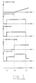
- a downhill is shown at constant slope.
- the brake pedal is depressed and until held at time t2, resulting in a corresponding Set rectangular brake pressure curve. According to that Slope of the road, the road slope is negative.
- the braking behavior according to the invention in a downhill with constant gradient thus corresponds to that of a conventional one Vehicle.
- Fig. 3 describes a vehicle which initially, i. until the Time t2 drives on a flat road. From the moment t2 climbs the road.
- the diagram of the brake pedal position and the brake pressure curve corresponds to that of FIG. 1.
- the road gradient diagram has a rectangular course.
- the delay time diagram it can be seen that that the vehicle is unbraked until time t1.
- the driver depresses the brake pedal, causing himself a positive delay, i. a deceleration of the vehicle established.
- the delay comes through the Service brake system an additional slope-related Delay force added, reducing the delay of the vehicle rises again.
- the vehicle is ready braked that the driver is off the brake pedal, causing the Vehicle deceleration drops by the "service brake share". From the Time t3, the vehicle is thus only by the "Road gradient component" braked.
- the braking behavior corresponds of the vehicle that of a conventional vehicle.
- Fig. 4 describes the vehicle movement from the plane into a Track with a constant gradient. Analogous to FIGS. 2, 3 the driver presses the brake pedal at time t1 and releases the Brake at time t3. According to the road, the Road gradient from time t2 a negative value.
- Characteristic of the invention is the brake pressure curve and the delay curve, which is shown here only qualitatively is, of an exact representation or distinction of the both brake sections (initial braking phase, second braking phase) was disregarded.
- Fig. 4 From Fig. 4 is thus apparent that the predetermined by the driver Brake request signal or brake pressure only modified i.e. be increased when the driving resistance during the duration of the braking process, e.g. through the Transition from a level track to a downhill grade or through the transition from a constant gradient to one stronger gradient.
- the movement behavior of the vehicle is thus similar to one Vehicle with conventional braking system in case of a constant road gradient, a constant gradient, one increasing slope or a decreasing slope.
- an additional control step is the same Delay loss for security reasons.
Landscapes
- Engineering & Computer Science (AREA)
- Transportation (AREA)
- Mechanical Engineering (AREA)
- Regulating Braking Force (AREA)
- Braking Systems And Boosters (AREA)
Abstract
Description
- Straßenverlauf
- Bremspedalstellung
- Bremsdruck
- Straßensteigung
- Fahrzeugverzögerung.
Claims (16)
- Verfahren zur Regelung des Bremsdrucks eines Fahrzeuges, wobei ein vom Fahrer vorgegebenes Bremsanforderungssignal in Abhängigkeit des Fahrwiderstandes des Fahrzeuges durch eine Regeleinrichtung modifiziert wird, dadurch gekennzeichnet, daß das Bremsanforderungssignal (zdemand, pdemand) zumindest während eines Bremsabschnitts eines Bremsvorganges nur dann modifiziert wird, wenn sich der Fahrwiderstand (zFW) während der Dauer des Bremsvorganges ändert.
- Verfahren nach Anspruch 1, dadurch gekennzeichnet, daß das Bremsanforderungssignal (zdemand, pdemand) während des Bremsabschnitts des Bremsvorganges nur dann modifiziert wird, wenn sich der Fahrwiderstand (zFW) während der Dauer des Bremsvorganges verringert.
- Verfahren nach einem der Ansprüche 1 oder 2, dadurch gekennzeichnet, daß während des Bremsabschnitts des Bremsvorganges, in dem eine Erhöhung des Fahrwiderstandes (zFW) auftritt, das Bremsanforderungssignal (zdemand, pdemand) unmodifiziert bleibt.
- Verfahren nach einem der Ansprüche 1 bis 3, dadurch gekennzeichnet, daß bei einem Bremsvorgang zwischen einem ersten Bremsabschnitt und einem zweiten Bremsabschnitt unterschieden wird, wobei dem ersten Bremsabschnitt ein anderer Regelalgorithmus zugeordnet ist, als dem zweiten Bremsabschnitt, und daß der erste Bremsabschnitt zeitlich vor dem zweiten Bremsabschnitt liegt.
- Verfahren nach Anspruch 4, dadurch gekennzeichnet, daß bei der Regelung während des zweiten Bremsabschnitts zwischen einer Überbremsung und einer Unterbremsung des Fahrzeuges in Bezug auf das unmodifizierte Bremsanforderungssignal (zdemand, pdemand) unterschieden wird, und daß das Bremsanforderungssignal (zdemand, pdemand) nur bei einer Unterbremsung modifiziert wird.
- Verfahren nach einem der Ansprüche 1 bis 5, dadurch gekennzeichnet, daßvor einem Bremsbeginn die momentane fahrwiderstandsbedingte Verzögerung des Fahrzeuges ermittelt wird,während des Bremsvorganges mittels Raddrehzahlsensoren die Ist-Verzögerung (zRad) ermittelt wird,eine Verzögerungsdifferenz (Äz) gebildet wird, aus der Ist-Verzögerung (zRad) abzüglich einer dem Bremsanforderungssignal (zdemand, pdemand) zugeordneten Soll-Verzögerung (zdemand) und abzüglich der fahrwiderstandsbedingten Verzögerung (zFW), undder Bremsdruck (pdemand) in Abhängigkeit von der Verzögerungsdifferenz (Äz) geregelt wird.
- Verfahren nach einem der Ansprüche 4 bis 6, dadurch gekennzeichnet, daß während des ersten Bremsabschnitts der Bremsdruck (pdemand) so geregelt wird, daß der Betrag der Verzögerungsdifferenz (Äz) verringert wird.
- Verfahren nach einem der Ansprüche 4 bis 7, dadurch gekennzeichnet, daß im zweiten Bremsabschnitt der Regelung zwischen einer negativen und einer positiven Verzögerungsdifferenz (Äz) unterschieden wird, entsprechend einer Unterbremsung bzw. einer Überbremsung des Fahrzeuges, wobei nur bei einer negativen Verzögerungsdifferenz (Äz) ein Regeleingriff erfolgt.
- Verfahren nach einem der Ansprüche 4 bis 8, dadurch gekennzeichnet, daß zur Unterteilung des Bremsvorganges in die beiden Bremsabschnitte eine ab Bremsbeginn verstrichene Zeitdauer vorgegeben ist, wobei die tatsächlich verstrichene Zeitdauer gemessen und mit der vorgegebenen Zeitdauer verglichen wird.
- Verfahren nach einem der Ansprüche 4 bis 9, dadurch gekennzeichnet, daß zur Unterteilung des Bremsvorganges in die beiden Bremsabschnitte eine ab Bremsbeginn zurückgelegte Fahrstrecke (C0) vorgegeben ist, wobei die tatsächlich zurückgelegte Fahrstrecke (s) durch zeitliche Integration einer mittels Raddrehzahlsensoren ermittelten Referenzgeschwindigkeit (v) des Fahrzeuges bestimmt wird und mit der vorgegebenen Fahrstrecke (C0) verglichen wird.
- Verfahren nach einem der Ansprüche 4 bis 10, dadurch gekennzeichnet, daß zur Unterteilung des Bremsvorganges in die beiden Bremsabschnitte eine seit der letzten Ermittlung der fahrwiderstandsbedingten Verzögerung (zFW) des Fahrzeuges verstrichene Zeitdauer vorgegeben ist.
- Verfahren nach einem der Ansprüche 4 bis 11, dadurch gekennzeichnet, daß zur Unterteilung des Bremsvorganges in die beiden Bremsabschnitte eine seit der letzten Ermittlung der fahrwiderstandsbedingten Verzögerung (zFW) des Fahrzeuges zurückgelegte Fahrstrecke (s) vorgegeben ist, wobei die tatsächlich zurückgelegte Fahrstrecke durch zeitliche Integration einer mittels Raddrehzahlsensoren ermittelten Referenzgeschwindigkeit (v) des Fahrzeuges bestimmt wird.
- Verfahren nach einem der Ansprüche 4 bis 12, dadurch gekennzeichnet, daß bei einer Regelung im ersten Bremsabschnitt der einzusteuernde Bremsdruck (pdemand) durch Multiplizieren der dem vom Fahrer vorgegebenen Bremsanforderungssignal (zdemand) zugeordneten Verzögerung (zdemand) mit einem ersten Faktor (K1) erhalten wird, der in Abhängigkeit von der Verzögerungsdifferenz (Äz) ermittelt wird.
- Verfahren nach einem der Ansprüche 4 bis 13, dadurch gekennzeichnet, daß bei einer Regelung im zweiten Bremsabschnitt der einzusteuernde Bremsdruck (pdemand) erhalten wird durch Addieren der dem vom Fahrer vorgegebenen Bremsanforderungssignal (zdemand) zugeordneten Verzögerung (zdemand) mit einem additiven Glied (K2), das in Abhängigkeit von der Verzögerungsdifferenz (Äz) ermittelt wird, und durch Multiplizieren der Summe mit dem ersten Faktor (K1), der in Abhängigkeit von der Verzögerungsdifferenz (Äz) ermittelt wird.
- Verfahren nach Anspruch 14, dadurch gekennzeichnet, daß der Wert des additiven Glieds (K2) in Abhängigkeit von der Verzögerung (zdemand) ermittelt wird, die dem vom Fahrer vorgegebenen Bremsanforderungssignal (zdemand) zugeordnet ist.
- Verfahren nach einem der Ansprüche 1 bis 15, dadurch gekennzeichnet, daß die Neigung der Fahrbahn ermittelt wird, auf der das Fahrzeug fährt, und daß aus der Neigung der Fahrwiderstand bzw. die fahrwiderstandsbedingte Verzögerung (zFW) ermittelt wird.
Applications Claiming Priority (2)
| Application Number | Priority Date | Filing Date | Title |
|---|---|---|---|
| DE10145118 | 2001-09-13 | ||
| DE2001145118 DE10145118B4 (de) | 2001-09-13 | 2001-09-13 | Bremsdruckregelungsverfahren |
Publications (3)
| Publication Number | Publication Date |
|---|---|
| EP1293406A2 true EP1293406A2 (de) | 2003-03-19 |
| EP1293406A3 EP1293406A3 (de) | 2003-10-08 |
| EP1293406B1 EP1293406B1 (de) | 2005-12-28 |
Family
ID=7698894
Family Applications (1)
| Application Number | Title | Priority Date | Filing Date |
|---|---|---|---|
| EP20020016829 Expired - Lifetime EP1293406B1 (de) | 2001-09-13 | 2002-07-29 | Bremsdruckregelungsverfahren |
Country Status (2)
| Country | Link |
|---|---|
| EP (1) | EP1293406B1 (de) |
| DE (2) | DE10145118B4 (de) |
Cited By (5)
| Publication number | Priority date | Publication date | Assignee | Title |
|---|---|---|---|---|
| FR2852908A1 (fr) * | 2003-03-25 | 2004-10-01 | Renault Sa | Procede adaptatif de gestion d'une puissance de freinage appliquee a un vehicule automobile |
| US9694796B2 (en) | 2013-04-29 | 2017-07-04 | Robert Bosch Gmbh | Adaptive hill-hold control |
| CN113048161A (zh) * | 2021-03-08 | 2021-06-29 | 重庆青山工业有限责任公司 | 一种湿式dct离合器充油过程的调节控制方法 |
| EP3612807B1 (de) | 2017-04-20 | 2023-06-28 | SAF-HOLLAND GmbH | Achsüberwachungssystem eines fahrwerkes eines nutzfahrzeuges und verwendung eines achsüberwachungssystems |
| CN117052889A (zh) * | 2023-07-19 | 2023-11-14 | 潍柴动力股份有限公司 | 一种中间轴制动器控制方法和装置及设备 |
Families Citing this family (1)
| Publication number | Priority date | Publication date | Assignee | Title |
|---|---|---|---|---|
| DE102015115850A1 (de) | 2015-09-21 | 2017-03-23 | Knorr-Bremse Systeme für Nutzfahrzeuge GmbH | Verfahren zum Abbremsen eines Nutzfahrzeugs |
Citations (3)
| Publication number | Priority date | Publication date | Assignee | Title |
|---|---|---|---|---|
| DE3829951C2 (de) | 1988-09-03 | 1992-08-20 | Daimler-Benz Aktiengesellschaft, 7000 Stuttgart, De | |
| DE4412430C1 (de) | 1994-04-11 | 1995-08-10 | Knorr Bremse Systeme | Verfahren und Vorrichtung zum Einstellen der Bremskraftaufteilung zwischen einem Zugfahrzeug und dem Anhänger |
| DE4443522A1 (de) | 1994-12-07 | 1996-06-13 | Daimler Benz Ag | Verfahren zur Bestimmung der Fahrbahnneigung |
Family Cites Families (7)
| Publication number | Priority date | Publication date | Assignee | Title |
|---|---|---|---|---|
| GB8513686D0 (en) * | 1985-05-30 | 1985-07-03 | Lucas Ind Plc | Vehicle braking system |
| US5333944A (en) * | 1991-08-06 | 1994-08-02 | Toyota Jidosha Kabushiki Kaisha | Electrically controlled vehicle brake system having means for controlling braking based on detected actual braking effect and determined target value |
| DE4131169A1 (de) * | 1991-09-19 | 1993-03-25 | Wabco Westinghouse Fahrzeug | Verfahren zur abbremsung eines fahrzeugs |
| GB9313218D0 (en) * | 1993-06-26 | 1993-08-11 | Lucas Ind Plc | Electronic braking system with system test |
| DE4444650C2 (de) * | 1994-12-15 | 1996-09-26 | Daimler Benz Ag | Verfahren zur Bestimmung von Dauerbremsanteilen bei einem Fahrzeug |
| JP3965218B2 (ja) * | 1996-03-29 | 2007-08-29 | 日産自動車株式会社 | 車両のブレーキ制御システム |
| DE19954807A1 (de) * | 1999-11-13 | 2001-05-17 | Bosch Gmbh Robert | Verfahren und Vorrichtung zur Steuerung eines Fahrzeugs |
-
2001
- 2001-09-13 DE DE2001145118 patent/DE10145118B4/de not_active Expired - Fee Related
-
2002
- 2002-07-29 DE DE50205416T patent/DE50205416D1/de not_active Expired - Lifetime
- 2002-07-29 EP EP20020016829 patent/EP1293406B1/de not_active Expired - Lifetime
Patent Citations (4)
| Publication number | Priority date | Publication date | Assignee | Title |
|---|---|---|---|---|
| DE3829951C2 (de) | 1988-09-03 | 1992-08-20 | Daimler-Benz Aktiengesellschaft, 7000 Stuttgart, De | |
| DE4412430C1 (de) | 1994-04-11 | 1995-08-10 | Knorr Bremse Systeme | Verfahren und Vorrichtung zum Einstellen der Bremskraftaufteilung zwischen einem Zugfahrzeug und dem Anhänger |
| US5549364A (en) | 1994-04-11 | 1996-08-27 | Knorr-Bremse Systeme Fur Nutzfahrzeuge Gmbh | Method and device for adjusting the brake force distribution between a towing vehicle and a trailer |
| DE4443522A1 (de) | 1994-12-07 | 1996-06-13 | Daimler Benz Ag | Verfahren zur Bestimmung der Fahrbahnneigung |
Cited By (6)
| Publication number | Priority date | Publication date | Assignee | Title |
|---|---|---|---|---|
| FR2852908A1 (fr) * | 2003-03-25 | 2004-10-01 | Renault Sa | Procede adaptatif de gestion d'une puissance de freinage appliquee a un vehicule automobile |
| US9694796B2 (en) | 2013-04-29 | 2017-07-04 | Robert Bosch Gmbh | Adaptive hill-hold control |
| EP3612807B1 (de) | 2017-04-20 | 2023-06-28 | SAF-HOLLAND GmbH | Achsüberwachungssystem eines fahrwerkes eines nutzfahrzeuges und verwendung eines achsüberwachungssystems |
| CN113048161A (zh) * | 2021-03-08 | 2021-06-29 | 重庆青山工业有限责任公司 | 一种湿式dct离合器充油过程的调节控制方法 |
| CN113048161B (zh) * | 2021-03-08 | 2022-07-19 | 重庆青山工业有限责任公司 | 一种湿式dct离合器充油过程的调节控制方法 |
| CN117052889A (zh) * | 2023-07-19 | 2023-11-14 | 潍柴动力股份有限公司 | 一种中间轴制动器控制方法和装置及设备 |
Also Published As
| Publication number | Publication date |
|---|---|
| DE10145118A1 (de) | 2003-04-17 |
| EP1293406B1 (de) | 2005-12-28 |
| EP1293406A3 (de) | 2003-10-08 |
| DE10145118B4 (de) | 2007-06-14 |
| DE50205416D1 (de) | 2006-02-02 |
Similar Documents
| Publication | Publication Date | Title |
|---|---|---|
| EP1919728B1 (de) | System zur kontrolle der bergabfahrt eines kraftfahrzeuges | |
| DE60123195T2 (de) | Gerät zum Erzeugen eines Warnsignals für Fahrzeuge, abhängig von seinen Bremsbetriebseigenschaften | |
| DE19913620B4 (de) | Vorrichtung zum abstandsgeregelten Fahren eines Kraftfahrzeugs | |
| DE102008001131A1 (de) | Bremssteuervorrichtung für ein Fahrzeug | |
| DE19851978A1 (de) | Verfahren zur Regelung der Querdynamik eines Fahrzeuges mit Vorderachs-Lenkung | |
| WO2001076904A1 (de) | Verfahren und vorrichtung zur steuerung des abstands eines fahrzeugs zu einem vorausfahrenden fahrzeug | |
| EP3922525B1 (de) | Verfahren zur begrenzung einer geschwindigkeit eines nutzfahrzeugs und geschwindigkeitsbegrenzungseinrichtung | |
| DE102012017569A1 (de) | Verfahren zum Betrieb eines Fahrzeuges | |
| EP1045783B1 (de) | Vorrichtung und verfahren zum begrenzen einer rückrollgeschwindigkeit eines kraftfahrzeuges | |
| DE102017119994B4 (de) | Verfahren und Einrichtung zur Ermittlung von bremsungsrelevanten IST-Werten eines Schienenfahrzeuges für die Durchführung einer verzögerungsgeregelten Bremsung mit zentraler Sensorik | |
| DE10304769A1 (de) | Vorhersagender Steueralgorithmus für ein Anti-Blockier-Bremssystem eines Kraftfahrzeugs | |
| DE4446358C1 (de) | Verfahren und Anordnung zum Einstellen der Bremskraftaufteilung zwischen einem Zugfahrzeug und dem Anhänger | |
| EP0572808A2 (de) | Antiblockierregelsystem | |
| DE10120529B4 (de) | Bremskraftregelsystem für ein Fahrzeug | |
| DE19747093A1 (de) | Verfahren zum elektrisch betätigten Bremsen eines Kraftfahrzeugs und elektrisch betätigte Bremsanlage | |
| EP0985586B1 (de) | Antiblockiersystem auf der Basis eines Fuzzy-Reglers für ein elektromechanisches Fahrzeug-Bremssystem | |
| DE102008026531A1 (de) | Verfahren zur Regelung des Bremsdruckes in einem elektronisch gesteuerten Bremssystem eines Kraftrades und elektronisches Bremssystem für ein Kraftrad | |
| EP1293406B1 (de) | Bremsdruckregelungsverfahren | |
| WO2005014350A1 (de) | Vorrichtung zur längsführung eines kraftfahrzeugs durch eingriff in das bremssystem | |
| EP1919729A1 (de) | System zur kontrolle der bergabfahrt eines kraftfahrzeuges | |
| DE10130659A1 (de) | Vorrichtung zur Stabilisierung eines Fahrzeuges | |
| DE19629887A1 (de) | Gefällezustand-Erfassungsvorrichtung und Bremssteuerungsvorrichtung | |
| EP1226055A1 (de) | Bremssystem zur automatischen durchführung eines bremsvorgangs in einem fahrzeug | |
| DE10011777A1 (de) | Verfahren zur Fahrzeugsteuerung | |
| DE10052816B4 (de) | Vorrichtung zur Durchführung einer von der Betätigung des Bremspedals unabhängigen Bremsung eines Fahrzeuges |
Legal Events
| Date | Code | Title | Description |
|---|---|---|---|
| PUAI | Public reference made under article 153(3) epc to a published international application that has entered the european phase |
Free format text: ORIGINAL CODE: 0009012 |
|
| AK | Designated contracting states |
Kind code of ref document: A2 Designated state(s): AT BE BG CH CY CZ DE DK EE ES FI FR GB GR IE IT LI LU MC NL PT SE SK TR |
|
| AX | Request for extension of the european patent |
Extension state: AL LT LV MK RO SI |
|
| PUAL | Search report despatched |
Free format text: ORIGINAL CODE: 0009013 |
|
| AK | Designated contracting states |
Kind code of ref document: A3 Designated state(s): AT BE BG CH CY CZ DE DK EE ES FI FR GB GR IE IT LI LU MC NL PT SE SK TR |
|
| AX | Request for extension of the european patent |
Extension state: AL LT LV MK RO SI |
|
| 17P | Request for examination filed |
Effective date: 20040408 |
|
| 17Q | First examination report despatched |
Effective date: 20040512 |
|
| AKX | Designation fees paid |
Designated state(s): DE IT NL SE |
|
| GRAP | Despatch of communication of intention to grant a patent |
Free format text: ORIGINAL CODE: EPIDOSNIGR1 |
|
| GRAS | Grant fee paid |
Free format text: ORIGINAL CODE: EPIDOSNIGR3 |
|
| GRAA | (expected) grant |
Free format text: ORIGINAL CODE: 0009210 |
|
| AK | Designated contracting states |
Kind code of ref document: B1 Designated state(s): DE IT NL SE |
|
| REG | Reference to a national code |
Ref country code: SE Ref legal event code: TRGR |
|
| REF | Corresponds to: |
Ref document number: 50205416 Country of ref document: DE Date of ref document: 20060202 Kind code of ref document: P |
|
| PLBE | No opposition filed within time limit |
Free format text: ORIGINAL CODE: 0009261 |
|
| STAA | Information on the status of an ep patent application or granted ep patent |
Free format text: STATUS: NO OPPOSITION FILED WITHIN TIME LIMIT |
|
| 26N | No opposition filed |
Effective date: 20060929 |
|
| PGFP | Annual fee paid to national office [announced via postgrant information from national office to epo] |
Ref country code: NL Payment date: 20100726 Year of fee payment: 9 |
|
| REG | Reference to a national code |
Ref country code: NL Ref legal event code: V1 Effective date: 20120201 |
|
| PG25 | Lapsed in a contracting state [announced via postgrant information from national office to epo] |
Ref country code: NL Free format text: LAPSE BECAUSE OF NON-PAYMENT OF DUE FEES Effective date: 20120201 |
|
| PGFP | Annual fee paid to national office [announced via postgrant information from national office to epo] |
Ref country code: IT Payment date: 20190723 Year of fee payment: 18 Ref country code: SE Payment date: 20190725 Year of fee payment: 18 |
|
| PGFP | Annual fee paid to national office [announced via postgrant information from national office to epo] |
Ref country code: DE Payment date: 20200723 Year of fee payment: 19 |
|
| REG | Reference to a national code |
Ref country code: SE Ref legal event code: EUG |
|
| PG25 | Lapsed in a contracting state [announced via postgrant information from national office to epo] |
Ref country code: SE Free format text: LAPSE BECAUSE OF NON-PAYMENT OF DUE FEES Effective date: 20200730 |
|
| REG | Reference to a national code |
Ref country code: DE Ref legal event code: R119 Ref document number: 50205416 Country of ref document: DE |
|
| PG25 | Lapsed in a contracting state [announced via postgrant information from national office to epo] |
Ref country code: IT Free format text: LAPSE BECAUSE OF NON-PAYMENT OF DUE FEES Effective date: 20200729 Ref country code: DE Free format text: LAPSE BECAUSE OF NON-PAYMENT OF DUE FEES Effective date: 20220201 |