EP1293396B1 - Method for folding an airbag for a vehicle passenger restraint system as well as the folded airbag - Google Patents
Method for folding an airbag for a vehicle passenger restraint system as well as the folded airbag Download PDFInfo
- Publication number
- EP1293396B1 EP1293396B1 EP02019109A EP02019109A EP1293396B1 EP 1293396 B1 EP1293396 B1 EP 1293396B1 EP 02019109 A EP02019109 A EP 02019109A EP 02019109 A EP02019109 A EP 02019109A EP 1293396 B1 EP1293396 B1 EP 1293396B1
- Authority
- EP
- European Patent Office
- Prior art keywords
- gas bag
- wall
- folded
- set forth
- base
- Prior art date
- Legal status (The legal status is an assumption and is not a legal conclusion. Google has not performed a legal analysis and makes no representation as to the accuracy of the status listed.)
- Expired - Lifetime
Links
- 238000000034 method Methods 0.000 title claims description 20
- 238000002347 injection Methods 0.000 description 2
- 239000007924 injection Substances 0.000 description 2
- 230000037303 wrinkles Effects 0.000 description 2
- 230000001419 dependent effect Effects 0.000 description 1
- 239000012530 fluid Substances 0.000 description 1
- 238000007373 indentation Methods 0.000 description 1
- 238000009434 installation Methods 0.000 description 1
- 230000002093 peripheral effect Effects 0.000 description 1
Images
Classifications
-
- B—PERFORMING OPERATIONS; TRANSPORTING
- B60—VEHICLES IN GENERAL
- B60R—VEHICLES, VEHICLE FITTINGS, OR VEHICLE PARTS, NOT OTHERWISE PROVIDED FOR
- B60R21/00—Arrangements or fittings on vehicles for protecting or preventing injuries to occupants or pedestrians in case of accidents or other traffic risks
- B60R21/02—Occupant safety arrangements or fittings, e.g. crash pads
- B60R21/16—Inflatable occupant restraints or confinements designed to inflate upon impact or impending impact, e.g. air bags
- B60R21/23—Inflatable members
- B60R21/231—Inflatable members characterised by their shape, construction or spatial configuration
-
- B—PERFORMING OPERATIONS; TRANSPORTING
- B60—VEHICLES IN GENERAL
- B60R—VEHICLES, VEHICLE FITTINGS, OR VEHICLE PARTS, NOT OTHERWISE PROVIDED FOR
- B60R21/00—Arrangements or fittings on vehicles for protecting or preventing injuries to occupants or pedestrians in case of accidents or other traffic risks
- B60R21/02—Occupant safety arrangements or fittings, e.g. crash pads
- B60R21/16—Inflatable occupant restraints or confinements designed to inflate upon impact or impending impact, e.g. air bags
- B60R21/23—Inflatable members
- B60R21/237—Inflatable members characterised by the way they are folded
Definitions
- the invention relates to a method for folding a gas bag for a The vehicle occupant restraint system.
- the invention further relates to a folded Airbag for a vehicle occupant restraint system.
- the object of the invention is a method for folding a To create gas bags, which can be carried out inexpensively.
- a method for folding a Gas bags provided by the following steps: First, the gas bag unfolded between a pad and a backstop, being about the Gas bag extends around a Switzerlandhülle, which at a first end by the Counter-holder is passed, the implementation of the case by the Contra-holder has a course corresponding to the contour that the folded Gas bag should have. Then the cable housing by means of the first end of the Room pulled out between the base and the anvil, so that the Airbag is pushed together inside the cable housing.
- the gas bag is So, without the need to move to moving slider or Faltthroter necessary are, between the anvil and the pad on a compact form pushed together.
- the distance between the pad and the counterholder corresponds preferably to the height of the housing in which the gas bag in folded state is recorded.
- the dimensions of the Gas bags in the collapsed state correspond exactly to the Dimensions of the housing in the housing.
- the outer casing has a second end, which is guided by a passage in the base, wherein the passage has a course corresponding to the contour which the folded airbag should have, and that the outer casing also by means of the second End of the space between the base and the counterholder is pulled out.
- the gas bag is symmetrical pushed together between the pad and the anvil, which is the Extent of relative movement between the outer casing and the wall of the Gas bag reduced and more even folds in the wall of the gas bag leads.
- the invention also provides an airbag folded by the method is and whose wall is pushed together from outside to inside and therefore runs in a variety of single folds.
- This gas bag is characterized from that the wall of the gas bag in the areas where the least Relative movement has occurred against the outer casing, the fewest wrinkles has and in the other areas correspondingly more individual folds. If the outer casing is only at its first end out of the space between Counterholder and pad is pulled out, has the wall of the gas bag in their implementation opposite area the smallest number of individual folds on. in the Area of implementation, the wall, however, has the highest number of Individually unfold, as the wall is pushed together from all sides and chaotically dodges down into the interior of the gas bag.
- the wall in the peripheral region of the gas bag is the Have least wrinkles, since there with little relative movement between The outer casing and the wall were pressed radially inwards.
- the Areas of the wall of the gas bag, which are directly opposite the two Bushings lie, most of which have individual folds.
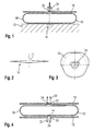
- FIG. 1 shows a first folding machine by means of which an airbag 10 can be pushed together, which has an injection opening 11 (see Figure 2).
- the gas bag 10 is placed on a base 12 of the folding machine laid out and fastened there by means of a tensioning device 14.
- the Clamping device 14 may, for example, at the edge of the injection opening 11th attack and tighten the gas bag on the base.
- the tensioning device 14 should clamp the gas bag to a surface, the possible later Base area of the finished finished installation airbag package corresponds.
- Opposite the pad 12 and parallel to this is a counter-holder 16 arranged, the distance from the base 12 of the height of the recording of a Housing corresponds, in which the collapsed airbag later should be arranged.
- Both the pad 12 and the anvil 16 are larger than the airbag 10, so extend beyond its outer edge.
- the airbag 10 is surrounded by a cable housing 18, whose one end 20 through a passage 22 in the anvil 16 from the space between the pad 12 and the counter-holder 16 is led out.
- the course of the implementation 22 by the anvil 16 corresponds to the contour that have the folded airbag should.
- a plunger 24 is arranged, which is the Course of the implementation 22 is adapted.
- the Stamp 24 for example, be trapezoidal, so that the implementation of the 22nd has a trapezoidal shape.
- the outer casing 18 can be carried like a bag with a closed wall be. Alternatively, it is possible to have a variety of side by side To use bands, for example, in the region of the clamping device 14 at the pad 12 are attached.
- the airbag At the beginning of the folding of the airbag 10, this is between the pad 12th and the counter-holder 16 unfolds. Due to the small distance between the Base 12 and the anvil 16, the airbag has a shape that is flattened towards his freely unfolded in the room state.
- the gas bag For unfolding the gas bag may be an inflator (not shown) used by the tensioning device 14 with the interior the gas bag is in fluid communication.
- FIG. 4 shows a second folding machine.
- the same reference numerals is used, and it is referred to the above explanations.
- a passage 30 is provided in the base 12.
- a second end 32 of the outer casing 18 is guided.
- a central element 34 is arranged, whose function corresponds to that of the punch 24 and that with the tensioning device 14th is provided.
- the airbag is at the second folding machine to the attracted to both ends of the outer casing 18, ie at the first end 20 upwards and at the second end 32 down.
- the outer casing 18 becomes symmetrical the space between the pad 12 and the anvil 16 pulled out, and the gas bag is symmetrical to the intended contour for him pushed together.
- the described method can also be used in a donut-shaped gas bag be applied, in which the gas bag by an annular chamber and one of the Inmates seen from indentation is marked.
Description
Die Erfindung betrifft ein Verfahren zum Falten eines Gassacks für ein Fahrzeuginsassen-Rückhaltesystem. Die Erfindung betrifft ferner einen gefalteten Gassack für ein Fahrzeuginsassen-Rückhaltesystem.The invention relates to a method for folding a gas bag for a The vehicle occupant restraint system. The invention further relates to a folded Airbag for a vehicle occupant restraint system.
Es sind eine Vielzahl von Verfahren bekannt, um einen Gassack für ein Fahrzeuginsassen-Rückhaltesystem aus einem ungefalteten Zustand in einen kompakt zusammengefalteten Zustand zu überführen, in welchem der Gassack in einem Gehäuse aufgenommen werden kann. Bei einem bekannten Verfahren werden Faltschwerter verwendet, die auf den Gassack aufgelegt werden und Faltkanten bilden, entlang denen der Gassack zusammengefaltet wird. Ein anderes bekanntes Verfahren verwendet Schieber, mit denen der Gassack zusammengeschoben wird. Der Nachteil aller dieser Verfahren liegt in dem hohen Aufwand zu seiner Durchführung.There are a variety of methods known to provide a gas bag for a Vehicle occupant restraint system from an unfolded state into one compact folded state to transfer, in which the gas bag in can be accommodated in a housing. In a known method Folding tabs are used, which are placed on the gas bag and Form folding edges along which the gas bag is folded. Another known method uses slides, with which the gas bag is pushed together. The disadvantage of all these methods lies in the high Effort to carry it out.
Ein weiteres Verfahren zum Falten eines Gassacks ist in der US 6 115 998 offenbart. Hierbei wird der Gassack mittels eines Zugbandes zusammengezogen, das sich um den kreisförmig ausgebreiteten Gassack erstreckt. Beim Falten wird der Gassack auf seinen Mittelpunkt zu zusammengezogen.Another method for folding a gas bag is described in US Pat. No. 6,115,998 disclosed. In this case, the gas bag is pulled together by means of a drawstring, which extends around the circular spreading gas bag. When folding is the gas bag tightened toward its midpoint.
Die Aufgabe der Erfindung besteht darin, ein Verfahren zum Falten eines Gassacks zu schaffen, das kostengünstig durchgeführt werden kann.The object of the invention is a method for folding a To create gas bags, which can be carried out inexpensively.
Zu diesem Zweck ist erfindungsgemäß ein Verfahren zum Falten eines Gassacks mittels der folgenden Schritte vorgesehen: Zunächst wird der Gassack zwischen einer Unterlage und einem Gegenhalter entfaltet, wobei sich um den Gassack herum eine Zughülle erstreckt, die an einem ersten Ende durch den Gegenhalter hindurchgeführt ist, wobei die Durchführung der Zughülle durch den Gegenhalter einen Verlauf hat, welcher der Kontur entspricht, die der gefaltete Gassack haben soll. Dann wird die Zughülle mittels des ersten Endes aus dem Raum zwischen der Unterlage und dem Gegenhalter herausgezogen, so daß der Gassack im Inneren der Zughülle zusammengeschoben wird. Der Gassack wird also, ohne daß aufwendig zu bewegende Schieber oder Faltschwerter notwendig sind, zwischen dem Gegenhalter und der Unterlage auf eine kompakte Form zusammengeschoben. Der Abstand zwischen der Unterlage und dem Gegenhalter entspricht dabei vorzugsweise der Höhe des Gehäuses, in dem der Gassack im zusammengefalteten Zustand aufgenommen wird. Die Abmessungen des Gassacks im zusammengeschobenen Zustand entsprechen dann exakt den Abmessungen der Aufnahme im Gehäuse.For this purpose, according to the invention, a method for folding a Gas bags provided by the following steps: First, the gas bag unfolded between a pad and a backstop, being about the Gas bag extends around a Zughülle, which at a first end by the Counter-holder is passed, the implementation of the case by the Contra-holder has a course corresponding to the contour that the folded Gas bag should have. Then the cable housing by means of the first end of the Room pulled out between the base and the anvil, so that the Airbag is pushed together inside the cable housing. The gas bag is So, without the need to move to moving slider or Faltschwerter necessary are, between the anvil and the pad on a compact form pushed together. The distance between the pad and the counterholder corresponds preferably to the height of the housing in which the gas bag in folded state is recorded. The dimensions of the Gas bags in the collapsed state correspond exactly to the Dimensions of the housing in the housing.
Gemäß einer Ausführungsform der Erfindung ist vorgesehen, daß die Zughülle ein zweites Ende hat, das durch eine Durchführung in der Unterlage geführt ist, wobei die Durchführung einen Verlauf hat, welcher der Kontur entspricht, die der gefaltete Gassack haben soll, und daß die Zughülle auch mittels des zweiten Endes aus dem Raum zwischen der Unterlage und dem Gegenhalter herausgezogen wird. Bei dieser Ausführungsform wird der Gassack symmetrisch zwischen der Unterlage und dem Gegenhalter zusammengeschoben, was das Ausmaß von Relativbewegungen zwischen der Zughülle und der Wandung des Gassacks verringert und zu gleichmäßigeren Falten in der Wandung des Gassacks führt.According to one embodiment of the invention it is provided that the outer casing has a second end, which is guided by a passage in the base, wherein the passage has a course corresponding to the contour which the folded airbag should have, and that the outer casing also by means of the second End of the space between the base and the counterholder is pulled out. In this embodiment, the gas bag is symmetrical pushed together between the pad and the anvil, which is the Extent of relative movement between the outer casing and the wall of the Gas bag reduced and more even folds in the wall of the gas bag leads.
Die Erfindung schafft auch einen Gassack, der mittels dem Verfahren gefaltet ist und dessen Wandung von außen nach innen zusammengeschoben ist und daher in einer Vielzahl von Einzelfalten verläuft. Dieser Gassack zeichnet sich dadurch aus, daß die Wandung des Gassacks in den Bereichen, in denen die geringste Relativbewegung gegenüber der Zughülle aufgetreten ist, die wenigsten Falten aufweist und in den anderen Bereichen entsprechend mehr Einzelfalten aufweist. Wenn die Zughülle nur an ihrem ersten Ende aus dem Raum zwischen Gegenhalter und Unterlage herausgezogen wird, weist die Wandung des Gassacks in ihrem der Durchführung gegenüberliegenden Bereich die geringste Anzahl von Einzelfalten auf. Im Bereich der Durchführung weist die Wandung dagegen die höchste Anzahl von Einzelfalten auf, da die Wandung dort von allen Seiten zusammengeschoben wird und nach unten chaotisch in das Innere des Gassacks hin ausweicht. Wenn die Zughülle an zwei Enden aus dem Raum zwischen Gegenhalter und Unterlage herausgezogen wird, wird die Wandung im Umfangsbereich des Gassacks die geringsten Falten aufweisen, da sie dort mit geringer Relativbewegung zwischen Zughülle und Wandung radial nach innen gedrückt wurde. Dagegen werden die Bereiche der Wandung des Gassacks, die unmittelbar gegenüber den beiden Durchführungen liegen, die meisten Einzelfalten aufweisen.The invention also provides an airbag folded by the method is and whose wall is pushed together from outside to inside and therefore runs in a variety of single folds. This gas bag is characterized from that the wall of the gas bag in the areas where the least Relative movement has occurred against the outer casing, the fewest wrinkles has and in the other areas correspondingly more individual folds. If the outer casing is only at its first end out of the space between Counterholder and pad is pulled out, has the wall of the gas bag in their implementation opposite area the smallest number of individual folds on. in the Area of implementation, the wall, however, has the highest number of Individually unfold, as the wall is pushed together from all sides and chaotically dodges down into the interior of the gas bag. If the Drawstring at two ends from the space between the backstop and underlay is pulled out, the wall in the peripheral region of the gas bag is the Have least wrinkles, since there with little relative movement between The outer casing and the wall were pressed radially inwards. In contrast, the Areas of the wall of the gas bag, which are directly opposite the two Bushings lie, most of which have individual folds.
Vorteilhafte Ausgestaltungen der Erfindung ergeben sich aus den Unteransprüchen.Advantageous embodiments of the invention will become apparent from the Dependent claims.
Die Erfindung wird nachfolgend anhand zweier Ausführungsformen beschrieben, die in den beigefügten Zeichnungen dargestellt sind. In diesen zeigen:
- Figur 1 in einer schematischen Schnittansicht eine Faltmaschine, mittels der ein Gassack gemäß einer ersten Ausführungsform der Erfindung zusammengeschoben werden kann;
- Figur 2 in einem schematischen S chnitt einen Gassack;
- Figur 3 in einer schematischen Draufsicht einen in einer Faltmaschine angeordneten Gassack; und
- Figur 4 in einer schematischen Schnittansicht eine zweite Faltmaschine, mittels der ein Gassack gemäß einer zweiten Ausführungsform der Erfindung zusammengeschoben werden kann.
- Figure 1 is a schematic sectional view of a folding machine, by means of which a gas bag according to a first embodiment of the invention can be pushed together;
- FIG. 2 is a schematic section through an airbag;
- FIG. 3 is a schematic top view of a gas bag arranged in a folding machine; and
- Figure 4 is a schematic sectional view of a second folding machine, by means of which a gas bag according to a second embodiment of the invention can be pushed together.
In Figur 1 ist eine erste Faltmaschine gezeigt, mittels der ein Gassack 10
zusammengeschoben werden kann, der eine Einblasöffnung 11 aufweist (siehe
Figur 2). Der Gassack 10 wird auf einer Unterlage 12 der Faltmaschine
ausgebreitet und dort mittels einer Spannvorrichtung 14 befestigt. Die
Spannvorrichtung 14 kann beispielsweise am Rand der Einblasöffnung 11
angreifen und den Gassack auf der Unterlage festspannen. Die Spannvorrichtung
14 sollte den Gassack an einer Fläche festspannen, die möglichst der späteren
Grundfläche des zum Einbau fertigen gefalteten Gassackpakets entspricht.
Gegenüber der Unterlage 12 und parallel zu dieser wird ein Gegenhalter 16
angeordnet, dessen Abstand von der Unterlage 12 der Höhe der Aufnahme eines
Gehäuses entspricht, in welchem der zusammengeschobene Gassack später
angeordnet werden soll. Sowohl die Unterlage 12 als auch der Gegenhalter 16
sind größer als der Gassack 10, reichen also über dessen Außenrand hinaus.FIG. 1 shows a first folding machine by means of which an
Der Gassack 10 ist von einer Zughülle 18 umgeben, deren eines Ende 20 durch
eine Durchführung 22 im Gegenhalter 16 aus dem Raum zwischen der Unterlage
12 und dem Gegenhalter 16 herausgeführt ist. Der Verlauf der Durchführung 22
durch den Gegenhalter 16 entspricht der Kontur, die der gefaltete Gassack haben
soll. Im Inneren der Durchführung 22 ist ein Stempel 24 angeordnet, der dem
Verlauf der Durchführung 22 angepaßt ist. Wie in Figur 3 zu sehen ist, kann der
Stempel 24 beispielsweise trapezförmig sein, so daß auch die Durchführung 22
einen trapezförmigen Verlauf hat.The
Die Zughülle 18 kann sackartig mit einer geschlossenen Wandung ausgeführt
sein. Alternativ ist es möglich, eine Vielzahl von nebeneinanderliegenden
Bändern zu verwenden, die beispielsweise im Bereich der Spannvorrichtung 14 an
der Unterlage 12 befestigt sind.The
Zu Beginn des Faltens des Gassacks 10 wird dieser zwischen der Unterlage 12
und dem Gegenhalter 16 entfaltet. Aufgrund des geringen Abstandes zwischen der
Unterlage 12 und dem Gegenhalter 16 hat der Gassack dabei eine Form, die
gegenüber seinem frei im Raum entfalteten Zustand stark abgeplattet ist.At the beginning of the folding of the
Zum Enfalten des Gassacks kann eine (nicht dargestellte) Aufblasvorrichtung
verwendet werden, die durch die Spannvorrichtung 14 hindurch mit dem Inneren
des Gassacks in Strömungsverbindung steht. For unfolding the gas bag may be an inflator (not shown)
used by the
Zum Zusammenschieben des Gassacks wird die Zughülle 18 aus dem Raum
zwischen der Unterlage 12 und dem Gegenhalter 16 durch die Durchführung 22
hindurch herausgezogen. Zu diesem Zweck wird einfach am ersten Ende 20 der
Zughülle 18 angezogen. Gleichzeitig entlüftet die Aufblasvorrichtung den
Gassack kontrolliert. Wenn die Zughülle 18 soweit wie möglich aus dem Raum
zwischen der Unterlage 12 und dem Gegenhalter 16 herausgezogen ist, hat der im
Inneren der Zughülle 18 zusammengeschobene Gassack 10 eine Kontur, die dem
Verlauf der Durchführung 22 entspricht, beispielsweise trapezförmig.To push the airbag, the cable housing 18 from the room
between the
In Figur 4 ist eine zweite Faltmaschine gezeigt. Für die von der ersten Ausführungsform bekannten Bauteile werden dieselben Bezugszeichen verwendet, und es wird auf die obigen Erläuterungen verwiesen.FIG. 4 shows a second folding machine. For those of the first Embodiment known components become the same reference numerals is used, and it is referred to the above explanations.
Im Unterschied zur ersten Ausführungsform ist bei der zweiten Faltmaschine
eine Durchführung 30 in der Unterlage 12 vorgesehen. Durch die zweite
Durchführung 30 ist ein zweites Ende 32 der Zughülle 18 geführt. Im Inneren der
zweiten Durchführung 30 ist ein Mittelelement 34 angeordnet, dessen Funktion
derjenigen des Stempels 24 entspricht und das mit der Spannvorrichtung 14
versehen ist.In contrast to the first embodiment, in the second folding machine
a
Zum Zusammenlegen des Gassacks wird bei der zweiten Faltmaschine an den
beiden Enden der Zughülle 18 angezogen, also am ersten Ende 20 nach oben und
am zweiten Ende 32 nach unten. Somit wird die Zughülle 18 symmetrisch aus
dem Raum zwischen der Unterlage 12 und dem Gegenhalter 16 herausgezogen,
und der Gassack wird symmetrisch auf die für ihn vorgesehene Kontur
zusammengeschoben.For collapsing the airbag is at the second folding machine to the
attracted to both ends of the
Das beschriebene Verfahren kann auch bei einem doughnut-förmigen Gassack angewandt werden, bei dem der Gassack durch eine Ringkammer und eine vom Insassen aus gesehene Einbuchtung gekennzeichnet ist.The described method can also be used in a donut-shaped gas bag be applied, in which the gas bag by an annular chamber and one of the Inmates seen from indentation is marked.
Claims (10)
- A method of folding a gas bag (10) for a vehicle occupant restraint system by means of the following steps:unfolding the gas bag between a base (12) and a hold-down (16), a traction envelope (18) extending around the gas bag (10) and being passed through the hold-down at a first end (20), the lead-through (22) of the traction envelope (18) through the hold-down (16) being contoured so as to correspond to the contour which the folded gas bag (10) is required to have;pulling out the traction envelope (18) from the space between the base (12) and the hold-down (16) by means of the first end (20), so that the gas bag (10) is pushed together inside the traction envelope (18).
- The method as set forth in claim 1, characterized in that a plunger (24) is arranged inside the lead-through (22) passing through the hold-down (16).
- The method as set forth in claim 1 or claim 2, characterized in that provided at the base (12) is a middle element (34) which is provided with a tensioning device (14) for the gas bag.
- The method as set forth in any of the preceding claims, characterized in that the traction envelope (18) has a second end guided through a lead-through (30) in the base (12), the lead-through (30) being contoured so as to correspond to the contour which the folded gas bag is required to have, and that the traction envelope (18) is pulled out from the space between the base (12) and the hold-down (16) also by means of the second end (32).
- The method as set forth in claim 3 and claim 4, characterized in that the middle element (34) is arranged inside the lead-through (30) passing through the base (12).
- The method as set forth in any of the preceding claims, characterized in that the traction envelope (18) has a closed wall.
- The method as set forth in any of the preceding claims, characterized in that the traction envelope (18) is formed of several bands arranged juxtaposed.
- A folded gas bag (10) comprising a wall and an inflation opening in the wall, characterized in that it has been folded by a method as set forth in any of the preceding claims and that the wall in the region of the lead-through has the highest number of single folds.
- A folded gas bag (10) comprising a wall and an inflation opening in the wall, characterized in that it has been folded by a method as set forth in any of the preceding claims and that it has comparatively few folds in the region of the inflation opening and comparatively many single folds in the region of the wall opposite the inflation opening.
- A folded gas bag (10) comprising a wall and an inflation opening in the wall, characterized in that the wall has the least number of single folds in the regions radially spaced away from the inflation opening.
Applications Claiming Priority (2)
| Application Number | Priority Date | Filing Date | Title |
|---|---|---|---|
| DE10145381 | 2001-09-14 | ||
| DE10145381A DE10145381A1 (en) | 2001-09-14 | 2001-09-14 | Method for folding an airbag for a vehicle occupant restraint system and folded airbag |
Publications (3)
| Publication Number | Publication Date |
|---|---|
| EP1293396A2 EP1293396A2 (en) | 2003-03-19 |
| EP1293396A3 EP1293396A3 (en) | 2003-10-22 |
| EP1293396B1 true EP1293396B1 (en) | 2005-10-12 |
Family
ID=7699061
Family Applications (1)
| Application Number | Title | Priority Date | Filing Date |
|---|---|---|---|
| EP02019109A Expired - Lifetime EP1293396B1 (en) | 2001-09-14 | 2002-08-29 | Method for folding an airbag for a vehicle passenger restraint system as well as the folded airbag |
Country Status (4)
| Country | Link |
|---|---|
| US (1) | US6910712B2 (en) |
| EP (1) | EP1293396B1 (en) |
| DE (2) | DE10145381A1 (en) |
| ES (1) | ES2250559T3 (en) |
Cited By (1)
| Publication number | Priority date | Publication date | Assignee | Title |
|---|---|---|---|---|
| DE102012010771A1 (en) | 2012-05-31 | 2013-12-05 | Trw Automotive Safety Systems Gmbh | Method for folding rider air bag for occupant restraint system of motor car, involves lifting part of compressed air bag from working face by using eccentrically engaging traction units so as to form one pleat in compressed air bag |
Families Citing this family (2)
| Publication number | Priority date | Publication date | Assignee | Title |
|---|---|---|---|---|
| DE202005010864U1 (en) * | 2004-11-15 | 2005-09-22 | Takata-Petri Ag | Airbag module for installation in motor vehicle has holding element and gas generator that are held on module housing by bayonet connection |
| WO2006050719A1 (en) * | 2004-11-15 | 2006-05-18 | Takata-Petri Ag | Module for an airbag device for the protection of the occupants of a vehicle |
Family Cites Families (14)
| Publication number | Priority date | Publication date | Assignee | Title |
|---|---|---|---|---|
| US5803892A (en) * | 1994-06-17 | 1998-09-08 | Petri Ag | Process for folding an airbag |
| DE19535565C2 (en) * | 1995-09-12 | 2002-09-05 | Takata Petri Ag | Process for folding an airbag and device for carrying out the folding process |
| DE29522155U1 (en) | 1995-09-12 | 2000-04-20 | Petri Ag | Device for folding an airbag for an airbag module |
| DE19546232B4 (en) * | 1995-09-22 | 2004-05-19 | Takata-Petri Ag | Device for folding an airbag for an airbag module |
| DE19702799C2 (en) * | 1996-05-28 | 2000-06-08 | Petri Ag | Airbag, method for folding it and device for carrying out the method |
| DE19648654A1 (en) * | 1996-11-15 | 1998-05-20 | Petri Ag | Airbag for an airbag module and method and device for folding an airbag |
| US6224100B1 (en) * | 1997-03-25 | 2001-05-01 | Nihon Plast Co., Ltd. | Air bag apparatus, air bag folding method, and air-bag folding device |
| US6595548B2 (en) * | 1998-03-20 | 2003-07-22 | Nihon Plast Co., Ltd. | Air bag system, method of folding air bag and air bag folding apparatus |
| DE19831613A1 (en) * | 1998-07-14 | 2000-01-20 | Delphi Automotive Systems Gmbh | Method and device for folding an inflatable air bag |
| CA2339160C (en) * | 1998-09-14 | 2005-01-25 | Breed Automotive Technology, Inc. | Method and apparatus for folding an airbag |
| DE19845721A1 (en) | 1998-10-05 | 2000-04-06 | Takata Europ Gmbh | Procedure for folding an airbag |
| DE19901472A1 (en) | 1999-01-15 | 2000-07-20 | Takata Europ Gmbh | Folding air bag used in vehicle interiors involves using folding element which defines bag periphery |
| DE10050570A1 (en) * | 2000-10-12 | 2002-06-13 | Trw Automotive Safety Sys Gmbh | Device and method for collapsing an airbag and collapsed airbag |
| DE10162233B4 (en) * | 2001-12-18 | 2006-04-20 | Key Safety Systems, Inc., Sterling Heights | Airbag folding method and device |
-
2001
- 2001-09-14 DE DE10145381A patent/DE10145381A1/en not_active Withdrawn
-
2002
- 2002-08-29 DE DE50204512T patent/DE50204512D1/en not_active Expired - Fee Related
- 2002-08-29 ES ES02019109T patent/ES2250559T3/en not_active Expired - Lifetime
- 2002-08-29 EP EP02019109A patent/EP1293396B1/en not_active Expired - Lifetime
- 2002-09-13 US US10/243,504 patent/US6910712B2/en not_active Expired - Fee Related
Cited By (1)
| Publication number | Priority date | Publication date | Assignee | Title |
|---|---|---|---|---|
| DE102012010771A1 (en) | 2012-05-31 | 2013-12-05 | Trw Automotive Safety Systems Gmbh | Method for folding rider air bag for occupant restraint system of motor car, involves lifting part of compressed air bag from working face by using eccentrically engaging traction units so as to form one pleat in compressed air bag |
Also Published As
| Publication number | Publication date |
|---|---|
| DE50204512D1 (en) | 2005-11-17 |
| US20030052480A1 (en) | 2003-03-20 |
| EP1293396A2 (en) | 2003-03-19 |
| ES2250559T3 (en) | 2006-04-16 |
| EP1293396A3 (en) | 2003-10-22 |
| DE10145381A1 (en) | 2003-08-07 |
| US6910712B2 (en) | 2005-06-28 |
Similar Documents
| Publication | Publication Date | Title |
|---|---|---|
| DE19535564C2 (en) | Method and device for folding an airbag for an airbag module | |
| DE4422276C2 (en) | Airbag, method for its folding and device for carrying out the folding method | |
| EP0972683B1 (en) | Method and means of folding an inflatable air bag | |
| DE19516494C1 (en) | Method of folding an airbag for an occupant restraint system | |
| EP0967125B1 (en) | Method and means for folding an inflatable air bag | |
| DE602004008370T2 (en) | Occupant leg protection apparatus | |
| EP0851818B1 (en) | Method and device for folding air bags | |
| WO1997010123A1 (en) | Airbag, method of folding it and device for carrying out the method | |
| DE102008061693A1 (en) | Method and device for folding a gas bag for an airbag module | |
| DE19702799C2 (en) | Airbag, method for folding it and device for carrying out the method | |
| EP0936981A1 (en) | Gasbag for an airbag module, method and device for folding a gas bag | |
| EP1149741A2 (en) | Folding method and device | |
| DE19536625C2 (en) | Method for folding an airbag and device for carrying out the folding | |
| EP1293396B1 (en) | Method for folding an airbag for a vehicle passenger restraint system as well as the folded airbag | |
| DE19704670B4 (en) | A method of collapsing a side impact airbag for a vehicle occupant restraint system, collapsed side impact airbag, and apparatus for collapsing a side impact airbag | |
| EP0853026B1 (en) | Airbag for an occupant restraint system and a method and an apparatus for folding said airbag | |
| EP1179455B9 (en) | Method for folding an airbag and device for carrying out this method | |
| DE102006031117B4 (en) | Method for assembling an airbag assembly and airbag assembly | |
| DE10248532A1 (en) | Method for folding airbag comprises first folding it zigzag-fashion, resulting packet then being folded in two across middle | |
| EP0965498A2 (en) | Device and method for folding an airbag | |
| EP1293395B1 (en) | Method for folding an airbag for a vehicle passenger restraint system as well as the folded airbag | |
| EP1197401B1 (en) | Process and device for folding an airbag and airbag folded thereby | |
| DE19702147A1 (en) | Vehicle airbag folding - by inflating airbag between support and cover plate for sliding folding blades to push side wall inwards in pleats | |
| DE10196171B4 (en) | Device and method for folding an airbag | |
| DE10144776A1 (en) | Folding method for airbag for motor vehicles with flat airbag folded inwards in several stages to form to parcels, for quick and complete inflation |
Legal Events
| Date | Code | Title | Description |
|---|---|---|---|
| PUAI | Public reference made under article 153(3) epc to a published international application that has entered the european phase |
Free format text: ORIGINAL CODE: 0009012 |
|
| AK | Designated contracting states |
Kind code of ref document: A2 Designated state(s): AT BE BG CH CY CZ DE DK EE ES FI FR GB GR IE IT LI LU MC NL PT SE SK TR Designated state(s): AT BE BG CH CY CZ DE DK EE ES FI FR GB GR IE IT LI LU MC NL PT SE SK TR |
|
| AX | Request for extension of the european patent |
Extension state: AL LT LV MK RO SI |
|
| PUAL | Search report despatched |
Free format text: ORIGINAL CODE: 0009013 |
|
| AK | Designated contracting states |
Kind code of ref document: A3 Designated state(s): AT BE BG CH CY CZ DE DK EE ES FI FR GB GR IE IT LI LU MC NL PT SE SK TR |
|
| AX | Request for extension of the european patent |
Extension state: AL LT LV MK RO SI |
|
| 17P | Request for examination filed |
Effective date: 20040407 |
|
| AKX | Designation fees paid |
Designated state(s): DE ES FR GB IT |
|
| 17Q | First examination report despatched |
Effective date: 20040630 |
|
| GRAP | Despatch of communication of intention to grant a patent |
Free format text: ORIGINAL CODE: EPIDOSNIGR1 |
|
| GRAS | Grant fee paid |
Free format text: ORIGINAL CODE: EPIDOSNIGR3 |
|
| GRAA | (expected) grant |
Free format text: ORIGINAL CODE: 0009210 |
|
| RAP1 | Party data changed (applicant data changed or rights of an application transferred) |
Owner name: TRW AUTOMOTIVE SAFETY SYSTEMS GMBH |
|
| AK | Designated contracting states |
Kind code of ref document: B1 Designated state(s): DE ES FR GB IT |
|
| PG25 | Lapsed in a contracting state [announced via postgrant information from national office to epo] |
Ref country code: GB Free format text: LAPSE BECAUSE OF FAILURE TO SUBMIT A TRANSLATION OF THE DESCRIPTION OR TO PAY THE FEE WITHIN THE PRESCRIBED TIME-LIMIT Effective date: 20051012 |
|
| REG | Reference to a national code |
Ref country code: GB Ref legal event code: FG4D Free format text: NOT ENGLISH |
|
| REF | Corresponds to: |
Ref document number: 50204512 Country of ref document: DE Date of ref document: 20051117 Kind code of ref document: P |
|
| REG | Reference to a national code |
Ref country code: ES Ref legal event code: FG2A Ref document number: 2250559 Country of ref document: ES Kind code of ref document: T3 |
|
| GBV | Gb: ep patent (uk) treated as always having been void in accordance with gb section 77(7)/1977 [no translation filed] |
Effective date: 20051012 |
|
| ET | Fr: translation filed | ||
| PGFP | Annual fee paid to national office [announced via postgrant information from national office to epo] |
Ref country code: FR Payment date: 20060803 Year of fee payment: 5 |
|
| PGFP | Annual fee paid to national office [announced via postgrant information from national office to epo] |
Ref country code: ES Payment date: 20060804 Year of fee payment: 5 |
|
| PLBE | No opposition filed within time limit |
Free format text: ORIGINAL CODE: 0009261 |
|
| STAA | Information on the status of an ep patent application or granted ep patent |
Free format text: STATUS: NO OPPOSITION FILED WITHIN TIME LIMIT |
|
| PGFP | Annual fee paid to national office [announced via postgrant information from national office to epo] |
Ref country code: IT Payment date: 20060831 Year of fee payment: 5 Ref country code: DE Payment date: 20060831 Year of fee payment: 5 |
|
| 26N | No opposition filed |
Effective date: 20060713 |
|
| REG | Reference to a national code |
Ref country code: FR Ref legal event code: ST Effective date: 20080430 |
|
| PG25 | Lapsed in a contracting state [announced via postgrant information from national office to epo] |
Ref country code: DE Free format text: LAPSE BECAUSE OF NON-PAYMENT OF DUE FEES Effective date: 20080301 |
|
| PG25 | Lapsed in a contracting state [announced via postgrant information from national office to epo] |
Ref country code: FR Free format text: LAPSE BECAUSE OF NON-PAYMENT OF DUE FEES Effective date: 20070831 |
|
| REG | Reference to a national code |
Ref country code: ES Ref legal event code: FD2A Effective date: 20070830 |
|
| PG25 | Lapsed in a contracting state [announced via postgrant information from national office to epo] |
Ref country code: ES Free format text: LAPSE BECAUSE OF NON-PAYMENT OF DUE FEES Effective date: 20070830 |
|
| PG25 | Lapsed in a contracting state [announced via postgrant information from national office to epo] |
Ref country code: IT Free format text: LAPSE BECAUSE OF NON-PAYMENT OF DUE FEES Effective date: 20070829 |