EP1293381B1 - System zur Erfassung und Anzeige des Abstandes von Fahrzeugen zu Hindernissen sowie Stossfänger - Google Patents
System zur Erfassung und Anzeige des Abstandes von Fahrzeugen zu Hindernissen sowie Stossfänger Download PDFInfo
- Publication number
- EP1293381B1 EP1293381B1 EP02017880A EP02017880A EP1293381B1 EP 1293381 B1 EP1293381 B1 EP 1293381B1 EP 02017880 A EP02017880 A EP 02017880A EP 02017880 A EP02017880 A EP 02017880A EP 1293381 B1 EP1293381 B1 EP 1293381B1
- Authority
- EP
- European Patent Office
- Prior art keywords
- control unit
- bumper
- distance
- distance measuring
- central control
- Prior art date
- Legal status (The legal status is an assumption and is not a legal conclusion. Google has not performed a legal analysis and makes no representation as to the accuracy of the status listed.)
- Expired - Lifetime
Links
- 238000004891 communication Methods 0.000 claims abstract description 10
- 238000000034 method Methods 0.000 claims description 6
- 230000004913 activation Effects 0.000 claims description 5
- 230000003287 optical effect Effects 0.000 claims description 5
- 230000008569 process Effects 0.000 claims description 5
- 230000009849 deactivation Effects 0.000 claims description 3
- 239000004020 conductor Substances 0.000 abstract 1
- 230000000007 visual effect Effects 0.000 abstract 1
- 230000008901 benefit Effects 0.000 description 6
- 238000005259 measurement Methods 0.000 description 5
- 230000005540 biological transmission Effects 0.000 description 2
- 238000011156 evaluation Methods 0.000 description 2
- 230000003213 activating effect Effects 0.000 description 1
- 230000000712 assembly Effects 0.000 description 1
- 238000000429 assembly Methods 0.000 description 1
- 238000001514 detection method Methods 0.000 description 1
- 238000009434 installation Methods 0.000 description 1
- 238000012545 processing Methods 0.000 description 1
- 230000005855 radiation Effects 0.000 description 1
- 239000000523 sample Substances 0.000 description 1
Images

Classifications
-
- B—PERFORMING OPERATIONS; TRANSPORTING
- B60—VEHICLES IN GENERAL
- B60Q—ARRANGEMENT OF SIGNALLING OR LIGHTING DEVICES, THE MOUNTING OR SUPPORTING THEREOF OR CIRCUITS THEREFOR, FOR VEHICLES IN GENERAL
- B60Q9/00—Arrangement or adaptation of signal devices not provided for in one of main groups B60Q1/00 - B60Q7/00, e.g. haptic signalling
- B60Q9/002—Arrangement or adaptation of signal devices not provided for in one of main groups B60Q1/00 - B60Q7/00, e.g. haptic signalling for parking purposes, e.g. for warning the driver that his vehicle has contacted or is about to contact an obstacle
- B60Q9/007—Arrangement or adaptation of signal devices not provided for in one of main groups B60Q1/00 - B60Q7/00, e.g. haptic signalling for parking purposes, e.g. for warning the driver that his vehicle has contacted or is about to contact an obstacle providing information about the distance to an obstacle, e.g. varying sound
-
- G—PHYSICS
- G01—MEASURING; TESTING
- G01S—RADIO DIRECTION-FINDING; RADIO NAVIGATION; DETERMINING DISTANCE OR VELOCITY BY USE OF RADIO WAVES; LOCATING OR PRESENCE-DETECTING BY USE OF THE REFLECTION OR RERADIATION OF RADIO WAVES; ANALOGOUS ARRANGEMENTS USING OTHER WAVES
- G01S15/00—Systems using the reflection or reradiation of acoustic waves, e.g. sonar systems
- G01S15/87—Combinations of sonar systems
- G01S15/876—Combination of several spaced transmitters or receivers of known location for determining the position of a transponder or a reflector
-
- G—PHYSICS
- G01—MEASURING; TESTING
- G01S—RADIO DIRECTION-FINDING; RADIO NAVIGATION; DETERMINING DISTANCE OR VELOCITY BY USE OF RADIO WAVES; LOCATING OR PRESENCE-DETECTING BY USE OF THE REFLECTION OR RERADIATION OF RADIO WAVES; ANALOGOUS ARRANGEMENTS USING OTHER WAVES
- G01S15/00—Systems using the reflection or reradiation of acoustic waves, e.g. sonar systems
- G01S15/88—Sonar systems specially adapted for specific applications
- G01S15/93—Sonar systems specially adapted for specific applications for anti-collision purposes
- G01S15/931—Sonar systems specially adapted for specific applications for anti-collision purposes of land vehicles
-
- H—ELECTRICITY
- H04—ELECTRIC COMMUNICATION TECHNIQUE
- H04L—TRANSMISSION OF DIGITAL INFORMATION, e.g. TELEGRAPHIC COMMUNICATION
- H04L69/00—Network arrangements, protocols or services independent of the application payload and not provided for in the other groups of this subclass
- H04L69/28—Timers or timing mechanisms used in protocols
-
- G—PHYSICS
- G01—MEASURING; TESTING
- G01S—RADIO DIRECTION-FINDING; RADIO NAVIGATION; DETERMINING DISTANCE OR VELOCITY BY USE OF RADIO WAVES; LOCATING OR PRESENCE-DETECTING BY USE OF THE REFLECTION OR RERADIATION OF RADIO WAVES; ANALOGOUS ARRANGEMENTS USING OTHER WAVES
- G01S15/00—Systems using the reflection or reradiation of acoustic waves, e.g. sonar systems
- G01S15/88—Sonar systems specially adapted for specific applications
- G01S15/93—Sonar systems specially adapted for specific applications for anti-collision purposes
- G01S15/931—Sonar systems specially adapted for specific applications for anti-collision purposes of land vehicles
- G01S2015/932—Sonar systems specially adapted for specific applications for anti-collision purposes of land vehicles for parking operations
-
- G—PHYSICS
- G01—MEASURING; TESTING
- G01S—RADIO DIRECTION-FINDING; RADIO NAVIGATION; DETERMINING DISTANCE OR VELOCITY BY USE OF RADIO WAVES; LOCATING OR PRESENCE-DETECTING BY USE OF THE REFLECTION OR RERADIATION OF RADIO WAVES; ANALOGOUS ARRANGEMENTS USING OTHER WAVES
- G01S15/00—Systems using the reflection or reradiation of acoustic waves, e.g. sonar systems
- G01S15/88—Sonar systems specially adapted for specific applications
- G01S15/93—Sonar systems specially adapted for specific applications for anti-collision purposes
- G01S15/931—Sonar systems specially adapted for specific applications for anti-collision purposes of land vehicles
- G01S2015/937—Sonar systems specially adapted for specific applications for anti-collision purposes of land vehicles sensor installation details
- G01S2015/938—Sonar systems specially adapted for specific applications for anti-collision purposes of land vehicles sensor installation details in the bumper area
-
- H—ELECTRICITY
- H04—ELECTRIC COMMUNICATION TECHNIQUE
- H04L—TRANSMISSION OF DIGITAL INFORMATION, e.g. TELEGRAPHIC COMMUNICATION
- H04L67/00—Network arrangements or protocols for supporting network services or applications
- H04L67/01—Protocols
- H04L67/12—Protocols specially adapted for proprietary or special-purpose networking environments, e.g. medical networks, sensor networks, networks in vehicles or remote metering networks
Definitions
- the invention relates to a system for detecting and displaying the distance from vehicles to obstacles, with a central control unit, with a plurality of distance measuring sensors and with an acoustic and / or optical distance display device, wherein the central control unit with the distance measuring sensors, with the distance indicator and with other vehicle systems, in particular a BUS system and / or a button and / or a speed measuring system connected.
- the central control unit regularly fulfills a multiplicity of system functions, which include: communication with the sensors, voltage and ground supply of the sensors, control of driver information systems, evaluation of different vehicle states and different operating elements, evaluation of BUS information, output of diagnostic information, storage of coding data sensors and bumper-specific data.
- the distance display device displays the distance between the vehicle and the obstacle, for example acoustically via loudspeakers or optically via displays.
- buttons, direction detection systems, speed measurement systems, trailers, if any, and / or diagnostic interfaces can also be transmitted via a BUS system of the central control unit.
- the known systems generally include between two to six distance measuring sensors in the bumper area.
- the distance measuring sensors can be designed, for example, as ultrasonic sensors, radar sensors, optical sensors and / or similar sensors, possibly with associated subsystems. Between the sensors and the central control unit, a relatively high cabling is to operate.
- A1 sensor carrier for a distance radar system has become known in which a system processor that collects information generated by sensors, and a vehicle processor that evaluates the information of the system processor provided.
- the present invention is therefore based on the object to significantly reduce the wiring effort within the vehicle.
- the invention has the advantage that cabling expenditure between the central control unit and the respective distance measuring sensors is eliminated.
- wiring between the decentralized control unit and the individual distance measuring sensors requires supply and communication of the sensors with the decentralized control unit.
- only the decentralized control unit communicates directly with the distance measuring sensors. The of The distance information acquired by the distance measuring sensors is thus sent from the decentralized control unit via the BUS system to the central control unit.
- the BUS system may be a CAN or LIN BUS system.
- the implementation of the distance information transmitted via the BUS system of the central control unit preferably takes place in the central control unit which controls the distance indicator.
- the functions of the central control unit can be divided into several, the central control unit downstream further control units.
- the control console ECU can control the activation, the on-board computer ECU the optical display and the on-board radio the acoustic display.
- the distance measuring sensors and also the decentralized control unit are arranged in the region of a bumper of the vehicle. Due to the spatial proximity between the decentralized control unit and the corresponding sensors cabling can be minimized.
- the decentralized control unit stores and processes coding data of the distance measuring sensors. This has the advantage that the central control unit can be preprogrammed independently of the distance measuring sensors ultimately installed in the bumper.
- the distance-measuring sensor-specific coding data are stored in the decentralized control unit, which is preferably to be arranged on the bumper.
- the decentralized control unit stores and processes bumper-specific data.
- the measurement behavior of the distance measuring sensors is fundamentally influenced by the nature of the bumpers, ie bumper-specific data.
- the bumper-specific data may include the spatial geometries of the bumper on the one hand, and also the surface condition and the radiation behavior of the bumper on the other hand. If the bumper and the distance measuring sensor are painted accordingly, do so especially in distance measuring sensors in the form of ultrasonic transducers on very different measurements.
- the central control unit can be programmed uniformly for different types of bumpers.
- a further embodiment of the invention is characterized in that the decentralized control unit reads and processes activation and / or deactivation information sent by the central control unit via the BUS system.
- This has the advantage that an activation or deactivation of the decentralized control unit and the sensors can take place in a targeted and uniform manner by the central control unit.
- connection between the central control unit and the decentralized control unit has a detachable interface.
- the invention also has the advantage that the bumper can be designed as a separate assembly to handle and both the bumper and the distance measurement sensor specific data of the bumper can be placed in the remote control unit.
- the central control unit may be unitarily programmed for various types of bumper and / or range sensor applications.
- all distance measurement sensor and bumper-specific data relevant for determining the distance between the bumper and the vehicle are stored in the decentralized control unit.
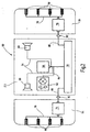
- Fig. 1 shows a known system 10 for detecting and displaying the distance from vehicles to obstacles.
- a vehicle 12 having on its front side a front bumper 14 and at its rear side has a rear bumper 16.
- the system 10 comprises on the vehicle side a central control unit 18, an acoustic distance indicator 20 in the form of two loudspeakers and an optical distance indicator 22 in the form of a lighting unit.
- the display devices 20 and 22 are connected via supply and communication lines 24 to the central control unit 18.
- the central control unit 18 is also connected via a bus system 25 to other vehicle systems. These include in particular a speed measuring system and a probe system for manually activating and deactivating the system 10.
- the system 10 further comprises four distance measuring sensors 26, 28 on each bumper 14, 16.
- the distance measuring sensors 26, 28 are connected to the central control unit 18 by means of supply and communication lines 30 and 32.
- the Fig. 2 shows a system 50 according to the invention for detecting and displaying the distance from vehicles to obstacles.
- the Fig. 2 shows accordingly Fig. 1 a vehicle 52 having a front bumper 54 and a rear bumper 56.
- the vehicle side are according to the Fig. 1 a central control unit 58, display devices 60 and 62 and associated lines 64 shown. Further, the central control unit 58 is connected to a BUS system 55.
- the bumpers 54 and 56 also respectively provide four distance measuring sensors 66 and 68.
- each bumper 54, 56 are each a decentralized control unit 74, 76.
- the decentralized control units 74, 76 are connected via supply and communication lines 78 to the respective sensors 66, 68.
- the remote control units 74, 76 are also connected via lines 80 to the BUS system 55.
- the in the Fig. 2 illustrated embodiment of the invention also has the advantage that all sensor-specific data and all bumper specific data in the respective bumpers 54, 56 associated decentralized control unit 74, 76 are stored.
- the programming of the central control unit 54 can thus be carried out independently of the embodiments of the bumpers 54, 56 as well as independently of the embodiments of the sensors 66, 68.
- the bumpers 54, 56 with the sensors 66, 68 and the remote control units 74, 76 can be handled as separate assemblies.
- removable interfaces 82 are provided on the lines.
- the decentralized control units 74, 76 have the following functions: communication with the sensors 66, 68, voltage and ground supply of the sensors 66, 68, transmission of distance information from the sensors 66, 68 via the BUS system 55 to the central control unit 58, Read and Processing activation information sent from the central control unit 58 via the BUS system 55 to the remote control units 74, 76, storing coding data of the sensors and bumper-specific data.
Landscapes
- Engineering & Computer Science (AREA)
- Remote Sensing (AREA)
- Radar, Positioning & Navigation (AREA)
- Physics & Mathematics (AREA)
- Computer Networks & Wireless Communication (AREA)
- General Physics & Mathematics (AREA)
- Mechanical Engineering (AREA)
- Signal Processing (AREA)
- Acoustics & Sound (AREA)
- Computer Security & Cryptography (AREA)
- Human Computer Interaction (AREA)
- Transportation (AREA)
- Measurement Of Velocity Or Position Using Acoustic Or Ultrasonic Waves (AREA)
- Radar Systems Or Details Thereof (AREA)
- Traffic Control Systems (AREA)
Description
- Die Erfindung betrifft ein System zur Erfassung und Anzeige des Abstandes von Fahrzeugen zu Hindernissen, mit einer zentralen Steuereinheit, mit mehreren Abstandsmesssensoren und mit einem akustischen und/oder optischen Abstandsanzeigegerät, wobei die zentrale Steuereinheit mit den Abstandsmesssensoren, mit dem Abstandsanzeigegerät und mit weiteren Fahrzeugsystemen, insbesondere einem BUS-System und/oder einem Taster und/oder einem Geschwindigkeitsmesssystem, verbunden ist.
- Die zentrale Steuereinheit erfüllt regelmäßig eine Vielzahl von Systemfunktionen, zu denen zählen: Kommunikation mit den Sensoren, Spannungs- und Masseversorgung der Sensoren, Ansteuerung von Fahrerinformationssystemen, Auswertung unterschiedlicher Fahrzeugzustände und unterschiedlicher Bedienelementen, Auswertung von BUS-Informationen, Ausgabe von Diagnoseinformationen, Speicherung von Codierdaten der Sensoren und von stoßfängerspezifischen Daten.
- Das Abstandsanzeigegerät zeigt den Abstand zwischen Fahrzeug und Hindernis beispielsweise akustisch über Lautsprecher oder optisch über Displays an.
- Zur zentralen Steuereinheit führen entweder separate Leitungen von Tastern, von Fahrtrichtungserkennungssystemen, von Geschwindigkeitsmesssystemen, von Anhängern, falls solche vorhanden sind, und/oder von Diagnoseschnittstellen. Bei moderneren Fahrzeugen können diese Informationen auch über ein BUS-System der zentralen Steuereinheit übermittelt werden.
- Die bekannten Systeme umfassen in der Regel zwischen zwei bis sechs Abstandsmesssensoren im Bereich der Stoßfänger. Die Abstandsmesssensoren können beispielsweise als Ultraschallsensoren, Radarsensoren, optische Sensoren und/oder ähnliche Sensoren, ggf. mit zugehörigen Subsystemen, ausgebildet sein. Zwischen den Sensoren und der zentralen Steuereinheit ist ein relativ hoher Verkabelungsaufwand zu betreiben.
- Aus der gattungsbildenden WO 01/65519 A1 ist Sensorträger für ein Abstandsradarsystem bekannt geworden, bei dem ein Systemprozessor, der von Sensoren erzeugte Informationen sammelt, und ein Fahrzeugprozessor, der die Informationen des Systemprozessor auswertet, vorgesehen.
- Aus der
DE 100 37 129 A1 ist eine Einpark- und Rangierhilfeeinrichtung bekannt geworden, bei der neben einer Steuereinheit für Radarsensoren auch ein übergeordnetes Steuergerät vorgesehen ist. - Aus der
DE 199 09 535 C1 ist ein Datenübertragungsverfahren bekannt geworden, bei dem mehrere Steuereinheiten Verwendung finden. - Der vorliegenden Erfindung liegt deshalb die Aufgabe zugrunde, den Verkabelungsaufwand innerhalb des Fahrzeuges erheblich zu reduzieren.
- Diese Aufgabe wird mit einem System mit den Merkmalen des Anspruchs 1 gelöst.
- Die Erfindung hat den Vorteil, dass Verkabelungsaufwand zwischen der zentralen Steuereinheit und den jeweiligen Abstandsmesssensoren entfällt. Durch Anbinden der dezentralen Steuereinheit an die zentrale Steuereinheit über ein BUS-System ist lediglich zwischen der dezentralen Steuereinheit und den einzelnen Abstandsmesssensoren eine Verkabelung für die Versorgung und die Kommunikation der Sensoren mit der dezentralen Steuereinheit erforderlich. Vorteilhafterweise kommuniziert lediglich die dezentrale Steuereinheit direkt mit den Abstandsmesssensoren. Die von den Abstandsmesssensoren erfassten Abstandsinformationen werden also von der dezentralen Steuereinheit über das BUS-System an die zentrale Steuereinheit gesendet. Bei dem BUS-System kann es sich um ein CAN- oder LIN-BUS-System handeln.
- Die Umsetzung der über das BUS-System der zentralen Steuereinheit übersandten Abstandsinformationen erfolgt vorzugsweise in der zentralen Steuereinheit, die das Abstandsanzeigegerät steuert.
- Dabei können die Funktionen des zentralen Steuergeräts auf mehrere, dem zentralen Steuergerät nachgeschaltete weitere Steuereinheiten, aufgeteilt sein. So kann beispielsweise der Schaltkonsolen ECU die Aktivierung, der Bordcomputer ECU die optische Anzeige und das Bordradio die akustische Anzeige steuern.
- Gemäß der Erfindung sind die Abstandsmesssensoren und auch die dezentrale Steuereinheit im Bereich eines Stoßfängers des Fahrzeuges angeordnet. Aufgrund der räumlichen Nähe zwischen der dezentralen Steuereinheit und den entsprechenden Sensoren kann Verkabelungsaufwand minimiert werden.
- Denkbar ist auch, dass im Bereich eines vorderen Stoßfängers Abstandsmesssensoren und eine erste dezentrale Steuereinheit und im Bereich des hinteren Stoßfängers Abstandsmesssensoren und eine zweite dezentrale Steuereinheit angeordnet sind. Auch hierdurch wird im Fahrzeug erheblicher Verkabelungsaufwand eingespart.
- Bei der Erfindung ist zudem vorgesehen, dass die dezentrale Steuereinheit Codierdaten der Abstandsmesssensoren speichert und verarbeitet. Dies hat den Vorteil, dass die zentrale Steuereinheit unabhängig von den letztlich im Stoßfänger verbauten Abstandsmesssensoren vorprogrammiert werden kann. Die abstandsmesssensorspezifischen Codierdaten werden in der vorzugsweise am Stoßfänger anzuordnenden dezentralen Steuereinheit abgelegt.
- Ferner ist vorgesehen, dass die dezentrale Steuereinheit stoßfängerspezifische Daten speichert und verarbeitet. Das Messverhalten der Abstandsmesssensoren wird grundsätzlich von der Beschaffenheit der Stoßfänger, d.h. von stoßfängerspezifischen Daten, beeinflusst. Die stoßfängerspezifischen Daten können hierbei zum einen die räumlichen Geometrien des Stoßfängers, zum anderen auch die Oberflächenbeschaffenheit und das Abstrahlverhalten des Stoßfängers beinhalten. Bei entsprechenden Lackierungen des Stoßfängers und u.U. auch des Abstandsmesssensors treten insbesondere bei Abstandsmesssensoren in Form von Ultraschallwandlern sehr unterschiedliche Messwerte auf. Dadurch, dass die stoßfängerspezifischen Daten in der dezentralen Steuereinheit, die vorteilhafterweise am Stoßfänger selbst angeordnet ist, abgelegt werden, kann die zentrale Steuereinheit einheitlich, für verschiedene Arten von Stoßfängern, programmiert werden.
- Eine weitere Ausführungsform der Erfindung kennzeichnet sich dadurch, dass die dezentrale Steuereinheit von der zentralen Steuereinheit über das BUS-System gesendete Aktivierungs- und/oder Deaktivierungsinformationen liest und verarbeitet. Dies hat den Vorteil, dass eine Aktivierung bzw. eine Deaktivierung der dezentralen Steuereinheit und der Sensoren gezielt und einheitlich von der zentralen Steuereinheit erfolgen kann. Beim Rückwärtsfahren werden so beispielsweise nur die im Heckstoßfänger vorhandenen Abstandsmesssensoren mit zugehöriger dezentralen Steuereinheit aktiviert. Beim Vorwärtseinparken werden entsprechend nur die im Frontstoßfänger angeordneten Abstandsmesssensoren mit zugehöriger dezentralen Steuereinheit aktiviert.
- Zur vorteilhaften und einfachen Montage eines Stoßfängers mit dezentraler Steuereinheit und entsprechenden Abstandsmesssensoren ist erfindungsgemäß vorgesehen, dass die Verbindung zwischen der zentralen Steuereinheit und der dezentralen Steuereinheit eine lösbare Schnittstelle aufweist.
- Die Erfindung hat auch den Vorteil, dass der Stoßfänger als separat handzuhabende Baugruppe ausgebildet sein kann und sowohl die stoßfänger- als auch die abstandsmesssensorspezifischen Daten des Stoßfängers in der dezentralen Steuereinheit niedergelegt werden können. Die zentrale Steuereinheit kann demnach für verschiedene Stoßfänger- und/oder Abstandsmesssensorausführungen einheitlich programmiert werden. Vorteilhafterweise sind alle abstandsmesssensor- und stoßfängerspezifischen Daten, die zur Bestimmung des Abstands zwischen dem Stoßfänger und dem Fahrzeug relevant sind, in der dezentralen Steuereinheit niedergelegt.
- Weitere Vorteile und vorteilhafte Ausgestaltungen der Erfindung sind der nachfolgenden Beschreibung zu entnehmen, in der die Erfindung anhand eines Ausführungsbeispiels näher beschrieben und erläutert ist.
- In der Zeichnung zeigen:
- Fig. 1:
- ein System zur Erfassung und Anzeige des Abstandes von Fahrzeugen zu Hindernissen nach dem bekannten Stand der Technik; und
- Fig. 2:
- ein erfindungsgemäßes System zur Erfassung und Anzeige des Abstandes von Fahrzeugen zu Hindernissen.
-
Fig. 1 zeigt ein bekanntes System 10 zur Erfassung und Anzeige des Abstandes von Fahrzeugen zu Hindernissen. Schematisch angedeutet ist ein Fahrzeug 12, das an seiner vorderen Seite einen Frontstoßfänger 14 und an seiner hinteren Seite einen Hecksstoßfänger 16 aufweist. Das System 10 umfasst fahrzeugseitig eine zentrale Steuereinheit 18, ein akustisches Abstandsanzeigegerät 20 in Form von zwei Lautsprechern und ein optisches Abstandsanzeigegerät 22 in Form einer Beleuchtungseinheit. Die Anzeigegeräte 20 und 22 sind über Versorgungs- und Kommunikationsleitungen 24 mit der zentralen Steuereinheit 18 verbunden. - Die zentrale Steuereinheit 18 ist außerdem über ein BUS-System 25 mit weiteren Fahrzeugsystemen verbunden. Hierzu zählen insbesondere ein Geschwindigkeitsmesssystem sowie ein Tastsystem zum manuellen Aktivieren und Deaktivieren des Systems 10.
- Das System 10 umfasst ferner an jedem Stoßfänger 14, 16 jeweils vier Abstandsmesssensoren 26, 28. Die Abstandsmesssensoren 26, 28 sind mittels Versorgungs- und Kommunikationsleitungen 30 und 32 mit der zentralen Steuereinheit 18 verbunden.
- Nachteil eines derartigen Systems ist der hohe Verkabelungsaufwand; zwischen der zentralen Steuereinheit 18 und den insgesamt acht Abstandsmesssensoren 26 und 28 sind sowohl Leitungen zur Versorgung der Sensoren als auch zur Kommunikation mit den Sensoren vorzusehen.
- Die
Fig. 2 zeigt ein erfindungsgemäßes System 50 zur Erfassung und Anzeige des Abstandes von Fahrzeugen zu Hindernissen. DieFig. 2 zeigt entsprechendFig. 1 ein Fahrzeug 52 mit einem Frontstoßfänger 54 und einem Heckstoßfänger 56. Fahrzeugseitig sind entsprechend derFig. 1 eine zentrale Steuereinheit 58, Anzeigegeräte 60 und 62 sowie zugehörige Leitungen 64 dargestellt. Ferner ist die zentrale Steuereinheit 58 mit einem BUS-System 55 verbunden. - Entsprechend der
Fig. 1 sehen die Stoßfänger 54 und 56 ebenfalls jeweils vier Abstandsmesssensoren 66 und 68 vor. - Im Gegensatz zu dem System 10 gemäß
Fig. 1 umfasst das System 50 gemäßFig. 2 an jedem Stoßfänger 54, 56 jeweils eine dezentrale Steuereinheit 74, 76. Die dezentralen Steuereinheiten 74, 76 sind über Versorgungs- und Kommunikationsleitungen 78 mit den jeweiligen Sensoren 66, 68 verbunden. Die dezentralen Steuereinheiten 74, 76 sind ferner über Leitungen 80 mit dem BUS-System 55 verbunden. - Hierdurch wird erreicht, dass Verkabelungsaufwand zwischen der zentralen Steuereinheit 58 und den Sensoren 66, 68 verringert wird. Eine direkte Verkabelung der Sensoren 66, 68 mit der zentralen Steuereinheit 58 entfällt.
- Die in der
Fig. 2 dargestellte Ausführungsform der Erfindung hat ferner den Vorteil, dass sämtliche sensorspezifischen Daten sowie sämtliche stoßfängerspezifischen Daten in der zu den jeweiligen Stoßfängern 54, 56 zugehörigen dezentralen Steuereinheit 74, 76 abgelegt sind. Die Programmierung der zentralen Steuereinheit 54 kann demnach unabhängig von den Ausführungsformen der Stoßfänger 54, 56 sowie auch unabhängig von den Ausführungen der Sensoren 66, 68 erfolgen. - Ferner können die Stoßfänger 54, 56 mit den Sensoren 66, 68 und den dezentralen Steuereinheiten 74, 76 als separate Baugruppen gehandhabt werden. Zum einfachen Austausch der Stoßfänger 54, 56 sind an den Leitungen 80 lösbare Schnittstellen 82 vorgesehen.
- Die dezentralen Steuereinheiten 74, 76 haben hierbei folgende Funktionen: Kommunikation mit den Sensoren 66, 68, Spannungs- und Masseversorgung der Sensoren 66, 68, Senden von Abstandsinformationen von den Sensoren 66, 68 über das BUS-System 55 zu der zentralen Steuereinheit 58, Lesen und Verarbeiten von Aktivierungsinformationen, die von der zentralen Steuereinheit 58 über das BUS-System 55 zu den dezentralen Steuereinheiten 74, 76 werden, Speichern von Codierdaten der Sensoren und von stoßfängerspezifischen Daten.
- Dadurch, dass die genannten Funktionen ausschließlich von den dezentralen Steuereinheiten 74, 76 übernommen werden, wird die zentrale Steuereinheit 58 entlastet.
Claims (3)
- System (50) zur Erfassung und Anzeige des Abstandes von Fahrzeugen zu Hindernissen, mit einer zentralen Steuereinheit (58), mit mehreren Abstandsmesssensoren an einem Stoßfänger (54, 56) des Fahrzeugs und mit einem akustischen und/oder optischen Abstandsanzeigegerät (60, 62), wobei die zentrale Steuereinheit (58) mit den Abstandsmesssensoren (66, 68), mit dem Abstandsanzeigegerät (60, 62) und mit weiteren Fahrzeugsystemen, insbesondere einem BUS-System (55) und/oder einem Taster und/oder einem Geschwindigkeitsmesssystem, verbunden ist, wobei wenigstens eine dezentrale Steuereinheit (74, 76) nahe den Abstandsmesssensoren (66, 68) am Stoßfänger (54, 56) angeordnet ist, welche über Versorgungs- und/oder Kommunikationsleitungen (78) mit den Abstandsmesssensoren (66, 68) und über ein BUS-System (55) mit der zentralen Steuereinheit (58) verbunden ist, und wobei die Verbindung zwischen der zentralen Steuereinheit (58) und der dezentralen Steuereinheit (74, 76) eine lösbare Schnittstelle (80) aufweist, dadurch gekennzeichnet, dass die dezentrale Steuereinheit (74, 76) Codierdaten der Abstandsmesssensoren (66, 68) sowie stoßfängerspezifische Daten derart speichert und verarbeitet, dass die zentrale Steuereinheit (58)einheitlich, für verschiedene Arten von Stoßfängern (54, 56), programmiert ist.
- System (50) nach Anspruch 1, dadurch gekennzeichnet, dass im Bereich eines vorderen Stoßfängers (54) Abstandsmesssensoren (66) und eine erstes dezentrale Steuereinheit (74) und im Bereich eines hinteren Stoßfängers (56) Abstandsmesssensoren (68) und eine zweite dezentrale Steuereinheit (76) angeordnet sind.
- System (50) nach einem der vorhergehenden Ansprüche, dadurch gekennzeichnet, dass die dezentrale Steuereinheit (74, 76) von der zentralen Steuereinheit (58) über das BUS-System (55) gesendete Aktivierungs-und/oder Deaktivierungsinformationen liest und verarbeitet
Applications Claiming Priority (2)
| Application Number | Priority Date | Filing Date | Title |
|---|---|---|---|
| DE10144829A DE10144829A1 (de) | 2001-09-12 | 2001-09-12 | System zur Erfassung und Anzeige des Abstandes von Fahrzeugen zu Hindernissen sowie Stossfänger |
| DE10144829 | 2001-09-12 |
Publications (3)
| Publication Number | Publication Date |
|---|---|
| EP1293381A2 EP1293381A2 (de) | 2003-03-19 |
| EP1293381A3 EP1293381A3 (de) | 2004-08-18 |
| EP1293381B1 true EP1293381B1 (de) | 2008-03-26 |
Family
ID=7698713
Family Applications (1)
| Application Number | Title | Priority Date | Filing Date |
|---|---|---|---|
| EP02017880A Expired - Lifetime EP1293381B1 (de) | 2001-09-12 | 2002-08-09 | System zur Erfassung und Anzeige des Abstandes von Fahrzeugen zu Hindernissen sowie Stossfänger |
Country Status (3)
| Country | Link |
|---|---|
| EP (1) | EP1293381B1 (de) |
| AT (1) | ATE390323T1 (de) |
| DE (2) | DE10144829A1 (de) |
Families Citing this family (15)
| Publication number | Priority date | Publication date | Assignee | Title |
|---|---|---|---|---|
| DE10230303A1 (de) * | 2002-07-05 | 2004-01-15 | Valeo Schalter Und Sensoren Gmbh | Fahrzeugumfelderfassungssystem, Verfahren und Steuergerät hierfür |
| US7225070B2 (en) | 2004-01-22 | 2007-05-29 | Shih-Hsiung Li | Parking guidance system for large vehicles |
| US20060244309A1 (en) * | 2005-04-28 | 2006-11-02 | Claussen Stephen P | Vehicle power and communication bus and system |
| FR2889131B1 (fr) * | 2005-07-26 | 2008-04-18 | Shih Hsiung Li | Dispositif de guidage de stationnement pour des vehicules de grande dimension |
| DE102008024963A1 (de) * | 2008-05-23 | 2009-11-26 | Valeo Schalter Und Sensoren Gmbh | Anordnung zur Steuerung von Ultraschallsensoren |
| DE102008045190A1 (de) | 2008-08-30 | 2010-03-04 | Valeo Schalter Und Sensoren Gmbh | Verfahren zur Steuerung von Sensoren an einem Fahrzeug |
| DE102008046171A1 (de) | 2008-09-06 | 2010-03-11 | Valeo Schalter Und Sensoren Gmbh | Verfahren und Anordnung zur Steuerung von Sensoren an einem Fahrzeug |
| DE102009008680A1 (de) | 2009-02-12 | 2010-08-19 | Valeo Schalter Und Sensoren Gmbh | Verfahren und Anordnung zum Testen von Ultraschallsensorsystemen |
| DE102009019380A1 (de) | 2009-04-29 | 2010-11-04 | Valeo Schalter Und Sensoren Gmbh | Signalgeber für ein Umfelderkennungssystem an einem Fahrzeug |
| DE102011107944A1 (de) * | 2011-07-16 | 2013-01-17 | Valeo Schalter Und Sensoren Gmbh | Sensorvorrichtung für ein Kraftfahrzeug, Kraftfahrzeug und Verfahren zum Betreiben von zumindest zwei Sensoren in einem Kraftfahrzeug |
| DE102012018346B4 (de) | 2012-09-17 | 2025-01-23 | Volkswagen Aktiengesellschaft | Sensorsystem für ein Fahrzeug |
| DE102014107305A1 (de) | 2014-05-23 | 2015-11-26 | Valeo Schalter Und Sensoren Gmbh | Parkassistenzvorrichtung für ein Kraftfahrzeug |
| CN109229015B (zh) * | 2018-02-11 | 2021-08-03 | 辅易航智能科技(苏州)有限公司 | 基于超声波传感器实现车辆360度障碍物报警提示的方法 |
| DE102021102925A1 (de) | 2021-02-09 | 2022-08-11 | Valeo Schalter Und Sensoren Gmbh | Verarbeitung von Sensordaten mit paralleler neuronaler Verarbeitung |
| CN112977433A (zh) * | 2021-03-26 | 2021-06-18 | 广州领世汽车科技有限公司 | 一种汽车中央控制系统 |
Family Cites Families (9)
| Publication number | Priority date | Publication date | Assignee | Title |
|---|---|---|---|---|
| DE19501642B4 (de) * | 1995-01-20 | 2008-01-17 | Robert Bosch Gmbh | Verfahren zur berührungslosen Abstandsmessung |
| DE19619117A1 (de) * | 1996-05-11 | 1997-11-13 | Telefunken Microelectron | Steuersystem, insbesondere für Sicherheitssysteme in Kraftfahrzeugen, und Verfahren zum Austauschen von Informationen in einem Steuersystem |
| DE19859345A1 (de) * | 1998-12-22 | 2000-07-06 | Mannesmann Vdo Ag | Einrichtung zur Darstellung einer von einer Abstandsregeleinrichtung eines Kraftfahrzeuges bestimmten Regelsituation |
| DE19909535C1 (de) * | 1999-03-04 | 2000-09-07 | Siemens Ag | Datenübertragungsverfahren und -system, insbesondere in einem Kraftfahrzeug-Insassenschutzsystem |
| US6114950A (en) * | 1999-05-03 | 2000-09-05 | Specam Technologies, Inc. | Obstacle proximity warning device for vehicles |
| DE10037129B4 (de) * | 1999-09-13 | 2016-06-09 | Volkswagen Ag | Einpark- und/oder Rangierhilfeeinrichtung |
| DE19944939C1 (de) * | 1999-09-20 | 2001-08-30 | Mannesmann Vdo Ag | Steuergerät für ein Kraftfahrzeug |
| WO2001065519A1 (en) * | 2000-02-28 | 2001-09-07 | Britax Vision Systems (North America) Inc. | Mounting for proximity radar |
| DE10018807B4 (de) * | 2000-04-15 | 2012-05-16 | Volkswagen Ag | Ultraschall-Abstandsmeßeinrichtung |
-
2001
- 2001-09-12 DE DE10144829A patent/DE10144829A1/de not_active Withdrawn
-
2002
- 2002-08-09 AT AT02017880T patent/ATE390323T1/de not_active IP Right Cessation
- 2002-08-09 DE DE50211949T patent/DE50211949D1/de not_active Expired - Lifetime
- 2002-08-09 EP EP02017880A patent/EP1293381B1/de not_active Expired - Lifetime
Also Published As
| Publication number | Publication date |
|---|---|
| EP1293381A2 (de) | 2003-03-19 |
| DE50211949D1 (de) | 2008-05-08 |
| EP1293381A3 (de) | 2004-08-18 |
| ATE390323T1 (de) | 2008-04-15 |
| DE10144829A1 (de) | 2003-03-27 |
Similar Documents
| Publication | Publication Date | Title |
|---|---|---|
| EP1434186B1 (de) | Abstandsmessvorrichtung | |
| EP0936476B1 (de) | Hinderniserkennungssystem in einem Kraftfahrzeug | |
| DE19755008A1 (de) | Multifunktionaler Innenspiegel | |
| EP1475765A2 (de) | Vorrichtung zur Bestimmung einer Durchfahrtsmöglichkeit für ein Fahrzeug | |
| DE10110042A1 (de) | Steuerungs-/Auswertungssystem für einen Sensorverbund | |
| DE10144829A1 (de) | System zur Erfassung und Anzeige des Abstandes von Fahrzeugen zu Hindernissen sowie Stossfänger | |
| DE102008054366A1 (de) | Steuerungsanordnung für ein Anhängefahrzeug | |
| EP4422929B1 (de) | System zur identifikation zumindest einer sensorvorrichtung | |
| EP1482388A1 (de) | Elektronisches System mit Sensoren | |
| DE602004013437T2 (de) | Seitenspiegeleinheit und -stellantrieb | |
| EP2355996A1 (de) | Nummerschildhalter | |
| DE10035124A1 (de) | Elektronische Abstandswarnanlage | |
| EP2388618B1 (de) | Verfahren zur Detektion von Störungen des Messbetriebs einer Ultraschall-Messanordnung eines Kraftfahrzeugs und Kraftfahrzeug | |
| DE102012018346B4 (de) | Sensorsystem für ein Fahrzeug | |
| EP3379215B1 (de) | Verfahren zur ermittlung einer innenraumtemperatur eines fahrzeuges und entsprechendes computerprogrammprodukt | |
| WO2002067012A1 (de) | Verfahren zur steuerung und auswertung einer von mehreren anwendungen gemeinsam genutzten sensoreinrichtung | |
| DE10305935A1 (de) | Vorrichtung zur Erfassung von Objekten im Umfeld eines Kraftfahrzeugs | |
| WO2007033705A1 (de) | Umfelderkennungseinrichtung sowie verfahren zur ansteuerung der umfelderkennungseinrichtung | |
| DE102008025136B4 (de) | Sensorsteuergerät zum Betrieb von verschiedenen Sensoren für ein Fahrzeug | |
| DE19737680B4 (de) | Anordnung zur Ansteuerung und Auswertung von Abstandsmeß- und Warngeräten in Kraftfahrzeugen | |
| DE102010026226A1 (de) | Verfahren und Vorrichtung zur Erfassung eines seitlichen Umfeldes eines Fahrzeuges | |
| DE102024124201A1 (de) | Verfahren und Vorrichtung für die Übermittlung eines Abstandssignals eines Anhängers für ein Kraftfahrzeug | |
| DE102004050626A1 (de) | Einrichtung zur Überwachung der Umgebung eines Kraftfahrzeuges | |
| DE102024117596A1 (de) | Halterung für einen Radarsensor an einem Fahrzeug | |
| DE102018109469A1 (de) | Verfahren zum Warnen eines Fahrers vor einer Kollision mit einem Hindernis in einer Umgebung eines Kraftfahrzeugs mit Anpassung eines Hysteresewerts für die Hinderniserkennung, Sensorvorrichtung sowie Fahrerassistenzsystem |
Legal Events
| Date | Code | Title | Description |
|---|---|---|---|
| PUAI | Public reference made under article 153(3) epc to a published international application that has entered the european phase |
Free format text: ORIGINAL CODE: 0009012 |
|
| AK | Designated contracting states |
Kind code of ref document: A2 Designated state(s): AT BE BG CH CY CZ DE DK EE ES FI FR GB GR IE IT LI LU MC NL PT SE SK TR |
|
| AX | Request for extension of the european patent |
Extension state: AL LT LV MK RO SI |
|
| PUAL | Search report despatched |
Free format text: ORIGINAL CODE: 0009013 |
|
| AK | Designated contracting states |
Kind code of ref document: A3 Designated state(s): AT BE BG CH CY CZ DE DK EE ES FI FR GB GR IE IT LI LU MC NL PT SE SK TR |
|
| AX | Request for extension of the european patent |
Extension state: AL LT LV MK RO SI |
|
| 17P | Request for examination filed |
Effective date: 20050202 |
|
| AKX | Designation fees paid |
Designated state(s): AT BE BG CH CY CZ DE DK EE ES FI FR GB GR IE IT LI LU MC NL PT SE SK TR |
|
| 17Q | First examination report despatched |
Effective date: 20061017 |
|
| GRAP | Despatch of communication of intention to grant a patent |
Free format text: ORIGINAL CODE: EPIDOSNIGR1 |
|
| GRAS | Grant fee paid |
Free format text: ORIGINAL CODE: EPIDOSNIGR3 |
|
| GRAA | (expected) grant |
Free format text: ORIGINAL CODE: 0009210 |
|
| AK | Designated contracting states |
Kind code of ref document: B1 Designated state(s): AT BE BG CH CY CZ DE DK EE ES FI FR GB GR IE IT LI LU MC NL PT SE SK TR |
|
| REG | Reference to a national code |
Ref country code: GB Ref legal event code: FG4D Free format text: NOT ENGLISH |
|
| REG | Reference to a national code |
Ref country code: CH Ref legal event code: EP Ref country code: IE Ref legal event code: FG4D Free format text: LANGUAGE OF EP DOCUMENT: GERMAN |
|
| REF | Corresponds to: |
Ref document number: 50211949 Country of ref document: DE Date of ref document: 20080508 Kind code of ref document: P |
|
| PG25 | Lapsed in a contracting state [announced via postgrant information from national office to epo] |
Ref country code: FI Free format text: LAPSE BECAUSE OF FAILURE TO SUBMIT A TRANSLATION OF THE DESCRIPTION OR TO PAY THE FEE WITHIN THE PRESCRIBED TIME-LIMIT Effective date: 20080326 |
|
| NLV1 | Nl: lapsed or annulled due to failure to fulfill the requirements of art. 29p and 29m of the patents act | ||
| REG | Reference to a national code |
Ref country code: IE Ref legal event code: FD4D |
|
| PG25 | Lapsed in a contracting state [announced via postgrant information from national office to epo] |
Ref country code: SK Free format text: LAPSE BECAUSE OF FAILURE TO SUBMIT A TRANSLATION OF THE DESCRIPTION OR TO PAY THE FEE WITHIN THE PRESCRIBED TIME-LIMIT Effective date: 20080326 Ref country code: SE Free format text: LAPSE BECAUSE OF FAILURE TO SUBMIT A TRANSLATION OF THE DESCRIPTION OR TO PAY THE FEE WITHIN THE PRESCRIBED TIME-LIMIT Effective date: 20080626 Ref country code: PT Free format text: LAPSE BECAUSE OF FAILURE TO SUBMIT A TRANSLATION OF THE DESCRIPTION OR TO PAY THE FEE WITHIN THE PRESCRIBED TIME-LIMIT Effective date: 20080901 Ref country code: ES Free format text: LAPSE BECAUSE OF FAILURE TO SUBMIT A TRANSLATION OF THE DESCRIPTION OR TO PAY THE FEE WITHIN THE PRESCRIBED TIME-LIMIT Effective date: 20080707 Ref country code: CZ Free format text: LAPSE BECAUSE OF FAILURE TO SUBMIT A TRANSLATION OF THE DESCRIPTION OR TO PAY THE FEE WITHIN THE PRESCRIBED TIME-LIMIT Effective date: 20080326 |
|
| PG25 | Lapsed in a contracting state [announced via postgrant information from national office to epo] |
Ref country code: NL Free format text: LAPSE BECAUSE OF FAILURE TO SUBMIT A TRANSLATION OF THE DESCRIPTION OR TO PAY THE FEE WITHIN THE PRESCRIBED TIME-LIMIT Effective date: 20080326 |
|
| ET | Fr: translation filed | ||
| PG25 | Lapsed in a contracting state [announced via postgrant information from national office to epo] |
Ref country code: DK Free format text: LAPSE BECAUSE OF FAILURE TO SUBMIT A TRANSLATION OF THE DESCRIPTION OR TO PAY THE FEE WITHIN THE PRESCRIBED TIME-LIMIT Effective date: 20080326 Ref country code: IE Free format text: LAPSE BECAUSE OF FAILURE TO SUBMIT A TRANSLATION OF THE DESCRIPTION OR TO PAY THE FEE WITHIN THE PRESCRIBED TIME-LIMIT Effective date: 20080326 |
|
| PLBE | No opposition filed within time limit |
Free format text: ORIGINAL CODE: 0009261 |
|
| STAA | Information on the status of an ep patent application or granted ep patent |
Free format text: STATUS: NO OPPOSITION FILED WITHIN TIME LIMIT |
|
| 26N | No opposition filed |
Effective date: 20081230 |
|
| PG25 | Lapsed in a contracting state [announced via postgrant information from national office to epo] |
Ref country code: MC Free format text: LAPSE BECAUSE OF NON-PAYMENT OF DUE FEES Effective date: 20080831 |
|
| REG | Reference to a national code |
Ref country code: CH Ref legal event code: PL |
|
| GBPC | Gb: european patent ceased through non-payment of renewal fee |
Effective date: 20080809 |
|
| PG25 | Lapsed in a contracting state [announced via postgrant information from national office to epo] |
Ref country code: EE Free format text: LAPSE BECAUSE OF FAILURE TO SUBMIT A TRANSLATION OF THE DESCRIPTION OR TO PAY THE FEE WITHIN THE PRESCRIBED TIME-LIMIT Effective date: 20080326 Ref country code: BG Free format text: LAPSE BECAUSE OF FAILURE TO SUBMIT A TRANSLATION OF THE DESCRIPTION OR TO PAY THE FEE WITHIN THE PRESCRIBED TIME-LIMIT Effective date: 20080626 |
|
| PG25 | Lapsed in a contracting state [announced via postgrant information from national office to epo] |
Ref country code: LI Free format text: LAPSE BECAUSE OF NON-PAYMENT OF DUE FEES Effective date: 20080831 Ref country code: CH Free format text: LAPSE BECAUSE OF NON-PAYMENT OF DUE FEES Effective date: 20080831 |
|
| PG25 | Lapsed in a contracting state [announced via postgrant information from national office to epo] |
Ref country code: BE Free format text: LAPSE BECAUSE OF NON-PAYMENT OF DUE FEES Effective date: 20080831 |
|
| PG25 | Lapsed in a contracting state [announced via postgrant information from national office to epo] |
Ref country code: CY Free format text: LAPSE BECAUSE OF FAILURE TO SUBMIT A TRANSLATION OF THE DESCRIPTION OR TO PAY THE FEE WITHIN THE PRESCRIBED TIME-LIMIT Effective date: 20080326 |
|
| PG25 | Lapsed in a contracting state [announced via postgrant information from national office to epo] |
Ref country code: AT Free format text: LAPSE BECAUSE OF NON-PAYMENT OF DUE FEES Effective date: 20080809 |
|
| PG25 | Lapsed in a contracting state [announced via postgrant information from national office to epo] |
Ref country code: GB Free format text: LAPSE BECAUSE OF NON-PAYMENT OF DUE FEES Effective date: 20080809 |
|
| PG25 | Lapsed in a contracting state [announced via postgrant information from national office to epo] |
Ref country code: LU Free format text: LAPSE BECAUSE OF NON-PAYMENT OF DUE FEES Effective date: 20080809 |
|
| PG25 | Lapsed in a contracting state [announced via postgrant information from national office to epo] |
Ref country code: TR Free format text: LAPSE BECAUSE OF FAILURE TO SUBMIT A TRANSLATION OF THE DESCRIPTION OR TO PAY THE FEE WITHIN THE PRESCRIBED TIME-LIMIT Effective date: 20080326 |
|
| PG25 | Lapsed in a contracting state [announced via postgrant information from national office to epo] |
Ref country code: GR Free format text: LAPSE BECAUSE OF FAILURE TO SUBMIT A TRANSLATION OF THE DESCRIPTION OR TO PAY THE FEE WITHIN THE PRESCRIBED TIME-LIMIT Effective date: 20080627 |
|
| REG | Reference to a national code |
Ref country code: FR Ref legal event code: PLFP Year of fee payment: 15 |
|
| REG | Reference to a national code |
Ref country code: FR Ref legal event code: PLFP Year of fee payment: 16 |
|
| PGFP | Annual fee paid to national office [announced via postgrant information from national office to epo] |
Ref country code: FR Payment date: 20170831 Year of fee payment: 16 Ref country code: DE Payment date: 20170817 Year of fee payment: 16 Ref country code: IT Payment date: 20170809 Year of fee payment: 16 |
|
| REG | Reference to a national code |
Ref country code: DE Ref legal event code: R119 Ref document number: 50211949 Country of ref document: DE |
|
| PG25 | Lapsed in a contracting state [announced via postgrant information from national office to epo] |
Ref country code: DE Free format text: LAPSE BECAUSE OF NON-PAYMENT OF DUE FEES Effective date: 20190301 Ref country code: IT Free format text: LAPSE BECAUSE OF NON-PAYMENT OF DUE FEES Effective date: 20180809 |
|
| PG25 | Lapsed in a contracting state [announced via postgrant information from national office to epo] |
Ref country code: FR Free format text: LAPSE BECAUSE OF NON-PAYMENT OF DUE FEES Effective date: 20180831 |