EP1293319A1 - Injection molding method - Google Patents
Injection molding method Download PDFInfo
- Publication number
- EP1293319A1 EP1293319A1 EP01934470A EP01934470A EP1293319A1 EP 1293319 A1 EP1293319 A1 EP 1293319A1 EP 01934470 A EP01934470 A EP 01934470A EP 01934470 A EP01934470 A EP 01934470A EP 1293319 A1 EP1293319 A1 EP 1293319A1
- Authority
- EP
- European Patent Office
- Prior art keywords
- screw
- gas
- pressure
- molten resin
- gas supply
- Prior art date
- Legal status (The legal status is an assumption and is not a legal conclusion. Google has not performed a legal analysis and makes no representation as to the accuracy of the status listed.)
- Withdrawn
Links
Images





Classifications
-
- B—PERFORMING OPERATIONS; TRANSPORTING
- B29—WORKING OF PLASTICS; WORKING OF SUBSTANCES IN A PLASTIC STATE IN GENERAL
- B29C—SHAPING OR JOINING OF PLASTICS; SHAPING OF MATERIAL IN A PLASTIC STATE, NOT OTHERWISE PROVIDED FOR; AFTER-TREATMENT OF THE SHAPED PRODUCTS, e.g. REPAIRING
- B29C45/00—Injection moulding, i.e. forcing the required volume of moulding material through a nozzle into a closed mould; Apparatus therefor
- B29C45/17—Component parts, details or accessories; Auxiliary operations
- B29C45/1703—Introducing an auxiliary fluid into the mould
-
- B—PERFORMING OPERATIONS; TRANSPORTING
- B29—WORKING OF PLASTICS; WORKING OF SUBSTANCES IN A PLASTIC STATE IN GENERAL
- B29C—SHAPING OR JOINING OF PLASTICS; SHAPING OF MATERIAL IN A PLASTIC STATE, NOT OTHERWISE PROVIDED FOR; AFTER-TREATMENT OF THE SHAPED PRODUCTS, e.g. REPAIRING
- B29C45/00—Injection moulding, i.e. forcing the required volume of moulding material through a nozzle into a closed mould; Apparatus therefor
- B29C45/17—Component parts, details or accessories; Auxiliary operations
- B29C45/46—Means for plasticising or homogenising the moulding material or forcing it into the mould
- B29C45/47—Means for plasticising or homogenising the moulding material or forcing it into the mould using screws
- B29C45/50—Axially movable screw
- B29C45/52—Non-return devices
-
- B—PERFORMING OPERATIONS; TRANSPORTING
- B29—WORKING OF PLASTICS; WORKING OF SUBSTANCES IN A PLASTIC STATE IN GENERAL
- B29C—SHAPING OR JOINING OF PLASTICS; SHAPING OF MATERIAL IN A PLASTIC STATE, NOT OTHERWISE PROVIDED FOR; AFTER-TREATMENT OF THE SHAPED PRODUCTS, e.g. REPAIRING
- B29C45/00—Injection moulding, i.e. forcing the required volume of moulding material through a nozzle into a closed mould; Apparatus therefor
- B29C45/17—Component parts, details or accessories; Auxiliary operations
- B29C45/46—Means for plasticising or homogenising the moulding material or forcing it into the mould
- B29C45/58—Details
- B29C45/60—Screws
-
- B—PERFORMING OPERATIONS; TRANSPORTING
- B29—WORKING OF PLASTICS; WORKING OF SUBSTANCES IN A PLASTIC STATE IN GENERAL
- B29C—SHAPING OR JOINING OF PLASTICS; SHAPING OF MATERIAL IN A PLASTIC STATE, NOT OTHERWISE PROVIDED FOR; AFTER-TREATMENT OF THE SHAPED PRODUCTS, e.g. REPAIRING
- B29C45/00—Injection moulding, i.e. forcing the required volume of moulding material through a nozzle into a closed mould; Apparatus therefor
- B29C45/17—Component parts, details or accessories; Auxiliary operations
- B29C45/1703—Introducing an auxiliary fluid into the mould
- B29C45/1704—Introducing an auxiliary fluid into the mould the fluid being introduced into the interior of the injected material which is still in a molten state, e.g. for producing hollow articles
- B29C2045/1722—Introducing an auxiliary fluid into the mould the fluid being introduced into the interior of the injected material which is still in a molten state, e.g. for producing hollow articles injecting fluids containing plastic material
-
- B—PERFORMING OPERATIONS; TRANSPORTING
- B29—WORKING OF PLASTICS; WORKING OF SUBSTANCES IN A PLASTIC STATE IN GENERAL
- B29C—SHAPING OR JOINING OF PLASTICS; SHAPING OF MATERIAL IN A PLASTIC STATE, NOT OTHERWISE PROVIDED FOR; AFTER-TREATMENT OF THE SHAPED PRODUCTS, e.g. REPAIRING
- B29C2945/00—Indexing scheme relating to injection moulding, i.e. forcing the required volume of moulding material through a nozzle into a closed mould
- B29C2945/76—Measuring, controlling or regulating
- B29C2945/76003—Measured parameter
- B29C2945/76006—Pressure
-
- B—PERFORMING OPERATIONS; TRANSPORTING
- B29—WORKING OF PLASTICS; WORKING OF SUBSTANCES IN A PLASTIC STATE IN GENERAL
- B29C—SHAPING OR JOINING OF PLASTICS; SHAPING OF MATERIAL IN A PLASTIC STATE, NOT OTHERWISE PROVIDED FOR; AFTER-TREATMENT OF THE SHAPED PRODUCTS, e.g. REPAIRING
- B29C2945/00—Indexing scheme relating to injection moulding, i.e. forcing the required volume of moulding material through a nozzle into a closed mould
- B29C2945/76—Measuring, controlling or regulating
- B29C2945/76003—Measured parameter
- B29C2945/7613—Weight
-
- B—PERFORMING OPERATIONS; TRANSPORTING
- B29—WORKING OF PLASTICS; WORKING OF SUBSTANCES IN A PLASTIC STATE IN GENERAL
- B29C—SHAPING OR JOINING OF PLASTICS; SHAPING OF MATERIAL IN A PLASTIC STATE, NOT OTHERWISE PROVIDED FOR; AFTER-TREATMENT OF THE SHAPED PRODUCTS, e.g. REPAIRING
- B29C2945/00—Indexing scheme relating to injection moulding, i.e. forcing the required volume of moulding material through a nozzle into a closed mould
- B29C2945/76—Measuring, controlling or regulating
- B29C2945/76177—Location of measurement
- B29C2945/7618—Injection unit
- B29C2945/7619—Injection unit barrel
- B29C2945/76193—Injection unit barrel barrel-chamber
- B29C2945/76197—Injection unit barrel barrel-chamber screw ante-chamber
-
- B—PERFORMING OPERATIONS; TRANSPORTING
- B29—WORKING OF PLASTICS; WORKING OF SUBSTANCES IN A PLASTIC STATE IN GENERAL
- B29C—SHAPING OR JOINING OF PLASTICS; SHAPING OF MATERIAL IN A PLASTIC STATE, NOT OTHERWISE PROVIDED FOR; AFTER-TREATMENT OF THE SHAPED PRODUCTS, e.g. REPAIRING
- B29C2945/00—Indexing scheme relating to injection moulding, i.e. forcing the required volume of moulding material through a nozzle into a closed mould
- B29C2945/76—Measuring, controlling or regulating
- B29C2945/76177—Location of measurement
- B29C2945/76287—Moulding material
-
- B—PERFORMING OPERATIONS; TRANSPORTING
- B29—WORKING OF PLASTICS; WORKING OF SUBSTANCES IN A PLASTIC STATE IN GENERAL
- B29C—SHAPING OR JOINING OF PLASTICS; SHAPING OF MATERIAL IN A PLASTIC STATE, NOT OTHERWISE PROVIDED FOR; AFTER-TREATMENT OF THE SHAPED PRODUCTS, e.g. REPAIRING
- B29C2945/00—Indexing scheme relating to injection moulding, i.e. forcing the required volume of moulding material through a nozzle into a closed mould
- B29C2945/76—Measuring, controlling or regulating
- B29C2945/76177—Location of measurement
- B29C2945/7629—Moulded articles
-
- B—PERFORMING OPERATIONS; TRANSPORTING
- B29—WORKING OF PLASTICS; WORKING OF SUBSTANCES IN A PLASTIC STATE IN GENERAL
- B29C—SHAPING OR JOINING OF PLASTICS; SHAPING OF MATERIAL IN A PLASTIC STATE, NOT OTHERWISE PROVIDED FOR; AFTER-TREATMENT OF THE SHAPED PRODUCTS, e.g. REPAIRING
- B29C2945/00—Indexing scheme relating to injection moulding, i.e. forcing the required volume of moulding material through a nozzle into a closed mould
- B29C2945/76—Measuring, controlling or regulating
- B29C2945/76177—Location of measurement
- B29C2945/76297—Fluids
- B29C2945/76301—Fluids auxiliary fluids introduced into the cavity
-
- B—PERFORMING OPERATIONS; TRANSPORTING
- B29—WORKING OF PLASTICS; WORKING OF SUBSTANCES IN A PLASTIC STATE IN GENERAL
- B29C—SHAPING OR JOINING OF PLASTICS; SHAPING OF MATERIAL IN A PLASTIC STATE, NOT OTHERWISE PROVIDED FOR; AFTER-TREATMENT OF THE SHAPED PRODUCTS, e.g. REPAIRING
- B29C2945/00—Indexing scheme relating to injection moulding, i.e. forcing the required volume of moulding material through a nozzle into a closed mould
- B29C2945/76—Measuring, controlling or regulating
- B29C2945/76344—Phase or stage of measurement
- B29C2945/76367—Metering
-
- B—PERFORMING OPERATIONS; TRANSPORTING
- B29—WORKING OF PLASTICS; WORKING OF SUBSTANCES IN A PLASTIC STATE IN GENERAL
- B29C—SHAPING OR JOINING OF PLASTICS; SHAPING OF MATERIAL IN A PLASTIC STATE, NOT OTHERWISE PROVIDED FOR; AFTER-TREATMENT OF THE SHAPED PRODUCTS, e.g. REPAIRING
- B29C2945/00—Indexing scheme relating to injection moulding, i.e. forcing the required volume of moulding material through a nozzle into a closed mould
- B29C2945/76—Measuring, controlling or regulating
- B29C2945/76344—Phase or stage of measurement
- B29C2945/76381—Injection
-
- B—PERFORMING OPERATIONS; TRANSPORTING
- B29—WORKING OF PLASTICS; WORKING OF SUBSTANCES IN A PLASTIC STATE IN GENERAL
- B29C—SHAPING OR JOINING OF PLASTICS; SHAPING OF MATERIAL IN A PLASTIC STATE, NOT OTHERWISE PROVIDED FOR; AFTER-TREATMENT OF THE SHAPED PRODUCTS, e.g. REPAIRING
- B29C2945/00—Indexing scheme relating to injection moulding, i.e. forcing the required volume of moulding material through a nozzle into a closed mould
- B29C2945/76—Measuring, controlling or regulating
- B29C2945/76655—Location of control
- B29C2945/76658—Injection unit
- B29C2945/76665—Injection unit screw
-
- B—PERFORMING OPERATIONS; TRANSPORTING
- B29—WORKING OF PLASTICS; WORKING OF SUBSTANCES IN A PLASTIC STATE IN GENERAL
- B29C—SHAPING OR JOINING OF PLASTICS; SHAPING OF MATERIAL IN A PLASTIC STATE, NOT OTHERWISE PROVIDED FOR; AFTER-TREATMENT OF THE SHAPED PRODUCTS, e.g. REPAIRING
- B29C2945/00—Indexing scheme relating to injection moulding, i.e. forcing the required volume of moulding material through a nozzle into a closed mould
- B29C2945/76—Measuring, controlling or regulating
- B29C2945/76655—Location of control
- B29C2945/76775—Fluids
- B29C2945/76779—Fluids auxiliary fluids introduced into the cavity
-
- B—PERFORMING OPERATIONS; TRANSPORTING
- B29—WORKING OF PLASTICS; WORKING OF SUBSTANCES IN A PLASTIC STATE IN GENERAL
- B29C—SHAPING OR JOINING OF PLASTICS; SHAPING OF MATERIAL IN A PLASTIC STATE, NOT OTHERWISE PROVIDED FOR; AFTER-TREATMENT OF THE SHAPED PRODUCTS, e.g. REPAIRING
- B29C2945/00—Indexing scheme relating to injection moulding, i.e. forcing the required volume of moulding material through a nozzle into a closed mould
- B29C2945/76—Measuring, controlling or regulating
- B29C2945/76929—Controlling method
- B29C2945/76939—Using stored or historical data sets
- B29C2945/76943—Using stored or historical data sets compare with thresholds
-
- B—PERFORMING OPERATIONS; TRANSPORTING
- B29—WORKING OF PLASTICS; WORKING OF SUBSTANCES IN A PLASTIC STATE IN GENERAL
- B29C—SHAPING OR JOINING OF PLASTICS; SHAPING OF MATERIAL IN A PLASTIC STATE, NOT OTHERWISE PROVIDED FOR; AFTER-TREATMENT OF THE SHAPED PRODUCTS, e.g. REPAIRING
- B29C45/00—Injection moulding, i.e. forcing the required volume of moulding material through a nozzle into a closed mould; Apparatus therefor
- B29C45/17—Component parts, details or accessories; Auxiliary operations
- B29C45/76—Measuring, controlling or regulating
- B29C45/7646—Measuring, controlling or regulating viscosity
Definitions
- This invention relates to a method of injection molding a thermoplastic resin, more particularly, to a method of injection molding comprising injecting a molten resin having a gas dissolved therein in order to enhance the flowability of the molten resin upon being molded or to obtain a foamed molded article.
- the demand for smaller thickness and lighter weight is not limited to the housings of mobile electronic devices such as portable computers and cell phones and it has recently become intensive in the field of general electronic devices.
- the chassis and the internal mechanistic parts of a copying machine and the like are required to have not only high dimensional precision and various kinds of strength associated with handling but also reduction in thickness and weight.
- injection moldings are needed that desirably have nonuniform sections, i.e., the portions that do not require strength are made thin and lightweight whereas the portions that require strength are made thick, and which still have good dimensional precision.
- the flowability of a molten resin determines not only the ease in filling the mold cavity but also the probability that after filling the cavity, sufficient pressure is transmitted to its interior, particularly to the resin which forms the thin-walled portions at the end of resin flowing; hence, the flowability of a molten resin also affects the dimensional precision of moldings and is an important factor that determines the processability of resins.
- Thermoplastic resins have high melt viscosity and are poor in flowability as molding materials. Hence, in the case of thin-walled parts, incomplete resin filling often occurs.
- the following methods are conventionally known to be capable of improving the flowability of molten resin without increasing the molding temperature.
- 34130/1999 have descriptions of an injection molding machine for foam molding using a gas and according to their teachings, a blowing gas is supplied at a site which is part of the way through an extruder and a mechanism for preventing resin back-flow of a is provided in both the first and second stages of the screw and, optionally, also at the gas supply valve.
- method (1) mentioned above lowers impact strength and chemical resistance although it increases flowability; method (2) lowers hot rigidity; and method (3) has problems such as the plasticizer lowering hot rigidity or being deposited on the mold to stain it during molding.
- Method (4) has the advantage of not causing the problems encountered in methods (1) - (3), however, the desired improvement in flowability is difficult to achieve if an insufficient amount of carbon dioxide is dissolved in the molten resin.
- the following two methods may be employed to dissolve gases such as carbon dioxide in the resin.
- a resin in particulate or powder form is preliminarily placed in a carbon dioxide atmosphere and supplied into the molding machine after it has been allowed to absorb carbon dioxide.
- the amount of carbon dioxide absorption is determined by the pressure of carbon dioxide, the temperature of the carbon dioxide atmosphere and the time for which carbon dioxide is absorbed.
- carbon dioxide is supplied and dissolved in the plasticized resin in the cylinder of the molding machine.
- the gas supply pump To supply a gas such as carbon dioxide into molten resin in the commonly used in-line screw type and screw preplunger type injection molding machines in which the screw rotates intermittently, the gas supply pump has to be operated in accordance with the amount of resin transfer which varies with time as the screw stops or starts rotating, so it is difficult to ensure that the amount of the gas dissolved in the resin is controlled at constant level.
- an object of the present invention is to provide an injection molding method which comprises supplying a gas into a plasticizing cylinder and injecting a molten resin having the gas dissolved therein, and in which a quantitative and economically required volume of a gas such as carbon dioxide can be dissolved in the molten resin even if the screw rotates intermittently in the plasticizing cylinder.
- the present invention provides an injection molding method comprising supplying a gas into a molten resin in a plasticizing cylinder and injecting the molten resin having the gas dissolved therein, characterized in that when the resin is being plasticized, a gas space with a predetermined gas pressure is formed within the plasticizing cylinder in a gas supply section and the pressure at the front end of the screw is adjusted to be at least equal to the gas pressure in the gas space and within a range where the gas space can be maintained within the plasticizing cylinder in the gas supply section.
- injection molding method of the invention include preferred embodiments as follows:
- the present invention also provides an injection molding apparatus which comprises a plasticizing cylinder and a gas supply device for supplying a gas into a molten resin in the plasticizing cylinder and which injects the molten resin having the gas dissolved therein, wherein said plasticizing cylinder has a multi-stage type screw in which a stage comprising, in the following order from the rear end side toward the front end side in the direction of injection, a feed section, a compression section and a metering section is repeated a plurality of times in series, and which is also equipped with a gas supply channel open to the feed section of the front end side screw stage, and wherein said supply device is connected to the gas supply channel.
- the injection molding apparatus of the invention include preferred embodiments as follows:
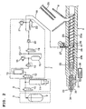
- respective numerals represent the following: 1, injection molding machine; 2, plasticizing cylinder; 3, mold; 4, mold clamping device; 5, carbon dioxide source; 6, carbon dioxide booster; 7, carbon dioxide pressure control; 8, hopper; 9, liquefied carbon dioxide container; 10, electromagnetic on-off valve; 11, liquefied carbon dioxide compressor; 12, electromagnetic on-off valve; 13, heater; 14, reducing valve; 15, main tank; 16, relief valve; 17, meter; 18, gas supply pipe; 19, electromagnetic on-off valve; 20, check valve; 21, relief valve; 22, valve open to the atmosphere; 23, screw; 23a, first stage of the screw; 23b, second stage of the screw; 24, nozzle portion; 25, resin metering device; 26, gas supply section; 27, gas supply channel; 28, flow control section; 29, automatic on-off valve; 30, spring; 31, valve seat; 32, valve shaft; 33, back-flow preventing ring; 34, nozzle hole; 35, needle valve; 36, drive unit; 37, drive rod; 40, back-flow preventing mechanism; 41, first feed section; 42, first complex section; 43, first meter
- the resins to be used in the injection molding method of the invention are thermoplastic resins and specific examples include polyethylene, polypropylene, poly(vinyl chloride), acrylic resins, styrenic resins, poly(ethylene terephthalate), poly(butylene terephthalate), polyallylates, poly(phenylene ether), modified poly(phenylene ether) resins, wholly aromatic polyesters, polyacetals, polycarbonates, amorphous polyolefinic resins, polyetherimide, polyethersulfone, polyamide-based resins, polysulfones, polyetheretherketone, and polyetherketone. These may be used either alone or as a blend of two or more species. They may also be used in the presence of various incorporated fillers and additives.
- Styrenic resins among the above-listed thermoplastic resins are homopolymers and copolymers that use styrene as an essential ingredient, as well as polymer blends prepared from these polymers and other resins; polystyrene and ABS resin are preferred.
- Polystyrene is a styrene homopolymer or a rubber-reinforced polystyrene having rubber distributed in the resin phase.
- thermoplastic resins are those which have high enough affinity for carbon dioxide to be dissolved in large amount, as well as those which can be effectively plasticized with carbon dioxide; particularly preferred are polyethylene, polypropylene, styrenic resins, polyacetals, polycarbonates, poly(phenylene ether) and modified poly(phenylene ether) resins.
- polycarbonates not only permit carbon dioxide to be dissolved in large amount, they also generate carbon dioxide when decomposed thermally; hence, the inclusion of carbon dioxide in the molten resin offers the added advantage of shifting the equilibrium of the decomposition reaction to slow down its rate.
- the injection molding method of the invention is applicable to the production of general injection moldings and can be used to produce not only foamed molded articles but also solid shapes having no cells in the interior.
- the molten resin having gas dissolved therein has a tendency to expand, so in order to prevent the development of a foam pattern on the surface of the molding, the injection molding method of the invention may be combined with the counterpressure method in which the mold cavity is preliminarily pressurized with gas before it is filled with the molten resin so that no foaming occurs in the flow front of the molten resin during cavity filling.
- the gas to be used in the injection molding method of the invention may be exemplified by nitrogen which is commonly used as a blowing gas, inert gases typified by rare gases such as helium and argon, carbon dioxide which is highly soluble in thermoplastic resins and exhibits a satisfactory plasticizer effect, Freons comprising C 1 - C 5 saturated hydrocarbons in which some hydrogen atoms are replaced by fluorine, and the vapors of liquids such as water and alcohols.
- nitrogen which is commonly used as a blowing gas
- inert gases typified by rare gases such as helium and argon
- carbon dioxide which is highly soluble in thermoplastic resins and exhibits a satisfactory plasticizer effect
- Freons comprising C 1 - C 5 saturated hydrocarbons in which some hydrogen atoms are replaced by fluorine
- the vapors of liquids such as water and alcohols.
- carbon dioxide is the most preferred gas. Carbon dioxide has high solubility in molten resin and meets various requirements such as no deterioration of the resin, mold and the constituent material of the molding machine, no hazard to the environment in which molding is performed, and low cost; in addition, if carbon dioxide is used as a plasticizer, it can be rapidly evaporated away from the molded article after molding. If gas is used as a blowing agent, nitrogen having high blowing action is preferred.
- carbon dioxide is used as a plasticizer in the injection molding method of the invention, it is preferably dissolved in the molten resin in an amount of at least 0.2 wt%.
- the maximum amount by which carbon dioxide can be dissolved there is no particular limitation on the maximum amount by which carbon dioxide can be dissolved; however, high gas pressure is needed in order to dissolve a large amount of carbon dioxide and an undue increase in the amount of dissolution simply reduces the effectiveness of carbon dioxide in improving the flowability of the resin; hence, a practical amount of carbon dioxide that may be dissolved is 10 wt% or less, more preferably 5 wt% or less.
- the amount of gas such as carbon dioxide that has dissolved within the plasticizing cylinder is difficult to measure directly, so the difference between the weight of a molded article measured immediately after injection molding of a carbon dioxide containing resin and the weight of the molded article measured after leaving it to stand for at least 24 hours in a hot-air dryer at a temperature about 30 °C lower than the glass transition temperature of the resin if it is amorphous or the melting point of the resin if it is crystalline, until the amount of the carbon dioxide contained in the molded article has leveled off as a result of dissipation is defined as the amount of the carbon dioxide in the molten resin injected into the mold cavity.
- the injection molding machine to be used in the injection molding method of the invention is exemplified by the in-line screw type injection molding machine and the screw preplunger type injection molding machine which are commonly used in injection molding and in which the screw rotates intermittently to plasticate the resin.
- the screw also serves as an injection plunger and with the progress of resin plasticization, the screw retracts to shorten the effective screw length.
- the resin-plasticizing extruder portion is separate from the injection plunger, so the extruder portion can be regarded as a pure extruder.
- the screw preplunger type injection molding machine has fewer limiting factors in screw design and not only is it possible to increase L/D and decrease the root diameter, there is also the advantage of providing ease in keeping gas to be supplied at an optimum position.
- the plasticizing cylinder may have a valve nozzle equipped with a mechanism for opening and closing the nozzle hole.
- This mechanism may be exemplified by a moving needle that opens or closes the nozzle hole or a rotary valve provided in the resin flow channel; a preferred structure opens or closes near the nozzle hole in order to prevent drooling. If an injection molding machine having no valve nozzle is to be used, the escape of the internal pressure can be prevented by using a mold having a hot runner of the valve gate type, with the nozzle portion being pressed onto the mold and the valve gate closed.
- gas may be supplied into the molten resin portion in the plasticizing cylinder so as to form a gas space of a predetermined gas pressure within the plasticizing cylinder in the gas supply section.
- the amount of the gas dissolved in the molten resin varies with the kind of gas, the kind of resin, the temperature of the molten resin, the rotating speed of the screw, the pressure at the front end of the screw, the durations of time for which the screw rotates and remains at rest, etc. but if these conditions are constant, the pressure of the gas in contact with the molten resin is substantially proportional to the amount of the gas dissolved in the molten resin. Therefore, the amount of gas dissolution can be controlled with good reproducibility by forming a gas space in contact with the molten resin and keeping the gas pressure in this gas space at a predetermined level.
- the molten resin is preferably transferred in a starved state through the gas supply section.
- a plasticizing cylinder of a 2-stage type screw is used, with the first stage of the screw comprising, from the rear end side (hopper side), a feed section, a compression section and a metering section, and the second stage of the screw having the same construction, and the resin is melted in the first stage of the screw whereas the feed section of the second stage is used as the gas supply section through which the molten resin is transferred in a starved state, thereby creating an empty space in the plasticizing cylinder and gas is supplied into this empty space so that it is kneaded with the resin in the second stage of the screw and dissolved in the resin.
- the most convenient way to ensure that the molten resin is transferred in a starved state through the gas supply section is by providing a flow control section presenting high resistance to the molten resin in the area between the metering section of the first stage of the screw and the vent portion of the second stage of the screw, thereby limiting the ingress of the molten resin into the second stage of the screw.
- Means for providing the flow control section that presents high resistance to the molten resin include decreasing the channel depth of the screw, special designs for kneading such as Dulmage and Madock, and a simple cylindrical barrier having a clearance of only about 0.1 - 1 mm, preferably 0.1 - 0.5 mm, from the cylinder.
- the above-mentioned flow control section is preferably combined with the practice of transferring more of the molten resin through the second stage of the screw than through the first stage per rotation of the screw.
- a specific technique may be by adopting greater channel pitches and depths in the second stage of the screw than in the first stage.
- the feed section of the second stage (the second feed section) may have a multi-flight (e.g. double flight) screw to reduce the distance between flights; as a result, the pitch can be set at a sufficiently large value to increase the amount of resin transfer; in addition, even if the molten resin is transferred in a starved state, the occurrence of its retention in the screw channels is seldom enough to prevent the resin from being deteriorated due to its retention.
- Another technique that can be combined is by equipping the hopper with a device for metering the resin supply and creating a starved state by controlling the amount of resin supply into the first stage of the screw.
- the molten resin is preferably kneaded with the gas as part of it is allowed to flow backward on the condition.that the starved state is maintained within the second feed section.
- the gas injected into the molten resin can be brought into contact with a sufficiently increased area of the molten resin to promote its dissolution in the molten resin.
- mixing of the portions of molten resin before and after gas injection is sufficiently promoted to suppress uneven dissolution of the gas in the feed direction of the molten resin.
- Part of the molten resin can be caused to flow backward in the above second feed section by forming notches in the screw flights in the second feed section.
- the screw in the second feed section provides a sufficiently large transport, the above-mentioned starved state can be maintained despite this back-flow of the molten resin.
- a kneading effect comparable to that of the back-flow of part of the molten resin in the second feed section can also be obtained by, for example, erecting kneading pins in the second feed section.
- the total area of the notches preferably accounts for 1/50 - 1/2 of the total area of the screw flights in the second feed section, with those notches being distributed over the screw flights in the second feed section. Note that the area of each notch and that of each screw flight are the area of projection in the direction of the central axis of the screw.
- the gas supplied in the gas supply section may pass through the resin in the first stage of the screw to blow out into the hopper and the flow control section is also effective in preventing this phenomenon.
- a moving back-flow preventing mechanism of the same type as commonly used in screw heads can be employed and this may well be called a more positive way.
- the back-flow preventing mechanism Since the function of the back-flow preventing mechanism is to prevent the blowout of gas into the hopper by sealing resin of a comparatively low pressure, it does not need to have a rugged construction and a check ball, a moving ring, a lead valve or a shutter in the form of a spur gear with a limited range of rotation angles can be used; a preferred design is such that as soon as the plasticization process ends, the back-flow preventing mechanism is actuated automatically as by a spring or reverse rotation of the screw.
- the pressure at the front end of the screw is at least equal to the gas pressure in the aforementioned gas space and within a range where the gas space can be maintained within the plasticizing cylinder in the gas supply section.
- the gas supplied into the gas supply section may not be completely dissolved in the molten resin but may partly remain in bubble form so that metering of the molten resin becomes variable or voids occur in the molding; in the latter case, the gas within the voids will expand when the mold is opened and this in turn expands the molding.
- the pressure at the front end of the screw is the pressure of the molten resin at the front end of the screw and this is equal to the back pressure of the screw which pushes the screw or the injection plunger in the direction of injection.
- the following two methods may be employed.
- One of them is a convenient method in which the gas pressure within the gas space in the gas supply section is set to be equal to the pressure at the front end of the screw.
- the lower limit is associated with the plasticization of resin and set to a pressure where the rotation of the screw is proportional to the amount of the plasticized resin; in other words, a minimum pressure at which the screw or the injection plunger retracts at a constant speed given a constant rotating speed of the screw is set as the lower limit.
- the first method can be easily effected by providing the plasticizing cylinder with a pressure sensor which detects the gas pressure within the gas space formed in the gas supply section and by also providing a control unit which controls the pressure at the front end of the screw on the basis of the pressure detected with this pressure sensor.
- the pressure at the front end of the screw can be controlled to become either equal to the pressure in the gas space or greater than it by a predetermined amount.
- the second method is based on the fact that when the gas supplied into the gas supply section partly mixes with the molten resin in bubble form, the apparent amount of molten resin being fed by the screw, namely, the sum of the volumes of the molten resin and the bubbles, increases temporarily, causing the retracting speed of the screw or the injection plunger to increase abruptly.
- the upper limit of the pressure at the front end of the screw is a pressure at which when the resin is plasticized without gas supply, the pressure of the molten resin in the gas supply section becomes equal to the gas supply pressure. If the pressure of the molten resin at the front end of the screw is less than this upper limit, a gas space can exist in the gas supply section and the necessary amount of gas can be dissolved in the molten resin while controlling the amount of its dissolution.
- a gas space can be formed by supplying the gas supply section with a gas having a higher pressure than the molten resin but if the pressure of the molten resin varies, the pressure in the gas space also changes and the amount of the gas dissolved in the molten resin will eventually vary.
- the transfer of the molten resin through the gas supply section is always held in a starved state irrespective of gas supply, thereby ensuring that the pressure of the molten resin in the gas supply section is kept subatmospheric. In this case, the gas space in the gas supply section will not be compressed by the molten resin and the amount of gas to be dissolved in the molten resin can be controlled by the pressure of gas being supplied into the gas supply section.
- the absolute value of the pressure at the front end of the screw (back pressure of the screw) varies with the size of screw, its design, its rotating speed, the kind of resin, its temperature, the pressure of gas to be supplied, etc. but it is at least equal to the pressure of gas to be supplied into the gas supply section and selected within a range where the pressure of the molten resin in the gas supply section is less than the pressure of gas being supplied into the gas supply section.
- the molten resin with dissolved gas has a tendency to expand, so in order to suppress the occurrence of foaming during shutdown of the screw after the end of plasticization until injection starts, the above-described pressure at the front end of the screw is desirably retained.
- the pressure to be retained at the front end of the screw may be equal to the pressure at the front end of the screw that is applied during resin plasticization and may be a minimum pressure at which the screw or plunger will not retract upon expansion of the molten resin. If the pressure at the front end of the screw which is to be retained after the end of plasticization until injection starts is unduly high, the screw or plunger will have advanced before the injection process starts, causing an error in the amount of molten resin that was metered during plasticization. Even in the case of suspending the molding process for a short time, the pressure at the front end of the screw is preferably retained at a non-screw or plunger retracting level in order to prevent foaming of the residual molten resin in the plasticizing cylinder.
- a technique by which the pressure at the front end of the screw can be maintained constant during shutdown of the screw is one of maintaining a constant force for advancing the screw and in the case where the screw is advanced by hydraulic drive, this can be accomplished by maintaining the screw advancing hydraulic force constant.
- the desired effect can also be obtained by closing a screw advancing hydraulic valve during screw shutdown to cut the flow of a working oil countering the pressure at the front end of the screw, thus locking the screw against retraction.
- Control may also be effected to maintain the position of the screw or plunger constant and this is suitable for the case where the screw is advanced by drive with an electric motor.
- the supply of gas into the plasticizing cylinder in the gas supply section is preferably effected via an automatic on-off valve that is opened and closed automatically by the pressure difference between the supply pressure and the pressure within the cylinder in the gas supply section.
- Such automatic on-off valve include a mushroom valve (a valve body in the form of a frustum, typically a frustum of a cone) that is provided at the distal end of a gas supply channel open to the interior of the plasticizing cylinder in the gas supply section such that it is urged by a spring in a direction where it makes intimate contact with the valve seat and which, when pushed by the pressure of gas being supplied, counters the spring and moves into the plasticizing cylinder to open the gas supply channel.
- a mushroom valve a valve body in the form of a frustum, typically a frustum of a cone
- the gas supply channel is opened in a gas supply mode in accordance with the gas flow to provide a comparatively large area of opening and, hence, the necessary amount of gas can be supplied within a short time.
- the apparatus of this example uses an in-line screw type injection molding machine and carbon dioxide as a gas.
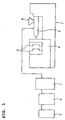
- numeral 1 designates an injection molding machine which is furnished with a plasticizing cylinder 2 which plasticates and injects a thermoplastic resin, a mold 3 and a mold clamping device 4.
- the plasticizing cylinder 2 in the injection molding machine 1 is supplied with carbon dioxide from a carbon dioxide source 5 via a gas supply device comprising a carbon dioxide booster 6 and a carbon dioxide pressure control 7.
- carbon dioxide may be supplied into the mold 3 and used as a gas to produce counterpressure; alternatively, it may be supplied into a hopper 8 on the plasticizing cylinder 2 so that it is absorbed by a resin being supplied from the hopper 8 into the plasticizing cylinder 2.
- the carbon dioxide to be supplied into the plasticizing cylinder 2, the carbon dioxide to be supplied into the mold 3 and the carbon dioxide to be supplied into the hopper 8 are preferably adapted to be controllable independently in such terms as the start and stop of supply and the supply pressure.
- a liquefied carbon dioxide container 9 is used as the carbon dioxide source 5 in the case under consideration.
- the carbon dioxide booster 6 is equipped with a liquefied carbon dioxide compressor 11 which pressurizes liquefied carbon dioxide to have an elevated pressure and the liquefied carbon dioxide container 9 is connected to the liquefied carbon dioxide compressor 11 via an electromagnetic on-off valve 10.
- the space between the carbon dioxide source 5 and the carbon dioxide booster 6 is held below the critical temperature of carbon dioxide (31.1 °C) in order to keep the carbon dioxide liquefied.
- the liquefied carbon dioxide supplied into the liquefied carbon dioxide compressor 11 from the liquefied carbon dioxide container 9 and which has been compressed there to have a higher pressure is sent to the carbon dioxide pressure control 7.
- the liquefied carbon dioxide sent to the carbon dioxide pressure control 7 is supplied to a heater 13 via an electromagnetic on-off valve 12.
- the liquefied carbon dioxide supplied into the heater 13 is heated there to become a gas hotter than the critical temperature and the gas passes through a reducing valve 14 to be supplied into a main tank 15 for the plasticizing cylinder 2.
- the main tank 15 is connected to a relief valve 16 for escape of gas if the internal pressure becomes abnormally high and a meter 17 for checking the gas pressure in the main tank 15.
- the above main tank 15 and the plasticizing cylinder 2 are connected by a gas supply pipe 18 which are equipped, in order from the main tank 15, with an electromagnetic on-off valve 19 and a check valve 20.
- a relief valve 21 and a valve 22 open to the atmosphere.
- the electromagnetic on-off valve 10 is opened with the electromagnetic on-off valves 19 and 20 closed, whereupon liquefied carbon dioxide is supplied from the liquefied carbon dioxide container 9 into the liquefied carbon dioxide compressor 11.
- the electromagnetic on-off valve 12 Upon opening the electromagnetic on-off valve 12, the liquefied carbon dioxide gas compressed in the liquefied carbon dioxide compressor 11 is supplied into the heater 13 and warmed, then its pressure is reduced to the necessary level by the reducing valve 12 before it is stored in the main tank 15.
- the electromagnetic on-off valve 19 is opened and a predetermined pressure of carbon dioxide is supplied into the plasticizing cylinder 2 via the gas supply pipe 18.
- the plasticizing cylinder 2 is equipped with a 2-stage type screw 23 in which a stage comprising, in order from the resin supply section toward the front end, a feed section, a compression section and a metering section is repeated twice in series and the first stage of the screw 23a is closer to the hopper 8 and the second stage of the screw 23b is closer to the nozzle portion 24.
- the first stage of the screw 23a comprises a first feed section 41, a first compression section 42 and a first metering section 43 and similarly the second stage of the screw 23b comprises a second feed section 44, a second compression section 45 and a second metering section 46.
- a flow control section 28 is provided between the gas supply section 26 and the first stage of the screw 23a.
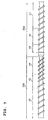
- Fig. 3 shows enlarged an example of the flow control section.
- the flow control section 28 has a small clearance t from the inner surface of the barrel of the plasticizing cylinder 2 and controls the amount of the molten resin being transferred from the first stage of the screw 23a to ensure that the molten resin is transferred in a starved state through the gas supply section 26 and that the carbon dioxide supplied into the gas supply section 26 will not flow backward to the hopper 8. If a mechanism for preventing the back-flow of the molten resin is to be provided, it is installed between the flow control section 28 and the gas supply section 26 (see a back-flow preventing mechanism 40 in Fig. 1) and, depending on the screw design, the flow control section 28 may be omitted.
- the clearance t between the flow control section 28 and the inner surface of the barrel of the plasticizing cylinder 2 is variable with the screw diameter but it is preferably about 0.1 - 1 mm, more preferably about 0.1 - 0.5 mm.
- the length 1 of the flow control section 28 is preferably about 5 - 200% of the screw diameter, more preferably about 10 - 100% of the screw diameter.
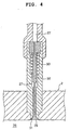
- the molten resin is transferred in a starved state through the gas supply section 26 by means of the above flow control section 28 and the empty space thus formed in the gas supply section 26 (the area not filled with the molten resin) is supplied with carbon dioxide via an automatic on-off valve 29 shown in Fig. 4.
- the automatic on-off valve 29 in the case under consideration comprises a mushroom valve which is urged outward of the injection cylinder 2 by means of a spring 30 so that it is pressed onto a valve seat 31.
- the front end portion of the screw 23 is provided with a back-flow preventing mechanism 33 for preventing the molten resin from flowing backward when it is being injected.
- the back-flow preventing mechanism 33 may be as shown in Fig. 9; a small-diameter portion 60 is formed in the front end portion of the screw 23 and an annular check ring 62 is inserted into the small-diameter portion 60, with a resin flow channel 61 left between the ring 62 and the outer peripheral surface of the small-diameter portion 60, in such a way that the ring 62 is capable of moving along the central axis of the screw 23, and a spring 63 is provided to press the check ring 62 toward the rear end (toward the hopper 8).
- the injection molding method of the invention can be performed with the same apparatus even if gases other than carbon dioxide are used.
- Rubber-reinforced polystyrene A&M POLYSTYRENE.492, product of A&M Styrene Co.
- the pressure of carbon dioxide supplied to the gas supply section is proportional to the amount of carbon dioxide dissolved in the molten resin and it is seen that the amount of carbon dioxide dissolved in the molten resin can be controlled by the pressure of carbon dioxide.
- a screw containing notches in the second feed section and a rubber reinforced polystyrene resin were used; the temperature of the plasticizing cylinder was set at 210 °C and 30 purging actions were performed with the screw rotating at 150 rpm, with a pressure of 10 MPa being exerted at the front end of the screw and with 10 MPa of carbon dioxide being supplied into the gas supply section.
- the strand from the nozzle portion foamed finely but it did not break nor was heard any sound of bursting bubbles; it was therefore speculated that no large bubbles existed in the molten resin.
- a screw containing notches in the second feed section and a rubber reinforced polystyrene resin were used; the temperature of the plasticizing cylinder was set at 210 °C, the screw was rotating at 150 rpm and a pressure of 30 MPa being exerted at the front end of the screw.
- a pressure, of 12 MPa was detected for the molten resin, indicating that the gas supply section was filled with the molten resin.
- Molding was performed without pressurizing the cavity with carbon dioxide.
- the moldings were clear and had no foam patterns on the surface.
- the amount of carbon dioxide dissolved in the molten resin as obtained from the decrease in the weight of the moldings was no more than 0.1 wt%.
- injection molding was performed using a rubber reinforced polystyrene.
- the pressure of carbon dioxide being supplied to the gas supply section was held at 9 MPa, the screw was rotating at 150 rpm, a pressure of 11 MPa was exerted at the front end of the screw, and a counterpressure produced by 7 MPa of carbon dioxide was applied in order to prevent foaming from occurring while the mold was in the process of filling with the molten resin.
- a counterpressure produced by 7 MPa of carbon dioxide was applied in order to prevent foaming from occurring while the mold was in the process of filling with the molten resin.
- two types of screw one containing notches in the screw flights in the second feed section and the other containing no notches, molding was performed with the molding cycle time varied over the range of from 26 to 100 seconds in each case.
- Fig. 10 shows, when the screw containing notches in the screw flights in the second feed section was used, the dissolution of carbon dioxide increased by a factor of 1.5 compared to the case of using the screw containing no such notches, indicating that an increased amount of carbon oxide could be dissolved.
- the screw containing notches in the screw flights in the second feed section was used, the fluctuation in the amount of dissolved carbon dioxide due to the fluctuation in the molding cycle time was small compared to the case of using the screw containing no such notches, indicating the possibility of performing more consistent molding.
- the amount of carbon dioxide dissolved in the molten resin was measured as in Example 3, except that the resin to be used was changed to PMMA.
- the experiment was done using a screw containing notches in the screw flights in the second feed section and a screw containing no such notches.
- Fig. 11 shows the relationship between the molding cycle time and the amount of carbon dioxide dissolved in the molten resin, provided that the vertical axis plots the amount of carbon dioxide for each molding cycle time in terms of ratio, with the amount of carbon dioxide being taken as unity for the case where the molding cycle time was 100 seconds.
- Fig. 11 shows, when the screw containing notches in the screw flights in the second feed section was used, more carbon dioxide could be dissolved than in the case of using the screw containing no such notches.
- the fluctuation in the amount of dissolved carbon dioxide due to the fluctuation in the molding cycle time was small compared to the case of using the screw containing no such notches, indicating the possibility of performing more consistent molding.
- the present invention is as described on the foregoing pages; the necessary amount of gas can be dissolved in molten resin with good reproducibility in a quantitative manner; on account of the notches made in the screw, gas of low enough pressure can be dissolved in a greater amount in the molten resin to perform injection molding; as a result, injection molding which has gas dissolved in the molten resin to improve its flowability, as well as foam molding using a dissolved gas can be performed efficiently.
- the fluctuation in the amount of dissolved gas that accompanies the fluctuation in the molding cycle time can be sufficiently reduced to enable consistent injection molding.
Landscapes
- Engineering & Computer Science (AREA)
- Manufacturing & Machinery (AREA)
- Mechanical Engineering (AREA)
- Injection Moulding Of Plastics Or The Like (AREA)
Abstract
Description
wherein said plasticizing cylinder has a multi-stage type screw in which a stage comprising, in the following order from the rear end side toward the front end side in the direction of injection, a feed section, a compression section and a metering section is repeated a plurality of times in series, and which is also equipped with a gas supply channel open to the feed section of the front end side screw stage, and
wherein said supply device is connected to the gas supply channel.
Claims (16)
- An injection molding method comprising supplying a gas into a molten resin in a plasticizing cylinder and injecting the molten resin having the gas dissolved therein, wherein when the resin is being plasticized, a gas space with a predetermined gas pressure is formed within the plasticizing cylinder in a gas supply section and the pressure at the front end of a screw is adjusted to be at least equal to the gas pressure in the gas space and within a range where the gas space can be maintained within the plasticizing cylinder in the gas supply section.
- The injection molding method according to claim 1, wherein the gas pressure in the gas space formed in the gas supply section is detected and the pressure at the front end of the screw is controlled on the basis of this gas pressure.
- The injection molding method according to claim 1, wherein the molten resin is transferred in a starved state within the gas supply section.
- The injection molding method according to claim 1, wherein the pressure at the front end of the screw exerted during plasticization is also retained during the screw shutdown period from the end of plasticization to the start of injection.
- The injection molding method according to claim 1, wherein the gas is carbon dioxide.
- The injection molding method according to claim 1, wherein the plasticizing cylinder is equipped with a multi-stage type screw in which a stage comprising, in the following order from the resin supply section side toward the front end side of the screw, a feed section, a compression section and a metering section is repeated a plurality of times in series, and the gas supply section is located within the feed section of the front end side screw stage.
- The injection molding method according to claim 6, wherein notches are formed in the screw flights in the feed section of the front end side screw stage, and the gas and the molten resin are kneaded to dissolve the gas into the molten resin while part of the molten resin is caused to flow backward by means of said notches.
- The injection molding method according to claim 6, wherein a flow control section presenting high resistance to the flow of the molten resin is provided in the metering section of the rear end side screw stage of the plasticizing cylinder.
- The injection molding method according to claim 6, wherein the plasticizing cylinder is equipped with a mechanism for preventing a back-flow of the molten resin in the metering section of the rear end side screw stage.
- The injection molding method according to claim 1, wherein the gas supply into the plasticizing cylinder in the gas supply section is effected via an automatic on-off valve which is pressed by a spring onto a valve seat provided on the perimeter of an opening in a gas supply channel that extends into the plasticizing cylinder and which, when gas is supplied into the gas supply channel, is pushed against the spring by the pressure difference between the supply pressure and the pressure within the cylinder in the gas supply section and moved into the plasticizing cylinder to open the gas supply channel.
- The injection molding method according to claim 1, wherein an in-line screw type injection molding machine is used, said molding machine being equipped with a valve nozzle having a closable injection port and a mechanism provided at the front end of the screw to prevent back-flow of the molten resin, wherein the screw is rotated with the injection port being closed, and as soon as a predetermined amount of the molten resin with dissolved carbon dioxide is accumulated in the front part of the plasticizing cylinder, the resin back-flow preventing mechanism in the front end portion of the screw is brought to closure with the back pressure of the screw being maintained near the position where the screw completes metering, and then the injection port is opened to inject the molten resin.
- An injection molding apparatus which comprises a plasticizing cylinder and a gas supply device for supplying a gas into a molten resin in the plasticizing cylinder and which injects the molten resin having the gas dissolved therein,
wherein said plasticizing cylinder has a multi-stage type screw in which a stage comprising, in the following order from the rear end side toward the front end side in the direction of injection, a feed section, a compression section and a metering section is repeated a plurality of times in series, and which is also equipped with a gas supply channel open to the feed section of the front end side screw stage, and
wherein said gas supply device is connected to the gas supply channel. - The injection molding apparatus according to claim 12, further comprising a pressure sensor for detecting the pressure of the gas supplied into the plasticizing cylinder via the gas supply channel and a control unit for controlling the pressure at the front end of the screw on the basis of the pressure as detected with said sensor.
- The injection molding apparatus according to claim 12, further comprising an automatic on-off valve, which is pressed by a spring onto a valve seat provided on the perimeter of an opening in the gas supply channel that extends into the plasticizing cylinder and which, when gas is supplied into the gas supply channel, is pushed against the spring by the pressure difference between the supply pressure and the pressure within the cylinder in the gas supply section and moved into the plasticizing cylinder to open the, gas supply channel.
- The injection molding apparatus according to claim 12, wherein screw flights in the feed section of the front end side screw stage contain notches.
- The injection molding apparatus according to claim 12, wherein a flow control section presenting high resistance to the flow of the molten resin is provided in the metering section of the rear end side screw stage.
Applications Claiming Priority (3)
| Application Number | Priority Date | Filing Date | Title |
|---|---|---|---|
| JP2000161640 | 2000-05-31 | ||
| JP2000161640 | 2000-05-31 | ||
| PCT/JP2001/004622 WO2001091987A1 (en) | 2000-05-31 | 2001-05-31 | Injection molding method |
Publications (2)
| Publication Number | Publication Date |
|---|---|
| EP1293319A1 true EP1293319A1 (en) | 2003-03-19 |
| EP1293319A4 EP1293319A4 (en) | 2006-05-24 |
Family
ID=18665637
Family Applications (1)
| Application Number | Title | Priority Date | Filing Date |
|---|---|---|---|
| EP01934470A Withdrawn EP1293319A4 (en) | 2000-05-31 | 2001-05-31 | Injection molding method |
Country Status (4)
| Country | Link |
|---|---|
| US (1) | US6929763B2 (en) |
| EP (1) | EP1293319A4 (en) |
| CN (1) | CN1380848A (en) |
| WO (1) | WO2001091987A1 (en) |
Cited By (1)
| Publication number | Priority date | Publication date | Assignee | Title |
|---|---|---|---|---|
| EP2746025A4 (en) * | 2011-08-19 | 2015-02-25 | Hitachi Maxell | KNEE DEVICE, METHOD FOR PRODUCING A HEAT-RESISTANT RESIN BODY AND INJECTION MOLDING METHOD |
Families Citing this family (30)
| Publication number | Priority date | Publication date | Assignee | Title |
|---|---|---|---|---|
| US7897092B2 (en) * | 2005-05-30 | 2011-03-01 | Shinsei Kagaku Co., Ltd. | Method for producing non-foamed molded body |
| JP4839728B2 (en) * | 2005-08-25 | 2011-12-21 | 宇部興産機械株式会社 | Thermoplastic resin multilayer molding method and multilayer molding apparatus |
| US7767119B2 (en) * | 2005-09-29 | 2010-08-03 | Plakor Co., Ltd. | Gas injecting device of cylinder for injection molding machine, and method for controlling amount of gas injected into barrel of injection molding machine |
| JP4797661B2 (en) * | 2006-02-02 | 2011-10-19 | マツダ株式会社 | Method and apparatus for molding fiber reinforced resin molded product |
| JP4867374B2 (en) * | 2006-02-02 | 2012-02-01 | マツダ株式会社 | Fiber reinforced resin molded product molding equipment |
| JP5021572B2 (en) * | 2008-06-19 | 2012-09-12 | 本田技研工業株式会社 | Production equipment and production method for industrial products |
| US20100013130A1 (en) * | 2008-07-18 | 2010-01-21 | Dell Products L.P. | Molding Method For Thin Parts |
| JP5070152B2 (en) * | 2008-07-28 | 2012-11-07 | 日立マクセル株式会社 | Manufacturing method of resin molding |
| US20110215496A1 (en) * | 2010-03-04 | 2011-09-08 | Fujifilm Corporation | Injection molding method |
| JP5683940B2 (en) * | 2010-12-22 | 2015-03-11 | 住友重機械工業株式会社 | Plasticizing equipment |
| DE102011105772B4 (en) * | 2011-06-24 | 2014-10-30 | Wittmann Battenfeld Gmbh | Device for injection molding of plastic molded parts made of thermoplastic material |
| JP5823015B2 (en) * | 2014-12-24 | 2015-11-25 | 日立マクセル株式会社 | Kneading apparatus and method for producing thermoplastic resin molded body |
| JP6385855B2 (en) * | 2015-02-26 | 2018-09-05 | 住友重機械工業株式会社 | Injection device |
| JP6139038B1 (en) * | 2015-07-08 | 2017-05-31 | 日立マクセル株式会社 | Method for producing foam molded article |
| CN112060457B (en) * | 2016-03-15 | 2022-04-26 | 麦克赛尔株式会社 | Apparatus for manufacturing foam molded body, screw of injection molding apparatus, and injection molding apparatus |
| JP6211664B1 (en) * | 2016-10-05 | 2017-10-11 | 株式会社日本製鋼所 | Injection molding machine screw and injection molding machine |
| JP6777553B2 (en) * | 2017-01-11 | 2020-10-28 | マクセル株式会社 | Manufacturing method and manufacturing equipment for foam molded products |
| CN110014535B (en) * | 2017-07-12 | 2021-06-29 | 张再顺 | Quick Die Changer for Molding Machines |
| JP6570582B2 (en) * | 2017-07-21 | 2019-09-04 | 株式会社日本製鋼所 | Injection molding machine for foam molding |
| JP7101471B2 (en) * | 2017-12-08 | 2022-07-15 | マクセル株式会社 | Manufacturing method and manufacturing equipment for foam molded products |
| JP7128015B2 (en) * | 2018-04-09 | 2022-08-30 | マクセル株式会社 | Manufacturing method and manufacturing apparatus for foam molded product |
| AT521522B1 (en) * | 2018-08-10 | 2021-07-15 | Japan Steel Works Ltd | Injection device for foam molding and molding method for foamed molded article |
| CN109519579B (en) * | 2018-12-26 | 2025-01-03 | 万通(苏州)定量阀系统有限公司 | valve |
| CN111376498A (en) * | 2018-12-27 | 2020-07-07 | 中材科技风电叶片股份有限公司 | Pouring process and forming method of wind power blade |
| CN109551734B (en) * | 2019-01-22 | 2023-11-03 | 华域视觉科技(上海)有限公司 | Injection device and injection system |
| CN112776246B (en) * | 2019-11-11 | 2023-01-17 | 株式会社沙迪克 | Injection device and gas dissolving method for injection device |
| JP7463261B2 (en) * | 2020-12-10 | 2024-04-08 | 株式会社日本製鋼所 | Injection molding machine for performing foam molding and method for controlling the injection molding machine |
| JP7604328B2 (en) * | 2021-06-14 | 2024-12-23 | 株式会社日本製鋼所 | Injection molding machine for foam molding |
| CN115320052A (en) * | 2022-07-21 | 2022-11-11 | 贵州省材料产业技术研究院 | Injection molding machine and injection molding method for manufacturing low-odor high-quality foaming parts |
| CN117160357B (en) * | 2023-09-05 | 2026-03-06 | 贵港双胞胎星顺饲料有限公司 | An extruded pellet feed processing equipment |
Family Cites Families (24)
| Publication number | Priority date | Publication date | Assignee | Title |
|---|---|---|---|---|
| DE2034310A1 (en) * | 1970-07-10 | 1972-01-13 | Desma Werke Gmbh | Process for the production of an injectable, foamable material for the manufacture of foamed objects and a screw injection molding machine for the implementation of the process |
| US3856442A (en) * | 1970-10-19 | 1974-12-24 | Ici Ltd | Dispersion of materials in thermoplastics |
| US3787542A (en) * | 1971-10-14 | 1974-01-22 | Ici Ltd | Production of extruded foamed synthetic thermoplastic polymeric materials |
| US3986709A (en) * | 1973-07-19 | 1976-10-19 | Shell Oil Company | Direct gassing extruder with gas pockets |
| GB1485587A (en) * | 1974-01-22 | 1977-09-14 | Furukawa Electric Co Ltd | Process of producing a foamed thermoplastics resin articl |
| JPS5420467Y2 (en) * | 1974-06-06 | 1979-07-24 | ||
| US4043715A (en) * | 1975-06-02 | 1977-08-23 | Ex-Cell-O Corporation | Pumped injection of gas for making foamed plastic |
| US4134714A (en) * | 1977-04-18 | 1979-01-16 | General Electric Company | Multi-stage continuous plastic extrusion apparatus, and extrusion screw |
| US4185060A (en) * | 1978-03-17 | 1980-01-22 | Ladney M Jr | Method of manufacturing structural foam plastic products free from undesirable contaminant constituents |
| US4211523A (en) * | 1978-11-29 | 1980-07-08 | Hoover Universal, Inc. | Gas-flow control apparatus for equipment for producing foamed plastic |
| US4426427A (en) * | 1982-07-19 | 1984-01-17 | Vieth Wolf R | Saturated preform and method for preparation thereof |
| JPS60220724A (en) * | 1984-04-17 | 1985-11-05 | Nissei Plastics Ind Co | Preplasticizing apparatus |
| JPH0420467Y2 (en) | 1985-07-31 | 1992-05-11 | ||
| US4733970A (en) * | 1985-09-09 | 1988-03-29 | Sterling Extruder Corporation | Extruder screw |
| US5098267A (en) * | 1990-06-22 | 1992-03-24 | Union Carbide Industrial Gases Technology Corporation | Apparatus and method for producing and molding structural foam |
| US5158986A (en) * | 1991-04-05 | 1992-10-27 | Massachusetts Institute Of Technology | Microcellular thermoplastic foamed with supercritical fluid |
| JPH09323338A (en) * | 1996-06-05 | 1997-12-16 | Hitachi Ltd | Injection molding method and apparatus for foam molded article |
| GB2338925B (en) * | 1997-04-02 | 2002-02-20 | Coraltech Ltd | Gas introduction |
| CN1101748C (en) | 1997-05-21 | 2003-02-19 | 旭化成株式会社 | Method for injection molding of thermoplastic resins |
| JP3211946B2 (en) * | 1997-07-22 | 2001-09-25 | 株式会社新潟鉄工所 | Injection molding machine for foam molding |
| US6303666B1 (en) * | 1998-07-30 | 2001-10-16 | Mitsui Chemicals, Inc. | Process for the production of expanded olefinic thermoplastic elastomer products |
| DE19848151C2 (en) * | 1998-10-20 | 2002-09-19 | Battenfeld Gmbh | Method and device for injection molding of plastic molded parts made of thermoplastic |
| JP4276752B2 (en) * | 1999-10-22 | 2009-06-10 | 株式会社日本製鋼所 | Method for molding thermoplastic resin foam |
| US6602063B1 (en) * | 2000-07-21 | 2003-08-05 | Trexel, Inc. | Discontinuous blowing agent delivery system and method |
-
2001
- 2001-05-31 US US10/048,529 patent/US6929763B2/en not_active Expired - Lifetime
- 2001-05-31 EP EP01934470A patent/EP1293319A4/en not_active Withdrawn
- 2001-05-31 WO PCT/JP2001/004622 patent/WO2001091987A1/en not_active Ceased
- 2001-05-31 CN CN01801519.0A patent/CN1380848A/en active Pending
Cited By (3)
| Publication number | Priority date | Publication date | Assignee | Title |
|---|---|---|---|---|
| EP2746025A4 (en) * | 2011-08-19 | 2015-02-25 | Hitachi Maxell | KNEE DEVICE, METHOD FOR PRODUCING A HEAT-RESISTANT RESIN BODY AND INJECTION MOLDING METHOD |
| US9186634B2 (en) | 2011-08-19 | 2015-11-17 | Hitachi Maxell, Ltd. | Kneading apparatus, method for producing thermoplastic resin molded product, and foam injection molding method |
| US9718217B2 (en) | 2011-08-19 | 2017-08-01 | Hitachi Maxell, Ltd. | Kneading apparatus, method for producing thermoplastic resin molded product, and foam injection molding method |
Also Published As
| Publication number | Publication date |
|---|---|
| EP1293319A4 (en) | 2006-05-24 |
| US6929763B2 (en) | 2005-08-16 |
| CN1380848A (en) | 2002-11-20 |
| WO2001091987A1 (en) | 2001-12-06 |
| US20030011090A1 (en) | 2003-01-16 |
Similar Documents
| Publication | Publication Date | Title |
|---|---|---|
| US6929763B2 (en) | Injection molding method | |
| JP6522701B2 (en) | Production device for foam molding | |
| JP6843919B2 (en) | Screw of injection molding equipment and injection molding equipment | |
| US6884380B2 (en) | Method of injection molding of thermoplastic resin | |
| EP1621312A2 (en) | Thermoplastic resin foam product | |
| WO1998052734A1 (en) | Method for injection molding of thermoplastic resins | |
| JP2002540979A (en) | Method for producing a foam material including a system having a pressure limiting element | |
| JP6055710B2 (en) | Vent-up detection mechanism, vent-up prevention device, molded body manufacturing method, and molded body molding apparatus | |
| US6652254B2 (en) | Molding apparatus including screw for molded articles of thermoplastic gas impregnated resin | |
| US11820063B2 (en) | Manufacturing method and manufacturing device for foam molded article | |
| JP2001341152A (en) | Injection molding equipment | |
| JP2004237522A (en) | Injection molding equipment | |
| JP6474330B2 (en) | Injection molding method | |
| JP3851439B2 (en) | Manufacturing method of difficult-to-mold resin molded products | |
| JPWO2001091987A1 (en) | injection molding method | |
| JP7128015B2 (en) | Manufacturing method and manufacturing apparatus for foam molded product | |
| JPWO2001096084A1 (en) | Thermoplastic resin injection molding |
Legal Events
| Date | Code | Title | Description |
|---|---|---|---|
| PUAI | Public reference made under article 153(3) epc to a published international application that has entered the european phase |
Free format text: ORIGINAL CODE: 0009012 |
|
| 17P | Request for examination filed |
Effective date: 20020222 |
|
| AK | Designated contracting states |
Kind code of ref document: A1 Designated state(s): AT BE CH CY DE DK ES FI FR GB GR IE IT LI LU MC NL PT SE TR Designated state(s): AT BE CH CY DE DK ES FI FR GB GR IE IT LI LU MC NL PT SE TR |
|
| AX | Request for extension of the european patent |
Extension state: AL LT LV MK RO SI |
|
| A4 | Supplementary search report drawn up and despatched |
Effective date: 20060407 |
|
| STAA | Information on the status of an ep patent application or granted ep patent |
Free format text: STATUS: THE APPLICATION HAS BEEN WITHDRAWN |
|
| 18W | Application withdrawn |
Effective date: 20081002 |