JP6777553B2 - Manufacturing method and manufacturing equipment for foam molded products - Google Patents
Manufacturing method and manufacturing equipment for foam molded products Download PDFInfo
- Publication number
- JP6777553B2 JP6777553B2 JP2017002896A JP2017002896A JP6777553B2 JP 6777553 B2 JP6777553 B2 JP 6777553B2 JP 2017002896 A JP2017002896 A JP 2017002896A JP 2017002896 A JP2017002896 A JP 2017002896A JP 6777553 B2 JP6777553 B2 JP 6777553B2
- Authority
- JP
- Japan
- Prior art keywords
- foaming agent
- introduction
- molten resin
- physical foaming
- adjusting container
- Prior art date
- Legal status (The legal status is an assumption and is not a legal conclusion. Google has not performed a legal analysis and makes no representation as to the accuracy of the status listed.)
- Active
Links
Images
Classifications
-
- B—PERFORMING OPERATIONS; TRANSPORTING
- B29—WORKING OF PLASTICS; WORKING OF SUBSTANCES IN A PLASTIC STATE IN GENERAL
- B29C—SHAPING OR JOINING OF PLASTICS; SHAPING OF MATERIAL IN A PLASTIC STATE, NOT OTHERWISE PROVIDED FOR; AFTER-TREATMENT OF THE SHAPED PRODUCTS, e.g. REPAIRING
- B29C44/00—Shaping by internal pressure generated in the material, e.g. swelling or foaming ; Producing porous or cellular expanded plastics articles
- B29C44/34—Auxiliary operations
- B29C44/3442—Mixing, kneading or conveying the foamable material
- B29C44/3446—Feeding the blowing agent
-
- B—PERFORMING OPERATIONS; TRANSPORTING
- B29—WORKING OF PLASTICS; WORKING OF SUBSTANCES IN A PLASTIC STATE IN GENERAL
- B29C—SHAPING OR JOINING OF PLASTICS; SHAPING OF MATERIAL IN A PLASTIC STATE, NOT OTHERWISE PROVIDED FOR; AFTER-TREATMENT OF THE SHAPED PRODUCTS, e.g. REPAIRING
- B29C44/00—Shaping by internal pressure generated in the material, e.g. swelling or foaming ; Producing porous or cellular expanded plastics articles
- B29C44/34—Auxiliary operations
-
- B—PERFORMING OPERATIONS; TRANSPORTING
- B29—WORKING OF PLASTICS; WORKING OF SUBSTANCES IN A PLASTIC STATE IN GENERAL
- B29C—SHAPING OR JOINING OF PLASTICS; SHAPING OF MATERIAL IN A PLASTIC STATE, NOT OTHERWISE PROVIDED FOR; AFTER-TREATMENT OF THE SHAPED PRODUCTS, e.g. REPAIRING
- B29C44/00—Shaping by internal pressure generated in the material, e.g. swelling or foaming ; Producing porous or cellular expanded plastics articles
- B29C44/02—Shaping by internal pressure generated in the material, e.g. swelling or foaming ; Producing porous or cellular expanded plastics articles for articles of definite length, i.e. discrete articles
-
- B—PERFORMING OPERATIONS; TRANSPORTING
- B29—WORKING OF PLASTICS; WORKING OF SUBSTANCES IN A PLASTIC STATE IN GENERAL
- B29C—SHAPING OR JOINING OF PLASTICS; SHAPING OF MATERIAL IN A PLASTIC STATE, NOT OTHERWISE PROVIDED FOR; AFTER-TREATMENT OF THE SHAPED PRODUCTS, e.g. REPAIRING
- B29C44/00—Shaping by internal pressure generated in the material, e.g. swelling or foaming ; Producing porous or cellular expanded plastics articles
- B29C44/20—Shaping by internal pressure generated in the material, e.g. swelling or foaming ; Producing porous or cellular expanded plastics articles for articles of indefinite length
-
- B—PERFORMING OPERATIONS; TRANSPORTING
- B29—WORKING OF PLASTICS; WORKING OF SUBSTANCES IN A PLASTIC STATE IN GENERAL
- B29C—SHAPING OR JOINING OF PLASTICS; SHAPING OF MATERIAL IN A PLASTIC STATE, NOT OTHERWISE PROVIDED FOR; AFTER-TREATMENT OF THE SHAPED PRODUCTS, e.g. REPAIRING
- B29C44/00—Shaping by internal pressure generated in the material, e.g. swelling or foaming ; Producing porous or cellular expanded plastics articles
- B29C44/34—Auxiliary operations
- B29C44/36—Feeding the material to be shaped
- B29C44/38—Feeding the material to be shaped into a closed space, i.e. to make articles of definite length
- B29C44/42—Feeding the material to be shaped into a closed space, i.e. to make articles of definite length using pressure difference, e.g. by injection or by vacuum
- B29C44/422—Feeding the material to be shaped into a closed space, i.e. to make articles of definite length using pressure difference, e.g. by injection or by vacuum by injecting by forward movement of the plastizising screw
-
- B—PERFORMING OPERATIONS; TRANSPORTING
- B29—WORKING OF PLASTICS; WORKING OF SUBSTANCES IN A PLASTIC STATE IN GENERAL
- B29C—SHAPING OR JOINING OF PLASTICS; SHAPING OF MATERIAL IN A PLASTIC STATE, NOT OTHERWISE PROVIDED FOR; AFTER-TREATMENT OF THE SHAPED PRODUCTS, e.g. REPAIRING
- B29C44/00—Shaping by internal pressure generated in the material, e.g. swelling or foaming ; Producing porous or cellular expanded plastics articles
- B29C44/34—Auxiliary operations
- B29C44/36—Feeding the material to be shaped
- B29C44/46—Feeding the material to be shaped into an open space or onto moving surfaces, i.e. to make articles of indefinite length
- B29C44/50—Feeding the material to be shaped into an open space or onto moving surfaces, i.e. to make articles of indefinite length using pressure difference, e.g. by extrusion or by spraying
-
- B—PERFORMING OPERATIONS; TRANSPORTING
- B29—WORKING OF PLASTICS; WORKING OF SUBSTANCES IN A PLASTIC STATE IN GENERAL
- B29C—SHAPING OR JOINING OF PLASTICS; SHAPING OF MATERIAL IN A PLASTIC STATE, NOT OTHERWISE PROVIDED FOR; AFTER-TREATMENT OF THE SHAPED PRODUCTS, e.g. REPAIRING
- B29C44/00—Shaping by internal pressure generated in the material, e.g. swelling or foaming ; Producing porous or cellular expanded plastics articles
- B29C44/34—Auxiliary operations
- B29C44/60—Measuring, controlling or regulating
-
- B—PERFORMING OPERATIONS; TRANSPORTING
- B29—WORKING OF PLASTICS; WORKING OF SUBSTANCES IN A PLASTIC STATE IN GENERAL
- B29C—SHAPING OR JOINING OF PLASTICS; SHAPING OF MATERIAL IN A PLASTIC STATE, NOT OTHERWISE PROVIDED FOR; AFTER-TREATMENT OF THE SHAPED PRODUCTS, e.g. REPAIRING
- B29C45/00—Injection moulding, i.e. forcing the required volume of moulding material through a nozzle into a closed mould; Apparatus therefor
- B29C45/17—Component parts, details or accessories; Auxiliary operations
- B29C45/18—Feeding the material into the injection moulding apparatus, i.e. feeding the non-plastified material into the injection unit
-
- B—PERFORMING OPERATIONS; TRANSPORTING
- B29—WORKING OF PLASTICS; WORKING OF SUBSTANCES IN A PLASTIC STATE IN GENERAL
- B29C—SHAPING OR JOINING OF PLASTICS; SHAPING OF MATERIAL IN A PLASTIC STATE, NOT OTHERWISE PROVIDED FOR; AFTER-TREATMENT OF THE SHAPED PRODUCTS, e.g. REPAIRING
- B29C48/00—Extrusion moulding, i.e. expressing the moulding material through a die or nozzle which imparts the desired form; Apparatus therefor
- B29C48/001—Combinations of extrusion moulding with other shaping operations
- B29C48/0012—Combinations of extrusion moulding with other shaping operations combined with shaping by internal pressure generated in the material, e.g. foaming
-
- B—PERFORMING OPERATIONS; TRANSPORTING
- B29—WORKING OF PLASTICS; WORKING OF SUBSTANCES IN A PLASTIC STATE IN GENERAL
- B29C—SHAPING OR JOINING OF PLASTICS; SHAPING OF MATERIAL IN A PLASTIC STATE, NOT OTHERWISE PROVIDED FOR; AFTER-TREATMENT OF THE SHAPED PRODUCTS, e.g. REPAIRING
- B29C48/00—Extrusion moulding, i.e. expressing the moulding material through a die or nozzle which imparts the desired form; Apparatus therefor
- B29C48/25—Component parts, details or accessories; Auxiliary operations
- B29C48/255—Flow control means, e.g. valves
- B29C48/2552—Flow control means, e.g. valves provided in the feeding, melting, plasticising or pumping zone, e.g. screw, barrel, gear-pump or ram
-
- B—PERFORMING OPERATIONS; TRANSPORTING
- B29—WORKING OF PLASTICS; WORKING OF SUBSTANCES IN A PLASTIC STATE IN GENERAL
- B29C—SHAPING OR JOINING OF PLASTICS; SHAPING OF MATERIAL IN A PLASTIC STATE, NOT OTHERWISE PROVIDED FOR; AFTER-TREATMENT OF THE SHAPED PRODUCTS, e.g. REPAIRING
- B29C48/00—Extrusion moulding, i.e. expressing the moulding material through a die or nozzle which imparts the desired form; Apparatus therefor
- B29C48/25—Component parts, details or accessories; Auxiliary operations
- B29C48/285—Feeding the extrusion material to the extruder
- B29C48/29—Feeding the extrusion material to the extruder in liquid form
-
- B—PERFORMING OPERATIONS; TRANSPORTING
- B29—WORKING OF PLASTICS; WORKING OF SUBSTANCES IN A PLASTIC STATE IN GENERAL
- B29C—SHAPING OR JOINING OF PLASTICS; SHAPING OF MATERIAL IN A PLASTIC STATE, NOT OTHERWISE PROVIDED FOR; AFTER-TREATMENT OF THE SHAPED PRODUCTS, e.g. REPAIRING
- B29C48/00—Extrusion moulding, i.e. expressing the moulding material through a die or nozzle which imparts the desired form; Apparatus therefor
- B29C48/25—Component parts, details or accessories; Auxiliary operations
- B29C48/285—Feeding the extrusion material to the extruder
- B29C48/295—Feeding the extrusion material to the extruder in gaseous form
-
- B—PERFORMING OPERATIONS; TRANSPORTING
- B29—WORKING OF PLASTICS; WORKING OF SUBSTANCES IN A PLASTIC STATE IN GENERAL
- B29C—SHAPING OR JOINING OF PLASTICS; SHAPING OF MATERIAL IN A PLASTIC STATE, NOT OTHERWISE PROVIDED FOR; AFTER-TREATMENT OF THE SHAPED PRODUCTS, e.g. REPAIRING
- B29C45/00—Injection moulding, i.e. forcing the required volume of moulding material through a nozzle into a closed mould; Apparatus therefor
- B29C45/17—Component parts, details or accessories; Auxiliary operations
- B29C45/1703—Introducing an auxiliary fluid into the mould
- B29C45/1704—Introducing an auxiliary fluid into the mould the fluid being introduced into the interior of the injected material which is still in a molten state, e.g. for producing hollow articles
- B29C2045/1722—Introducing an auxiliary fluid into the mould the fluid being introduced into the interior of the injected material which is still in a molten state, e.g. for producing hollow articles injecting fluids containing plastic material
-
- B—PERFORMING OPERATIONS; TRANSPORTING
- B29—WORKING OF PLASTICS; WORKING OF SUBSTANCES IN A PLASTIC STATE IN GENERAL
- B29C—SHAPING OR JOINING OF PLASTICS; SHAPING OF MATERIAL IN A PLASTIC STATE, NOT OTHERWISE PROVIDED FOR; AFTER-TREATMENT OF THE SHAPED PRODUCTS, e.g. REPAIRING
- B29C48/00—Extrusion moulding, i.e. expressing the moulding material through a die or nozzle which imparts the desired form; Apparatus therefor
- B29C48/03—Extrusion moulding, i.e. expressing the moulding material through a die or nozzle which imparts the desired form; Apparatus therefor characterised by the shape of the extruded material at extrusion
-
- B—PERFORMING OPERATIONS; TRANSPORTING
- B29—WORKING OF PLASTICS; WORKING OF SUBSTANCES IN A PLASTIC STATE IN GENERAL
- B29C—SHAPING OR JOINING OF PLASTICS; SHAPING OF MATERIAL IN A PLASTIC STATE, NOT OTHERWISE PROVIDED FOR; AFTER-TREATMENT OF THE SHAPED PRODUCTS, e.g. REPAIRING
- B29C48/00—Extrusion moulding, i.e. expressing the moulding material through a die or nozzle which imparts the desired form; Apparatus therefor
- B29C48/25—Component parts, details or accessories; Auxiliary operations
- B29C48/36—Means for plasticising or homogenising the moulding material or forcing it through the nozzle or die
- B29C48/395—Means for plasticising or homogenising the moulding material or forcing it through the nozzle or die using screws surrounded by a cooperating barrel, e.g. single screw extruders
- B29C48/397—Means for plasticising or homogenising the moulding material or forcing it through the nozzle or die using screws surrounded by a cooperating barrel, e.g. single screw extruders using a single screw
-
- B—PERFORMING OPERATIONS; TRANSPORTING
- B29—WORKING OF PLASTICS; WORKING OF SUBSTANCES IN A PLASTIC STATE IN GENERAL
- B29C—SHAPING OR JOINING OF PLASTICS; SHAPING OF MATERIAL IN A PLASTIC STATE, NOT OTHERWISE PROVIDED FOR; AFTER-TREATMENT OF THE SHAPED PRODUCTS, e.g. REPAIRING
- B29C48/00—Extrusion moulding, i.e. expressing the moulding material through a die or nozzle which imparts the desired form; Apparatus therefor
- B29C48/25—Component parts, details or accessories; Auxiliary operations
- B29C48/36—Means for plasticising or homogenising the moulding material or forcing it through the nozzle or die
- B29C48/50—Details of extruders
- B29C48/505—Screws
- B29C48/53—Screws having a varying channel depth, e.g. varying the diameter of the longitudinal screw trunk
-
- B—PERFORMING OPERATIONS; TRANSPORTING
- B29—WORKING OF PLASTICS; WORKING OF SUBSTANCES IN A PLASTIC STATE IN GENERAL
- B29C—SHAPING OR JOINING OF PLASTICS; SHAPING OF MATERIAL IN A PLASTIC STATE, NOT OTHERWISE PROVIDED FOR; AFTER-TREATMENT OF THE SHAPED PRODUCTS, e.g. REPAIRING
- B29C48/00—Extrusion moulding, i.e. expressing the moulding material through a die or nozzle which imparts the desired form; Apparatus therefor
- B29C48/25—Component parts, details or accessories; Auxiliary operations
- B29C48/36—Means for plasticising or homogenising the moulding material or forcing it through the nozzle or die
- B29C48/50—Details of extruders
- B29C48/505—Screws
- B29C48/58—Screws provided with seal ring elements, i.e. elements of generally circular and tapered shape for preventing the back flow of the melt
Landscapes
- Engineering & Computer Science (AREA)
- Mechanical Engineering (AREA)
- Manufacturing & Machinery (AREA)
- Injection Moulding Of Plastics Or The Like (AREA)
- Molding Of Porous Articles (AREA)
Description
本発明は、発泡成形体の製造方法及び製造装置に関する。 The present invention relates to a method and an apparatus for producing a foam molded product.
近年、超臨界状態の窒素や二酸化炭素を物理発泡剤として用いた射出発泡成形方法が研究及び実用化されている(特許文献1〜3)。これら特許文献1〜3によれば、物理発泡剤を用いた射出発泡成形方法は以下のように行われる。まず、物理発泡剤を密閉された可塑化シリンダに導入し、可塑化溶融した樹脂に接触分散させる。物理発泡剤が超臨界状態になる程度に可塑化シリンダ内を高圧に維持しつつ、物理発泡剤の分散した溶融樹脂を計量し、金型内に射出充填する。溶融樹脂に相溶していた超臨界流体は、射出充填時に急減圧されガス化し、溶融樹脂が固化することで気泡(発泡セル)が成形体内部に形成される。これらの射出発泡成形方法では、物理発泡剤は樹脂内圧よりも少し高い圧力で計量され、計量後、可塑化シリンダ内に導入される。よって物理発泡剤の溶融樹脂への溶解量は、物理発泡剤の導入量で決定される(導入量制御)。 In recent years, an injection foam molding method using nitrogen or carbon dioxide in a supercritical state as a physical foaming agent has been studied and put into practical use (Patent Documents 1 to 3). According to Patent Documents 1 to 3, the injection foam molding method using a physical foaming agent is performed as follows. First, the physical foaming agent is introduced into a sealed plasticizing cylinder and contact-dispersed in the plasticized and melted resin. While maintaining the inside of the plasticizer cylinder at a high pressure to the extent that the physical foaming agent is in a supercritical state, the molten resin in which the physical foaming agent is dispersed is weighed and injected and filled into the mold. The supercritical fluid that has been compatible with the molten resin is rapidly depressurized and gasified during injection filling, and the molten resin solidifies to form bubbles (foam cells) inside the molded product. In these injection foam molding methods, the physical foaming agent is weighed at a pressure slightly higher than the resin internal pressure, and after the weighing, it is introduced into the plasticizer cylinder. Therefore, the amount of the physical foaming agent dissolved in the molten resin is determined by the amount of the physical foaming agent introduced (introduction amount control).
また、特許文献4には、物理発泡剤を用いた射出発泡成形方法において、成形の途中で溶融樹脂中に含まれる物理発泡剤を一部分離し、可塑化シリンダ(混練装置)の外へ排気する方法が開示されている。特許文献4では、物理発泡剤を排気するベントが形成され、且つベントが形成された領域(減圧ゾーン)の圧力を一定に保持する機構を有する混練装置が開示されている。この方法によれば、物理発泡剤の溶融樹脂への溶解量は、減圧ゾーンにおける背圧弁の圧力によって決定される(圧力制御)。したがって、上述した特許文献1〜3に開示されるように、物理発泡剤の可塑化シリンダへの注入量を正確に制御する必要はない。 Further, Patent Document 4 describes a method in an injection foam molding method using a physical foaming agent, in which a part of the physical foaming agent contained in the molten resin is separated during molding and exhausted to the outside of a plasticizing cylinder (kneading device). Is disclosed. Patent Document 4 discloses a kneading device having a mechanism in which a vent for exhausting the physical foaming agent is formed and the pressure in the region where the vent is formed (decompression zone) is kept constant. According to this method, the amount of the physical foaming agent dissolved in the molten resin is determined by the pressure of the back pressure valve in the pressure reducing zone (pressure control). Therefore, as disclosed in Patent Documents 1 to 3 described above, it is not necessary to accurately control the injection amount of the physical foaming agent into the plasticizing cylinder.
特許文献5及び6にも、物理発泡剤を用いた射出発泡成形方法において、物理発泡剤を可塑化シリンダに圧力制御で導入する方法が開示されている。特許文献5及び6では、可塑化シリンダ内に溶融樹脂が未充満となる飢餓ゾーンを設け、飢餓ゾーンに物理発泡剤を導入する。 Patent Documents 5 and 6 also disclose a method of introducing a physical foaming agent into a plastic cylinder under pressure control in an injection foam molding method using a physical foaming agent. In Patent Documents 5 and 6, a starvation zone in which the molten resin is not filled is provided in the plasticizer cylinder, and a physical foaming agent is introduced into the starvation zone.
特許文献5及び6に開示される製造装置は、従来の一般的な製造装置と同様に、物理発泡剤の導入口の内径が小さく、その導入口は、逆止弁等により間欠的に開放する構造である。従来の物理発泡剤を用いる製造装置がこのような構造である理由は、以下である。第1に、可塑化シリンダ内への物理発泡剤の導入の際、高温の溶融樹脂との接触により物理発泡剤の温度は急激に上昇し、物理発泡剤の導入量が不安定になる弊害が生じる。このため、従来の製造装置では、物理発泡剤の流路を細く絞り、物理発泡剤の流量を制御して導入量の安定化を図ろうとした。第2に、このような細い流路に溶融樹脂が逆流すると、直ちに流路が塞がれて機能しなくなる虞がある。このため、物理発泡剤の導入口は常時開放とするのではなく、逆止弁等を設けて、間欠的に開放する構造とした。 The manufacturing apparatus disclosed in Patent Documents 5 and 6 has a small inner diameter of the introduction port of the physical foaming agent, as in the conventional general manufacturing apparatus, and the introduction port is intermittently opened by a check valve or the like. It is a structure. The reason why the conventional manufacturing apparatus using a physical foaming agent has such a structure is as follows. First, when the physical foaming agent is introduced into the plasticizing cylinder, the temperature of the physical foaming agent rises sharply due to contact with the high-temperature molten resin, and the amount of the physical foaming agent introduced becomes unstable. Occurs. For this reason, in the conventional manufacturing apparatus, the flow path of the physical foaming agent is narrowed down, and the flow rate of the physical foaming agent is controlled in an attempt to stabilize the introduction amount. Secondly, if the molten resin flows back into such a narrow flow path, the flow path may be immediately blocked and may not function. For this reason, the introduction port of the physical foaming agent is not always open, but a check valve or the like is provided to open it intermittently.
特許文献1〜3の物理発泡剤を用いた射出発泡成形方法では、溶融樹脂中の物理発泡剤の濃度が高いと、溶融樹脂と物理発泡剤が相分離する虞がある。このため、物理発泡剤の濃度を飽和溶解度の1/5〜1/10程度に下げる必要があった。そして、このように溶融樹脂中の物理発泡剤の濃度を飽和溶解度に対して低い割合としながらも、金型への射出充填時に多くの発泡核を形成するために、可塑化シリンダへ導入する物理発泡剤を高圧力に設定し導入量を正確に計量する必要があった。これは、物理発泡剤の供給機構を複雑化し、装置のイニシャルコストを高める要因となっていた。 In the injection foam molding method using the physical foaming agents of Patent Documents 1 to 3, if the concentration of the physical foaming agent in the molten resin is high, the molten resin and the physical foaming agent may be phase-separated. Therefore, it was necessary to reduce the concentration of the physical foaming agent to about 1/5 to 1/10 of the saturated solubility. Then, while the concentration of the physical foaming agent in the molten resin is set to a low ratio with respect to the saturated solubility, the physical foaming agent is introduced into the plasticizing cylinder in order to form many foaming nuclei during injection filling into the mold. It was necessary to set the foaming agent to a high pressure and accurately measure the amount introduced. This complicates the supply mechanism of the physical foaming agent and increases the initial cost of the device.
一方、特許文献4の物理発泡剤を用いた射出発泡成形方法では、上述の混練装置の採用により、物理発泡剤の一部排気後に、溶融樹脂中の物理発泡剤濃度を飽和溶解度(飽和濃度)近くまで高めることが可能であり、比較的低い圧力の物理発泡剤を用いて多くの発泡核を形成できる。しかし、特許文献4の射出発泡成形方法は、減圧ゾーンの圧力を一定に保持するために、スクリュを逆回転することで減圧ゾーンを他のゾーンから遮断するシール機構を有する。そのため、スクリュが長くなる、スクリュを逆回転するため可塑化計量時間が長くなる等の課題を有していた。 On the other hand, in the injection foam molding method using the physical foaming agent of Patent Document 4, by adopting the above-mentioned kneading device, the concentration of the physical foaming agent in the molten resin is saturated and soluble (saturated concentration) after a part of the physical foaming agent is exhausted. It can be raised to close proximity and many foam nuclei can be formed using relatively low pressure physical foaming agents. However, the injection foam molding method of Patent Document 4 has a sealing mechanism for blocking the pressure reducing zone from other zones by rotating the screw in the reverse direction in order to keep the pressure in the pressure reducing zone constant. Therefore, there are problems such as a long screw and a long plasticizing weighing time due to the reverse rotation of the screw.
特許文献5及び6の射出発泡成形方法は、圧力制御により物理発泡剤を可塑化シリンダに導入するため、物理発泡剤の導入量を正確に計量する必要はない。また、引用文献4に開示されるようなシール機構を必ずしも設ける必要はない。しかし、本発明者らの検討によれば、特許文献5及び6に開示されるように可塑化シリンダ内の飢餓ゾーンへの物理発泡剤の導入を間欠的に行った場合、飢餓ゾーンにおける圧力が変動し、この結果、物理発泡剤の溶融樹脂に対する溶解量(浸透量)を精密に制御できない虞がある。 In the injection foam molding methods of Patent Documents 5 and 6, since the physical foaming agent is introduced into the plastic cylinder by pressure control, it is not necessary to accurately measure the amount of the physical foaming agent introduced. Further, it is not always necessary to provide a sealing mechanism as disclosed in Cited Document 4. However, according to the study by the present inventors, when the physical foaming agent is intermittently introduced into the starvation zone in the plasticizing cylinder as disclosed in Patent Documents 5 and 6, the pressure in the starvation zone is increased. As a result, the amount of the physical foaming agent dissolved in the molten resin (permeation amount) may not be precisely controlled.
この主原因は、物理発泡剤を間欠的に可塑化シリンダに導入するため、物理発泡剤の導入量が不十分であるためと推測される。しかし、上述したように、導入される物理発泡剤と溶融樹脂との温度差の問題や、溶融樹脂逆流の問題が存在するため、特許文献5及び6に開示される構造の装置を用いて、物理発泡剤の導入量を増加させて安定化を図ることは困難であった。 It is presumed that the main reason for this is that the amount of the physical foaming agent introduced is insufficient because the physical foaming agent is intermittently introduced into the plasticizing cylinder. However, as described above, since there is a problem of temperature difference between the introduced physical foaming agent and the molten resin and a problem of backflow of the molten resin, the apparatus having the structure disclosed in Patent Documents 5 and 6 is used. It was difficult to increase the amount of the physical foaming agent introduced to stabilize it.
本発明は、上記課題を解決するものであり、物理発泡剤の複雑な制御装置を省略又は簡略化でき、更に物理発泡剤の溶融樹脂に対する溶解量(浸透量)を単純な機構により安定化できる発泡成形体の製造方法を提供する。 The present invention solves the above problems, can omit or simplify a complicated control device for the physical foaming agent, and can stabilize the amount of the physical foaming agent dissolved in the molten resin (permeation amount) by a simple mechanism. A method for producing a foam molded product is provided.
本発明の第1の態様に従えば、発泡成形体の製造方法であって、熱可塑性樹脂が可塑化溶融されて溶融樹脂となる可塑化ゾーンと、前記溶融樹脂が飢餓状態となる飢餓ゾーンとを有し、前記飢餓ゾーンに物理発泡剤を導入するための導入口が形成された可塑化シリンダと、前記導入口に接続する導入速度調整容器とを有する製造装置を用い、前記製造方法は、前記可塑化ゾーンにおいて、前記熱可塑性樹脂を可塑化溶融して前記溶融樹脂とすることと、一定圧力の前記物理発泡剤を含む加圧流体を前記導入速度調整容器に供給し、前記導入速度調整容器から前記飢餓ゾーンに前記一定圧力の加圧流体を導入して、前記飢餓ゾーンを前記一定圧力に保持することと、前記飢餓ゾーンにおいて、前記溶融樹脂を飢餓状態とすることと、前記飢餓ゾーンを前記一定圧力に保持した状態で、前記飢餓ゾーンにおいて、前記飢餓状態の溶融樹脂と前記加圧流体とを接触させることと、前記物理発泡剤を含む加圧流体を接触させた前記溶融樹脂を発泡成形体に成形することとを含み、前記導入速度調整容器の内径の最大値が、前記導入口の内径より大きいことを特徴とする発泡成形体の製造方法が提供される。 According to the first aspect of the present invention, in the method for producing a foamed molded product, a plasticized zone in which a thermoplastic resin is plasticized and melted to become a molten resin, and a starvation zone in which the molten resin is starved. The manufacturing method is based on a manufacturing apparatus having a plasticized cylinder having an introduction port for introducing a physical foaming agent into the starvation zone and an introduction speed adjusting container connected to the introduction port. In the plasticization zone, the thermoplastic resin is plastically melted to obtain the molten resin, and a pressurized fluid containing the physical foaming agent at a constant pressure is supplied to the introduction rate adjusting container to adjust the introduction rate. Introducing a pressurized fluid of the constant pressure from the container into the starvation zone to keep the starvation zone at the constant pressure, starving the molten resin in the starvation zone, and the starvation zone. In the starvation zone, the molten resin in the starving state and the pressurized fluid are brought into contact with each other and the pressurized fluid containing the physical foaming agent is brought into contact with the molten resin. Provided is a method for producing a foam molded product, which comprises molding into a foam molded product, wherein the maximum value of the inner diameter of the introduction speed adjusting container is larger than the inner diameter of the introduction port.
前記導入速度調整容器は、前記導入口から離れるに従って、前記導入速度調整容器の内径が大きくなるテーパー部を有してもよい。前記導入速度調整容器は、その内径が変化しない筒状のストレート部を更に有し、前記ストレート部が前記導入口に接続し、前記ストレート部に隣接して、前記テーパー部が配置されてもよい。筒状の前記ストレート部の延在方向における長さは、前記可塑化シリンダの側壁の厚みの2倍以下であってもよい。 The introduction speed adjusting container may have a tapered portion in which the inner diameter of the introduction speed adjusting container increases as the distance from the introduction port increases. The introduction speed adjusting container may further have a tubular straight portion whose inner diameter does not change, the straight portion may be connected to the introduction port, and the tapered portion may be arranged adjacent to the straight portion. .. The length of the tubular straight portion in the extending direction may be twice or less the thickness of the side wall of the plasticized cylinder.
前記導入速度調整容器の容積は、前記可塑化シリンダの前記飢餓ゾーンの容積の0.1倍〜5倍であってもよい。前記導入口の内径に対する、前記導入速度調整容器の内径の最大値の比率が、20以下であってもよい。前記導入速度調整容器の内壁に、テフロン(登録商標)含有メッキ膜が形成されていてもよい。前記導入口の内径が、前記可塑化シリンダの内径の20%〜100%であってもよい。前記導入速度調整容器の容積が、5mL〜20Lであってもよい。 The volume of the introduction rate adjusting container may be 0.1 to 5 times the volume of the starvation zone of the plasticizing cylinder. The ratio of the maximum value of the inner diameter of the introduction speed adjusting container to the inner diameter of the introduction port may be 20 or less. A Teflon (registered trademark) -containing plating film may be formed on the inner wall of the introduction speed adjusting container. The inner diameter of the introduction port may be 20% to 100% of the inner diameter of the plasticized cylinder. The volume of the introduction rate adjusting container may be 5 mL to 20 L.
本発明の第2の態様に従えば、発泡成形体を製造する製造装置であって、熱可塑性樹脂が可塑化溶融されて溶融樹脂となる可塑化ゾーンと、前記溶融樹脂が飢餓状態となる飢餓ゾーンとを有し、前記飢餓ゾーンに物理発泡剤を導入するための導入口が形成された可塑化シリンダと、前記導入口に接続する導入速度調整容器と、前記導入速度調整容器に接続し、前記導入速度調整容器を介して前記可塑化シリンダに物理発泡剤を供給する物理発泡剤供給機構とを有し、前記導入速度調整容器の内径の最大値が、前記導入口の内径より大きく、一定圧力の前記物理発泡剤を含む加圧流体を前記導入速度調整容器に供給し、前記導入速度調整容器から前記飢餓ゾーンに前記一定圧力の加圧流体を導入して、前記飢餓ゾーンを前記一定圧力に保持し、前記飢餓ゾーンを前記一定圧力に保持した状態で、前記飢餓ゾーンにおいて、前記飢餓状態の溶融樹脂と前記一定圧力の物理発泡剤を含む加圧流体とを接触させ、前記物理発泡剤を含む加圧流体を接触させた前記溶融樹脂を発泡成形体に成形する製造装置が提供される。 According to the second aspect of the present invention, in the manufacturing apparatus for manufacturing a foamed molded product, a plasticization zone in which the thermoplastic resin is plasticized and melted to become a molten resin, and starvation in which the molten resin is starved. A plastic cylinder having a zone and having an introduction port for introducing a physical foaming agent into the starvation zone, an introduction speed adjusting container connected to the introduction port, and the introduction speed adjusting container are connected to each other. It has a physical foaming agent supply mechanism that supplies the physical foaming agent to the plasticization cylinder via the introduction speed adjusting container, and the maximum inner diameter of the introduction speed adjusting container is larger than the inner diameter of the introduction port and is constant. A pressurized fluid containing the physical foaming agent having a pressure is supplied to the introduction rate adjusting container, and the constant pressure pressurized fluid is introduced from the introduction rate adjusting container into the starvation zone to bring the starvation zone into the constant pressure. In the starvation zone, the molten resin in the starving state and a pressurized fluid containing the physical foaming agent at the constant pressure are brought into contact with each other in a state where the starvation zone is held at the constant pressure. Provided is a manufacturing apparatus for molding the molten resin, which is brought into contact with a pressurized fluid containing the above, into a foamed molded product.
本発明の第3の態様に従えば、製造装置を用いた発泡成形体の製造方法であって、前記製造装置は、熱可塑性樹脂が可塑化溶融されて溶融樹脂となる可塑化ゾーンと、前記溶融樹脂が飢餓状態となる飢餓ゾーンとを有し、前記飢餓ゾーンに物理発泡剤を導入するための導入口が形成された可塑化シリンダと;前記導入口に接続する筒状のストレート部と、前記ストレート部に連接し、前記導入口から離れるに従って内径が大きくなるテーパー部を有する導入速度調整容器と;を備え、前記製造方法は、前記可塑化ゾーンにおいて、前記熱可塑性樹脂を可塑化溶融して前記溶融樹脂とすることと、一定圧力の前記物理発泡剤を含む加圧流体を前記導入速度調整容器に供給することと、前記一定圧力の前記物理発泡剤を含む加圧流体を前記テーパー部で加温することと、前記一定圧力の加温された前記物理発泡剤を含む加圧流体を、前記導入速度調整容器から前記ストレート部を介して前記飢餓ゾーンに導入して、前記飢餓ゾーンを前記一定圧力に保持することと、前記飢餓ゾーンを前記一定圧力に保持した状態で、前記飢餓ゾーンにおいて、前記飢餓状態の溶融樹脂と前記加圧流体とを接触させることと、前記物理発泡剤を含む加圧流体を接触させた前記溶融樹脂を発泡成形体に成形することとを含むことを特徴とする発泡成形体の製造方法が提供される。 According to the third aspect of the present invention, there is a method for manufacturing a foamed molded product using a manufacturing apparatus, wherein the manufacturing apparatus includes a plasticization zone in which a thermoplastic resin is plasticized and melted to become a molten resin, and the above-mentioned A plasticized cylinder having a starvation zone in which the molten resin is starved and an introduction port for introducing a physical foaming agent into the starvation zone; a tubular straight portion connected to the introduction port, and a tubular straight portion. The manufacturing method comprises plasticizing and melting the thermoplastic resin in the plasticizing zone, comprising an introduction speed adjusting container which is connected to the straight portion and has a tapered portion whose inner diameter increases as the distance from the introduction port increases. The molten resin is used, the pressurized fluid containing the physical foaming agent at a constant pressure is supplied to the introduction rate adjusting container, and the pressurized fluid containing the physical foaming agent at a constant pressure is supplied to the tapered portion. A pressurized fluid containing the physical foaming agent heated at a constant pressure is introduced into the starvation zone from the introduction rate adjusting container via the straight portion to create the starvation zone. In the starvation zone, the molten resin in the starvation state and the pressurized fluid are brought into contact with each other while the starvation zone is held at the constant pressure, and the physical foaming agent is applied. Provided is a method for producing a foamed molded product, which comprises molding the molten resin in contact with the containing pressurized fluid into a foamed molded product.
本発明の発泡成形体の製造方法は、物理発泡剤の溶融樹脂への導入量、導入時間等を制御する必要が無い。よって、本発明の製造方法は、複雑な制御装置を省略又は簡略化でき、装置コストを削減できる。更に、本発明の発泡成形体の製造方法は、物理発泡剤の溶融樹脂に対する溶解量(浸透量)を単純な機構により安定化できる。 In the method for producing a foamed molded product of the present invention, it is not necessary to control the amount of the physical foaming agent introduced into the molten resin, the introduction time, and the like. Therefore, in the manufacturing method of the present invention, a complicated control device can be omitted or simplified, and the device cost can be reduced. Further, in the method for producing a foamed molded product of the present invention, the amount of the physical foaming agent dissolved in the molten resin (permeation amount) can be stabilized by a simple mechanism.
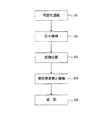
図1に示すフローチャートを参照しながら、本実施形態の発泡成形体の製造方法について説明する。 The method for producing the foamed molded article of the present embodiment will be described with reference to the flowchart shown in FIG.
[発泡成形体の製造装置]
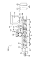
まず、本実施形態で用いる発泡成形体を製造する製造装置について説明する。本実施形態では、図2に示す製造装置(射出成形装置)1000を用いて発泡成形体を製造する。製造装置1000は、主に、スクリュ20が内設された可塑化シリンダ210と、物理発泡剤を可塑化シリンダ210に供給する物理発泡剤供給機構であるボンベ100と、金型が設けられた型締めユニット(不図示)と、可塑化シリンダ210及び型締めユニットを動作制御するための制御装置(不図示)を備える。可塑化シリンダ210内において可塑化溶融された溶融樹脂は、図2における右手から左手に向かって流動する。したがって本実施形態の可塑化シリンダ210内部においては図2における右手を「上流」または「後方」、左手を「下流」または「前方」と定義する。
[Effervescent molded product manufacturing equipment]
First, a manufacturing apparatus for manufacturing the foam molded product used in the present embodiment will be described. In the present embodiment, the foam molded product is manufactured using the manufacturing apparatus (injection molding apparatus) 1000 shown in FIG. The
可塑化シリンダは、熱可塑性樹脂が可塑化溶融されて溶融樹脂となる可塑化ゾーン21と、可塑化ゾーン21の下流側に、溶融樹脂が飢餓状態となる飢餓ゾーン23とを有する。「飢餓状態」とは、溶融樹脂が飢餓ゾーン23内に充満せずに未充満となる状態である。したがって、飢餓ゾーン23内には、溶融樹脂の占有部分以外の空間が存在する。また、飢餓ゾーン23に物理発泡剤を導入するための導入口202が形成されており、導入口202には、導入速度調整容器300が接続している。ボンベ100は、導入速度調整容器300を介して可塑化シリンダ210に物理発泡剤を供給する。
The plasticizing cylinder has a
尚、製造装置1000は、飢餓ゾーン23を1つしか有していないが、本実施形態に用いられる製造装置は、これに限定されない。例えば、溶融樹脂への物理発泡剤の浸透を促進するために、飢餓ゾーン23及びそこに形成される導入口202を複数有し、複数の導入口202から物理発泡剤を可塑化シリンダ210に導入する構造であってもよい。また、製造装置1000は射出成形装置であるが、本実施形態に用いられる製造装置は、これに限定されず、例えば、押出成形装置であってもよい。
The
[発泡成形体の製造方法]
(1)熱可塑性樹脂の可塑化溶融
まず、可塑化シリンダ210の可塑化ゾーン21において、熱可塑性樹脂を可塑化溶融して溶融樹脂とする(図1のステップS1)。熱可塑性樹脂としては、目的とする成形体の種類に応じて種々の樹脂を使用できる。具体的には、例えば、ポリプロピレン、ポリメチルメタクリレート、ポリアミド、ポリカーボネート、アモルファスポリオレフィン、ポリエーテルイミド、ポリエチレンテレフタレート、ポリエーテルエーテルケトン、ABS樹脂(アクリロニトリル・ブタジエン・スチレン共重合樹脂)、ポリフェニレンスルファイド、ポリアミドイミド、ポリ乳酸、ポリカプロラクトンなどの熱可塑性樹脂、及びこれらの複合材料を用いることができる。これらの熱可塑性樹脂は、単独で用いても、二種類以上を混合して用いてもよい。また、これらの熱可塑性樹脂にガラス繊維、タルク、カーボン繊維などの各種無機フィラーを混練したものを用いることもできる。熱可塑性樹脂には、発泡核剤として機能する無機フィラーや溶融張力を高める添加剤を混合することが好ましい。これらを混合することで、発泡セルを微細化できる。本実施形態の熱可塑性は、必要に応じてその他の汎用の各種添加剤を含んでもよい。
[Manufacturing method of foam molded product]
(1) Plasticization and melting of thermoplastic resin First, in the
本実施形態では、図2に示すスクリュ20が内設された可塑化シリンダ210内で熱可塑性樹脂の可塑化溶融を行う。可塑化シリンダ210の外壁面にはバンドヒータ(図示せず)が配設されており、これにより可塑化シリンダ210が加熱され、更にスクリュ20の回転による剪断発熱も加わり、熱可塑性樹脂が可塑化溶融される。
In the present embodiment, the thermoplastic resin is plasticized and melted in the
(2)飢餓ゾーンの圧力保持
次に、一定圧力の物理発泡剤を導入速度調整容器に供給し、導入速度調整容器300から飢餓ゾーン23に一定圧力の加圧流体を導入して、飢餓ゾーン23を前記一定圧力に保持する(図1のステップS2)。
(2) Holding the pressure in the hunger zone Next, a constant pressure physical foaming agent is supplied to the introduction rate adjusting container, and a constant pressure pressurized fluid is introduced from the introduction
物理発泡剤としては、加圧流体を用いる。本実施形態において「流体」とは、液体、気体、超臨界流体のいずれかを意味する。また、物理発泡剤は、コストや環境負荷の観点から、二酸化炭素、窒素等が好ましい。本実施形態の物理発泡剤の圧力は比較的低圧であるため、例えば、窒素ボンベ、二酸化炭素ボンベ、空気ボンベ等の流体が貯蔵されたボンベから、減圧弁により一定圧力に減圧して取り出した流体を用いることができる。この場合、昇圧装置が不要となるので、製造装置全体のコストを低減できる。また、必要であれば所定の圧力まで昇圧した流体を物理発泡剤として用いてもよい。例えば、物理発泡剤として窒素を使用する場合、以下の方法で物理発泡剤を生成できる。まず、大気中の空気をコンプレッサーで圧縮しながら窒素分離膜を通して窒素を精製する。次に、精製した窒素をブースターポンプやシリンジポンプ等を用いて所定圧力まで昇圧し、物理発泡剤を生成する。また、圧縮空気を物理発泡剤として利用してもよい。本実施形態では、物理発泡剤と溶融樹脂の強制的な剪断混錬を行わない。このため、物理発泡剤として圧縮空気を用いても、溶融樹脂に対して溶解性の低い酸素は溶融樹脂に溶解し難く、溶融樹脂の酸化劣化を抑制できる。 A pressurized fluid is used as the physical foaming agent. In the present embodiment, the "fluid" means any of a liquid, a gas, and a supercritical fluid. Further, the physical foaming agent is preferably carbon dioxide, nitrogen or the like from the viewpoint of cost and environmental load. Since the pressure of the physical foaming agent of the present embodiment is relatively low, for example, a fluid taken out from a cylinder in which a fluid such as a nitrogen cylinder, a carbon dioxide cylinder, or an air cylinder is stored is reduced to a constant pressure by a pressure reducing valve. Can be used. In this case, since the booster is not required, the cost of the entire manufacturing apparatus can be reduced. Further, if necessary, a fluid pressurized to a predetermined pressure may be used as the physical foaming agent. For example, when nitrogen is used as the physical foaming agent, the physical foaming agent can be produced by the following method. First, nitrogen is purified through a nitrogen separation membrane while compressing the air in the atmosphere with a compressor. Next, the purified nitrogen is boosted to a predetermined pressure using a booster pump, a syringe pump, or the like to generate a physical foaming agent. Further, compressed air may be used as a physical foaming agent. In this embodiment, the physical foaming agent and the molten resin are not forcibly sheared and kneaded. Therefore, even if compressed air is used as the physical foaming agent, oxygen having low solubility in the molten resin is difficult to dissolve in the molten resin, and oxidative deterioration of the molten resin can be suppressed.
飢餓ゾーン23に導入する物理発泡剤の圧力は一定であり、導入される物理発泡剤と同一の一定圧力に飢餓ゾーン23の圧力は保持される。この物発泡剤の圧力は、1MPa〜20MPaが好ましく、1MPa〜15MPaがより好ましく、2MPa〜8MPaが更により好ましい。溶融樹脂の種類により最適な圧力は異なるが、物理発泡剤の圧力を1MPa以上とすることで、発泡させるのに必要な量の物理発泡剤を溶融樹脂内に浸透させることができ、20MPa以下とすることで、装置負荷を低減できる。尚、溶融樹脂を加圧する物理発泡剤の圧力が「一定である」とは、所定圧力に対する圧力の変動幅が、好ましくは±20%以内、より好ましくは±10%以内であることを意味する。飢餓ゾーンの圧力は、例えば、可塑化シリンダ210の飢餓ゾーン23内に設けられた圧力センサ27により測定される。尚、スクリュ20の進退に伴い、飢餓ゾーン23は可塑化シリンダ210内を前後方向に移動するが、図2に示す圧力センサ27は、飢餓ゾーン23の最前進位置及び最後退位置において、常に飢餓ゾーン23内に存在する位置に設けられる。また、導入口202に対向する位置も、常に飢餓ゾーン23内にある。したがって、圧力センサ27は導入口202に対向する位置には設けられていないが、圧力センサ27の示す圧力と、導入口202に対向する位置の圧力は、ほぼ同一である。また、本実施形態では、飢餓ゾーン23に物理発泡剤のみを導入するが、本発明の効果に影響を与えない程度に、物理発泡剤以外の他の加圧流体を同時に飢餓ゾーン23に導入してもよい。この場合、飢餓ゾーン23に導入される物理発泡剤を含む加圧流体は、上述の一定圧力を有する。
The pressure of the physical foaming agent introduced into the
本実施形態では、図2に示すように、ボンベ100から導入速度調整容器300を介し、導入口202から飢餓ゾーン23へ物理発泡剤を供給する。物理発泡剤は、減圧弁151を用いて所定の圧力に減圧した後、昇圧装置等を経ることなく、導入口202から飢餓ゾーン23で導入される。本実施形態では、可塑化シリンダ210に導入する物理発泡剤の導入量、導入時間等を制御しない。そのため、それらを制御する機構、例えば、逆止弁や電磁弁等を用いた駆動弁は不要であり、導入口202は、駆動弁を有さず、常に開放されている。本実施形態では、ボンベ100から供給される物理発泡剤により、減圧弁151から、導入速度調整容器300を経て、可塑化シリンダ210内の飢餓ゾーン23まで、一定の物理発泡剤の圧力に保持される。
In the present embodiment, as shown in FIG. 2, the physical foaming agent is supplied from the
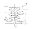
物理発泡剤の導入口202は、従来の製造装置の物理発泡剤の導入口と比較して内径D1が大きい。このため、比較的低圧の物理発泡剤であっても、可塑化シリンダ210内に効率良く導入できる。また、溶融樹脂の一部が導入口202に接触して固化した場合であっても、内径D1が大きいため、完全に塞がることなく導入口として機能できる。例えば、可塑化シリンダ210の内径が大きい場合、即ち、可塑化シリンダの外径が大きい場合に、導入口202の内径D1を大きくし易い。一方、導入口202の内径D1が大き過ぎると、溶融樹脂の滞留が発生して成形不良の原因となり、また、導入口202に接続する導入速度調整容器300が大型化して装置全体のコストが上昇する。具体的には、導入口202の内径D1は、可塑化シリンダ210の内径の20%〜100%が好ましく、30%〜80%がより好ましい。または、可塑化シリンダ210の内径に依存せず、導入口202の内径D1は、3mm〜150mmが好ましく、5mm〜100mmがより好ましい。ここで、導入口202の内径D1とは、図3に示す、可塑化シリンダ210の内壁210a上における開口部の内径を意味する。また、導入口202の形状、即ち、可塑化シリンダ210の内壁210a上における開口部の形状は、真円に限られず、楕円や多角形であってもよい。導入口202の形状が楕円や多角形である場合には、導入口202の面積と同じ面積の真円におけるその直径を「導入口202の内径D1」と定義する。
The
<導入速度調整容器>
導入口202に接続する導入速度調整容器300について説明する。導入口202に接続する導入速度調整容器300は、一定以上の容積を有することで、可塑化シリンダ210へ導入される物理発泡剤の流速を緩やかにし、導入速度調整容器300内に物理発泡剤が滞留できる時間を確保できる。導入速度調整容器300は、周囲に配置されたバンドヒーター(図示せず)により加熱された可塑化シリンダ210に直接接続されることにより、可塑化シリンダ210の熱が導入速度調整容器300に伝導される。これにより、導入速度調整容器300内部の物理発泡剤は加温され、物理発泡剤と溶融樹脂との温度差が小さくなり、物理発泡剤が接触する溶融樹脂の温度を極度に低下させることを抑制し、物理発泡剤の溶融樹脂への溶解量(浸透量)を安定化できる。即ち、導入速度調整容器300は、物理発泡剤の加温機能を有するバッファー容器として機能する。一方で、導入速度調整容器300は、その容積が大きすぎると、装置全体のコストが上昇する。導入速度調整容器300の容積は、飢餓ゾーン23に存在する溶融樹脂の量にも依存するが、5mL〜20Lが好ましく、10mL〜2Lがより好ましく、10mL〜1Lが更により好ましい。導入速度調整容器300の容積をこの範囲とすることで、コストを考慮しながら物理発泡剤が滞留できる時間を確保できる。
<Introduction speed adjustment container>
The introduction
また、後述するように物理発泡剤は溶融樹脂に接触して浸透することにより、可塑化シリンダ210内で消費される。飢餓ゾーン23の圧力を一定に保持するために、消費された分の物理発泡剤が導入速度調整容器300から飢餓ゾーン23へ導入される。導入速度調整容器300の容積が小さすぎると、物理発泡剤の置換頻度が高くなるため、物理発泡剤の温度が不安定となり、その結果、物理発泡剤の供給が不安定になる虞がある。したがって、導入速度調整容器300は、1〜10分間に可塑化シリンダにおいて消費される量の物理発泡剤が滞留できる容積を有することが好ましい。また、例えば、導入速度調整容器300の容積は、当該導入速度調整容器300が接続される飢餓ゾーン23の容積の0.1倍〜5倍が好ましく、0.5倍〜2倍がより好ましい。本実施形態では、飢餓ゾーン23の容積は、溶融樹脂を含まない、空の可塑化シリンダ210において、スクリュ20の軸の直径及びスクリュフライトの深さが一定である部分が位置する領域(23)の容積を意味する。
Further, as will be described later, the physical foaming agent is consumed in the
本実施形態で用いる導入速度調整容器300は、図3に示すように、筒状の容器本体310と、容器本体310を可塑化シリンダ210に連結する連結部材320と、容器本体310の蓋330から主に構成される。筒状の容器本体310の一方の端部は、連結部材320を介して導入口202に接続し、導入口202を介して、可塑化シリンダ210の飢餓ゾーン23と、内部空間311が連通する。また、筒状の容器本体の他方の端部(導入口202と反対側の端部)には、蓋330が開閉可能に設けられる。そして、容器本体310には、内部空間311に物理発泡剤を供給するための配管154が接続する。
As shown in FIG. 3, the introduction
また、導入速度調整容器300の内部空間311の形状に着目した場合、導入速度調整容器300は、導入口202に接続し、その内径が変化しない筒状の第1ストレート部31と、第1ストレート部31に隣接して設けられ、導入口202から離れるに従って、その内径が大きくなるテーパー部32と、テーパー部32に隣接して設けられ、その内径が変化しない筒状の第2ストレート部33とを有する。即ち、導入速度調整容器300は、図3に示すように、小さい内径D1を有する円筒である第1ストレート部31と、大きい内径D2を有する円筒である第2ストレート部33とを、それぞれの中心軸が同一の直線m上に並ぶように配置し、第1ストレート部31と第2ストレート部32とをテーパー部32のテーパー面で結合した構造を有する。本実施形態では、第1ストレート部31及び第2ストレート部33の中心軸と一致する直線mの延在方向は、筒状である速度調整容器300の延在方向と一致する。本実施形態においては、第1ストレート部31は連結部材320によって構成され、テーパー部32及び第2ストレート部33は、容器本体310によって構成される。
Further, when focusing on the shape of the
導入速度調整容器300の内径の最大値D2は、導入口の内径D1より大きい(D2>D1)。ここで、導入速度調整容器300の内径の最大値D2とは、筒状である速度調整容器300の延在方向(直線m)と直交する、内部空間311の断面において、最大の面積を有する断面(以下、「最大断面」と記載する)の内径を意味する。また、最大断面の形状は、真円に限られず、楕円や多角形であってもよい。この場合には、最大断面と同じ面積の真円におけるその直径を「導入速度調整容器300の内径の最大値D2」と定義する。本実施形態では、導入口の内径D1は、第1ストレート部31の内径、即ち連結部材320の内径に等しく、導入速度調整容器300の内径の最大値D2は、容器本体310の第2ストレート部33の内径に等しい。この特徴(D2>D1)を有する導入速度調整容器300は、例えば、以下の効果を奏する。
The maximum value D2 of the inner diameter of the introduction
例えば、導入速度調整容器300は、導入口202の内径D1を有する第1ストレート部31がテーパー部32に接続されることにより、内径がD1から次第に大きくなってD2となっているため、物理発泡剤の流通路が確保し易い。飢餓ゾーン23において溶融樹脂は飢餓状態で存在するが、それでも、溶融樹脂が導入口202から導入速度調整容器300内部へ侵入又は膨出する場合がある。この場合、溶融樹脂は導入速度調整容器300により熱を奪われ、粘度が上昇して流動性が低下し、更に温度が低下すると固化する。固化により、溶融樹脂の導入速度調整容器300内部へ侵入を阻止できるが、固化した溶融樹脂によって、物理発泡剤の流通路が完全に塞がれると、物理発泡剤を飢餓ゾーン23に供給できないという問題が生じる。そこで、本実施形態の導入速度調整容器300は、導入口202の内径D1を有する第1ストレート部31がテーパー部32に接続されることにより、導入口202から離れるにつれて内径がD1から次第に大きくなってD2となっている。導入口202から離れるほど、侵入した溶融樹脂は熱を奪われ固化し易くなるが、本実施形態の導入速度調整容器300は、導入口202から離れるにつれて容器内部が広くなっている。このため、導入口202から離れるにつれて容器壁面に接触した溶融樹脂が固化したとしても、物理発泡剤の導入路が、完全に固化した溶融樹脂によって塞がれることを抑制できる。例えば、壁面に接触した溶融樹脂が固化しても、壁面から離れた物理発泡剤の導入路の中心付近では、溶融樹脂は流動性を有する溶融状態を維持できる。これにより、導入速度調整容器300の物理発泡剤の流通路を確保できる。尚、第1ストレート部31の末端にテーパー部32が接続されていることは必ずしも必要でなく、第1ストレート部31の末端から内径が拡大するように構成されていれば、物理発泡剤の流通路は確保される。
For example, in the introduction
更に、導入速度調整容器300の内径の最大値D2を導入口202の内径D1より大きくすることにより(D2>D1)、可塑化シリンダ210からの熱伝導により導入速度調整容器300の内の物理発泡剤の加温を促進できる。上述したように、導入速度調整容器300内で物理発泡剤が加温されることで、物理発泡剤と溶融樹脂との温度差が小さくなり、物理発泡剤の溶融樹脂への溶解量(浸透量)が安定化する。本実施形態の導入速度調整容器300は、容器内部が導入口202よりも広がった形状(D2>D1)を有するため、容器内部が導入口202と同面積の形状(D2=D1)と比較して、導入速度調整容器300の下部に、即ち、可塑化シリンダ210に近い部分に、より多量の物理発泡剤を滞留させることができる。容器の下部は可塑化シリンダ210に近いため、より多量の物理発泡剤を効率的に加温できる。特に、溶融樹脂の可塑化計量開始時は、多量の物理発泡剤が導入速度調整容器300から飢餓ゾーン23に導入される。このような場合であっても、本実施形態の導入速度調整容器300は、多量の加温された物理発泡剤を飢餓ゾーン23に導入できる。尚、本実施形態では、図3に示すように、直線mを含む導入速度調整容器300の断面において、速度調整容器300の延在方向(直線m)に対するテーパー部32の内壁の角度は、45度となっているが、20度以上90度以下が、上述した効果を奏するうえで好ましい範囲として規定され、25度以上65度以下の場合が最も効果的である。尚、ここでテーパー部32の内壁の角度が90度の場合とは、第1ストレート部31と第2ストレート部33が、直線mに垂直な平面によって接続される場合をいう。
Further, by making the maximum value D2 of the inner diameter of the introduction
導入速度調整容器300の内径の最大値D2は、導入口202の内径D1より大きいため(D2>D1)、導入口の内径(D1)に対する、導入速度調整容器の内径の最大値(D2)の比率(D2/D1)は、1より大きい。上述の効果を更に促進する観点からは、上記比率(D2/D1)は、2以上が好ましい。一方、装置コスト抑制の観点からは、導入調製容器300は小さい方が好ましく、上記比率(D2/D1)は、例えば、20以下であり、10以下が好ましい。
Since the maximum value D2 of the inner diameter of the introduction
導入口202の内径D1が比較的大きい場合、例えば、導入口202の内径D1が60mm以上、好ましくは80mm以上である場合には、上述した溶融樹脂の膨出により導入口202が塞がれる虞が低下するため、上述の比率(D2/D1)は、比較的小さくてもよい。この場合、導入口の内径(D1)に対する、導入速度調整容器の内径の最大値(D2)の比率(D2/D1)は、例えば、1を超えて3以下であり、好ましくは、1を超えて2以下である。
When the inner diameter D1 of the
また、導入口202の内径D1が比較的大きい場合、導入速度調整容器300の容積も大きくなる。それに伴い、可塑化シリンダ210からの熱伝導により導入速度調整容器300内で加温される物理発泡剤の温度勾配が大きくなる虞がある。この温度勾配を小さくするために、導入速度調整容器300内に攪拌機を設け、導入速度調整容器300内の物理発泡剤を攪拌してもよい。攪拌機は、可塑化シリンダ210に近い、導入速度調整容器300内の下部、例えば、本実施形態のテーパー部31に設けることが好ましい。または、他の方法としては、多孔性又は網目状の金属板を導入速度調整容器300内の下部に設けてもよい。本実施形態においては大容積の物理発泡剤を加温するため、導入速度調整容器300の底部(第2ストレート部33の可塑化シリンダ210側の端部)に、多数の穴があいたSUS製の板(厚み5mm)311を容器本体310に連結して設置した。容器本体310からの熱伝導によって加温された金属板311により物理発泡剤の加温が促進され、導入速度調整容器300内下部における、物理発泡剤の温度勾配を小さくできる。導入速度調整容器300内下部における温度勾配を小さくすることにより、飢餓ゾーン23に導入する物理発泡剤の温度をより均一化できる。
Further, when the inner diameter D1 of the
本実施形態の導入速度調整容器300は、図3に示すように、導入口202から離れるに従って、導入速度調整容器300の内径が大きくなるテーパー部32を有することが好ましい。このようなテーパー部32を導入速度調整容器300の下部、即ち可塑化シリンダ210に近い部分に設けることにより、配管154から供給された物理発泡剤が、導入口202に近づくにつれて熱を供給するテーパー部32に近接し次第に加温される。これにより、飢餓ゾーン23に導入する物理発泡剤の温度をより均一化できる。
As shown in FIG. 3, the introduction
導入速度調整容器300において、筒状の第1ストレート部31の延在方向(直線m)(図3中の直線m)における長さ(高さ)hは、可塑化シリンダ210の側壁の厚みdの2倍以下が好ましく、1倍以下がより好ましい。第1ストレート部31の長さhが上記範囲内であれば、固化した溶融樹脂により、導入速度調整容器300内の物理発泡剤の流通路が塞がれる虞が更に低下する。筒状の第1ストレート部31の長さ(高さ)hの下限値は、特に限定されず、実質的には、例えば、可塑化シリンダ210の側壁の厚みdの0.1倍以上であり、好ましくは、0.3倍以上である。
In the introduction
蓋330は、容器本体310の第2ストレート部33に開閉可能に設けられる。蓋330は、特別な工具を用いずに、作業者の手により開閉可能であることが好ましい。発泡成形体の成形においては、事前に成形条件の設定を行う場合がある(条件出し)。成形条件の設定においては、フィーダースクリュ212やスクリュ20の回転数等の最適化を行い、飢餓ゾーン23において、飢餓状態が安定に作れているか確認する。これと同時に、導入速度調整容器300内部に導入口202から溶融樹脂が膨出しないかも確認する。このため、蓋330の開閉は、ボルトを用いず、簡便な方法で開閉可能とし、導入速度調整容器300内に侵入した樹脂を取り除けることが好ましい。蓋330を作業者の手により開閉可能とすることで、成形条件の設定の作業効率が向上する。蓋330のシール機構は任意であるが、バネを内蔵したシール機構、又はクラッチ式の高圧シール機構等を用いることができる。本実施形態では、バネを内蔵したポリイミドのシール部材331を用いる。このシール部材331は、内部空間311内に滞留する物理発泡剤のガス圧により膨張し、シール性が高まる。
The
導入速度調整容器300を構成する材料は、加圧流体を収容する観点から耐圧性であることが好ましいく、壁面での溶融樹脂の固化を促進して、容器内部への溶融樹脂の侵入を抑制する観点から、熱容量が大きく、温度が上昇しにくく、付着した樹脂から熱を奪いやすいことが好ましい。また、物理発泡剤を加温するという観点からは熱伝導率が高く、容器本体310からの熱が伝わりやすいことが好ましい。これらの観点から、導入速度調整容器300は、例えば、ステンレス鋼(SUS)等の金属で構成されることが好ましい。連結部材320も同様である。
The material constituting the introduction
導入速度調整容器300の内壁、即ち、内部空間311を区画する内壁には、テフロン(ポリテトラフルオロエチレン、PTFE)含有メッキ膜が形成されていることが好ましい。テフロン含有メッキ膜は、導入速度調整容器300の内壁全面に形成されていてもよいし、一部のみに形成されていてもよい。特に、溶融樹脂との接触の虞のある、導入速度調整容器300内の下部、例えば、第1ストレート部31及び/又はテーパー部32の内壁に形成されることが好ましい。発泡成形体の成形中に、樹脂が内壁に付着した状態で長時間経過すると、樹脂は炭化して固着し、後に剥離して、成形不良の原因となる。導入速度調整容器300の内壁にテフロン含有メッキ膜を形成することで、この溶融樹脂の固着を抑制できる。テフロン含有メッキ膜、中でも、テフロン含有無電解ニッケルリンメッキ膜は、高い耐熱性及び耐殺傷性を有し、高硬度であり、更に、複雑形状の被メッキ体への被覆性にも優れる。また、導入速度調整容器300の内壁に撥水性又は発油性を付与でき、且つ耐熱性にも優れる他の表面処理方法としては、エキシマレーザーを使った表面処理が挙げられる。しかし、導入速度調整容器300の内壁に対して、エキシマレーザーを使った表面処理を行うことは非常に困難であるため、テフロン含有メッキ膜を形成する方が好ましい。無電解メッキ膜中のテフロンの含有量は、メッキ膜の安定性と、付着する溶融樹脂の剥離性との兼ね合いから、10〜50重量%が好ましい。
It is preferable that a Teflon (polytetrafluoroethylene, PTFE) -containing plating film is formed on the inner wall of the introduction
以上、本実施形態で用いる導入速度調整容器300について説明したが、本実施形態で用いる導入速度調整容器は、この構成に限定されない。例えば、第1の変形例としては、導入速度調整容器が、テーパー部32を有さない構成が挙げられる。即ち、第1ストレート部31と、第2ストレート部33とが、テーパー面の代わりに、筒状である速度調整容器300の延在方向(直線m)と直交する面により連結されてもよい。また、第2の変形例としては、導入速度調整容器が、第1ストレート部31を有さない構成が挙げられる。この場合、可塑化シリンダ210の内壁210a上における開口部である導入口202に、テーパー部32が連結する。即ち、可塑化シリンダ210の側壁内においても、内壁210aから離れるにしたがって、導入速度調整容器300の内径が広がる構造となる。
Although the introduction
尚、導入速度調整容器300は、可塑化シリンダ210と別個体の容器であってもよいし、可塑化シリンダ210と一体に形成され、可塑化シリンダ210の一部を構成してもよい。
The introduction
(3)溶融樹脂を飢餓状態とする
次に、溶融樹脂を飢餓ゾーン23へ流動させ、飢餓ゾーン23において溶融樹脂を飢餓状態とする(図1のステップS3)。飢餓状態は、飢餓ゾーン23の上流から飢餓ゾーン23への溶融樹脂の送り量と、飢餓ゾーン23からその下流への溶融樹脂の送り量とのバランスで決定され、前者の方が少ないと飢餓状態となる。
(3) Putting the molten resin in a starvation state Next, the molten resin is made to flow to the
本実施形態では、溶融樹脂が圧縮されて圧力が高まる圧縮ゾーン22を飢餓ゾーン23の上流に設けることにより、飢餓ゾーン23において溶融樹脂を飢餓状態とする。圧縮ゾーン22には、上流側に位置する可塑化ゾーン21よりもスクリュ20の軸の直径を大きく(太く)し、スクリュフライトを段階的に浅くした大径部分20Aを設け、更に、大径部分20Aの下流側に隣接してシール部26を設ける。シール部26は、大径部分20Aと同様にスクリュ20の軸の直径が大きく(太く)、更に、スクリュフライトが設けられておらず、スクリュフライトの代わりにスクリュ20の軸に浅い溝が複数形成されている。大径部分20A及びシール部26は、スクリュ20の軸の直径を大きくすることにより、可塑化シリンダ210の内壁とスクリュ20のクリアランスを縮小し、下流に送る樹脂供給量を低減できるため、溶融樹脂の流動抵抗を高められる。したがって、本実施形態において、大径部分20A及びシール部26は、溶融樹脂の流動抵抗を高める機構である。尚、シール部26は、物理発泡剤の逆流、即ち、シール部26の下流側から上流側への物理発泡剤の移動を抑制する効果も奏する。
In the present embodiment, the molten resin is starved in the
大径部分20A及びシール部26の存在により圧縮ゾーン22から飢餓ゾーン23に供給される樹脂流量が低下し、上流側の圧縮ゾーン22においては溶融樹脂が圧縮されて圧力が高まり、下流側の飢餓ゾーン23においては、溶融樹脂が未充満(飢餓状態)となる。溶融樹脂の飢餓状態を促進するために、スクリュ20は、圧縮ゾーン22に位置する部分と比較して、飢餓ゾーン23に位置する部分の軸の直径が小さく(細く)、且つスクリュフライトが深い構造を有する。更に、スクリュ20は、圧縮ゾーン22に位置する部分と比較して、飢餓ゾーン23全体に亘って、そこに位置する部分の軸の直径が小さく(細く)、且つスクリュフライトが深い構造を有することが好ましい。更に、飢餓ゾーン23全体に亘って、スクリュ20の軸の直径及びスクリュフライトの深さは、略一定であることが好ましい。これにより、飢餓ゾーン23における圧力を略一定に保持し、溶融樹脂の飢餓状態を安定化できる。本実施形態においては、飢餓ゾーン23は、図2に示すように、スクリュ20において、スクリュ20の軸の直径及びスクリュフライトの深さが一定である部分に形成される。
Due to the presence of the
圧縮ゾーン22に設けられる溶融樹脂の流動抵抗を高める機構は、圧縮ゾーン22から飢餓ゾーン23へ供給される樹脂流量を制限するために一時的に溶融樹脂が通過する流路面積を縮小させる機構であれば、特に制限されない。本実施形態では、スクリュの大径部分20A及びシール部26の両方を用いたが、片方のみ用いてもよい。スクリュの大径部分20A、シール部26以外の流動抵抗を高める機構としては、スクリュフライトが他の部分とは逆向きに設けられた構造、スクリュ上に設けられたラビリンス構造等が挙げられる。
The mechanism for increasing the flow resistance of the molten resin provided in the
溶融樹脂の流動抵抗を高める機構は、スクリュとは別部材のリング等としてスクリュに設けてもよいし、スクリュの構造の一部としてスクリュと一体に設けてもよい。溶融樹脂の流動抵抗を高める機構は、スクリュとは別部材のリング等として設けると、リングを変更することにより溶融樹脂の流路であるクリアランス部の大きさを変更できるので、容易に溶融樹脂の流動抵抗の大きさを変更できるという利点がある。 A mechanism for increasing the flow resistance of the molten resin may be provided on the screw as a ring or the like of a member separate from the screw, or may be provided integrally with the screw as a part of the structure of the screw. If a mechanism for increasing the flow resistance of the molten resin is provided as a ring or the like of a member separate from the screw, the size of the clearance portion which is the flow path of the molten resin can be changed by changing the ring, so that the molten resin can be easily provided. There is an advantage that the magnitude of the flow resistance can be changed.
また、融樹脂の流動抵抗を高める機構以外に、飢餓ゾーン23から上流の圧縮ゾーン22へ溶融樹脂の逆流を防止する逆流防止機構(シール機構)を圧縮ゾーン22の飢餓ゾーン23との間に設けることによっても、飢餓ゾーン23において溶融樹脂を飢餓状態にできる。例えば、物理発泡剤の圧力により上流側に移動可能なリング、鋼球等のシール機構が挙げられる。但し、逆流防止機構は駆動部を必要とするため、樹脂滞留の虞がある。このため、駆動部を有さない流動抵抗を高める機構の方が好ましい。
Further, in addition to the mechanism for increasing the flow resistance of the molten resin, a backflow prevention mechanism (seal mechanism) for preventing the backflow of the molten resin from the
本実施形態では、飢餓ゾーン23における溶融樹脂の飢餓状態を安定化させるために、可塑化シリンダ210へ供給する熱可塑性樹脂の供給量を制御してもよい。熱可塑性樹脂の供給量が多すぎると飢餓状態を維持することが困難となるからである。本実施形態では、汎用のフィーダースクリュ212を用いて、熱可塑性樹脂の供給量を制御する。熱可塑性樹脂の供給量が制限されることにより、飢餓ゾーン23における溶融樹脂の計量速度が、圧縮ゾーン22での可塑化速度よりも大きくなる。この結果、飢餓ゾーン23における溶融樹脂の密度が安定に低下し、溶融樹脂への物理発泡剤の浸透が促進される。
In the present embodiment, the amount of the thermoplastic resin supplied to the
本実施形態において、溶融樹脂の流動方向における飢餓ゾーン23の長さは、溶融樹脂と物理発泡剤との接触面積や接触時間を確保するために長いほうが好ましいが、長すぎると成形サイクルやスクリュ長さが長くなる弊害生じる。このため、飢餓ゾーン23の長さは、可塑化シリンダ210の内径の2倍〜12倍が好ましく、4倍〜10倍がより好ましい。また、飢餓ゾーン23の長さは、射出成形における計量ストーロークの全範囲を賄うことが好ましい。即ち、溶融樹脂の流動方向における飢餓ゾーン23の長さは、射出成形における計量ストーロークの長さ以上であることが好ましい。溶融樹脂の可塑化計量及び射出に伴ってスクリュ20は前方及び後方に移動するが、飢餓ゾーン23の長さを計量ストーロークの長さ以上とすることで、発泡成形体の製造中、常に、導入口202を飢餓ゾーン23内に配置する(形成する)ことができる。換言すれば、発泡成形体の製造中にスクリュ20が前方及び後方に動いても、飢餓ゾーン23以外のゾーンが、導入口202の位置に来ることはない。これにより、導入口202から導入される物理発泡剤は、発泡成形体の製造中、常に、飢餓ゾーン23に導入される。このように十分且つ適当な大きさ(長さ)を有する飢餓ゾーンを設け、そこに一定圧力の物理発泡剤を導入することで、飢餓ゾーン23を一定圧力により保持し易くなる。本実施形態においては、飢餓ゾーン23の長さは、図2に示すように、スクリュ20において、スクリュ20の軸の直径及びスクリュフライトの深さが一定である部分の長さと略同一である。
In the present embodiment, the length of the
更に、圧縮ゾーン22と飢餓ゾーン23の間に、流動速度調整ゾーン25を設けてもよい。流動速度調整ゾーン25の上流の圧縮ゾーン22における溶融樹脂の流動速度と、下流の飢餓ゾーン23における溶融樹脂の流動速度とを比較すると、飢餓ゾーン23における溶融樹脂の流動速度の方が早い。本発明者らは、圧縮ゾーン22と飢餓ゾーン23の間に、緩衝ゾーンとなる流動速度調整ゾーン25を設け、この急激な溶融樹脂の流動速度の変化(上昇)を抑制することにより、製造される発泡成形体の発泡性が向上することを見出した。圧縮ゾーン22から飢餓ゾーン23の間に緩衝ゾーンとなる流動速度調整ゾーン25を設けることで、発泡成形体の発泡性が向上する理由の詳細は不明であるが、流動速度調整ゾーン25に溶融樹脂が滞留することにより飢餓ゾーン23から流入した物理発泡剤と溶融樹脂が混練され、接触時間が長くなることが一因ではないかと推測される。本実施形態では、図2に示す可塑化スクリュ20の流動速度調整ゾーン25に位置する部分に、減圧部及び圧縮部を設けることによって、即ち、スクリュフライトの深さを変化させることによって、更に換言すれば、スクリュ径の大きさ(太さ)を変化させることによって溶融樹脂の流動速度を調整する。
Further, a flow
(4)溶融樹脂と物理発泡剤の接触
次に、飢餓ゾーン23を一定圧力に保持した状態で、飢餓ゾーン23において飢餓状態の溶融樹脂と一定圧力の前記物理発泡剤とを接触させる(図1のステップS4)。即ち、飢餓ゾーン23において、溶融樹脂を物理発泡剤により一定圧力で加圧する。飢餓ゾーン23は溶融樹脂が未充満(飢餓状態)であり物理発泡剤が存在できる空間があるため、物理発泡剤と溶融樹脂とを効率的に接触させることができる。溶融樹脂に接触した物理発泡剤は、溶融樹脂に浸透して消費される。物理発泡剤が消費されると、導入速度調整容器300中に滞留している物理発泡剤が飢餓ゾーン23に供給される。これにより、飢餓ゾーン23の圧力は一定圧力に保持され、溶融樹脂は一定圧力の物理発泡剤に接触し続ける。
(4) Contact between the molten resin and the physical foaming agent Next, while the
従来の物理発泡剤を用いた発泡成形では、可塑化シリンダに所定量の高圧の物理発泡剤を所定時間内に強制的に導入していた。したがって、物理発泡剤を高圧力に昇圧し、溶融樹脂への導入量、導入時間等を正確に制御する必要があり、物理発泡剤が溶融樹脂に接触するのは、短い導入時間のみであった。これに対して本実施形態では、可塑化シリンダ210に物理発泡剤を強制的に導入するのではなく、飢餓ゾーン23の圧力が一定となるように、一定圧力の物理発泡剤を連続的に可塑化シリンダ内に供給し、連続的に物理発泡剤を溶融樹脂に接触させる。これにより、温度及び圧力により決定される溶融樹脂への物理発泡剤の溶解量(浸透量)が、安定化する。また、本実施形態の物理発泡剤は、常に溶融樹脂に接触しているため、必要十分な量の物理発泡剤が溶融樹脂内に浸透できる。これにより、本実施形態で製造する発泡成形体は、従来の物理発泡剤を用いた成形方法と比較して低圧の物理発泡剤を用いているのにもかかわらず、発泡セルが微細である。
In the conventional foam molding using a physical foaming agent, a predetermined amount of a high-pressure physical foaming agent is forcibly introduced into the plasticizing cylinder within a predetermined time. Therefore, it is necessary to boost the pressure of the physical foaming agent to a high pressure and accurately control the introduction amount, introduction time, etc. into the molten resin, and the physical foaming agent comes into contact with the molten resin only in a short introduction time. .. On the other hand, in the present embodiment, instead of forcibly introducing the physical foaming agent into the
また、本実施形態の製造方法は、物理発泡剤の導入量、導入時間等を制御する必要が無いため、逆止弁や電磁弁等の駆動弁、更にこれらを制御する制御機構が不要となり、装置コストを抑えられる。また、本実施形態で用いる物理発泡剤は従来の物理発泡剤よりも低圧であるため装置負荷も小さい。 Further, since the manufacturing method of the present embodiment does not need to control the introduction amount, introduction time, etc. of the physical foaming agent, a drive valve such as a check valve or a solenoid valve, and a control mechanism for controlling these are not required. Equipment cost can be suppressed. Further, since the physical foaming agent used in the present embodiment has a lower pressure than the conventional physical foaming agent, the device load is small.
本実施形態では、発泡成形体の製造中、常に、飢餓ゾーン23を一定圧力に保持する。つまり、可塑化シリンダ内で消費された物理発泡剤を補うために、前記一定圧力の物理発泡剤を連続的に供給しながら、発泡成形体の製造方法の全ての工程が実施される。また、本実施形態では、例えば、連続で複数ショットの射出成形を行う場合、射出工程、成形体の冷却工程及び成形体の取出工程が行われている間も、次のショット分の溶融樹脂が可塑化シリンダ内で準備されており、次のショット分の溶融樹脂が物理発泡剤により一定圧力で加圧される。つまり、連続で行う複数ショットの射出成形では、可塑化シリンダ内に、溶融樹脂と一定圧力の物理発泡剤が常に存在して接触している状態、つまり、可塑化シリンダ内で溶融樹脂が物理発泡剤により一定圧力で常時、加圧された状態で、可塑化計量工程、射出工程、成形体の冷却工程、取り出し工程等を含む、射出成形の1サイクルが行われる。同様に、押出成形等の連続成形を行う場合にも、可塑化シリンダ内に、溶融樹脂と一定圧力の物理発泡剤が常に存在して接触している状態、つまり、可塑化シリンダ内で溶融樹脂が物理発泡剤により一定圧力で常時、加圧された状態で成形が行われる。
In the present embodiment, the
(5)発泡成形
次に、物理発泡剤を接触させた溶融樹脂を発泡成形体に成形する(図1のステップS5)。本実施形態で用いる可塑化シリンダ210は、飢餓ゾーン23の下流に、飢餓ゾーン23に隣接して配置され、溶融樹脂が圧縮されて圧力が高まる再圧縮ゾーン24を有する。まず、可塑化スクリュ20の回転により、飢餓ゾーン23の溶融樹脂を再圧縮ゾーン24に流動させる。物理発泡剤を含む溶融樹脂は、再圧縮ゾーン24において圧力調整され、可塑化スクリュ20の前方に押し出されて計量される。このとき、可塑化スクリュ20の前方に押し出された溶融樹脂の内圧は、可塑化スクリュ20の後方に接続する油圧モータ又は電動モータ(不図示)により、スクリュ背圧として制御される。本実施形態では、溶融樹脂から物理発泡剤を分離させずに均一相溶させ、樹脂密度を安定化させるため、可塑化スクリュ20の前方に押し出された溶融樹脂の内圧、即ち、スクリュ背圧は、一定に保持されている飢餓ゾーン23の圧力よりも1〜6MPa程度高く制御することが好ましい。尚、本実施形態では、スクリュ20前方の圧縮された樹脂が上流側に逆流しないように、スクリュ20の先端にチェックリング50が設けられる。これにより、計量時、飢餓ゾーン23の圧力は、スクリュ20前方の樹脂圧力に影響されない。
(5) Foam molding Next, the molten resin in contact with the physical foaming agent is molded into a foam molded body (step S5 in FIG. 1). The
発泡成形体の成形方法は、特に限定されず、例えば、射出発泡成形、押出発泡成形、発泡ブロー成形等により成形体を成形できる。本実施形態では、図2に示す可塑化シリンダ210から、金型内のキャビティ(不図示)に、計量した溶融樹脂を射出充填して射出発泡成形を行う。射出発泡成形としては、金型キャビティ253内に、金型キャビティ容積の75%〜95%の充填容量の溶融樹脂を充填して、気泡が拡大しながら金型キャビティを充填するショートショット法を用いてもよいし、また、金型キャビティ容積100%の充填量の溶融樹脂を充填した後、キャビティ容積を拡大させて発泡させるコアバック法を用いてもよい。得られる発泡成形体は内部に発泡セルを有するため、熱可塑性樹脂の冷却時の収縮が抑制されてヒケやソリが軽減され、低比重の成形体を得られる。
The molding method of the foam molded product is not particularly limited, and the molded product can be molded by, for example, injection foam molding, extrusion foam molding, foam blow molding, or the like. In the present embodiment, the
以上説明した本実施形態の製造方法では、物理発泡剤の溶融樹脂への導入量、導入時間等を制御する必要がため、複雑な制御装置を省略又は簡略化でき、装置コストを削減できる。また、本実施形態の発泡成形体の製造方法は、飢餓ゾーン23を一定圧力に保持した状態で、飢餓ゾーン23において、飢餓状態の溶融樹脂と前記一定圧力の物理発泡剤とを接触させる。これにより、物理発泡剤の溶融樹脂に対する溶解量(浸透量)を単純な機構により安定化できる。
In the manufacturing method of the present embodiment described above, since it is necessary to control the amount of the physical foaming agent introduced into the molten resin, the introduction time, and the like, a complicated control device can be omitted or simplified, and the device cost can be reduced. Further, in the method for producing a foamed molded product of the present embodiment, the molten resin in the starvation state is brought into contact with the physical foaming agent at the constant pressure in the
以下、本発明について実施例及び比較例を用いて更に説明する。但し、本発明は、以下に説明する実施例及び比較例に限定されるものではない。 Hereinafter, the present invention will be further described with reference to Examples and Comparative Examples. However, the present invention is not limited to the examples and comparative examples described below.
[実施例1]
本実施例では、熱可塑性樹脂としてミネラル強化ポリアミド6(PA6)を用い、物理発泡剤として窒素を利用して発泡成形体を製造した。
[Example 1]
In this example, a foam molded product was produced using mineral-reinforced polyamide 6 (PA6) as the thermoplastic resin and nitrogen as the physical foaming agent.
(1)製造装置
本実施例では、上述した実施形態で用いた図2に示す製造装置1000を用いた。製造装置1000の詳細について説明する。上述のように、製造装置1000は射出成形装置であり、可塑化シリンダ210と、物理発泡剤を可塑化シリンダ210に供給する物理発泡剤供給機構であるボンベ100と、金型が設けられた型締めユニット(不図示)と、可塑化シリンダ210及び型締めユニットを動作制御するための制御装置(不図示)を備える。
(1) Manufacturing device In this embodiment, the
可塑化シリンダ210のノズル先端29には、エアシリンダの駆動により開閉するシャットオフバルブ28が設けられ、可塑化シリンダ210の内部を高圧に保持できる。ノズル先端29には金型(不図示)が密着し、金型が形成するキャビティ内にノズル先端29から溶融樹脂が射出充填される。可塑化シリンダ210の上部側面には、上流側から順に、熱可塑性樹脂を可塑化シリンダ210に供給するための樹脂供給口201及び物理発泡剤を可塑化シリンダ210内に導入するための導入口202が形成される。これらの樹脂供給口201及び導入口202にはそれぞれ、樹脂供給用ホッパ211及びフィーダースクリュ212、導入速度調整容器300が配設される。導入速度調整容器300には、ボンベ100が、減圧弁151、圧力計152、開放弁153を介して、配管154により接続する。導入速度調整容器300の容器本体310及び連結部材320の内壁には、テフロン含有無電解ニッケルリンメッキ膜を形成した。メッキ膜の膜厚は20μm、メッキ膜中のテフロンの含有量は、約30重量%とした。また、可塑化シリンダ210の飢餓ゾーン23内には、飢餓ゾーン23の圧力をモニターするセンサ27が設けられている。
A shut-off
スクリュ20は、熱可塑性樹脂の可塑化溶融を促進し、溶融樹脂の計量及び射出を行うため、可塑化シリンダ210内において回転及び進退自在に配設されている。スクリュ20には、上述したように、溶融樹脂の流動抵抗を高める機構として、シール部26及びスクリュ20の大径部分20Aが設けられている。
The
可塑化シリンダ210では、樹脂供給口201から可塑化シリンダ210内に熱可塑性樹脂が供給され、熱可塑性樹脂がバンドヒータ(不図示)によって可塑化されて溶融樹脂となり、スクリュ20が正回転することにより下流に送られる。スクリュ20に設けられたシール部26及び大径部分20Aの存在により、シール部26の上流側では、溶融樹脂が圧縮されて圧力が高まり、シール部26の下流の飢餓ゾーン23では、溶融樹脂が未充満(飢餓状態)となる。更に下流に送られた溶融樹脂は、射出前に可塑化シリンダ210の先端付近において再圧縮されて計量される。
In the
これにより、可塑化シリンダ210内では、上流側から順に、熱可塑性樹脂が可塑化溶融される可塑化ゾーン21、溶融樹脂が圧縮されて圧力が高まる圧縮ゾーン22、溶融樹脂の流動速度を調整する流動速度調整ゾーン25、溶融樹脂が未充満となる飢餓ゾーン23、飢餓ゾーンにおいて減圧された溶融樹脂が再度圧縮される再圧縮ゾーン24が形成される。
As a result, in the
製造装置1000において、可塑化シリンダ210の内径は35mmであり、導入口202の内径D1は8mmであった。したがって、導入口202の内径D1は、可塑化シリンダ210の内径の約23%であった。導入速度調整容器300の内径の最大値D2は80mmであった。したがって、導入速度調整容器300の内径の最大値D2は、導入口の内径D1より大きく(D2>D1)、比率(D2/D1)は、10であった。また、導入速度調整容器300の第1ストレート部31の長さhは、12mmであり、可塑化シリンダ210の側壁の厚みdは、40mmであった。したがって、第1ストレート部31の長さhは、可塑化シリンダ210の側壁の厚みdの0.3倍であった。また、導入速度調整容器300の容積は約80mLであり、飢餓ゾーン23の容積は、110mLであった。したがって、導入速度調整容器300の容積は、飢餓ゾーン23の容積の約0.7倍であった。また、本実施例では、キャビティの大きさが100mm×200mm×3mmである金型を用いた。
In the
(2)発泡成形体の製造
本実施例では、ボンベ100として、窒素が14.5MPaで充填された容積47Lの窒素ボンベを用いた。まず、減圧弁151の値を4MPaに設定し、ボンベ100を開放し、減圧弁151、圧力計152、更に導入速度調整容器300を介して、可塑化シリンダ210の導入口202から、飢餓ゾーン23へ4MPaの窒素を供給した。成形体の製造中、ボンベ100は常時、開放した状態とした。
(2) Production of Foamed Mold In this example, a nitrogen cylinder having a volume of 47 L filled with nitrogen at 14.5 MPa was used as the
可塑化シリンダ210において、バンドヒータ(不図示)により、可塑化ゾーン21を220℃、圧縮ゾーン22を240℃、流動速度調整ゾーン25及び飢餓ゾーン23を220℃、再圧縮ゾーン24を240℃に調整した。そして、樹脂供給用ホッパ211から、フィーダースクリュ212を30rpmの回転数で回転させながら、熱可塑性樹脂の樹脂ペレット(東洋紡製、グラマイドT777−02)を可塑化シリンダ210に供給し、スクリュ20を正回転させた。これにより、可塑化ゾーン21において、熱可塑性樹脂を加熱、混練し、溶融樹脂とした。
In the
フィーダースクリュ212の回転数は、事前にソリッド成形体(無発泡成形体)の成形により、本実施例の成形条件の設定(条件出し)を行い、樹脂ペレットが飢餓供給される回転数に決定した。ここで、樹脂ペレットの飢餓供給とは、可塑化ゾーン21において、樹脂ペレットの供給中、可塑化シリンダ内に樹脂ペレット又はその溶融樹脂が充満しない状態が維持され、供給した樹脂ペレット又はその溶融樹脂からスクリュ20のフライトが露出している状態を意味する。樹脂ペレットの飢餓供給の確認は、例えば、赤外線センサ又は可視化カメラにてスクリュ20上の樹脂ペレット又は溶融樹脂の有無を確認する方法が挙げられる。本実施例では、用いたフィーダースクリュ212に透明窓が設けられており、透明窓を介して樹脂供給口201直下の可塑化ゾーン21の状態を視認して確認した。
The rotation speed of the
スクリュ20を背圧6MPa、回転数100rpmにて正回転することにより、溶融樹脂を可塑化ゾーン21から圧縮ゾーン22に流動させ、更に、流動速度調整ゾーン25及び飢餓ゾーン23に流動させた。
By rotating the
溶融樹脂は、スクリュ大径部分20A及びシール部26と、可塑化シリンダ210の内壁との隙間から、流動速度調整ゾーン25及び飢餓ゾーン23へ流動するため、飢餓ゾーン23への溶融樹脂の供給量が制限された。これにより、圧縮ゾーン22においては溶融樹脂が圧縮されて圧力が高まり、下流側の飢餓ゾーン23においては、溶融樹脂が未充満(飢餓状態)となった。飢餓ゾーン23では、溶融樹脂が未充満(飢餓状態)であるため、溶融樹脂が存在しない空間に導入口202から導入された物理発泡剤(窒素)が存在し、その物理発泡剤により溶融樹脂は加圧された。
Since the molten resin flows to the drift
更に、溶融樹脂は再圧縮ゾーン24に送られて再圧縮され、可塑化シリンダ210の先端部において1ショット分の溶融樹脂が計量された。その後、シャットオブバルブ28を開放して、キャビティ内に、キャビティの容積の90%の充填率となる様に溶融樹脂を射出充填して平板形状の発泡成形体を成形した(ショートショット法)。成形後、発泡成形体が冷却するのを待って、金型内から発泡成形体を取り出した。冷却時間は、10秒とした。成形サイクルは18秒であり、ソリッド成形体(無発泡の成形体)の成形サイクルと同等の値であった。
Further, the molten resin was sent to the
以上説明した成形体の射出成形を連続して1000ショット行い、1000個の発泡成形体を得た。1000個の発泡成形体の製造中、常時、圧力センサ27により可塑化シリンダ210内の飢餓ゾーン23の圧力を計測した。その結果、飢餓ゾーン23の圧力は、常に4MPaで一定であった。また、飢餓ゾーン23へ供給される窒素の圧力を示す圧力計152の値も、発泡成形体の製造中、常時、4MPaであった。以上から、可塑化計量工程、射出工程、成形体の冷却工程、取り出し工程等を含む射出成形の1サイクルを通して、飢餓ゾーン23において、4MPaの窒素により溶融樹脂が、常時、加圧されていたこと、及び1000個の成形体の連続成形の間、飢餓ゾーン23において、窒素により溶融樹脂が、常時、加圧されていたことが確認できた。
Injection molding of the molded product described above was continuously performed for 1000 shots to obtain 1000 foam molded products. During the production of 1000 foam moldings, the pressure in the
1000個の発泡成形体の重量ばらつきを標準偏差(σ)を重量平均値(ave.)で割った値(相対標準偏差値:σ/ave.(%))で評価した。その結果、(σ/ave.)=0.21%であった。同様の評価をソリッド成形体(無発泡の成形体)で行ったところ、(σ/ave.)=0.18%で、本実施例と同等の値であった。この結果から、本実施例の発泡成形体の重量安定性は、ソリッド成形体と同等であることがわかった。 The weight variation of 1000 foam moldings was evaluated by dividing the standard deviation (σ) by the weight average value (ave.) (Relative standard deviation value: σ / ave. (%)). As a result, (σ / ave.) = 0.21%. When the same evaluation was performed on a solid molded product (non-foamed molded product), (σ / ave.) = 0.18%, which was the same value as in this example. From this result, it was found that the weight stability of the foam molded product of this example was equivalent to that of the solid molded product.
本実施例では、ソリッド成形体と比較して比重が約10%程度軽く、ソリが矯正された発泡成形体を連続的に安定して製造できた。比重低減率は、物理発泡剤の溶解量(浸透量)に影響を受けると考えられる。この結果から、物理発泡剤の溶融樹脂に対する溶解量(浸透量)が安定化していたことがわかった。また、分離したガスが成形体表面にて転写して表面性を悪化させるスワールマークは、僅かな発生にとどまっていた。更に、得られた発泡成形体断面の発泡セル状態を観察した。この結果、発泡セルの平均セル径は18μmと微細であることがわかった。 In this example, the specific gravity was about 10% lighter than that of the solid molded product, and the foam molded product with the warp corrected could be continuously and stably produced. The specific gravity reduction rate is considered to be affected by the dissolved amount (permeation amount) of the physical foaming agent. From this result, it was found that the amount of the physical foaming agent dissolved in the molten resin (permeation amount) was stabilized. Further, the swirl marks, in which the separated gas was transferred on the surface of the molded product and deteriorated the surface property, were only slightly generated. Further, the foamed cell state of the cross section of the obtained foamed molded product was observed. As a result, it was found that the average cell diameter of the foamed cell was as fine as 18 μm.
従来の超臨界流体を用いた物理発泡成形技術では、ソリッドと比較して、発泡成形体の重量ばらつきが大きくなることが周知の事実であった。しかし、本実施例ではソリッドと遜色ない、重量ばらつきの小さい発泡成形体が得られた。本実施例では、発泡成形体の重量ばらつきが、相対標準偏差値で0.5%以下と安定しており、且つ平均セル径が100μm以下の発泡成形体を得られることが確認できた。 It was a well-known fact that in the conventional physical foam molding technique using a supercritical fluid, the weight variation of the foam molded product is larger than that of the solid. However, in this example, a foam molded product having a small weight variation, which is comparable to a solid, was obtained. In this example, it was confirmed that the weight variation of the foamed molded product was stable at 0.5% or less in relative standard deviation value, and the foamed molded product having an average cell diameter of 100 μm or less could be obtained.
1000ショット連続成形後、導入速度調整容器300への窒素の導入を止め、可塑化シリンダ210内の溶融樹脂をパージにて追い出した。その後、開放弁153を開いて圧力計152の表示がゼロ(大気圧)になるまで導入速度調整容器300内の残圧を開放した。次に、蓋330のシール部材331の膨潤が元に戻るまで、約5分間待った。その後、蓋330を作業者が手で開放したところスムーズに開けることができた。導入速度調整容器300下部の第1ストレート部31付近に堆積した樹脂はわずかであり、ピンセットで完全に取り出すことができた。即ち、導入速度調整容器300の内壁に固着した樹脂は確認されなかった。
After continuous molding of 1000 shots, the introduction of nitrogen into the introduction
導入口202より取り出した樹脂は、内壁面に接する部分は固化していたが、内壁面から離れた部分は固化していなかった。これにより、第1ストレート部31に滞留樹脂は存在していたが、物理発泡剤の飢餓ゾーン23への供給は可能であったことが確認できた。
In the resin taken out from the
本実施例に用いた導入速度調整容器300に代えて、内壁にテフロン含有メッキ膜が形成されていない耐圧容器を用いた場合には、ポリアミドのような金属と相性が良い樹脂材料の成形を行うと、耐圧容器の内壁に樹脂が固着して残存し、この残存樹脂が、例えば、樹脂材料を替えて発泡成形を行う際に、コンタミとなることが分かっている。導入速度調整容器300の内壁に固着した樹脂が確認されなかったことから、本実施例において、テフロン含有メッキ膜の有効性が確認された。
When a pressure-resistant container in which a Teflon-containing plating film is not formed on the inner wall is used instead of the introduction
[実施例2]
本実施例では、物理発泡剤として二酸化炭素用いた。したがって、物理発泡剤供給装置であるボンベ100として、圧力6MPa液体二酸化炭素ボンベを用いた。そして、減圧弁151の値を5MPaに設定した。それ以外は、実施例1と同様の方法により、連続して1000個の発泡成形体を製造した。
[Example 2]
In this example, carbon dioxide was used as the physical foaming agent. Therefore, a liquid carbon dioxide cylinder having a pressure of 6 MPa was used as the
発泡成形体の製造中、常時、圧力センサ27により可塑化シリンダ210内の飢餓ゾーン23の圧力を計測した。その結果、飢餓ゾーン23の圧力は、常に5MPaで一定であった。また、飢餓ゾーン23へ供給される二酸化炭素の圧力を示す圧力計152の値も、発泡成形体の製造中、常時、5MPaであった。以上から、可塑化計量工程、射出工程、成形体の冷却工程、取り出し工程等を含む射出成形の1サイクルを通して、飢餓ゾーン23において、5MPaの二酸化炭素により溶融樹脂が、常時、加圧されていたこと、及び1000個の成形体の連続成形の間、飢餓ゾーン23において、二酸化炭素により溶融樹脂が、常時、加圧されていたことが確認できた。
During the production of the foam molded product, the pressure in the
1000個の発泡成形体の重量ばらつきを標準偏差(σ)を重量平均値(ave.)で割った値(σ/ave.(%))で評価した。その結果、(σ/ave.)=0.24%であった。同様の評価をソリッド成形体(無発泡の成形体)で行ったところ、実施例1の場合と同様に、(σ/ave.)=0.20%であり、本実施例と同等の値であった。この結果から、本実施例の発泡成形体の重量安定性は、ソリッド成形体と同等であることがわかった。 The weight variation of 1000 foam moldings was evaluated by the value (σ / ave. (%)) Of the standard deviation (σ) divided by the weight average value (ave.). As a result, (σ / ave.) = 0.24%. When the same evaluation was performed on a solid molded product (non-foaming molded product), (σ / ave.) = 0.20%, which was the same value as in this example, as in the case of Example 1. there were. From this result, it was found that the weight stability of the foam molded product of this example was equivalent to that of the solid molded product.
本実施例では、ソリッド成形体と比較して、比重が約10%程度軽く、ソリが矯正された発泡成形体を連続的に安定して製造できた。この結果から、物理発泡剤の溶融樹脂に対する溶解量(浸透量)が安定化していたことがわかった。更に、得られた発泡成形体断面の発泡セル状態を観察した。この結果、発泡セルの平均セル径は30μmと実施例1と比較して大きかったが、微細な発泡セルが得られた。本実施例と実施例1との発泡セルの大きさの相違は、物理発泡剤の種類の相違に起因すると推測される。従来の超臨界流体を用いた物理発泡成形技術では、物理発泡剤として二酸化炭素を用いると、発泡セルの微細化が困難であった。本実施例では、従来の成形技術と比較して、二酸化炭素の溶融樹脂に対する溶解量が増加するため、物理発泡剤として窒素を用いた場合(実施例1)と同程度の微細な発泡セルが形成できたを推測される。 In this example, the specific gravity was about 10% lighter than that of the solid molded product, and the foam molded product with the warp corrected could be continuously and stably produced. From this result, it was found that the amount of the physical foaming agent dissolved in the molten resin (permeation amount) was stabilized. Further, the foamed cell state of the cross section of the obtained foamed molded product was observed. As a result, the average cell diameter of the foamed cells was 30 μm, which was larger than that of Example 1, but fine foamed cells were obtained. It is presumed that the difference in the size of the foaming cell between the present embodiment and the first embodiment is due to the difference in the type of the physical foaming agent. In the conventional physical foam molding technique using a supercritical fluid, it is difficult to miniaturize the foam cell when carbon dioxide is used as the physical foaming agent. In this example, since the amount of carbon dioxide dissolved in the molten resin is increased as compared with the conventional molding technique, a fine foam cell similar to that in the case of using nitrogen as the physical foaming agent (Example 1) is produced. It is presumed that it could be formed.
本実施例の結果から、物理発泡剤として二酸化炭素を用いた場合も、飢餓ゾーン23の圧力保持を簡便な方法で行うことができ、物理発泡剤として窒素を用いた実施例1と同様の効果を得られることが分かった。
From the results of this example, even when carbon dioxide is used as the physical foaming agent, the pressure in the
[比較例1]
本比較例では、導入速度調整容器300に代えて、容器の内径(D2)が一定で、且つ、導入口202の内径D1と同一の8mmである耐圧容器を用いた(D1=D2=8mm)。耐圧容器の容積は約10mLとした。それ以外は、実施例1と同様の方法により、発泡成形体を製造した。
[Comparative Example 1]
In this comparative example, instead of the introduction
本比較例では、100ショットまでは実施例1と同様に、安定に成形できた。しかし、200ショットを超えたところで、発泡していない不良品が多発した。装置を止めて、耐圧容器の内部を確認したところ、樹脂が内部に充満していた。耐圧容器内部に樹脂が充満したため、飢餓ゾーン23へ物理発泡剤を円滑に導入できなくなり、成形不良が発生したと推測される。
In this comparative example, up to 100 shots could be stably molded as in Example 1. However, when the number of shots exceeded 200, defective products that did not foam frequently occurred. When the device was stopped and the inside of the pressure-resistant container was checked, the inside was filled with resin. Since the inside of the pressure-resistant container was filled with resin, it is presumed that the physical foaming agent could not be smoothly introduced into the
更に、本比較例で用いた装置において、成形条件を変更して、ロングランの連続成形が可能となるか検討を行った。具体的には、可塑化シリンダ210の外壁面のバンドヒータにより、飢餓ゾーン23の溶融樹脂の温度調節を行った。しかし、溶融樹脂の温度を調節しても、耐圧容器内に樹脂が充満するか、又は、導入口202付近で溶融樹脂が固化して物理発泡剤の流路を塞ぐか、どちらかの不良が発生し、ロングランの連続成形が可能な成形条件を見出すことはできなかった。この原因は、以下のように推測される。
Furthermore, in the apparatus used in this comparative example, it was examined whether continuous molding of long run is possible by changing the molding conditions. Specifically, the temperature of the molten resin in the
飢餓ゾーン23の溶融樹脂の温度、即ち、導入口202近傍の溶融樹脂の温度が高過ぎると、溶融樹脂は耐圧容器の奥深くまで入り込み、容器内を埋めてしまう。一方、導入口202近傍の溶融樹脂の温度が低過ぎると、導入口202付近で溶融樹脂が固化して物理発泡剤の流路を塞いでしまう。この2つの不良を共に解消できる溶融樹脂の温度範囲は、非常に狭いと推測される。本比較例で用いた耐圧容器は、容器の内径(D2)が導入口202の内径D1と同一である(D1=D2)。このため、本比較例のように、導入口202の内径D1が8mmと小さいと、耐圧容器の内径D2も小さくなり、耐圧容器の壁面と、壁面から離れた物理発泡剤の導入路の中心付近との温度に差がなくなり、均一化される。したがって、本比較例では、上述した2つの不良を共に解消できる溶融樹脂の温度範囲が、特に狭いと推測される。このため、例えば、100ショット程度の発泡成形は可能であったが、1000ショットを超えるようなロングランの連続成形はできなかったと推測される。
If the temperature of the molten resin in the
本発明の製造方法は、物理発泡剤に関わる装置機構を簡略化できる。また、発泡性に優れた発泡成形体を低コストで、効率よく製造できる。 The production method of the present invention can simplify the device mechanism related to the physical foaming agent. In addition, a foam molded product having excellent foamability can be efficiently manufactured at low cost.
20 スクリュ
21 可塑化ゾーン
22 圧縮ゾーン
23 飢餓ゾーン
24 再圧縮ゾーン
25 流動速度調整ゾーン
26 シール部
27 圧力センサ
100 ボンベ
210 可塑化シリンダ
300 導入速度調整容器
1000 製造装置
20
Claims (19)
熱可塑性樹脂が可塑化溶融されて溶融樹脂となる可塑化ゾーンと、前記溶融樹脂が飢餓状態となる飢餓ゾーンとを有し、前記飢餓ゾーンに物理発泡剤を導入するための導入口が形成された可塑化シリンダと、
前記導入口に接続する導入速度調整容器とを有する製造装置を用い、
前記製造方法は、
前記可塑化ゾーンにおいて、前記熱可塑性樹脂を可塑化溶融して前記溶融樹脂とすることと、
一定圧力の前記物理発泡剤を含む加圧流体を前記導入速度調整容器に供給し、前記導入速度調整容器から前記飢餓ゾーンに前記一定圧力の加圧流体を導入して、前記飢餓ゾーンを前記一定圧力に保持することと、
前記飢餓ゾーンにおいて、前記溶融樹脂を飢餓状態とすることと、
前記飢餓ゾーンを前記一定圧力に保持した状態で、前記飢餓ゾーンにおいて、前記飢餓状態の溶融樹脂と前記加圧流体とを接触させることと、
前記物理発泡剤を含む加圧流体を接触させた前記溶融樹脂を発泡成形体に成形することとを含み、
前記導入速度調整容器の内径の最大値が、前記導入口の内径より大きいことを特徴とする発泡成形体の製造方法。 It is a method for manufacturing a foam molded product.
It has a plasticization zone in which the thermoplastic resin is plasticized and melted to become a molten resin, and a starvation zone in which the molten resin is in a starvation state, and an introduction port for introducing a physical foaming agent into the starvation zone is formed. Plasticized cylinder and
Using a manufacturing apparatus having an introduction speed adjusting container connected to the introduction port,
The manufacturing method is
In the plasticizing zone, the thermoplastic resin is plasticized and melted to obtain the molten resin.
A pressurized fluid containing the physical foaming agent at a constant pressure is supplied to the introduction rate adjusting container, and the pressurized fluid having a constant pressure is introduced from the introduction rate adjusting container into the starvation zone to make the starvation zone constant. To hold on to pressure and
In the starvation zone, starving the molten resin and
In the state where the starvation zone is held at the constant pressure, the molten resin in the starvation state and the pressurized fluid are brought into contact with each other in the starvation zone.
Including molding the molten resin in contact with a pressurized fluid containing the physical foaming agent into a foamed molded product.
A method for producing an effervescent molded product, wherein the maximum value of the inner diameter of the introduction speed adjusting container is larger than the inner diameter of the introduction port.
前記ストレート部が前記導入口に接続し、前記ストレート部に隣接して、前記テーパー部が配置されることを特徴とする請求項2に記載の発泡成形体の製造方法。 The introduction speed adjusting container further has a tubular straight portion whose inner diameter does not change.
The method for producing a foamed molded product according to claim 2, wherein the straight portion is connected to the introduction port, and the tapered portion is arranged adjacent to the straight portion.
熱可塑性樹脂が可塑化溶融されて溶融樹脂となる可塑化ゾーンと、前記溶融樹脂が飢餓状態となる飢餓ゾーンとを有し、前記飢餓ゾーンに物理発泡剤を導入するための導入口が形成された可塑化シリンダと、
前記導入口に接続する導入速度調整容器と、
前記導入速度調整容器に接続し、前記導入速度調整容器を介して前記可塑化シリンダに物理発泡剤を供給する物理発泡剤供給機構とを有し、
前記導入速度調整容器の内径の最大値が、前記導入口の内径より大きく、
一定圧力の前記物理発泡剤を含む加圧流体を前記導入速度調整容器に供給し、前記導入速度調整容器から前記飢餓ゾーンに前記一定圧力の加圧流体を導入して、前記飢餓ゾーンを前記一定圧力に保持し、
前記飢餓ゾーンを前記一定圧力に保持した状態で、前記飢餓ゾーンにおいて、前記飢餓状態の溶融樹脂と前記一定圧力の物理発泡剤を含む加圧流体とを接触させ、
前記物理発泡剤を含む加圧流体を接触させた前記溶融樹脂を発泡成形体に成形することを特徴とする製造装置。 A manufacturing device that manufactures foam molded products.
It has a plasticization zone in which the thermoplastic resin is plasticized and melted to become a molten resin, and a starvation zone in which the molten resin is in a starvation state, and an introduction port for introducing a physical foaming agent into the starvation zone is formed. Plasticized cylinder and
An introduction speed adjusting container connected to the introduction port and
It has a physical foaming agent supply mechanism that is connected to the introduction speed adjusting container and supplies the physical foaming agent to the plasticizer cylinder via the introduction speed adjusting container.
The maximum value of the inner diameter of the introduction speed adjusting container is larger than the inner diameter of the introduction port.
A pressurized fluid containing the physical foaming agent at a constant pressure is supplied to the introduction rate adjusting container, and the pressurized fluid having a constant pressure is introduced from the introduction rate adjusting container into the starvation zone to make the starvation zone constant. Hold on to pressure
While the starvation zone is held at the constant pressure, the molten resin in the starvation state and a pressurized fluid containing the physical foaming agent at the constant pressure are brought into contact with each other in the starvation zone.
A manufacturing apparatus characterized by molding the molten resin in contact with a pressurized fluid containing the physical foaming agent into a foamed molded product.
前記ストレート部が前記導入口に接続し、前記ストレート部に隣接して、前記テーパー部が配置されることを特徴とする請求項11に記載の製造装置。 The introduction speed adjusting container further has a tubular straight portion whose inner diameter does not change.
The manufacturing apparatus according to claim 11, wherein the straight portion is connected to the introduction port, and the tapered portion is arranged adjacent to the straight portion.
前記製造装置は、
熱可塑性樹脂が可塑化溶融されて溶融樹脂となる可塑化ゾーンと、前記溶融樹脂が飢餓状態となる飢餓ゾーンとを有し、前記飢餓ゾーンに物理発泡剤を導入するための導入口が形成された可塑化シリンダと、
前記導入口に接続する筒状のストレート部と、前記ストレート部に連接し、前記導入口から離れるに従って内径が大きくなるテーパー部を有する導入速度調整容器と、を備え、
前記製造方法は、
前記可塑化ゾーンにおいて、前記熱可塑性樹脂を可塑化溶融して前記溶融樹脂とすることと、
一定圧力の前記物理発泡剤を含む加圧流体を前記導入速度調整容器に供給することと、
前記一定圧力の前記物理発泡剤を含む加圧流体を前記テーパー部で加温することと、
前記一定圧力の加温された前記物理発泡剤を含む加圧流体を、前記導入速度調整容器から前記ストレート部を介して前記飢餓ゾーンに導入して、前記飢餓ゾーンを前記一定圧力に保持することと、
前記飢餓ゾーンを前記一定圧力に保持した状態で、前記飢餓ゾーンにおいて、前記飢餓状態の溶融樹脂と前記加圧流体とを接触させることと、
前記物理発泡剤を含む加圧流体を接触させた前記溶融樹脂を発泡成形体に成形することとを含むことを特徴とする発泡成形体の製造方法。
It is a method of manufacturing an effervescent molded product using a manufacturing apparatus.
The manufacturing equipment
It has a plasticization zone in which the thermoplastic resin is plasticized and melted to become a molten resin, and a starvation zone in which the molten resin is in a starvation state, and an introduction port for introducing a physical foaming agent into the starvation zone is formed. Plasticized cylinder and
A tubular straight portion connected to the introduction port and an introduction speed adjusting container having a tapered portion connected to the straight portion and having an inner diameter that increases as the distance from the introduction port increases.
The manufacturing method is
In the plasticizing zone, the thermoplastic resin is plasticized and melted to obtain the molten resin.
Supplying a pressurized fluid containing the physical foaming agent at a constant pressure to the introduction rate adjusting container, and
Heating the pressurized fluid containing the physical foaming agent at a constant pressure at the tapered portion, and
A pressurized fluid containing the physical foaming agent heated at a constant pressure is introduced into the starvation zone from the introduction speed adjusting container via the straight portion to maintain the starvation zone at the constant pressure. When,
In the state where the starvation zone is held at the constant pressure, the molten resin in the starvation state and the pressurized fluid are brought into contact with each other in the starvation zone.
A method for producing a foamed molded product, which comprises molding the molten resin in contact with a pressurized fluid containing the physical foaming agent into a foamed molded product.
Priority Applications (6)
| Application Number | Priority Date | Filing Date | Title |
|---|---|---|---|
| JP2017002896A JP6777553B2 (en) | 2017-01-11 | 2017-01-11 | Manufacturing method and manufacturing equipment for foam molded products |
| PCT/JP2017/044724 WO2018131372A1 (en) | 2017-01-11 | 2017-12-13 | Method and apparatus for manufacturing foamed product |
| KR1020197020008A KR102227944B1 (en) | 2017-01-11 | 2017-12-13 | Manufacturing method and manufacturing apparatus of foamed molded article |
| CN201780066540.1A CN109890588B (en) | 2017-01-11 | 2017-12-13 | Manufacturing method and manufacturing apparatus of foam molding |
| EP17891167.3A EP3569377B1 (en) | 2017-01-11 | 2017-12-13 | Method and apparatus for manufacturing foamed product |
| US16/508,731 US11318646B2 (en) | 2017-01-11 | 2019-07-11 | Method and apparatus for manufacturing foamed product |
Applications Claiming Priority (1)
| Application Number | Priority Date | Filing Date | Title |
|---|---|---|---|
| JP2017002896A JP6777553B2 (en) | 2017-01-11 | 2017-01-11 | Manufacturing method and manufacturing equipment for foam molded products |
Related Child Applications (1)
| Application Number | Title | Priority Date | Filing Date |
|---|---|---|---|
| JP2020170235A Division JP6997847B2 (en) | 2020-10-08 | 2020-10-08 | Manufacturing method and manufacturing equipment for foam molded products |
Publications (2)
| Publication Number | Publication Date |
|---|---|
| JP2018111251A JP2018111251A (en) | 2018-07-19 |
| JP6777553B2 true JP6777553B2 (en) | 2020-10-28 |
Family
ID=62840556
Family Applications (1)
| Application Number | Title | Priority Date | Filing Date |
|---|---|---|---|
| JP2017002896A Active JP6777553B2 (en) | 2017-01-11 | 2017-01-11 | Manufacturing method and manufacturing equipment for foam molded products |
Country Status (6)
| Country | Link |
|---|---|
| US (1) | US11318646B2 (en) |
| EP (1) | EP3569377B1 (en) |
| JP (1) | JP6777553B2 (en) |
| KR (1) | KR102227944B1 (en) |
| CN (1) | CN109890588B (en) |
| WO (1) | WO2018131372A1 (en) |
Cited By (2)
| Publication number | Priority date | Publication date | Assignee | Title |
|---|---|---|---|---|
| WO2023026611A1 (en) | 2021-08-24 | 2023-03-02 | マクセル株式会社 | Filter for introducing physical foaming agent, manufacturing device and manufacturing method for foam molded product. |
| KR20260020177A (en) | 2023-07-28 | 2026-02-10 | 맥셀 주식회사 | Filter equipment, manufacturing device and manufacturing method for foam molded body |
Families Citing this family (3)
| Publication number | Priority date | Publication date | Assignee | Title |
|---|---|---|---|---|
| JP7220395B2 (en) * | 2019-05-16 | 2023-02-10 | パナソニックIpマネジメント株式会社 | Powder feeder |
| JP2020142502A (en) * | 2019-07-18 | 2020-09-10 | 三恵技研工業株式会社 | Foam molding manufacturing equipment, foam molding manufacturing method and screw for foam molding manufacturing equipment |
| JP7625937B2 (en) * | 2021-03-30 | 2025-02-04 | トヨタ自動車株式会社 | Injection molding machine, additive manufacturing device, and pressure control method |
Family Cites Families (32)
| Publication number | Priority date | Publication date | Assignee | Title |
|---|---|---|---|---|
| US4517316A (en) * | 1984-01-24 | 1985-05-14 | Dasurat Enterprises Pte Ltd. | Porous irrigation pipe prepared from particulate elastomer and thermoplastic binder containing controlled moisture content |
| JPS61182912A (en) * | 1985-02-08 | 1986-08-15 | Nissei Plastics Ind Co | Control method of casting pressure of gaseous foaming agent in foam molding |
| US5158986A (en) | 1991-04-05 | 1992-10-27 | Massachusetts Institute Of Technology | Microcellular thermoplastic foamed with supercritical fluid |
| JPH08309793A (en) * | 1995-05-22 | 1996-11-26 | Nippon Seiko Kk | Method for producing oil-impregnated polymer molded article |
| US5997781A (en) | 1996-04-04 | 1999-12-07 | Mitsui Chemicals, Inc. | Injection-expansion molded, thermoplastic resin product and production process thereof |
| JP4144916B2 (en) | 1996-04-04 | 2008-09-03 | 三井化学株式会社 | Thermoplastic resin foam injection molded body and method for producing the same |
| JP3211945B2 (en) | 1997-07-22 | 2001-09-25 | 株式会社新潟鉄工所 | Injection molding machine for foam molding |
| JP3211946B2 (en) * | 1997-07-22 | 2001-09-25 | 株式会社新潟鉄工所 | Injection molding machine for foam molding |
| JP4119044B2 (en) | 1999-06-30 | 2008-07-16 | 株式会社日本製鋼所 | Method for molding thermoplastic resin foam |
| US6435853B1 (en) * | 1999-06-18 | 2002-08-20 | The Japan Steelworks, Ltd. | Apparatus for plasticizing material for molding thermoplastic resin foam |
| US6926507B2 (en) | 2000-03-07 | 2005-08-09 | Trexel, Inc. | Blowing agent delivery system |
| EP1293319A4 (en) * | 2000-05-31 | 2006-05-24 | Asahi Chemical Ind | Injection molding method |
| JP2001341152A (en) | 2000-06-05 | 2001-12-11 | Asahi Kasei Corp | Injection molding equipment |
| JP4233240B2 (en) | 2000-06-22 | 2009-03-04 | 三井化学株式会社 | Injection foam molding method, and injection molding machine and resin composition suitable therefor |
| EP1166991B1 (en) | 2000-06-22 | 2006-02-22 | Mitsui Chemicals, Inc. | Process, machine and composition for injection foaming |
| JP2002127186A (en) * | 2000-10-25 | 2002-05-08 | Matsushita Electric Works Ltd | Material feeding device for transfer molding device |
| JP2002210793A (en) * | 2001-01-23 | 2002-07-30 | Asahi Kasei Corp | Injection molding method |
| US7008202B2 (en) * | 2001-03-08 | 2006-03-07 | The Japan Steel Works, Ltd. | Method and apparatus for forming thermoplastic resin foam |
| JP3788750B2 (en) | 2001-07-30 | 2006-06-21 | 株式会社日本製鋼所 | Gas supply device for foaming agent, thermoplastic resin foam molding apparatus using the same, and thermoplastic resin foam molding method |
| JP2003127179A (en) * | 2001-10-26 | 2003-05-08 | Mitsubishi Heavy Ind Ltd | Plasticizer |
| JP2004237522A (en) | 2003-02-05 | 2004-08-26 | Asahi Kasei Chemicals Corp | Injection molding equipment |
| CN101157265A (en) * | 2006-01-10 | 2008-04-09 | 马自达汽车株式会社 | Molding method and apparatus for making resin molded article |
| JP2007210323A (en) | 2006-01-10 | 2007-08-23 | Mazda Motor Corp | Molding method and molding apparatus for resin molded product |
| JP4436435B1 (en) * | 2009-07-02 | 2010-03-24 | Wpcコーポレーション株式会社 | Molding material for extrusion foam molding and method for manufacturing the same, wood foam molded body manufactured using the molding material, method for manufacturing the wood foam molded body, and manufacturing apparatus |
| JP5437839B2 (en) * | 2010-02-03 | 2014-03-12 | 株式会社カワタ | Connecting member |
| WO2013027615A1 (en) * | 2011-08-19 | 2013-02-28 | 日立マクセル株式会社 | Kneading device, method for producing thermoplastic resin molded body, and foam injection molding method |
| CN102601962A (en) * | 2012-02-28 | 2012-07-25 | 青岛科技大学 | Auxiliary polymer processing method and device by supercritical fluid |
| EP2821195A4 (en) * | 2012-03-02 | 2015-11-11 | Hitachi Maxell | METHOD FOR PRODUCING MOLDED BODY, PROCESS FOR PRODUCING MOLDED BODY HAVING PLATING FILM, PROCESS FOR PRODUCING RESIN PELLETS, MOLDED FOAM HAVING PLATEING FILM, FOAM INJECTION MOLDING METHOD, NOZZLE UNIT, AND METHOD FOR PRODUCING RESIN PELLETS INJECTION MOLDING APPARATUS |
| HUP1200156A2 (en) * | 2012-03-09 | 2013-09-30 | Furukawa Electric Co Ltd Chiyoda Ku | Equipment and method for producing microcellular plastics |
| JP6296842B2 (en) * | 2014-03-13 | 2018-03-20 | マクセル株式会社 | Production method and molding machine |
| JP2016008788A (en) * | 2014-06-25 | 2016-01-18 | ダイキン工業株式会社 | Air conditioning system |
| JP6023149B2 (en) * | 2014-10-31 | 2016-11-09 | 日立マクセル株式会社 | Manufacturing method and manufacturing apparatus for foam molded article |
-
2017
- 2017-01-11 JP JP2017002896A patent/JP6777553B2/en active Active
- 2017-12-13 KR KR1020197020008A patent/KR102227944B1/en active Active
- 2017-12-13 WO PCT/JP2017/044724 patent/WO2018131372A1/en not_active Ceased
- 2017-12-13 CN CN201780066540.1A patent/CN109890588B/en active Active
- 2017-12-13 EP EP17891167.3A patent/EP3569377B1/en active Active
-
2019
- 2019-07-11 US US16/508,731 patent/US11318646B2/en active Active
Cited By (2)
| Publication number | Priority date | Publication date | Assignee | Title |
|---|---|---|---|---|
| WO2023026611A1 (en) | 2021-08-24 | 2023-03-02 | マクセル株式会社 | Filter for introducing physical foaming agent, manufacturing device and manufacturing method for foam molded product. |
| KR20260020177A (en) | 2023-07-28 | 2026-02-10 | 맥셀 주식회사 | Filter equipment, manufacturing device and manufacturing method for foam molded body |
Also Published As
| Publication number | Publication date |
|---|---|
| EP3569377B1 (en) | 2022-02-23 |
| US20190329462A1 (en) | 2019-10-31 |
| JP2018111251A (en) | 2018-07-19 |
| WO2018131372A1 (en) | 2018-07-19 |
| KR20190093638A (en) | 2019-08-09 |
| CN109890588A (en) | 2019-06-14 |
| EP3569377A1 (en) | 2019-11-20 |
| US11318646B2 (en) | 2022-05-03 |
| CN109890588B (en) | 2021-03-19 |
| KR102227944B1 (en) | 2021-03-16 |
| EP3569377A4 (en) | 2020-08-26 |
Similar Documents
| Publication | Publication Date | Title |
|---|---|---|
| JP6901610B2 (en) | Foam molding manufacturing equipment | |
| JP6843919B2 (en) | Screw of injection molding equipment and injection molding equipment | |
| JP6777553B2 (en) | Manufacturing method and manufacturing equipment for foam molded products | |
| JP7021406B2 (en) | Manufacturing method of foam molded product | |
| JP7101471B2 (en) | Manufacturing method and manufacturing equipment for foam molded products | |
| US11820063B2 (en) | Manufacturing method and manufacturing device for foam molded article | |
| JP6997847B2 (en) | Manufacturing method and manufacturing equipment for foam molded products | |
| WO2025027676A1 (en) | Filter attachment, and device and method for manufacturing foam-molded body |
Legal Events
| Date | Code | Title | Description |
|---|---|---|---|
| A711 | Notification of change in applicant |
Free format text: JAPANESE INTERMEDIATE CODE: A712 Effective date: 20171121 |
|
| A621 | Written request for application examination |
Free format text: JAPANESE INTERMEDIATE CODE: A621 Effective date: 20190829 |
|
| TRDD | Decision of grant or rejection written | ||
| A01 | Written decision to grant a patent or to grant a registration (utility model) |
Free format text: JAPANESE INTERMEDIATE CODE: A01 Effective date: 20200915 |
|
| A61 | First payment of annual fees (during grant procedure) |
Free format text: JAPANESE INTERMEDIATE CODE: A61 Effective date: 20201008 |
|
| R150 | Certificate of patent or registration of utility model |
Ref document number: 6777553 Country of ref document: JP Free format text: JAPANESE INTERMEDIATE CODE: R150 |
|
| S111 | Request for change of ownership or part of ownership |
Free format text: JAPANESE INTERMEDIATE CODE: R313111 |
|
| R350 | Written notification of registration of transfer |
Free format text: JAPANESE INTERMEDIATE CODE: R350 |
|
| R250 | Receipt of annual fees |
Free format text: JAPANESE INTERMEDIATE CODE: R250 |
|
| R250 | Receipt of annual fees |
Free format text: JAPANESE INTERMEDIATE CODE: R250 |
|
| R250 | Receipt of annual fees |
Free format text: JAPANESE INTERMEDIATE CODE: R250 |