EP1293301A2 - Verbinder für den Pneumatikanschluss eines pneumatischen Werkzeugs und dessen Kombination - Google Patents
Verbinder für den Pneumatikanschluss eines pneumatischen Werkzeugs und dessen Kombination Download PDFInfo
- Publication number
- EP1293301A2 EP1293301A2 EP02292117A EP02292117A EP1293301A2 EP 1293301 A2 EP1293301 A2 EP 1293301A2 EP 02292117 A EP02292117 A EP 02292117A EP 02292117 A EP02292117 A EP 02292117A EP 1293301 A2 EP1293301 A2 EP 1293301A2
- Authority
- EP
- European Patent Office
- Prior art keywords
- piston
- pneumatically
- tool
- operated tool
- operated
- Prior art date
- Legal status (The legal status is an assumption and is not a legal conclusion. Google has not performed a legal analysis and makes no representation as to the accuracy of the status listed.)
- Granted
Links
Images

Classifications
-
- F—MECHANICAL ENGINEERING; LIGHTING; HEATING; WEAPONS; BLASTING
- F15—FLUID-PRESSURE ACTUATORS; HYDRAULICS OR PNEUMATICS IN GENERAL
- F15B—SYSTEMS ACTING BY MEANS OF FLUIDS IN GENERAL; FLUID-PRESSURE ACTUATORS, e.g. SERVOMOTORS; DETAILS OF FLUID-PRESSURE SYSTEMS, NOT OTHERWISE PROVIDED FOR
- F15B21/00—Common features of fluid actuator systems; Fluid-pressure actuator systems or details thereof, not covered by any other group of this subclass
- F15B21/10—Delay devices or arrangements
-
- B—PERFORMING OPERATIONS; TRANSPORTING
- B25—HAND TOOLS; PORTABLE POWER-DRIVEN TOOLS; MANIPULATORS
- B25D—PERCUSSIVE TOOLS
- B25D9/00—Portable percussive tools with fluid-pressure drive, i.e. driven directly by fluids, e.g. having several percussive tool bits operated simultaneously
-
- B—PERFORMING OPERATIONS; TRANSPORTING
- B25—HAND TOOLS; PORTABLE POWER-DRIVEN TOOLS; MANIPULATORS
- B25C—HAND-HELD NAILING OR STAPLING TOOLS; MANUALLY OPERATED PORTABLE STAPLING TOOLS
- B25C1/00—Hand-held nailing tools; Nail feeding devices
- B25C1/008—Safety devices
-
- B—PERFORMING OPERATIONS; TRANSPORTING
- B25—HAND TOOLS; PORTABLE POWER-DRIVEN TOOLS; MANIPULATORS
- B25C—HAND-HELD NAILING OR STAPLING TOOLS; MANUALLY OPERATED PORTABLE STAPLING TOOLS
- B25C1/00—Hand-held nailing tools; Nail feeding devices
- B25C1/04—Hand-held nailing tools; Nail feeding devices operated by fluid pressure, e.g. by air pressure
-
- F—MECHANICAL ENGINEERING; LIGHTING; HEATING; WEAPONS; BLASTING
- F15—FLUID-PRESSURE ACTUATORS; HYDRAULICS OR PNEUMATICS IN GENERAL
- F15B—SYSTEMS ACTING BY MEANS OF FLUIDS IN GENERAL; FLUID-PRESSURE ACTUATORS, e.g. SERVOMOTORS; DETAILS OF FLUID-PRESSURE SYSTEMS, NOT OTHERWISE PROVIDED FOR
- F15B11/00—Servomotor systems without provision for follow-up action; Circuits therefor
- F15B11/06—Servomotor systems without provision for follow-up action; Circuits therefor involving features specific to the use of a compressible medium, e.g. air, steam
- F15B11/072—Combined pneumatic-hydraulic systems
- F15B11/076—Combined pneumatic-hydraulic systems with pneumatic drive or displacement and speed control or stopping by hydraulic braking
-
- F—MECHANICAL ENGINEERING; LIGHTING; HEATING; WEAPONS; BLASTING
- F15—FLUID-PRESSURE ACTUATORS; HYDRAULICS OR PNEUMATICS IN GENERAL
- F15B—SYSTEMS ACTING BY MEANS OF FLUIDS IN GENERAL; FLUID-PRESSURE ACTUATORS, e.g. SERVOMOTORS; DETAILS OF FLUID-PRESSURE SYSTEMS, NOT OTHERWISE PROVIDED FOR
- F15B20/00—Safety arrangements for fluid actuator systems; Applications of safety devices in fluid actuator systems; Emergency measures for fluid actuator systems
-
- F—MECHANICAL ENGINEERING; LIGHTING; HEATING; WEAPONS; BLASTING
- F15—FLUID-PRESSURE ACTUATORS; HYDRAULICS OR PNEUMATICS IN GENERAL
- F15B—SYSTEMS ACTING BY MEANS OF FLUIDS IN GENERAL; FLUID-PRESSURE ACTUATORS, e.g. SERVOMOTORS; DETAILS OF FLUID-PRESSURE SYSTEMS, NOT OTHERWISE PROVIDED FOR
- F15B2211/00—Circuits for servomotor systems
- F15B2211/40—Flow control
- F15B2211/405—Flow control characterised by the type of flow control means or valve
- F15B2211/40515—Flow control characterised by the type of flow control means or valve with variable throttles or orifices
-
- F—MECHANICAL ENGINEERING; LIGHTING; HEATING; WEAPONS; BLASTING
- F15—FLUID-PRESSURE ACTUATORS; HYDRAULICS OR PNEUMATICS IN GENERAL
- F15B—SYSTEMS ACTING BY MEANS OF FLUIDS IN GENERAL; FLUID-PRESSURE ACTUATORS, e.g. SERVOMOTORS; DETAILS OF FLUID-PRESSURE SYSTEMS, NOT OTHERWISE PROVIDED FOR
- F15B2211/00—Circuits for servomotor systems
- F15B2211/40—Flow control
- F15B2211/415—Flow control characterised by the connections of the flow control means in the circuit
- F15B2211/41572—Flow control characterised by the connections of the flow control means in the circuit being connected to a pressure source and an output member
-
- F—MECHANICAL ENGINEERING; LIGHTING; HEATING; WEAPONS; BLASTING
- F15—FLUID-PRESSURE ACTUATORS; HYDRAULICS OR PNEUMATICS IN GENERAL
- F15B—SYSTEMS ACTING BY MEANS OF FLUIDS IN GENERAL; FLUID-PRESSURE ACTUATORS, e.g. SERVOMOTORS; DETAILS OF FLUID-PRESSURE SYSTEMS, NOT OTHERWISE PROVIDED FOR
- F15B2211/00—Circuits for servomotor systems
- F15B2211/40—Flow control
- F15B2211/42—Flow control characterised by the type of actuation
- F15B2211/421—Flow control characterised by the type of actuation mechanically
- F15B2211/422—Flow control characterised by the type of actuation mechanically actuated by biasing means, e.g. spring-actuated
-
- F—MECHANICAL ENGINEERING; LIGHTING; HEATING; WEAPONS; BLASTING
- F15—FLUID-PRESSURE ACTUATORS; HYDRAULICS OR PNEUMATICS IN GENERAL
- F15B—SYSTEMS ACTING BY MEANS OF FLUIDS IN GENERAL; FLUID-PRESSURE ACTUATORS, e.g. SERVOMOTORS; DETAILS OF FLUID-PRESSURE SYSTEMS, NOT OTHERWISE PROVIDED FOR
- F15B2211/00—Circuits for servomotor systems
- F15B2211/40—Flow control
- F15B2211/42—Flow control characterised by the type of actuation
- F15B2211/428—Flow control characterised by the type of actuation actuated by fluid pressure
-
- F—MECHANICAL ENGINEERING; LIGHTING; HEATING; WEAPONS; BLASTING
- F15—FLUID-PRESSURE ACTUATORS; HYDRAULICS OR PNEUMATICS IN GENERAL
- F15B—SYSTEMS ACTING BY MEANS OF FLUIDS IN GENERAL; FLUID-PRESSURE ACTUATORS, e.g. SERVOMOTORS; DETAILS OF FLUID-PRESSURE SYSTEMS, NOT OTHERWISE PROVIDED FOR
- F15B2211/00—Circuits for servomotor systems
- F15B2211/40—Flow control
- F15B2211/455—Control of flow in the feed line, i.e. meter-in control
Definitions
- the present invention relates generally to pneumatically operated fastener-driving tools, and more particularly to a new and improved separate and independent in-line connector device which is adapted to be operatively interposed between the fastener-driving tool air inlet supply hose and the fastener-driving tool air hose connection tap or fitting so as to permit incoming supply air to be fluidically conducted into the tool when the tool is disposed in an operative condition or state, however, the device will terminate the flow of the incoming supply air to the tool if the tool has not been disposed in an operative firing condition or state for a predetermined period of time.
- fastener-driving tools can be operated in any one of several different operational modes. It is also well-known in the industry that such fastener-driving tools are normally equipped with a safety mechanism, or a control circuit or system, by means of which the tool normally cannot be fired unless both the trigger mechanism is activated or depressed and simultaneously therewith, the nosepiece, for example, of the tool is forcefully depressed against the workpiece or substrate into which a fastener is to be driven so as to effectively cause the safety device or mechanism of the tool to be moved thereby permitting firing of the tool.
- a safety mechanism or a control circuit or system
- One commonly known and practiced mode of operation comprises a bump-firing mode of operation wherein, for example, the operator maintains the trigger mechanism of the tool constantly activated or depressed, and subsequently, each time the nosepiece of the tool is forcefully engaged and depressed against the workpiece or substrate into which a fastener is to be driven, the tool is able to be fired. Consequently, a bump-firing mode of operation enables an operator to rapidly fire the tool and thereby install a large number of fasteners within a relatively short period time.
- fastener-driving tools of the aforenoted type have had additional safety devices, mechanisms, or systems incorporated therein in an attempt to effectively prevent the firing of the tool under the aforenoted accidental or inadvertent conditions, however, such additional safety devices, mechanisms, or systems have been quite elaborate and complex, and have added significant production costs to the tool fabrication or manufacturing operations.
- the new and improved safety device or mechanism should be capable of being operatively associated with the pneumatically-powered fastener-driving tool without necessarily being integrally incorporated within the tool so as not to render the same elaborate and operationally complex, and accordingly, not to render the resulting cost of the fastener-driving tools prohibitively expensive.
- Another object of the present invention is to provide a new and improved safety device or mechanism which can be operatively associated with a pneumatically-powered fastener-driving tool so as to effectively prevent the tool from being accidentally or inadvertently operated while at the same time effectively overcoming the various operational and economic drawbacks characteristic of PRIOR ART devices and tools.
- An additional object of the present invention is to provide a new and improved safety device or mechanism which can be operatively associated with a pneumatically-powered fastener-driving tool so as to effectively prevent the tool from being accidentally or inadvertently operated and yet not necessarily be integrally incorporated within the tool so as not to render the tool elaborate and operationally complex.
- a further object of the present invention is to provide a new and improved safety device or mechanism which can be operatively associated with a pneumatically-powered fastener-driving tool so as to effectively prevent the tool from being accidentally or inadvertently operated and yet may be integrally attached to the fastener-driving tool as an adjunct whereby the resulting tool nevertheless remains operationally simple.
- a last object of the present invention is to provide a new and improved safety device or mechanism which can be operatively associated with a pneumatically-powered fastener-driving tool so as to effectively prevent the tool from being accidentally or inadvertently operated and yet is a relatively adjunct to the tool so as not to significantly enhance the fabrication or manufacturing costs of the tool.
- a new and improved safety device or mechanism which can be operatively associated with a pneumatically-powered fastener-driving tool and which comprises in effect a connector device or mechanism which can be quickly operationally and fluidically interposed and connected between the air supply hose for the tool and the fitting or tap integrally provided or incorporated upon the tool by means of conventional quick connect/disconnect fittings.
- the instant invention relates to a fluid connector as defined in claim 1 and the subclaims depending thereon.
- the closure of the valve member is always effectively controlled in a predeterminedly timed manner. Even if the operator maintains the tool firing trigger mechanism in an activated or depressed state, the tool cannot be inadvertently or unintentionally fired.
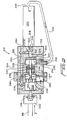
- a new and improved fluidic connector for use in convection with a pneumatically-operated fastener-driving tool so as to control the actuation of the tool and to effectively prevent the inadvertent or accidental actuation thereof, is disclosed and is generally indicated by the reference character 10.
- the fluidic connector 10 is seen to comprise a housing 12 wherein an upstream end portion thereof, as considered in the direction of the incoming air flow F, has an integral male quick connect/disconnect fitting 14 formed thereon, while a downstream end portion of the housing 12 has a female quick connect/disconnect fitting 16 integrally formed therein.
- the female fitting 20 of the air supply hose 18 is operatively, structurally and fluidically connected to the male fitting 14 of the fluidic connector 10 while the male fitting 22 of the fastener-driving tool 24 is operatively, structurally, and fluidically connected to the female fitting 16 of the fluidic connector 10.
- the fluidic connector housing 12 is provided with a first upstream axially oriented bore 26 that defines a first axially oriented entrance fluid or port 28 which is fluidically connected to the male fitting end portion 14 of the fluidic connecter 10, and a second downstream axially oriented bore 30 that defines a second axially oriented fluid conduit 32 which is fluidically connected to the female fitting 16 of the fluidic connector 10.
- a valve assembly 34 is operatively, structurally, and fluidically interposed between the first and second axial bores 26,30 and the first entrance and second exhaust fluid conduits 28, 32 thereof, and it is seen that the valve assembly 34 comprises a first external cylinder housing 36 and a second internal cylinder housing or block 38 fixedly mounted within the first external cylinder housing 36.
- a first piston member 40 is movably disposed within the second internal cylinder housing or block 38 and has a pair of first and second piston rods 42,44, respectively, which extend in oppositely oriented axial directions through oppositely disposed end walls 46,48 of the second internal cylinder housing or block 38.
- the opposite distal or free end portions of the piston rods 42,44 have piston members 50,52 fixedly mounted thereon such that the piston members 50,52 are reciprocally movable within piston chambers 54,56 which are respectively defined between end walls 58,60 of the first external cylinder housing 36 and the end walls 46,48 of the second internal cylindrical housing or block 38.
- a coil spring member 62 is disposed within a (second) right chamber 64, of the second cylinder housing or block 38, as defined between the piston member 40 and the right end wall 48 of the cylinder housing or block 38 so as to be coaxially disposed around the piston rod 44.
- a (first) left chamber 66 of cylinder housing or block 38 is similarly defined between the piston member 40 and the left end wall 46 of the cylinder housing or block 38, and a hydraulic fluid 68 is disposed within the left cylinder chamber 66.
- the piston member 40 is provided with a plurality of axially oriented apertures or bores 70 defined therethrough which permit fluidic communication of the hydraulic fluid 68 between the left and right cylinder housing Chambers 66,64, the significance of which will be more fully discussed hereinafter. It can thus be appreciated that the coil spring member 62 always tends to bias the piston member 40 toward the left as viewed in FIGURE 1 such that the hydraulic fluid 68 disposed within the left cylinder chamber 66 will be forced through the apertures or holes 70 and into the right cylinder chamber 64. It has to be noted that piston members 50, 40 and 52 will be designated first, second and third piston members in the attached claims, according to their introduction therein.
- a first end portion of a first radially oriented bore 72 is fluidically connected to the (first) piston chamber 54
- a first end portion of a second radially oriented bore 76, defining a fluid conduit 78 is fluidically connected to the fluid conduit 32 defined within the second axial bore 30
- a third axially oriented bore 80 defining a fluid conduit 82, fluidically interconnects second end portions of the radially oriented fluid conduits 74,78, the open end of the axial bore 80 being capped in effect by means of a suitable plug 84.
- a fluid conduit or flow path for the incoming air from air supply hose 18 to the tool 24 is able to be defined by means of first axial fluid conduit 28, piston chamber 54, first radial fluid conduit 74, third axial fluid conduit 82, second radial fluid conduit 78, and second axial fluid conduit 32.
- a manual actuator ring 86 is operatively connected to piston rod 42 by means of a connector rod 88 and is adapted to be slidably mounted upon the connector housing 12 in the direction noted by the arrow S.
- the manual actuator ring 86 is disposed at an extreme leftward position as a result of the biasing force or influence of the coil spring 62 acting upon the piston member 40 thereby forcing the piston member 40 into engagement with the left end wall 46 of the cylinder housing or block 38, the piston 50 will in effect block the fluid flow of the incoming supply air from fluid conduit 28 into fluid conduit 74 whereby the tool 24 cannot be fired.
- the tool 24 will initially be operatively connected to the connector housing 12 as a result of the mating of the male and female quick connect/disconnect mechanisms 22,16, and the connector housing 12 will likewise be operatively connected to the air supply hose 18 as a result of the mating of the male and female quick connect/disconnect mechanisms 14,20.
- the tool 24 will then be engaged with the workpiece or substrate, not shown, into which the fastener is to be driven such that a nosepiece portion, also not shown, of the tool 24 will be moved to a tool-enabling position or state.
- the tool 24 will not as yet in fact be enabled because the manual actuator ring 86 is initially disposed at its extreme leftward position at which piston 50 covers the entrance to fluid conduit 74 such that incoming air from air supply hose 18 cannot be transmitted to the tool 24 as has been discussed hereinbefore.
- the tool 24 will generate exhaust which is conducted toward a tool exhaust port 90 of the tool 24 as denoted by means of the arrow E.
- one end of an exhaust conduit 92 is fluidically connected to the exhaust port 90 while the opposite end of the exhaust conduit 92 is fluidically connected to the piston chamber 56 through means of an inlet port 94 defined within the connector housing 12 and a suitable quick connect and disconnect exhaust fitting 96.
- the tool 24 can be repetitively removed from its engaged position in contact with a workpiece or substrate so as to perform, for example, the discharge of fasteners in accordance with the aforenoted "bump-firing" mode of operation wherein, as a result of the tool firing trigger or mechanism being constantly activated or depressed, and the nosepiece portion of the tool, not shown, being intermittently engaged with the workpiece or substrate, the manual actuator ring 86 will be maintained at its extreme right position so as to constantly enable the firing of the tool 24 as desired.
- a one-way check valve 98 is mounted within the connector housing 12 and is fluidically connected to the piston chamber 56 by means of a radial bore 100. In this manner, if the tool 24 is repetitively fired in a rapid-fire mode whereby it is possible that the pressure attendant the exhaust impulses, as transmitted into piston chamber 56 from the tool exhaust port 90, becomes excessive, such excessive pressure car be relieved.
- piston 40 encounters a predetermined amount of resistance as determined by means of the viscosity of the hydraulic fluid 68, the number of through-apertures 70 formed within the piston 40, and the size of each through-aperture 70 within the piston 40. Accordingly, such aforenoted factors comprising the viscosity of the hydraulic fluid 68, and the number and size of the through-apertures 70 defined within the piston 40, predetermine the speed at which the hydraulic fluid 68 will pass through the apertures 70 of the piston 40 and the corresponding speed at which piston 40 will be able to be moved toward the left as seen in FIGURE 1.
- piston 52 Concomitant with the aforenoted termination of the air flow into fluid conduit 74 by means of the piston 50 covering the entrance to fluid conduit 74, piston 52 has another piston rod 102 integrally connected thereto which is also disposed within the axial bore 30 and accordingly, as piston 52 moves toward the left, piston rod 102 uncovers a connector drain port 104 whereby any residual air within the tool 24 is discharged and the tool 24 is ensured to be absolutely disabled.
- the tool 24 will not fine and therefore will not present a safety hazard to the operator or other personnel. Accordingly, in order to again place the tool 24 within an enabling firing mode, the manual actuator ring 86 must again be manually moved to the extreme right position.
- FIGURE 2 a modified second embodiment of a fluidic connector, similar to the fluidic connector 10 illustrated in FIGURE 1, is disclosed and is generally indicated by the reference character 210.
- the reference character 210 In view of the similarities between the first and second embodiments of the fluidic connectors 10,210, a detailed description of the second embodiment 210 will not be set forth for brevity reasons, and the discussion will be directed toward only the differences comprising the embodiments.
- the various structural components of the fluidic connector 210 which correspond to those structural components of the fluidic connector 10 will be designated by similar reference characters, however, the reference characters will be within the 200 and 300 series.
- piston 250 is provided with a plurality of through-bores or apertures 306 such that the incoming supply air does not act upon piston 250 with any significant force. The air can thus pass through bores or apertures 306 and impact upon the cylinder housing or block 238, however, since the cylinder housing or block 238 is fixed, such air pressure has no significant effect upon the operation of the system.
- the fluid flow from part 278, of the fluid conduit will in fact be sufficient to provide a fluid flow path from the connection means 214 to the (third) piston 252 for the supply air to impact against the piston 202 and to cause movement of the piston rod 302, piston 252, piston 240, and piston 250 toward the left whereupon when piston 250 covers the entrance into fluid conduit 274, and when piston rod 302 uncovers the drain conduit 304, the tool 224 is disabled.
- spring 62 as disclosed within the fluidic connector 10, has been able to be eliminated, and it is appreciated that the incoming supply air serves in effect as a pneumatic spring so as to effectively return or bias the entire piston assembly toward its extreme left tool-disabling position.
- a new and improved fluidic connector which is an independent adjunct to a pneumatic tool and is adapted to be fluidically interposed between an air supply hose and a fitting of the pneumatic tool.
- the connector comprises a manual ring actuator which is operatively connected to a piston-type valve member so as to permit air to be conducted to the tool when the manual ring actuator is manually moved to an extreme position. Consequently, when the tool firing trigger is activated and depressed, and the tool nosepiece is engaged with a workpiece or substrate into which the fasteners are to be driven, the tool will be enabled and can be fired.
- Exhaust generated from each fastener firing operation or cycle maintains the piston-type valve member at the desired position so as to permit the incoming air supply to reach the tool, however, if the tool is not fired for a predetermined period of time, the piston-type valve member is moved to a CLOSED position under a spring-biasing or pneumatic biasing force thereby disabling the tool even if the tool firing trigger and nosepiece are both activated or depressed. Enablement of the tool is only again achieved by moving the manual ring actuator to the extreme position. The disabling of the tool therefore prevents the inadvertent or accidental firing of the tool.
Landscapes
- Engineering & Computer Science (AREA)
- Mechanical Engineering (AREA)
- Physics & Mathematics (AREA)
- Fluid Mechanics (AREA)
- General Engineering & Computer Science (AREA)
- Analytical Chemistry (AREA)
- Chemical & Material Sciences (AREA)
- Portable Nailing Machines And Staplers (AREA)
- Processing Of Terminals (AREA)
- Self-Closing Valves And Venting Or Aerating Valves (AREA)
- Percussive Tools And Related Accessories (AREA)
- Quick-Acting Or Multi-Walled Pipe Joints (AREA)
- Fluid-Pressure Circuits (AREA)
Applications Claiming Priority (2)
| Application Number | Priority Date | Filing Date | Title |
|---|---|---|---|
| US943656 | 2001-08-31 | ||
| US09/943,656 US6523621B1 (en) | 2001-08-31 | 2001-08-31 | Delay-interruption connector for pneumatic tool |
Publications (3)
| Publication Number | Publication Date |
|---|---|
| EP1293301A2 true EP1293301A2 (de) | 2003-03-19 |
| EP1293301A3 EP1293301A3 (de) | 2003-08-13 |
| EP1293301B1 EP1293301B1 (de) | 2006-07-19 |
Family
ID=25480036
Family Applications (1)
| Application Number | Title | Priority Date | Filing Date |
|---|---|---|---|
| EP02292117A Expired - Lifetime EP1293301B1 (de) | 2001-08-31 | 2002-08-28 | Verbinder für den Pneumatikanschluss eines pneumatischen Werkzeugs und dessen Kombination |
Country Status (12)
| Country | Link |
|---|---|
| US (1) | US6523621B1 (de) |
| EP (1) | EP1293301B1 (de) |
| JP (1) | JP2003159665A (de) |
| KR (1) | KR20030019856A (de) |
| CN (1) | CN1406718A (de) |
| AT (1) | ATE333345T1 (de) |
| AU (1) | AU2002300673B2 (de) |
| DE (1) | DE60213172T2 (de) |
| DK (1) | DK1293301T3 (de) |
| MX (1) | MXPA02008404A (de) |
| NZ (1) | NZ521021A (de) |
| TW (1) | TWI221175B (de) |
Families Citing this family (17)
| Publication number | Priority date | Publication date | Assignee | Title |
|---|---|---|---|---|
| US6523621B1 (en) * | 2001-08-31 | 2003-02-25 | Illinois Tool Works Inc. | Delay-interruption connector for pneumatic tool |
| FR2868862B1 (fr) * | 2004-04-09 | 2006-06-23 | Somfy Soc Par Actions Simplifi | Procede de fonctionnement d'un actionneur de volet roulant et dispositif pour sa mise en oeuvre |
| US20070102177A1 (en) * | 2005-11-09 | 2007-05-10 | Lee Omar P | Combined torque indicator and regulator for pneumatically-operated hand tool |
| US7373992B2 (en) * | 2006-07-26 | 2008-05-20 | Exhaust Technologies, Inc. | Automatic pressure regulating valve for a pneumatic tool |
| US8549984B2 (en) * | 2009-12-28 | 2013-10-08 | Fisher Controls International, Llc | Apparatus to increase a force of an actuator having an override apparatus |
| WO2014028578A2 (en) * | 2012-08-14 | 2014-02-20 | Stanley Black & Decker, Inc. | Identification device attachments for pneumatic devices |
| US20140360744A1 (en) * | 2013-06-05 | 2014-12-11 | Campbell Hausfeld / Scott Fetzer Company | Handheld pneumatic tools having pressure regulator |
| CN104534141B (zh) * | 2014-12-09 | 2017-01-11 | 南昌大学 | 节水中间阀 |
| EP3090836A1 (de) * | 2015-05-06 | 2016-11-09 | Illinois Tool Works Inc. | Eintreibwerkzeug mit verbesserter sicherheitseinrichtung |
| CN105020198B (zh) * | 2015-08-14 | 2017-03-08 | 孙晓君 | 一种液压作动器及复合摇臂 |
| CA2945276C (en) * | 2015-10-16 | 2024-05-28 | Brian Keith Orchard | Deck clip magazine |
| JP6575679B2 (ja) * | 2016-04-28 | 2019-09-18 | 工機ホールディングス株式会社 | 打込機 |
| CN105889573B (zh) * | 2016-06-24 | 2018-04-17 | 浙江博恩自控阀门有限公司 | 安装于气动执行器的控气阀 |
| WO2019171809A1 (ja) * | 2018-03-09 | 2019-09-12 | 工機ホールディングス株式会社 | 打込機及び切替機構 |
| TWI684719B (zh) * | 2019-02-27 | 2020-02-11 | 陳文彬 | 流體控制裝置 |
| WO2022067256A1 (en) | 2020-09-28 | 2022-03-31 | Black & Deck, Inc. | Fastener driving tool trigger assembly |
| DE102021103015B3 (de) * | 2021-02-09 | 2022-04-21 | Oetiker Schweiz Ag | Sicherheitsventil für ein pneumatisch betätigbares Werkzeug |
Family Cites Families (14)
| Publication number | Priority date | Publication date | Assignee | Title |
|---|---|---|---|---|
| US3033236A (en) | 1959-05-14 | 1962-05-08 | George E Rayman | Torque timing system |
| US3732934A (en) | 1969-08-28 | 1973-05-15 | Aro Corp | Fluid-driven tool with built-in work control mechanism |
| US3580285A (en) | 1969-08-28 | 1971-05-25 | Aro Corp | Work control device for fluid driven apparatus |
| US3934657A (en) * | 1974-08-01 | 1976-01-27 | Thor Power Tool Company | Dual safety control means for a power tool |
| US3970110A (en) * | 1975-02-06 | 1976-07-20 | Chicago Pneumatic Tool Company | Safety inlet air valve control arrangement for air powered hand held tool |
| US3964659A (en) * | 1975-03-12 | 1976-06-22 | Senco Products, Inc. | Safety firing control means for a fluid operated tool |
| US4243111A (en) * | 1979-01-31 | 1981-01-06 | Ingersoll-Rand Company | Automatic shut-off valve for power tools |
| DE3142237A1 (de) * | 1981-10-24 | 1983-05-05 | Signode Corp., Glenview, Ill. | Pneumatisch betaetigbares befestigungsmitteleintreibgeraet |
| US4834131A (en) * | 1987-11-10 | 1989-05-30 | Duo-Fast Corporation | Safety system for pneumatic tools |
| US4817667A (en) * | 1988-02-03 | 1989-04-04 | Dresser Industries, Inc. | Metering regulator for pneumatic tools |
| DE4243068C2 (de) | 1992-12-18 | 2003-06-26 | Cooper Power Tools Gmbh & Co | Druckluftschrauber, insbesondere Puls- oder Drehschrauber |
| US5531279A (en) | 1994-04-12 | 1996-07-02 | Indresco Inc. | Sensor impulse unit |
| US6161628A (en) * | 2000-04-28 | 2000-12-19 | Q.C. Witness Int. Co., Ltd. | Pneumatic tool |
| US6523621B1 (en) * | 2001-08-31 | 2003-02-25 | Illinois Tool Works Inc. | Delay-interruption connector for pneumatic tool |
-
2001
- 2001-08-31 US US09/943,656 patent/US6523621B1/en not_active Expired - Lifetime
-
2002
- 2002-07-24 JP JP2002215326A patent/JP2003159665A/ja active Pending
- 2002-07-29 KR KR1020020044660A patent/KR20030019856A/ko not_active Withdrawn
- 2002-08-16 TW TW091118493A patent/TWI221175B/zh not_active IP Right Cessation
- 2002-08-16 CN CN02130557A patent/CN1406718A/zh active Pending
- 2002-08-21 AU AU2002300673A patent/AU2002300673B2/en not_active Ceased
- 2002-08-27 NZ NZ521021A patent/NZ521021A/en not_active IP Right Cessation
- 2002-08-28 AT AT02292117T patent/ATE333345T1/de not_active IP Right Cessation
- 2002-08-28 DK DK02292117T patent/DK1293301T3/da active
- 2002-08-28 MX MXPA02008404A patent/MXPA02008404A/es unknown
- 2002-08-28 DE DE60213172T patent/DE60213172T2/de not_active Expired - Lifetime
- 2002-08-28 EP EP02292117A patent/EP1293301B1/de not_active Expired - Lifetime
Also Published As
| Publication number | Publication date |
|---|---|
| ATE333345T1 (de) | 2006-08-15 |
| CN1406718A (zh) | 2003-04-02 |
| NZ521021A (en) | 2003-09-26 |
| DE60213172T2 (de) | 2007-07-12 |
| KR20030019856A (ko) | 2003-03-07 |
| TWI221175B (en) | 2004-09-21 |
| JP2003159665A (ja) | 2003-06-03 |
| EP1293301B1 (de) | 2006-07-19 |
| AU2002300673B2 (en) | 2006-01-05 |
| DK1293301T3 (da) | 2006-11-20 |
| DE60213172D1 (de) | 2006-08-31 |
| EP1293301A3 (de) | 2003-08-13 |
| MXPA02008404A (es) | 2003-03-05 |
| US6523621B1 (en) | 2003-02-25 |
Similar Documents
| Publication | Publication Date | Title |
|---|---|---|
| EP1293301B1 (de) | Verbinder für den Pneumatikanschluss eines pneumatischen Werkzeugs und dessen Kombination | |
| US5517898A (en) | Pneumatic cylinder utilizing cushioning sleeves, quick exhaust valves and quick supply valves | |
| US6604664B2 (en) | Safe trigger with time delay for pneumatic fastener driving tools | |
| US5850961A (en) | Quick exhaust remote trigger valve for fastener driving tool | |
| US2706487A (en) | Release valves | |
| US4550643A (en) | Fastener driving tool | |
| US4263801A (en) | Hydraulic riveter | |
| KR970701645A (ko) | 스프링 챔버가 차단된 유체작동식 액츄에이터(fluid-operated brake actuator with spring chamber isolation) | |
| US4282896A (en) | Pilot operated check valve | |
| US11148156B2 (en) | Switching valve and intermittent air blow gun | |
| EP3396174A1 (de) | Ventilvorrichtung | |
| US4759504A (en) | Dump control and valve | |
| US2268733A (en) | Pneumatic safety control for presses | |
| US2619112A (en) | Pressure relief valve | |
| US5325763A (en) | Internal check valve | |
| US6604547B1 (en) | Double valve with cross exhaust | |
| US5353683A (en) | Pneumatic transformer | |
| US3696835A (en) | Control valve | |
| JPH0553994B2 (de) | ||
| US5159987A (en) | Valve construction for automatic shut-off screwdrivers and the like | |
| US3722542A (en) | Pressure biased power take off valve | |
| US5114215A (en) | Brake system | |
| CN218991852U (zh) | 一种连续压接液压工具的液压泵 | |
| RU2066016C1 (ru) | Быстроразъемное соединение трубопроводов | |
| GB2103727A (en) | Poppet valve arrangement and impact tool operationally controlled thereby |
Legal Events
| Date | Code | Title | Description |
|---|---|---|---|
| PUAI | Public reference made under article 153(3) epc to a published international application that has entered the european phase |
Free format text: ORIGINAL CODE: 0009012 |
|
| AK | Designated contracting states |
Kind code of ref document: A2 Designated state(s): AT BE BG CH CY CZ DE DK EE ES FI FR GB GR IE IT LI LU MC NL PT SE SK TR |
|
| AX | Request for extension of the european patent |
Extension state: AL LT LV MK RO SI |
|
| PUAL | Search report despatched |
Free format text: ORIGINAL CODE: 0009013 |
|
| AK | Designated contracting states |
Designated state(s): AT BE BG CH CY CZ DE DK EE ES FI FR GB GR IE IT LI LU MC NL PT SE SK TR |
|
| AX | Request for extension of the european patent |
Extension state: AL LT LV MK RO SI |
|
| RIC1 | Information provided on ipc code assigned before grant |
Ipc: 7F 15B 21/10 B Ipc: 7B 25C 1/00 A Ipc: 7B 25C 1/04 B |
|
| 17P | Request for examination filed |
Effective date: 20040213 |
|
| AKX | Designation fees paid |
Designated state(s): AT BE BG CH CY CZ DE DK EE ES FI FR GB GR IE IT LI LU MC NL PT SE SK TR |
|
| GRAP | Despatch of communication of intention to grant a patent |
Free format text: ORIGINAL CODE: EPIDOSNIGR1 |
|
| GRAS | Grant fee paid |
Free format text: ORIGINAL CODE: EPIDOSNIGR3 |
|
| GRAA | (expected) grant |
Free format text: ORIGINAL CODE: 0009210 |
|
| AK | Designated contracting states |
Kind code of ref document: B1 Designated state(s): AT BE BG CH CY CZ DE DK EE ES FI FR GB GR IE IT LI LU MC NL PT SE SK TR |
|
| PG25 | Lapsed in a contracting state [announced via postgrant information from national office to epo] |
Ref country code: IT Free format text: LAPSE BECAUSE OF FAILURE TO SUBMIT A TRANSLATION OF THE DESCRIPTION OR TO PAY THE FEE WITHIN THE PRESCRIBED TIME-LIMIT;WARNING: LAPSES OF ITALIAN PATENTS WITH EFFECTIVE DATE BEFORE 2007 MAY HAVE OCCURRED AT ANY TIME BEFORE 2007. THE CORRECT EFFECTIVE DATE MAY BE DIFFERENT FROM THE ONE RECORDED. Effective date: 20060719 Ref country code: CZ Free format text: LAPSE BECAUSE OF FAILURE TO SUBMIT A TRANSLATION OF THE DESCRIPTION OR TO PAY THE FEE WITHIN THE PRESCRIBED TIME-LIMIT Effective date: 20060719 Ref country code: CH Free format text: LAPSE BECAUSE OF FAILURE TO SUBMIT A TRANSLATION OF THE DESCRIPTION OR TO PAY THE FEE WITHIN THE PRESCRIBED TIME-LIMIT Effective date: 20060719 Ref country code: NL Free format text: LAPSE BECAUSE OF FAILURE TO SUBMIT A TRANSLATION OF THE DESCRIPTION OR TO PAY THE FEE WITHIN THE PRESCRIBED TIME-LIMIT Effective date: 20060719 Ref country code: FI Free format text: LAPSE BECAUSE OF FAILURE TO SUBMIT A TRANSLATION OF THE DESCRIPTION OR TO PAY THE FEE WITHIN THE PRESCRIBED TIME-LIMIT Effective date: 20060719 Ref country code: SK Free format text: LAPSE BECAUSE OF FAILURE TO SUBMIT A TRANSLATION OF THE DESCRIPTION OR TO PAY THE FEE WITHIN THE PRESCRIBED TIME-LIMIT Effective date: 20060719 Ref country code: AT Free format text: LAPSE BECAUSE OF FAILURE TO SUBMIT A TRANSLATION OF THE DESCRIPTION OR TO PAY THE FEE WITHIN THE PRESCRIBED TIME-LIMIT Effective date: 20060719 Ref country code: BE Free format text: LAPSE BECAUSE OF FAILURE TO SUBMIT A TRANSLATION OF THE DESCRIPTION OR TO PAY THE FEE WITHIN THE PRESCRIBED TIME-LIMIT Effective date: 20060719 Ref country code: LI Free format text: LAPSE BECAUSE OF FAILURE TO SUBMIT A TRANSLATION OF THE DESCRIPTION OR TO PAY THE FEE WITHIN THE PRESCRIBED TIME-LIMIT Effective date: 20060719 |
|
| REG | Reference to a national code |
Ref country code: GB Ref legal event code: FG4D |
|
| REG | Reference to a national code |
Ref country code: CH Ref legal event code: EP |
|
| REG | Reference to a national code |
Ref country code: IE Ref legal event code: FG4D |
|
| PG25 | Lapsed in a contracting state [announced via postgrant information from national office to epo] |
Ref country code: IE Free format text: LAPSE BECAUSE OF NON-PAYMENT OF DUE FEES Effective date: 20060828 |
|
| PG25 | Lapsed in a contracting state [announced via postgrant information from national office to epo] |
Ref country code: MC Free format text: LAPSE BECAUSE OF NON-PAYMENT OF DUE FEES Effective date: 20060831 |
|
| REF | Corresponds to: |
Ref document number: 60213172 Country of ref document: DE Date of ref document: 20060831 Kind code of ref document: P |
|
| PG25 | Lapsed in a contracting state [announced via postgrant information from national office to epo] |
Ref country code: BG Free format text: LAPSE BECAUSE OF FAILURE TO SUBMIT A TRANSLATION OF THE DESCRIPTION OR TO PAY THE FEE WITHIN THE PRESCRIBED TIME-LIMIT Effective date: 20061019 Ref country code: SE Free format text: LAPSE BECAUSE OF FAILURE TO SUBMIT A TRANSLATION OF THE DESCRIPTION OR TO PAY THE FEE WITHIN THE PRESCRIBED TIME-LIMIT Effective date: 20061019 |
|
| PG25 | Lapsed in a contracting state [announced via postgrant information from national office to epo] |
Ref country code: ES Free format text: LAPSE BECAUSE OF FAILURE TO SUBMIT A TRANSLATION OF THE DESCRIPTION OR TO PAY THE FEE WITHIN THE PRESCRIBED TIME-LIMIT Effective date: 20061030 |
|
| REG | Reference to a national code |
Ref country code: DK Ref legal event code: T3 |
|
| PG25 | Lapsed in a contracting state [announced via postgrant information from national office to epo] |
Ref country code: PT Free format text: LAPSE BECAUSE OF FAILURE TO SUBMIT A TRANSLATION OF THE DESCRIPTION OR TO PAY THE FEE WITHIN THE PRESCRIBED TIME-LIMIT Effective date: 20061219 |
|
| NLV1 | Nl: lapsed or annulled due to failure to fulfill the requirements of art. 29p and 29m of the patents act | ||
| ET | Fr: translation filed | ||
| PLBE | No opposition filed within time limit |
Free format text: ORIGINAL CODE: 0009261 |
|
| STAA | Information on the status of an ep patent application or granted ep patent |
Free format text: STATUS: NO OPPOSITION FILED WITHIN TIME LIMIT |
|
| 26N | No opposition filed |
Effective date: 20070420 |
|
| PG25 | Lapsed in a contracting state [announced via postgrant information from national office to epo] |
Ref country code: GR Free format text: LAPSE BECAUSE OF FAILURE TO SUBMIT A TRANSLATION OF THE DESCRIPTION OR TO PAY THE FEE WITHIN THE PRESCRIBED TIME-LIMIT Effective date: 20061020 |
|
| PG25 | Lapsed in a contracting state [announced via postgrant information from national office to epo] |
Ref country code: EE Free format text: LAPSE BECAUSE OF FAILURE TO SUBMIT A TRANSLATION OF THE DESCRIPTION OR TO PAY THE FEE WITHIN THE PRESCRIBED TIME-LIMIT Effective date: 20060719 |
|
| PG25 | Lapsed in a contracting state [announced via postgrant information from national office to epo] |
Ref country code: LU Free format text: LAPSE BECAUSE OF NON-PAYMENT OF DUE FEES Effective date: 20060828 Ref country code: TR Free format text: LAPSE BECAUSE OF FAILURE TO SUBMIT A TRANSLATION OF THE DESCRIPTION OR TO PAY THE FEE WITHIN THE PRESCRIBED TIME-LIMIT Effective date: 20060719 |
|
| PG25 | Lapsed in a contracting state [announced via postgrant information from national office to epo] |
Ref country code: CY Free format text: LAPSE BECAUSE OF FAILURE TO SUBMIT A TRANSLATION OF THE DESCRIPTION OR TO PAY THE FEE WITHIN THE PRESCRIBED TIME-LIMIT Effective date: 20060719 |
|
| PGFP | Annual fee paid to national office [announced via postgrant information from national office to epo] |
Ref country code: GB Payment date: 20110825 Year of fee payment: 10 |
|
| GBPC | Gb: european patent ceased through non-payment of renewal fee |
Effective date: 20120828 |
|
| PG25 | Lapsed in a contracting state [announced via postgrant information from national office to epo] |
Ref country code: GB Free format text: LAPSE BECAUSE OF NON-PAYMENT OF DUE FEES Effective date: 20120828 |
|
| REG | Reference to a national code |
Ref country code: FR Ref legal event code: PLFP Year of fee payment: 14 |
|
| PGFP | Annual fee paid to national office [announced via postgrant information from national office to epo] |
Ref country code: DE Payment date: 20150827 Year of fee payment: 14 Ref country code: DK Payment date: 20150825 Year of fee payment: 14 |
|
| PGFP | Annual fee paid to national office [announced via postgrant information from national office to epo] |
Ref country code: FR Payment date: 20150817 Year of fee payment: 14 |
|
| REG | Reference to a national code |
Ref country code: DE Ref legal event code: R119 Ref document number: 60213172 Country of ref document: DE |
|
| REG | Reference to a national code |
Ref country code: DK Ref legal event code: EBP Effective date: 20160831 |
|
| REG | Reference to a national code |
Ref country code: FR Ref legal event code: ST Effective date: 20170428 |
|
| PG25 | Lapsed in a contracting state [announced via postgrant information from national office to epo] |
Ref country code: DK Free format text: LAPSE BECAUSE OF NON-PAYMENT OF DUE FEES Effective date: 20160831 Ref country code: DE Free format text: LAPSE BECAUSE OF NON-PAYMENT OF DUE FEES Effective date: 20170301 Ref country code: FR Free format text: LAPSE BECAUSE OF NON-PAYMENT OF DUE FEES Effective date: 20160831 |