EP1293287A2 - Verfahren und Vorrichtung zur Laserbearbeitung mittels eines Laserstrahles - Google Patents
Verfahren und Vorrichtung zur Laserbearbeitung mittels eines Laserstrahles Download PDFInfo
- Publication number
- EP1293287A2 EP1293287A2 EP02017219A EP02017219A EP1293287A2 EP 1293287 A2 EP1293287 A2 EP 1293287A2 EP 02017219 A EP02017219 A EP 02017219A EP 02017219 A EP02017219 A EP 02017219A EP 1293287 A2 EP1293287 A2 EP 1293287A2
- Authority
- EP
- European Patent Office
- Prior art keywords
- laser beam
- spot
- main axes
- laser
- reflector
- Prior art date
- Legal status (The legal status is an assumption and is not a legal conclusion. Google has not performed a legal analysis and makes no representation as to the accuracy of the status listed.)
- Withdrawn
Links
Images
Classifications
-
- B—PERFORMING OPERATIONS; TRANSPORTING
- B23—MACHINE TOOLS; METAL-WORKING NOT OTHERWISE PROVIDED FOR
- B23K—SOLDERING OR UNSOLDERING; WELDING; CLADDING OR PLATING BY SOLDERING OR WELDING; CUTTING BY APPLYING HEAT LOCALLY, e.g. FLAME CUTTING; WORKING BY LASER BEAM
- B23K26/00—Working by laser beam, e.g. welding, cutting or boring
- B23K26/02—Positioning or observing the workpiece, e.g. with respect to the point of impact; Aligning, aiming or focusing the laser beam
- B23K26/06—Shaping the laser beam, e.g. by masks or multi-focusing
- B23K26/0604—Shaping the laser beam, e.g. by masks or multi-focusing by a combination of beams
- B23K26/0613—Shaping the laser beam, e.g. by masks or multi-focusing by a combination of beams having a common axis
-
- B—PERFORMING OPERATIONS; TRANSPORTING
- B23—MACHINE TOOLS; METAL-WORKING NOT OTHERWISE PROVIDED FOR
- B23K—SOLDERING OR UNSOLDERING; WELDING; CLADDING OR PLATING BY SOLDERING OR WELDING; CUTTING BY APPLYING HEAT LOCALLY, e.g. FLAME CUTTING; WORKING BY LASER BEAM
- B23K26/00—Working by laser beam, e.g. welding, cutting or boring
- B23K26/02—Positioning or observing the workpiece, e.g. with respect to the point of impact; Aligning, aiming or focusing the laser beam
- B23K26/06—Shaping the laser beam, e.g. by masks or multi-focusing
- B23K26/0604—Shaping the laser beam, e.g. by masks or multi-focusing by a combination of beams
-
- B—PERFORMING OPERATIONS; TRANSPORTING
- B23—MACHINE TOOLS; METAL-WORKING NOT OTHERWISE PROVIDED FOR
- B23K—SOLDERING OR UNSOLDERING; WELDING; CLADDING OR PLATING BY SOLDERING OR WELDING; CUTTING BY APPLYING HEAT LOCALLY, e.g. FLAME CUTTING; WORKING BY LASER BEAM
- B23K26/00—Working by laser beam, e.g. welding, cutting or boring
- B23K26/02—Positioning or observing the workpiece, e.g. with respect to the point of impact; Aligning, aiming or focusing the laser beam
- B23K26/06—Shaping the laser beam, e.g. by masks or multi-focusing
- B23K26/067—Dividing the beam into multiple beams, e.g. multi-focusing
-
- B—PERFORMING OPERATIONS; TRANSPORTING
- B23—MACHINE TOOLS; METAL-WORKING NOT OTHERWISE PROVIDED FOR
- B23K—SOLDERING OR UNSOLDERING; WELDING; CLADDING OR PLATING BY SOLDERING OR WELDING; CUTTING BY APPLYING HEAT LOCALLY, e.g. FLAME CUTTING; WORKING BY LASER BEAM
- B23K26/00—Working by laser beam, e.g. welding, cutting or boring
- B23K26/02—Positioning or observing the workpiece, e.g. with respect to the point of impact; Aligning, aiming or focusing the laser beam
- B23K26/06—Shaping the laser beam, e.g. by masks or multi-focusing
- B23K26/073—Shaping the laser spot
Definitions
- the invention relates to a method intended for laser processing by means of a laser beam, by which an ideal shape deviating from a point-symmetrical shape in particular Spot area is corrected. Furthermore, the invention relates to a device for Execution of the procedure.
- the spot area-related deviation can be caused by correction values in the control program be compensated for, for example, depending on the feed direction to be able to set a corrected trajectory.
- correction values in the control program be compensated for, for example, depending on the feed direction to be able to set a corrected trajectory.
- the object of the invention is therefore to create a method by which a simple correction or the point symmetry of the spot area can be brought about.
- the method should be without mechanical actuators or changes in the Control program can be carried out.
- a device for performing the Procedure are created.
- the first-mentioned object is achieved according to the invention with a method according to the features of claim 1 solved.
- the first spot surface has a second, opposite to this rotated around the optical axis spot surface is superimposed by the laser beam first into a first laser beam and a second, the second spot area forming laser beam and split after reflection on one opposite Main axes inclined reflector, the surface normal of which is at an angle with the main axes between 0 and 90 °, is combined to form the common laser beam (3).
- the first spot area becomes a second, in particular congruent, spot area superimposed, the second spot area compared to the first spot area around the optical Axis is rotated.
- the second object of the invention is a device which can be used in laser processing for correcting a deviation from an ideal shape in the direction of two main axes
- creating a spot area of a laser beam is achieved by means of a splitting element to split off the second laser beam from the beam path of the common one Laser beam in the direction of a reflector inclined with respect to the main axes, the Surface normal with the main axes encloses an angle between 0 and 90 °, and a Merging element for merging a second laser beam with a second one optical axis rotated spot area with the first laser beam to the common laser beam, solved by superimposing the two congruent spot areas in particular a point-symmetrical total area is limited, which is largely independent from a feed direction of the device.
- the second laser beam is the first shared beam path of the first laser beam and split in the direction of the reflector directed. From there, the laser beam arrives at the union element, through which the first and second laser beams in the direction of the optical axis to the common one Laser beam can be combined. Deviating due to the deflection of the second laser beam of the main axes is a rotation of the different axis of the Spot area reached, so that the two spot areas of the first and the second laser beam are superimposed on one another.
- a further particularly expedient modification of the present invention is thereby achieved that the reflector is designed as a highly reflective plane mirror, whereby a largely lossless and wear-free deflection of the laser beam is ensured becomes.
- a particularly advantageous embodiment of the invention is achieved in that the Surface normal of the reflector encloses an angle of 45 ° with the main axes.
- the second spot area is rotated by 90 ° relative to the first spot area, whereby there is an essentially point-symmetrical boundary surface of the superimposed spot areas results.
- the superimposed spot area is therefore ideal for processing of a workpiece because it is essentially independent of the feed direction with laser processing.
- the Aus or union element can be formed by a semi-transparent mirror his.
- an embodiment of the present invention is also particularly practical. in which the splitting element and / or combining element has a polarizer. This makes a possible with the coupling and decoupling of the second laser beam associated loss of performance largely prevented.
- the total intensity of the two laser beams This corresponds approximately to the intensity of the source beam before it is coupled out of the second laser beam.
- the device is pivotable about the optical axis. This allows the relative angle between the superimposed spot areas by rotating or by defining them in different ways Angular positions with respect to the optical axis are set to the desired dimension become. In particular, a 90 ° angle can already be set by the manufacturer, through which the spot areas are superimposed to a point-symmetrical total area.
- Another particularly expedient embodiment of the invention is also created if the device is arranged in the beam path in front of the splitting element Has delay plates. This is particularly due to a rotation around the optical axis adjustable so that even with unpolarized or only partially polarized Light a matching intensity of the two laser beams is adjustable.
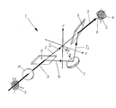
- the invention allows various embodiments. To further clarify its basic principle, one of them is shown in the drawing and is described below with reference to a perspective view of the device 1 according to the invention.
- a spot surface 2 of a common laser beam 3 is shown, the spot surface 2 having different power and / or angle distributions of the laser beam 3 in the direction of its main axes X and Y according to their oval geometry. Because of this asymmetrical power distribution in the focusing plane, a correction of the spot area 2 is necessary for laser processing by means of the laser beam 3, since otherwise the use of the laser leads to different results depending on the feed direction.
- the laser beam 3 is split into a first laser beam 4 and a second laser beam 5 following an optical axis 9 by means of a splitting element 6 designed as a polarizer, and after reflection on a reflector 7 designed as a mirror, also using a polarizer Union element 8 coupled back into the beam path of the first laser beam 3 along an optical axis 9.
- the reflector 7 is arranged relative to the main axes X, Y such that the surface normal N of the reflector 7 encloses an angle ⁇ with the main axis X. This angle ⁇ leads to a relative rotation of a second spot area 10 with respect to the spot area 2 of the first laser beam 3 with the angle 2 ⁇ .
- the device 1 is arranged to be pivotable about the optical axis 9, so that any superimposition of the two spot surfaces 2, 10 can be set.
- a retardation plate 11 Arranged in the beam path in front of the splitting element 6 is a retardation plate 11, which can be adjusted in particular by rotating about the optical axis 9 such that even with unpolarized or only partially polarized laser light, a corresponding intensity I 1 , I 2 of the two laser beams 4, 5 is adjustable.
Landscapes
- Physics & Mathematics (AREA)
- Optics & Photonics (AREA)
- Engineering & Computer Science (AREA)
- Plasma & Fusion (AREA)
- Mechanical Engineering (AREA)
- Laser Beam Processing (AREA)
Abstract
Description
Claims (8)
- Ein zur Laserbearbeitung mittels eines Laserstrahles (3) bestimmtes Verfahren, durch welches eine von einer insbesondere punktsymmetrischen Idealform abweichende Spotfläche (2) korrigiert wird, dadurch gekennzeichnet, daß der ersten Spotfläche (2) eine zweite, gegenüber dieser um die optische Achse (9) gedrehte Spotfläche (10) überlagert wird, indem der Laserstrahl (3) zunächst in einen ersten Laserstrahl (5) und einen zweiten, die zweite Spotfläche (10) bildenden Laserstrahl (4) aufgespaltet und nach einer Reflexion an einem gegenüber den Hauptachsen (X, Y) geneigten Reflektor (7), dessen Flächennormale (N) mit den Hauptachsen (X, Y) einen Winkel zwischen 0 und 90° einschließt, zu dem gemeinsamen Laserstrahl (3) vereinigt wird.
- Verfahren nach Anspruch 1, dadurch gekennzeichnet, daß der zweite Laserstrahl (4) in einer von den Ebenen der Hauptachsen (X, Y) der ersten Spotfläche (2) abweichenden Richtung derart von dem zunächst gemeinsamen Laserstrahl (3) abgespaltet wird, daß die zweite Spotfläche (10) gegenüber der ersten Spotfläche (2) um die optische Achse (9) um 90° gedreht ist.
- Bei der Laserbearbeitung einsetzbare Vorrichtung (1) zur Korrektur einer in Richtung von zwei Hauptachsen (X, Y) von einer punktsymmetrischen Idealform abweichenden Spotfläche (2) eines Laserstrahles (3), gekennzeichnet durch ein Spaltungselement (6) zum Abspalten des zweiten Laserstrahles (4) aus dem Strahlengang des gemeinsamen Laserstrahles (3) in Richtung eines gegenüber den Hauptachsen (X, Y) geneigten Reflektors (7), dessen Flächennormale (N) mit den Hauptachsen (X, Y) einen Winkel zwischen 0 und 90° einschließt, und ein Vereinigungselement (8) zur Vereinigung eines zweiten Laserstrahls (4) mit einer zweiten, um eine optische Achse (9) gedrehten Spotfläche (10) mit dem ersten Laserstrahl (3) zu dem gemeinsamen Laserstrahl (3).
- Vorrichtung (1) nach Anspruch 3, dadurch gekennzeichnet, daß der Reflektor (7) als ein hochreflektierender Planspiegel ausgeführt ist.
- Vorrichtung (1) nach Anspruch 3 oder 4, dadurch gekennzeichnet, daß die Flächennormale (N) des Reflektors (7) mit den Hauptachsen (X, Y) einen Winkel von 45° einschließt.
- Vorrichtung (1) nach zumindest einem der Ansprüche 3 bis 5, dadurch gekennzeichnet, daß das Spaltungselement (6) und / oder Vereinigungselement (8) einen Polarisator aufweist.
- Vorrichtung (1) nach zumindest einem der Ansprüche 3 bis 6, dadurch gekennzeichnet, daß die Vorrichtung (1) um die optische Achse (9) schwenkbar ist.
- Vorrichtung (1) nach zumindest einem der Ansprüche 3 bis 7, dadurch gekennzeichnet, daß die Vorrichtung (1) ein im Strahlengang vor dem Spaltungselement (6) angeordnetes Verzögerungsplättchen (11) aufweist.
Applications Claiming Priority (2)
| Application Number | Priority Date | Filing Date | Title |
|---|---|---|---|
| DE10144521 | 2001-09-10 | ||
| DE10144521A DE10144521C1 (de) | 2001-09-10 | 2001-09-10 | Verfahren und Vorrichtung zur Laserbearbeitung mittels eines Laserstrahles |
Publications (2)
| Publication Number | Publication Date |
|---|---|
| EP1293287A2 true EP1293287A2 (de) | 2003-03-19 |
| EP1293287A3 EP1293287A3 (de) | 2005-03-30 |
Family
ID=7698501
Family Applications (1)
| Application Number | Title | Priority Date | Filing Date |
|---|---|---|---|
| EP02017219A Withdrawn EP1293287A3 (de) | 2001-09-10 | 2002-07-31 | Verfahren und Vorrichtung zur Laserbearbeitung mittels eines Laserstrahles |
Country Status (4)
| Country | Link |
|---|---|
| US (1) | US6627845B2 (de) |
| EP (1) | EP1293287A3 (de) |
| JP (1) | JP2003103391A (de) |
| DE (1) | DE10144521C1 (de) |
Cited By (2)
| Publication number | Priority date | Publication date | Assignee | Title |
|---|---|---|---|---|
| WO2008049389A1 (de) * | 2006-10-25 | 2008-05-02 | Lpkf Laser & Electronics Ag | Vorrichtung zur bearbeitung eines werkstücks mittels laserstrahlung |
| WO2015114032A1 (de) * | 2014-01-31 | 2015-08-06 | Trumpf Laser- Und Systemtechnik Gmbh | Laserbearbeitungsvorrichtung mit zwei unterschiedlichen teilstrahlen |
Families Citing this family (5)
| Publication number | Priority date | Publication date | Assignee | Title |
|---|---|---|---|---|
| US8053705B2 (en) * | 2005-09-07 | 2011-11-08 | Purdue Research Foundation | Laser assisted machining process with distributed lasers |
| US8604381B1 (en) | 2006-10-12 | 2013-12-10 | Purdue Research Foundation | Integrated laser material processing cell |
| KR20140091029A (ko) | 2011-10-31 | 2014-07-18 | 티코나 엘엘씨 | 레이저 직접 구조체 기판의 형성에 사용하기 위한 열가소성 조성물 |
| US9539681B2 (en) | 2011-11-30 | 2017-01-10 | Board Of Trustees Of Northern Illinois University | Laser assisted machining system for ceramics and hard materials |
| CN108326423B (zh) * | 2018-03-19 | 2020-02-04 | 深圳市恩兴实业有限公司 | 一种激光焊接工艺 |
Family Cites Families (9)
| Publication number | Priority date | Publication date | Assignee | Title |
|---|---|---|---|---|
| IT1144346B (it) * | 1981-05-08 | 1986-10-29 | Fiat Ricerche | Dispositivo per modificare e uniformare la distribuzione d intensita di un fascio laser di potenza |
| JPS60146214A (ja) * | 1984-01-11 | 1985-08-01 | Hitachi Ltd | 光線修正装置 |
| US4643538A (en) * | 1984-07-06 | 1987-02-17 | Storage Technology Partners Ii | Combined beam cross-section correcting, collimating and de-astigmatizing optical system |
| JPS6213291A (ja) * | 1985-07-10 | 1987-01-22 | Nec Corp | レ−ザ加工装置 |
| US5204516A (en) * | 1991-04-23 | 1993-04-20 | U.S. Philips Corporation | Planar optical scanning head having deficiency-correcting grating |
| DE4341553C1 (de) * | 1993-12-07 | 1995-04-27 | Fraunhofer Ges Forschung | Vorrichtung zum Homogenisieren der Lichtverteilung eines Laserstrahles |
| US6489589B1 (en) * | 1994-02-07 | 2002-12-03 | Board Of Regents, University Of Nebraska-Lincoln | Femtosecond laser utilization methods and apparatus and method for producing nanoparticles |
| DE29618298U1 (de) * | 1996-10-22 | 1997-08-21 | Kimme, Thomas, 09648 Altmittweida | Optikkopf für die Lasermaterialbearbeitung |
| TW503143B (en) * | 2000-10-06 | 2002-09-21 | Hitachi Via Mechanics Ltd | Method and apparatus for drilling printed wiring boards |
-
2001
- 2001-09-10 DE DE10144521A patent/DE10144521C1/de not_active Expired - Fee Related
-
2002
- 2002-07-31 EP EP02017219A patent/EP1293287A3/de not_active Withdrawn
- 2002-09-05 JP JP2002259830A patent/JP2003103391A/ja not_active Withdrawn
- 2002-09-10 US US10/237,990 patent/US6627845B2/en not_active Expired - Fee Related
Cited By (2)
| Publication number | Priority date | Publication date | Assignee | Title |
|---|---|---|---|---|
| WO2008049389A1 (de) * | 2006-10-25 | 2008-05-02 | Lpkf Laser & Electronics Ag | Vorrichtung zur bearbeitung eines werkstücks mittels laserstrahlung |
| WO2015114032A1 (de) * | 2014-01-31 | 2015-08-06 | Trumpf Laser- Und Systemtechnik Gmbh | Laserbearbeitungsvorrichtung mit zwei unterschiedlichen teilstrahlen |
Also Published As
| Publication number | Publication date |
|---|---|
| JP2003103391A (ja) | 2003-04-08 |
| EP1293287A3 (de) | 2005-03-30 |
| DE10144521C1 (de) | 2003-05-08 |
| US20030066822A1 (en) | 2003-04-10 |
| US6627845B2 (en) | 2003-09-30 |
Similar Documents
| Publication | Publication Date | Title |
|---|---|---|
| EP3956718B1 (de) | Bearbeitungsoptik, laserbearbeitungsvorrichtung und verfahren zur laserbearbeitung | |
| EP0135851B1 (de) | Verfahren und Einrichtung zum Beschriften von Teilen, insbesondere von elektronischen Bauelementen | |
| WO2021259597A1 (de) | Bearbeitungsoptik, laserbearbeitungsvorrichtung und verfahren zur laserbearbeitung | |
| EP1465747B1 (de) | Laserbearbeitungsvorrichtung | |
| EP2113332B1 (de) | Verfahren und Laservorrichtung zum Bearbeiten und/oder Verbinden von Werkstücken mittels Laserstrahlung mit Leistungswirk- und Pilotlaser und mindestens einem diffraktiven optischen Element | |
| EP0284921B1 (de) | Vorrichtung zum Führen von optischen Strahlen | |
| DE3650509T2 (de) | Zoom-Mikroskop mit Kurbel und Gestängemechanismus | |
| DE102017200119A1 (de) | Verfahren und Vorrichtung zur prozessorientierten Strahlformanpassung und Strahlorientierung | |
| EP1639393A1 (de) | Korrektureinrichtung zur kompensation von störungen der polarisationsverteilung sowie projektionsobjektiv für die mikrolithographie | |
| DE10144521C1 (de) | Verfahren und Vorrichtung zur Laserbearbeitung mittels eines Laserstrahles | |
| DE3935239A1 (de) | Abtastgeraet | |
| DE102017105955A1 (de) | Laserschleifvorrichtung sowie Verfahren zum Bearbeiten eines Werkstückes | |
| DE3317022C2 (de) | ||
| DE102007056254B4 (de) | Vorrichtung zur Bearbeitung eines Werkstücks mittels paralleler Laserstrahlen | |
| EP4188636B1 (de) | Vorrichtung zur abtastung einer zielebene mit mehreren laserstrahlen, insbesondere zur lasermaterialbearbeitung | |
| WO2023186951A1 (de) | Auslenkvorrichtung für einen laserbearbeitungskopf und laserbearbeitungskopf mit derselben | |
| DE102019201573A1 (de) | Verfahren und Vorrichtung zur interferometrischen Abstandsmessung, insbesondere bei der Lasermaterialbearbeitung | |
| DE102023203086A1 (de) | Laserbearbeitungsverfahren und Laserbearbeitungsanlage | |
| DE10133847A1 (de) | Vorrichtung zur Ablenkung des Laserstrahls | |
| DE102019116731A1 (de) | Laserbearbeitungsvorrichtung | |
| DE102009018915A1 (de) | Mehrstrahllaserbearbeitungskopf | |
| DE102023127937A1 (de) | Vorrichtung und Verfahren zum Bearbeiten eines Werkstücks mittels eines Laserstrahls | |
| DE102019206976B3 (de) | Optisches System zum Erzeugen zweier Laserfokuslinien sowie Verfahren zum gleichzeitigen Bearbeiten zweier einander gegenüberliegender, paralleler Werkstückseiten eines Werkstücks | |
| DE102023208112A1 (de) | Verarbeitungsvorrichtung und artikelherstellungsverfahren | |
| EP3500886B1 (de) | Wechselsystem für ein mikroskop |
Legal Events
| Date | Code | Title | Description |
|---|---|---|---|
| PUAI | Public reference made under article 153(3) epc to a published international application that has entered the european phase |
Free format text: ORIGINAL CODE: 0009012 |
|
| AK | Designated contracting states |
Kind code of ref document: A2 Designated state(s): AT BE BG CH CY CZ DE DK EE ES FI FR GB GR IE IT LI LU MC NL PT SE SK TR Designated state(s): AT BE BG CH CY CZ DE DK EE ES FI FR GB GR IE IT LI LU MC NL PT SE SK TR |
|
| AX | Request for extension of the european patent |
Extension state: AL LT LV MK RO SI |
|
| PUAL | Search report despatched |
Free format text: ORIGINAL CODE: 0009013 |
|
| AK | Designated contracting states |
Kind code of ref document: A3 Designated state(s): AT BE BG CH CY CZ DE DK EE ES FI FR GB GR IE IT LI LU MC NL PT SE SK TR |
|
| AX | Request for extension of the european patent |
Extension state: AL LT LV MK RO SI |
|
| AKX | Designation fees paid | ||
| REG | Reference to a national code |
Ref country code: DE Ref legal event code: 8566 |
|
| STAA | Information on the status of an ep patent application or granted ep patent |
Free format text: STATUS: THE APPLICATION IS DEEMED TO BE WITHDRAWN |
|
| 18D | Application deemed to be withdrawn |
Effective date: 20051001 |